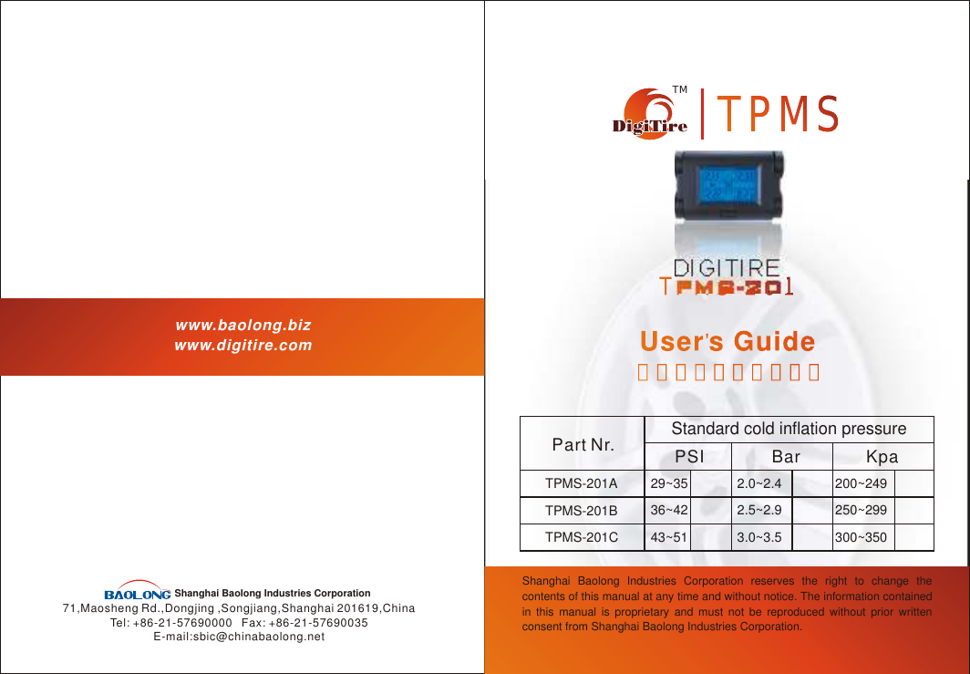
Baolong TPMS201 Tire Pressure Monitoring System User Manual

Shanghai Baolong Industries Corporation Tire Pressure Monitoring System Users Manual

Users Manual

TPMS-201TPMS-201TMTPMSTPMSDIGITIREwww.baolong.bizwww.digitire.com71,Maosheng Rd.,Dongjing ,Songjiang,Shanghai 201619,ChinaTel: +86-21-57690000   Fax: +86-21-57690035E-mail:sbic@chinabaolong.netShanghai Baolong Industries Corporation Shanghai Baolong Industries Corporation reserves the right to change the contents of this manual at any time and without notice. The information contained in this manual is proprietary and must not be reproduced without prior written consent from Shanghai Baolong Industries Corporation.User s GuideUser  s Guide用户手册(简体中文)用户手册(简体中文)Part Nr.Standard cold inflation pressurePSI Bar KpaTPMS-201ATPMS-201BTPMS-201C29~3536~4243~512.0~2.42.5~2.93.0~3.5200~249250~299300~350
Dear customers,Please use the serial number shown below to register on our website www.digitire.com. This will help you to use the following services:1. Timely after-sale service;2. Promotional information on all our products;3. Communication among the Digitire TPMS users.This product requires a trained technician to install or remove. Ensure that you follow the User's Guide closely. Any incorrect installation or removal may damage the product.Whenever you hear “Beep-Beep” or “Beep-Beep-Beep” beeping sound, or see an       or an       on the display, you must pull the vehicle over to a safe area where you can check and correct the problem.
1  Brief introduction 2  How the system works3  Installation manual (For professional user only)    3.1  Installation of sensor    3.2  Installation of antenna    3.3  Installation of receiver     3.4  Installation of display     3.5  How to remove the sensor 4  Key functions and operation guidelines     4.1  Key functions    4.2  Data display     4.3  Warning signals    4.4  Resetting the system     4.5  ID Module checkout    4.6  Changing wheel positions     4.7  Replacing a sensor5  Trouble shooting 6  Specifications of the product7  The authentication announcement for Europe and     North America, and the corporation's declarations    7.1  FCC's authentication announcements    7.2  European regulations announcements     7.3  Product Application and warnings8  Others 9  WarrantyCONTENT 1  Brief Introduction  Thank you very much for choosing Digitire TPMS. As a reliable vehicle proactive safety device, it provides real-time monitoring of all the tires, including air pressure and temperature. It will give warnings about abnormal conditions such as slow leakage, rapid leakage, low pressure, high pressure and high temperature. In addition, Digitire TPMS can identify its corresponding components easily after wheel change or sensor change.The whole package consists of the components as follows:                                                                  A displayFour sensors  Two antennas A receiverUser's guide Strips A stickerTwo double-sided sticky tapes11231018192023243791011121414161720212278
Display detailed key :   Front surface     Reverse side 2  How the system worksA sensor is installed with the valve stem in each wheel, monitoring the pressure and temperature conditions inside each wheel of the vehicle, and wirelessly sends the data it collects to the receiver through two antennas. The receiver then transfers the data by wire to the display, which is installed on the dashboard and digitally displays the pressure and temperature. The system continuously analyzes the data to detect any abnormal conditions. It will trigger different alarm settings to report various abnormal conditions.3 Installation Manual (For professional technicians only, end users can skip this section and go directly to #4, Key Functions and Operation Guidelines)3.1 Installation of sensorBefore installation, make sure you identify each sensor (A, B, C and D) respectively. Each sensor has its own electronic module and nut. For example, you can easily distinguish the “C” electronic module because the letter “C” is at the very end of the S/N. (e.g.  T5200-SM5300-050816-015B-C). Each nut also has an engraved letter that show which sensor it belongs to.Key buttonID moduleRESET Key ⑦Valve cap①Self-lock screw ②Electronic module③Valve  stem ④Plastic washer⑥Nut ⑤metal washerSensorAntennaReceiverDispiayAntennaSensorSensor Sensor32Holding keyT5200-SM5300-050816-015B-CC
Each sensor has a corresponding ID module. With four ID modules mounted on two sides, the display resembles a vehicle with four wheels. The ID modules should be placed in the same positions on the display as the corresponding sensors are installed on the vehicle. For instance, if the “C” sensor is installed in the left rear wheel position, then the corresponding “C” ID module has to be placed in the “left rear wheel” position on the display. The manufacturer has set as the default that A, B, C and D ID modules are placed respectively on the Left Front Wheel (LFW), Right Front Wheel (RFW), Left Rear Wheel (LRW) and Right Rear Wheel (RRW).ACBD3.1.1 Use a self-locking screw ①to join electronic module ②and valve stem ③ together. The assembly is adjustable to fit the various angles of the rims.3.1.4 Lock the rim on the tire changer. (If the mounting head of the tire changer is positioned at 12 o'clock, then the valve should be at the 7 o'clock position.) Apply lubricant on both tire bead and rim. Mount the lower tire bead on the rim. Ensure that the tire bead does not touch the electronic module during mounting.712A3.1.3 Place plastic washer ④,metal washer ⑤and nut ⑥on the valve stem, and tighten with 3.5~4.5Nm (30~40inch pounds) torque.3.1.2 Insert the valve stem through the rim hole from inside. Adjust the angle between the valve stem and the electronic module to fit the rim properly, and then screw tight the valve stem.54CBD
3.1.5 Mount the upper tire bead the same way. (If the mounting head of the tire changer is positioned at 12 o'clock, then the valve should be at the 5 o'clock position.) Inflate the tire to nominal pressure.5123.1.6 Apply soapsuds on the valve tip. If no leakage is found, put on the valve cap ⑦.Otherwise determine the reason for the leakage and reinstall this sensor.3.3 Installation of receiver 3.3.1 Tighten the connecting nut of the antenna cable to the receiver only finger tight. Do not twist the cable.Connecting nut3.1.7 Dynamic balance the wheel before it is put back on the vehicle. Use the same procedures to install the other three sensors. Please install A, B, C, and D sensors on the Left Front Wheel (LFW), Right Front Wheel (RFW), Left Rear Wheel (LRW) and Right Rear Wheel (RRW) respectively.3.2  Installation of antenna3.2.2 Place the cable of the antenna along the front edge of the dashboard.3.2.1 Installing the antennaPlace the two antennas underneath the rubber layers of the two 'A' posts along the fringe of the Dashboard.763.3.2 Remove the cover on the side of the dashboard or below the dashboard. Align all receiver cables. Fasten the receiver on the metal frame inside the dashboard with a strap or double-sided tape.Recciver
3.3.3 Now, if correctly connecting the  red wire and the blue wire from the receiver with the positive power cable out of battery and the negative ground in the circuit board of the car respectively, the screen background will be lighted up in blue and displaying “000”at the four corners in the display.  Then, the joint connecting wires should be safely wrapped with friction tape.3.5  How to remove the sensor       (When removing or replacing a sensor and taking off        or changing the tire from the rim of the wheel)3.4  Installation of displayFix the display unit on the dashboard with double-sided tape. Do not block the driver's view. Pay attention to the viewing angle of the display.3.5.2 Firmly fix the wheel on the turntable clamps. (If the mounting head of the tire changer is positioned at 12 o'clock, then the valve stem should be at the 11 o'clock position.) Apply lubricant to both tire bead and rim, and then dismount the upper tire bead.11 12+-3.5.1 Deflate the tire and remove the wheel weights from the rim. Push the tire bead away from the rim. Make sure to always set the bead breaker at least 90 degrees from the valve stem to avoid damaging the electronic module.>90983.3.4 Tie up all the cables with a strap and put in the compartment. Then replace the dashboard cover.3.5.3 Use the same procedure to dismount the lower tire bead. (If the mounting head of the tire changer is at the 12 o'clock position, then the valve should also be at the 12 o'clock position.)12
3.5.4 Final inspection: Visually inspect the rim, valve stem and electronic module to ensure no damage has occurred.4 Key Functions and operation guidelines 4.1 Key functions4.1.1 The sensors continuously monitor the air pressure and temperature of the tires. 4.1.2 When tire pressures and temperatures are all at normal settings, the sensor will transmit data to the receiver at eight-minute intervals. Every time the display receives the latest data, it will refresh and display the tire pressures and temperatures of all four tires.4.1.3 If the sensor detects any abnormal condition, it will immediately send the signals to the display. The display will instantly give an alarm and indicate the problem.The little screen is displaying as follows:Leakage iconLFW pressure (or Temperature)     RFW pressure(or Temperature)Pressure unit                                  Temperature unit              LRW pressure (or Temperature) RRW pressure (or Temperature)Abnormality icon11104.2 Data display To read the tire pressure and temperature of each tire, simply press the key button on the display. Press again to switch between air pressure and temperature.When pressing the key button, the background will light up for 9 seconds before it turns off.Temperature modePressure mode
13124.3.1. HearWhen you hear the warning sound “Beep-Beep” or “Beep-Beep-Beep”, pull over to a safe area to check the problem. 4.3.2. CheckWhen you hear the warning sound, please check the warning icons on the display. The background will light up automatically.a. If you see an         , that means one of the tires has a high temperature or an abnormal pressure (high or low)b. If you see an       , that means one of the tires is leaking rapidly.c. If no icon appears, that means one of the tires is leaking slowly.4.3.3. LocateEach number on the display has a square frame. If the frame has disappeared, this tire is the problem tire.The warning signals are shown as below:Low Pressure warningPressure is lower than 1.6Bar(23PSI)--------TPMS-201A1.9Bar(28PSI)--------TPMS-201B2.3Bar(33PSI)--------TPMS-201C   High Pressure warningPressure is higher than 3.2Bar(46PSI)----TPMS-201A3.8Bar(55PSI)----TPMS-201B4.3Bar(62PSI)----TPMS-201CHigh Temperature warningThe temperature inside the tire is higher than  80 C(176 F)Abnormality warning4.3 Warning SignalsRapid Leakage warningSlow Leakage warningChanges of pressure is greater than 0.08 Bar/15 secondsChanges of pressure is greater than 0.15 Bar within 10 days
4.4 Resetting the systemThe system has to be reset to re-identify the ID module in the following situations.1) Replace the ID module;2) Interchange the positions of the ID modules and sensors;Or, if the display continues to show some incomprehensible codes or “---”, or the data does not refresh, you may press the reset button on the back of the display to restart.If the 6-digit ID number shown on the display matches the corresponding 6-digit ID number on the ID module, the system is working Properly. Otherwise it isn't. In this case, pull out the ID module and put it back properly. If the problem still exists, the sensor and its ID module need to be replaced.Press and hold the button again for 3 seconds and the system will resume normal working condition.RE-SET Key15144.5  ID Module checkoutIf you see one or more “---” on display, ID module may not be properly plugged into the display. Press and hold the button on the display for 3 seconds and the system will begin the checkout process. Each ID module has a 6-digit ID code. The display will show the first 3 digits. Press again and it will show the last 3 digits. Important:  When plugging the ID module into the display, make sure the “needle plugs” on the ID module line up with the slot form on the side of the display. Otherwise the ID module could be damaged when plugged in by force.Holding keyBefore pulling out the ID module, firmly push the holding key on the back of the display. Otherwise the ID module may be damaged.
4.6  Changing wheel positionEach sensor and its corresponding ID module have the same ID code. With four ID modules mounted on two sides, the display resembles a vehicle with four wheels. The ID modules should be placed in the same positions on the display as the corresponding sensors are installed on the vehicle. Therefore when you change a wheel position, the ID module position should also be changed.For example, if you interchanged the LFW (Left Front Wheel) and the LRW (Left Rear Wheel), you should also interchange the positions of the upper left ID module and the lower left ID module.4.7  Replace sensorWhen you replace a sensor, first install the new sensor in the wheel. Then plug the ID module came with the sensor in the corresponding position of the display. For example, if you replaced a sensor in the RRW (Right Rear Wheel), then you should plug the new ID module in the lower right position of the display.1716
5 Trouble shootingProblem                Probable reason                   Solution “- - -”shows on the display1. ID module is not properly connected with the displayID Module checkout. See 4.5. 2. System failure Press RESET key  to restart the system3. Receiver did not receive the signal from the sensorContact your distributor1.Data does not refresh;2.Back light does not turn off;3.The display continues to show incomprehensible codes.System failure  Press RESET key to restart the system Nothing shown on the displayDisplay power cord is not properly plugged in Contact your distributor 6 Parameters of the productSensor Weight :36 g ( 1.26 oz. ) Dimensions :  1.5 X 2.8 X 6.4 cm ( 0.59 x 2.50 x 1.11 inch ) Operating Temp. Range :  -40 C to 125 C                                            (-40 F to 257 F)Pressure Accuracy:    0.05 Bar (0.73 PSI)Temperature Accuracy :    2 C (3.6 F)Battery life :  5 years  (Theoretically estimation: 10 years ) Maximum range :  5.4 Bar (78 PSI) Frequency :  433.92MHzReceiverPower Consumption: Max :  220mWPower Supply :  DC12 VoltWeight :  48 g (1.7 oz.) Dimensions :  2.3 X 3.7 X 8.8 cm ( 0.91 x 3.47 x 1.46 inch ) Operating Temp. Range :  -40 C to 85 C (-40 F to 185 F)Display Power Consumption ;Regular :  130 mW Max :  230mWPower Supply :  DC12 VoltWeight :  75 g ( 2.65 oz. ) Dimensions :  2.2 X 4.9 X 7.7 cm ( 0.87 x 3.03 x 1.93 inch ) Operating Temp. Range :  -20 C to 70 C (-4 F to 158 F) Pressure resolution : 0.01Bar (0.2PSI)Temperature resolution :  1 C(2 F) 1918
7  The authentication announcement for     Europe and North America, and the     corporation's declarations. 7.1 FCC's authentication announcement This device complies with Part 15 of the FCC Rules. Operation is subject to the following two conditions: (1) this device may not cause harmful interference, and (2) this device must accept any interference received, including interference that may cause undesired operation. This equipment has been tested and found to comply with the limits for a Class B digital device, pursuant to Part 15 of the FCC Rules. These limits are designed to provide reasonable protection against harmful interference in a residential installation. This equipment generates uses and can radiate radio frequency energy and, if not installed and used in accordance with the instructions, may cause harmful interference to radio communications. However, there is no guarantee that interference will not occur in a particular installation. If this equipment does cause harmful interference to radio or television reception, which can be determined by turning the equipment off and on, the user is encouraged to try to consult the dealer for help. Changes or modifications to this device without the express approval of Shanghai Baolong Industries Corporation may void the user's authority to use this device. 7.2 European regulations announcementsThis device complies with all European Electromagnetic compatibility regulations (95/54/EC and EN300 220-1). The equipment has been tested and found to comply with the above regulations, and in addition it meets the requirements for low powered transmitters/receivers as defined by the relevant radio approval authority. The regulations are designed to provide reasonable protection against harmful interference or susceptibility. Changes made to this device without the express approval of Shanghai Baolong Industries Corporation. may void the user's authority to use this device. 2120
7.3  Product Application and Warnings7.3.1 Product FunctionThis is a monitoring device. It provides real-time monitoring on each tire for pressure and temperature, and gives warning to any abnormal condition. The driver should react promptly to the warning and correct the problem.7.3.2 Important Notice about Installation  This product should only be installed by a trained technician according to the manufacturer's instructions. All instructions are in the user's manual and/or CD. 7.3.3 ApplicationWe recommend to use in cars or light trucks with 4 tubeless tires. We have 3 types of TPMS for different vehicles with different cold inflation pressure. Please refer to the application chart as follows:If you need the TPMS beyond above pressure ranges, we can custom it according to your requirement. 7.3.4 Warning When you observe any warning, immediately reduce speed and pull the vehicle to a safe place, where you can inspect and repair the tire.              23228 Others8.1 When you park the vehicle, the tire temperature will decrease and thus the tire pressure will also decrease. If the system gives rapid leakage warning within half an hour after parking the vehicle, this might be the reason and should be considered as normal.8.2 If the display unit does not receive signals properly from a sensor, the system will detect it within an hour and show “---” on the corresponding location in the display.8. 3 Sometimes you may see “---” when the vehicle is parked. This might be caused by the surrounding interference. This is normal. The display will show correct data when you start the vehicle.8.4  Try to avoid parking the vehicle under strong sunlight. The LCD screen may be damaged after one hour of exposure to 70°C (158°F) in-car temperature.Part Nr.Standard cold inflation pressurePSI Bar KpaTPMS-201ATPMS-201BTPMS-201C29~3536~4243~512.0~2.42.5~2.93.0~3.5200~249250~299300~350
9 WarrantyThis Warranty covers substantial manufacture's defects in workmanship and materials. It does not cover any unit that is damaged beyond normal usage,  not properly installed, subject to chemical contact, or other acts not sanctioned by the Owner's Manual.All components are covered for one(1) year and unlimited mileage following the date of purchase.The Digitire Warranty will be honored by any authorized Digitire Dealer. The owner is required to provide dated proof of the purchase. The authorized dealer will determine if there is warrantable condition associated with materials and/or manufacturing workmanship. If a warrantable condition exists, the component will be replaced free of charge and shipping prepaid. The owner is responsible for any labor and installation charges.The warranty does not include any further obligation whatsoever, including but not limited to actual installation of the replacement unit on the customer’s vehicle.2524All other Warranties, explicit or implied, are disclaimed. All collateral agreements, which purport to modify this limited Warranty are of no effect. The absolute limit of liability is the purchase price of the unit. Digitire System inc. is not liable for any direct, consequential, indirect or punitive damages of any kind.Type: TPMS-201; Voltage: DC 3.6V; Frequency: 433.92MHz;Temperature: -40℃ to 125℃; Transmitting BlockThis block is made up of Li-cell, Senor, CPU and Radio circuit. Through the supply of the Li-cell, the sensor accurately monitors the data. The CPU will operate the data and transmit the Radio, which including the pressure data, the temperature data and ID.                  Receiving BlockThis block is made up of power supply, radio receiving, CPU and display.Power supply is in charge of the supply to the whole block, the management of the radio receiving from the transmitter and transmission to the CPU. CPU operates the data, and then transmits them to the display. CPU will trigger the warning system in case abnormality happens.

Navigation menu