Barrett Communication 4050HF 4050 HF Transceiver User Manual
Barrett Communication Pty. Ltd. 4050 HF Transceiver
user manual
BCM40500/30
© Barrett Communications
+HDG2IÀFH
Barrett Communications Pty Ltd
47 Discovery Drive, Bibra Lake, WA 6163 Australia
Tel: +61 8 9434 1700 Fax: +61 8 9418 6757
Email: information@barrettcommunications.com.au
www.barrettcommunications.com.au
Operating and Installation
Manual
Barrett 4050 HF SDR Transceiver

BARRETT 4050 HF SDR TRANSCEIVER - OPERATING AND INSTALLATION MANUAL
2
Contents
Introduction ............................................................................................................ 12
Terms & Abbreviations ....................................................................................................13
Exploring the 4050 HF Transceiver .........................................................................15
Transceiver Front Panel ...................................................................................................15
Keypad .............................................................................................................16
Transceiver Front Panel Rear View ..................................................................................16
Transceiver Rear Panel ....................................................................................................17
Switching the Transceiver On / Off .................................................................................18
Switching the Transceiver On ...........................................................................18
Switching the Transceiver Off ...........................................................................19
Volume .............................................................................................................................19
Power Button Menus .......................................................................................................20
Capture ............................................................................................................20
Reboot / Shutdown ..........................................................................................21
Resync ..............................................................................................................21
Locking and Unlocking the Screen ..................................................................................21
Display .............................................................................................................................22
Using the Microphone .....................................................................................................24
Programming Functions .........................................................................................25
Program a New Channel from the Front Panel ...............................................................25
Emergency Calls ......................................................................................................26
Receiving an Emergency Call ..........................................................................................27
Barrett Selective Calling System ............................................................................28
Summary of Calling Systems ...........................................................................................28
Selective Call - Selcall........................................................................................29
Selcall Self IDs .............................................................................................29
Selcall Decode .............................................................................................29
Selcall Transmit ...........................................................................................29
Selective Call - Telcall ........................................................................................29
Special Notes for the OEM Selective Call Protocol ............................................30

BARRETT 4050 HF SDR TRANSCEIVER - OPERATING AND INSTALLATION MANUAL
3
Station ID Ranges ............................................................................................................30
Call Key ............................................................................................................................31
Call Type ...........................................................................................................31
Beacon Call .................................................................................................32
Send a Beacon Call ................................................................................32
Receive a Beacon Call ............................................................................32
Selcall .........................................................................................................33
Send a Selcall ........................................................................................33
Receiving a Selcall Directed to Your Transceiver .....................................33
Receiving Allcalls, Group Calls and Sub-group Calls ..............................34
Receiving an Allcall, Group Call or Sub-group Call .................................35
Telcall ..........................................................................................................35
Send a Telcall .........................................................................................35
Last Number Redial ...............................................................................37
Receive a Telcall .....................................................................................37
Pagecall ......................................................................................................38
Send a Pagecall .....................................................................................38
Receive a Pagecall ..................................................................................39
GPS Req ......................................................................................................40
GPS Pos .......................................................................................................41
Hangup ......................................................................................................42
Status .........................................................................................................43
Requesting Another Station’s Status .....................................................43
Secure .........................................................................................................44
Contacts ...........................................................................................................45
Favourites .........................................................................................................46
Call History .......................................................................................................47
All ...............................................................................................................47
Received .....................................................................................................47
Sent ............................................................................................................48
Menus ......................................................................................................................49
Settings ............................................................................................................................49
Menu Map ........................................................................................................................50
General.............................................................................................................52
Transceiver Name ........................................................................................52
Mic Up / Down Keys ....................................................................................53

BARRETT 4050 HF SDR TRANSCEIVER - OPERATING AND INSTALLATION MANUAL
4
Date and Time ............................................................................................53
Time Zone .............................................................................................54
BITE Test ......................................................................................................54
Language ....................................................................................................54
Security ............................................................................................................55
Hopping PIN ...............................................................................................55
Frequency Hop Rate ....................................................................................56
OEM Secure Type ........................................................................................56
OEM Secure Key ..........................................................................................56
Secure Digital Voice Key ..............................................................................57
Secure Data Key ..........................................................................................57
Secure Calls Hop Rate .................................................................................58
Secure Call Code .........................................................................................58
TC2 Programming Mode .............................................................................58
Labels ...............................................................................................................59
Add a Channel Label ...................................................................................59
Edit a Channel Label ...................................................................................60
Delete a Channel Label ...............................................................................60
Channels ..........................................................................................................60
Search For a Channel ..................................................................................61
Add a Channel ............................................................................................61
Number .................................................................................................62
Label .....................................................................................................62
Rx Frequency .........................................................................................62
Tx Frequency .........................................................................................63
Mode ....................................................................................................63
Tx Power ................................................................................................63
Selcall Format ........................................................................................64
ALE Channel ..........................................................................................64
Antenna Socket .....................................................................................64
Save Channel ..............................................................................................65
Edit a Channel ............................................................................................65
Delete a Channel .........................................................................................66
Contacts ...........................................................................................................66
Sort Contacts ..............................................................................................66
Search Contacts ..........................................................................................67
Add a Contact .............................................................................................67
First Name .............................................................................................68
Surname ................................................................................................68

BARRETT 4050 HF SDR TRANSCEIVER - OPERATING AND INSTALLATION MANUAL
5
ID Type ..................................................................................................68
Four Digit .........................................................................................69
Six Digit ...........................................................................................69
ARINC ..............................................................................................69
ALE 2G Alias ..........................................................................................70
ALE 3G Alias ..........................................................................................70
Email Address ........................................................................................70
Phone Number ......................................................................................71
Favourite ...............................................................................................71
Edit Contact ................................................................................................71
Delete Contact ............................................................................................72
Scan .................................................................................................................72
Scan Rate ....................................................................................................72
Dwell Time ..................................................................................................73
Resume Time ..............................................................................................73
Table Selection ............................................................................................73
Edit Scan Tables ..........................................................................................74
Add a Scan Table ...................................................................................74
Scan Table Name ..............................................................................75
Antenna Socket ...............................................................................75
Scan Table Channel List ....................................................................75
Save a Scan Table ..................................................................................76
Edit a Scan Table ...................................................................................76
Delete a Scan Table ................................................................................76
Mute ................................................................................................................77
Syllabic Sensitivity .......................................................................................77
Signal Strength Level ..................................................................................77
Selcall ...............................................................................................................78
Audio in Tx .................................................................................................78
Preamable Time ..........................................................................................79
Default Int Selcall ID (4 Digits) ....................................................................79
Default Int Selcall ID (6 Digits) ....................................................................79
OEM Privacy Key .........................................................................................80
OEM Selcall ID (4 Digits) .............................................................................80
OEM Selcall ID (6 Digits) .............................................................................80
Selcall Networks..........................................................................................81
Add a Selcall Network ...........................................................................81
Selcall Network Alias ........................................................................82
Selcall Format ..................................................................................82

BARRETT 4050 HF SDR TRANSCEIVER - OPERATING AND INSTALLATION MANUAL
6
4 Digit Selcall ID ...............................................................................82
6 Digit Selcall ID ...............................................................................83
Save a Selcall Network ...........................................................................83
Edit a Selcall Network ............................................................................83
Delete a Selcall Network ........................................................................84
GPS Broadcast Enable .................................................................................84
Transceiver Lock ..........................................................................................85
Audio ...............................................................................................................86
Beep Level ...................................................................................................87
Alarm Audio Level .......................................................................................87
Ring Tones ..................................................................................................88
5[&RQÀJXUDWLRQ .........................................................................................88
7[&RQÀJXUDWLRQ .........................................................................................89
Audio Bandwidth ........................................................................................89
Line Audio ..................................................................................................90
Line Follows Digital Voice ...........................................................................90
Line Out Level .............................................................................................91
Line In Level ................................................................................................91
Audio Record ..............................................................................................91
RF .....................................................................................................................92
Rx Preamp ...................................................................................................92
Tx Over Beep ...............................................................................................93
Transmit Timeout ........................................................................................93
Noise Blanker ..............................................................................................94
Tx Power Level ............................................................................................94
AGC Hang ...................................................................................................95
Broadcast Filter ...........................................................................................95
Preselector ..................................................................................................95
IO .....................................................................................................................96
RS232 Out ..................................................................................................96
RS232 Baud Rate ........................................................................................97
EXT Alarm Type ...........................................................................................97
Antenna 1 Type ...........................................................................................98
Antenna 2 Type ...........................................................................................99
ALE .................................................................................................................100
ALE Set-up Overview .................................................................................100
Combined ALE / Selective Call - Overview .................................................101
ALE State Settings for 2G ..........................................................................101
ALE State .............................................................................................102

BARRETT 4050 HF SDR TRANSCEIVER - OPERATING AND INSTALLATION MANUAL
7
Preset Map ..........................................................................................102
Response Control ................................................................................103
Sounding Control ................................................................................103
Sounding Address ...............................................................................104
LQA Exchange .....................................................................................104
LQA Averaging ....................................................................................105
LQA Decay Rate ...................................................................................105
Threshold Test .....................................................................................106
SINAD Threshold .................................................................................106
BER Threshold .....................................................................................107
ALE State Settings for 3G ..........................................................................107
Voice Link Timeout ..............................................................................108
Data Link Timeout ...............................................................................108
LQA Averaging ....................................................................................108
LSU Mode ............................................................................................109
ALE 3G Channels .................................................................................110
ALE 3G Addresses ................................................................................110
Save the ALE Settings ...............................................................................110
System Info ....................................................................................................111
System Status ...........................................................................................111
Version Information ..................................................................................112
Transceiver Options ...................................................................................113
Enter Option PINs ................................................................................113
4050 Serial Number ..................................................................................114
Call History .....................................................................................................114
Export ............................................................................................................114
Display ...........................................................................................................115
Level of Display Backlight ..........................................................................116
Backlight Timeout .....................................................................................116
Display Timeout Behaviour........................................................................116
Transmit Meter Mode ...............................................................................117
Receive Meter Mode .................................................................................117
Temperature Units ....................................................................................117
Network .........................................................................................................118
WiFi Operation Mode................................................................................118
WiFi Client ...........................................................................................118
WiFi Access Point Mode .......................................................................120
WiFI Access Point Setup .................................................................120
WPS Push Button ...........................................................................122

BARRETT 4050 HF SDR TRANSCEIVER - OPERATING AND INSTALLATION MANUAL
8
BoB.................................................................................................................123
BoB Name .................................................................................................123
Network Settings ......................................................................................124
DHCP ...................................................................................................124
IP Address ...........................................................................................125
Network Mask .....................................................................................125
Default Gateway .................................................................................125
Primary DNS ........................................................................................126
Secondary DNS ....................................................................................126
Network Status .........................................................................................127
Import / Update .............................................................................................127
,PSRUW&RQÀJXUDWLRQ ................................................................................128
Program Firmware ....................................................................................129
Channels ...................................................................................................................... ...130
Selecting a Channel ........................................................................................131
Search For a Channel ......................................................................................131
Hop .................................................................................................................................132
Selecting the Hop Band ..................................................................................132
Entering the Security Code .......................................................................132
Security Codes and Bandwidths ..........................................................132
To Enable Hopping Mode ...............................................................................133
To Disable Hopping Mode ..............................................................................133
Tune ................................................................................................................................134
Mode ..............................................................................................................................134
NR ...................................................................................................................................135
Scan ................................................................................................................................135
Selcall Scan .....................................................................................................136
Signal Strength Scan (SSL Scan) .....................................................................136
Voice (Syllabic) Scan .......................................................................................136
Mute ...............................................................................................................................137
Swipe Menu ...................................................................................................................138
Wireless Application .............................................................................................139
Downloading the Barrett SDR Remote Control Head Setup App .................................139
For Windows PCs ............................................................................................139
For iOS and Android Devices ..........................................................................140

BARRETT 4050 HF SDR TRANSCEIVER - OPERATING AND INSTALLATION MANUAL
9
Installing the Barrett SDR Remote Control Head Setup App .......................................140
For Windows PCs ............................................................................................140
For iOS and Android Devices ..........................................................................141
Connecting the Wireless Device to the SDR .................................................................144
Preparing the SDR ..........................................................................................144
Invoking the App ............................................................................................145
Exploring the App ..........................................................................................................146
Disconnecting the Wireless Device from the SDR ........................................................146
Cooling Fan ...........................................................................................................147
Installing the Cooling Fan .............................................................................................147
Connectors ............................................................................................................ 148
Power Connector ...........................................................................................................148
GPS Connector ...............................................................................................................148
Aux Control Head / BoB Connector ................................................................................149
Auxiliary Connector .......................................................................................................149
ATU Connector ...............................................................................................................151
Microphone Connector ..................................................................................................151
Control Head Rear Panel Connector ..............................................................................152
Cooling Fan Connector ..................................................................................................152
6SHFLÀFDWLRQV ........................................................................................................153
General ....................................................................................................................... ....153
Receiver ..........................................................................................................................154
Transmitter ................................................................................................................... ..155
Installation ............................................................................................................156
Mobile Pack ...................................................................................................................156
Land Based Systems ......................................................................................................159
Fixed Station Installations ..............................................................................160
Site Selection Recommendations .............................................................160
Power Supply ...........................................................................................161
Voltage Drop ...........................................................................................161
Protection Fuse ........................................................................................161
Antenna ...................................................................................................162

BARRETT 4050 HF SDR TRANSCEIVER - OPERATING AND INSTALLATION MANUAL
10
912 Single Wire Broadband Dipoles ....................................................162
912 Multi wire Broadband Dipoles ......................................................165
913 Series Helical Dipoles ....................................................................167
915 Wire Dipole ..................................................................................169
4017 Automatic Tuning Horizontal Dipole Antenna ..................................171
Connection Details for a 4050 Transceiver and 4017 Automatic Tun-
ing Horizontal Dipole Antenna ............................................................172
911 Automatic Antenna Tuner for Base Station Installations ...................173
Antenna ..............................................................................................173
Transceiver and Tuner Mounting .........................................................173
Ground (Earth) System ........................................................................174
Electrical Checkout ..............................................................................175
Connection Details for a 4050 Transceiver and 911 Automatic
$QWHQQD7XQHULQD%DVH6WDWLRQ&RQÀJXUDWLRQ ...................................176
4011 Automatic Antenna Tuner for Base Station Installations ..................177
Connection Details for a 4050 Transceiver and 4011 Automatic
$QWHQQD7XQHULQD%DVH6WDWLRQ&RQÀJXUDWLRQ ...................................178
Mobile Installations ........................................................................................180
Site Selection Recommendations ..............................................................180
Power Wiring ...........................................................................................181
Earthing ....................................................................................................181
Antenna ....................................................................................................182
Antenna Mounting ..................................................................................182
Antenna Feed Cables ...............................................................................182
Voltage Standing Wave Ratio (VSWR) ......................................................182
Noise Suppression ....................................................................................182
Interference Suppression Kit ...............................................................183
General Noise Suppression Tips ...........................................................185
2019 Automatic Tuning Mobile HF Antenna .............................................186
Mounting the Barrett 2019 Automatic Tuning Mobile HF Antenna .....186
Antenna Assembly ...............................................................................189
Mounting the Base Spring .............................................................189
Mounting the Whip Sections .........................................................189
Connection Details for a 4050 Transceiver with Mobile Pack and 2019
Automatic Tuning Mobile HF Antenna .................................................191
Testing the Barrett 2019 Automatic Tuning Mobile HF Antenna ..........192
914 Series Manual Tap Whip Antenna ......................................................193
Installation ..........................................................................................193
Operation Instructions.........................................................................195

BARRETT 4050 HF SDR TRANSCEIVER - OPERATING AND INSTALLATION MANUAL
11
Connection Details for a 4050 Transceiver with Mobile Pack and 914
Manual Tapped Mobile Antenna ........................................................196
2018 Mobile Magnetic Loop Antenna ......................................................197
Connection Details for a 4050 Transceiver with Mobile Pack and a
2018 Mobile Magnetic Loop Antenna .................................................197
Marine Installations .......................................................................................................198
Antenna Selection .........................................................................................198
Antenna ........................................................................................................199
Transceiver and Tuner Mounting ...................................................................199
Ground (Earth) System ..................................................................................199
Corrosion ......................................................................................................200
Electrical Checkout .........................................................................................200
Connection Details For a 4050 Transceiver and 911 Automatic Antenna
Tuner in a Marine Installation .........................................................................201
Overview of HF Operation ....................................................................................203
HF Propagation ..............................................................................................................203
Radio Wave Propagation ...............................................................................................204
Factors Which Affect HF / SSB Communications ...........................................................205
Frequency Selection ........................................................................................205
Time of Day ....................................................................................................205
Weather Conditions .......................................................................................205
Man-made Electrical Interference ...................................................................206
6\VWHP&RQÀJXUDWLRQDQG,QVWDOODWLRQ ...........................................................206
HF Communications Compared with VHF or UHF Short Distance Communications ....206
Compliance ...........................................................................................................207
FCC RF Exposure Compliance Statement ......................................................................207
RF Exposure Warning .....................................................................................................208
FCC Modulation Modes .................................................................................................208
Industry Canada Modulation Modes ............................................................................208
Limited 3 Year Warranty Statement .....................................................................209
Warranty Registration and Technical Support .....................................................210
Warranty Registration Contact Details .........................................................................211
Index .....................................................................................................................212

12
BARRETT 4050 HF SDR TRANSCEIVER - OPERATING AND INSTALLATION MANUAL
Introduction
The Barrett 4050 Transceiver is an SDR based HF SSB Transceiver with a fre-
quency range of 1.6 to 30 MHz. The Barrett 4050 is designed using the latest
technology enabling a physically small package with a full feature complement.
Designed to operate in the most arduous environments, as encountered in off-
road vehicles, vessels and aircraft, the Barrett 4050 will provide many years of
HIÀFLHQWDQGWURXEOHIUHHVHUYLFH
The Barrett 4050 supports features such as Selective Call (Selcall), direct dial
WHOHSKRQHFRQQHFWLRQWREDVHVWDWLRQVÀWWHGZLWKWHOHSKRQHLQWHUFRQQHFW
systems (Telcall), GPS location, ALE (Automatic Link Establishment), frequency
hopping, data transmission and remote diagnostics. These features make the
Barrett 4050 HF Transceiver one of the most economical and versatile HF Trans-
ceiver available today.
The Barrett 4050 Transceiver caters for increased use of HF data transmission
for Internet email access and point-to-point data applications, by providing
a comprehensive data modem interface port, high speed transmit-to-receive
VZLWFKLQJDKLJKVWDELOLW\IUHTXHQF\VWDQGDUGDQGDQHIÀFLHQWFRROLQJV\VWHP
option.
The Barrett 4050 Transceiver can be operated in either a local (desktop) con-
ÀJXUDWLRQIRUEDVHVWDWLRQDSSOLFDWLRQVRUZLWKWKHDGGLWLRQRIDQLQH[SHQ-
VLYHPRELOHSDFNLQDUHPRWHFRQWUROWUXQNPRXQWFRQÀJXUDWLRQIRUPRELOH
applications.
The Barrett 4050 Transceiver can be controlled from all major mobile and
desktop platforms. The Barrett 4050 handset app supports iOS, Android and
Windows devices for wireless voice and radio control. Full remote control is
available via the Barrett 4050 Virtual Control Head app, providing unprece-
dented access to all transceiver functionality on Windows and OSX computers,
iPad and Android tablets.
Operated from either 12 volt (13.8 V) DC or 24 V DC supplies, the transmitter is
rated at 125 or 150 watt PEP respectively in voice mode and is protected from
over-voltage or reverse-voltage application.
8SWRFKDQQHOVGHSHQGLQJRQWKHYDULDQWDUHDYDLODEOHWREHÀHOG
or workshop programmable. Auxiliary features such as Selcall, Telcall, scanning,
mute status, alarm system etc. can be individually enabled or disabled for every
channel as required to suit your operation.
Teamed with other matching Barrett products which include antennas, power
supplies, vehicle tracking packages and HF modems, the Barrett 4050 HF Trans-
ceiver becomes a powerful tool, providing solutions to many long distance
communication requirements.

13
BARRETT 4050 HF SDR TRANSCEIVER - OPERATING AND INSTALLATION MANUAL
Please note that this manual describes all the features of the 4050 HF SDR
Transceiver and that some variants of the 4050 may not have all the features
installed.
Terms & Abbreviations
Term / Abbrevi-
ation 'HÀQLWLRQ
ALE Automatic Link Establishment
AM Amplitude Modulation
ARINC A set of standards as established by Aeronautical Radio,
Incorporated (ARINC).
Call History A list containing details of the last thirty calls received.
CCIR 2QHRIPDQ\SRVVLEOH6HOFDOOIRUPDWVDVGHÀQHGE\WKH
Consultative Committee on International Radio (CCIR).
CW Continuous Wave (used for Morse code)
dB Decibels
dBm Power ratio in decibels (dB) of the measured power refer-
enced to one milliwatt (mW).
DSP Digital Signal Processing
ESU Encryption Synchronisation Unit
FHSS Frequency Hopping Spread Spectrum
FSK Frequency Shift Keying
GPS Global Positioning System
HF High Frequency
,GHQWLÀFDWLRQ
Code
7KHXQLTXHUHIHUHQFHLGHQWLÀFDWLRQ,'
of a Transceiver (not serial number).
IF Intermediate Frequency
LCD Liquid Crystal Display
LSB Lower Sideband
LUF Lowest Usable Frequency
MUF Maximum Usable Frequency
OEM Original Equipment Manufacturer
OTG On-The-Go (USB)

14
BARRETT 4050 HF SDR TRANSCEIVER - OPERATING AND INSTALLATION MANUAL
Term / Abbrevi-
ation 'HÀQLWLRQ
PCB Printed Circuit Board
PEP Peak Envelope Power
PIN 3HUVRQDO,GHQWLÀFDWLRQ1XPEHU
PSTN Public Switched Telephone Network
PTT Press-To-Talk button
Receive Only
Channel
A channel that receives calls but does not transmit calls.
Revertive Tone /
Signal
An acknowledgement signal automatically
transmitted from a station receiving a Selcall.
RF Radio Frequency
RFDS Royal Flying Doctor Service (Selcall Format)
Rx Receive
Scan Table A list of channels used when scanning for incoming calls.
Selcall Selective Calls
SCF Suppressed Carrier Frequency
SSL Signal Strength Level
Station ID The ID of the station being called
(the receiving station’s Self ID).
Self ID 7KHSURJUDPPHGDGGUHVVLGHQWLÀFDWLRQQXPEHURIDORFDO
station. (Used by other stations to call you.)
SMS Short Message Service
SSB Single Sideband (a transmission format)
Telcall Telephone call using the Selective Call protocol.
Transmit Channel A channel that allows you to receive and transmit calls.
Tx Transmit
USB Upper Sideband
15
BARRETT 4050 HF SDR TRANSCEIVER - OPERATING AND INSTALLATION MANUAL
Exploring the 4050 HF Transceiver
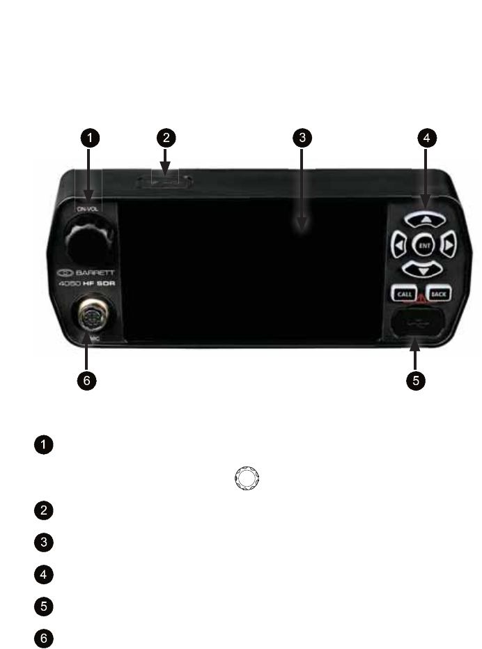
Transceiver Front Panel
Power button which combines switching the Transceiver on and off
with adjusting the volume.
This will be represented as throughout the manual.
USB / WiFi Socket
Touchscreen
Keypad
Mini USB Socket
Microphone socket
16
BARRETT 4050 HF SDR TRANSCEIVER - OPERATING AND INSTALLATION MANUAL
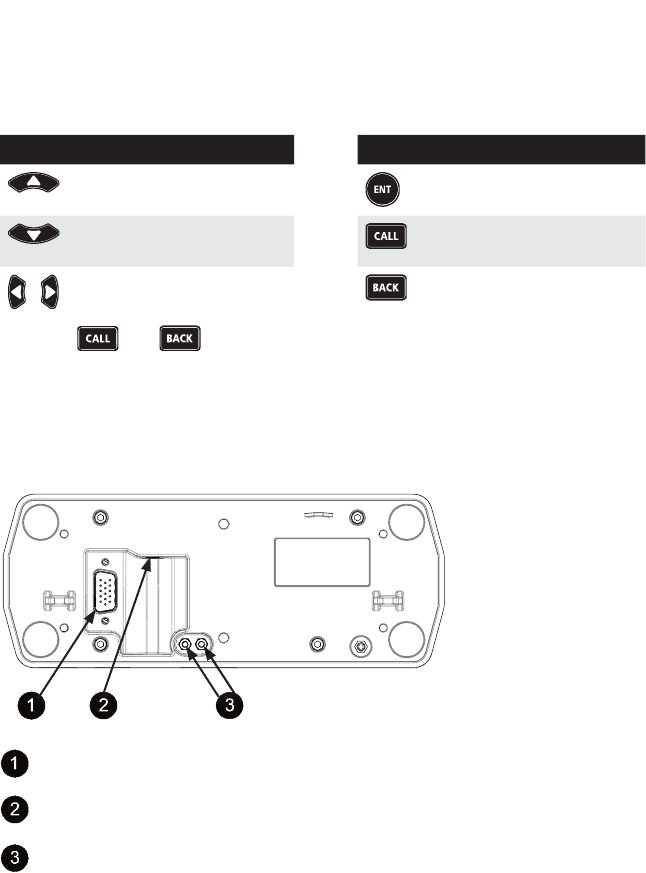
Keypad
There are seven keys on the keypad. Some keys have multiple functions
assigned to them depending on when or how long the key is pressed.
Key Function
Channel Up /
Scroll up
Channel Down /
Scroll down
Scroll left and right
Key Function
Enter /
Set a menu item
Make a call
Clear /
Back one step
Press the and buttons together to initiate an emergency call.
See page 26 for further information.
Transceiver Front Panel Rear View
15-way Transceiver plug for remote front panel interface cable
Speaker jack
Stand-offs (supplied) to enable the front panel to be detached and an
interface cable to be secured in position
The front panel may be detached from the Transceiver (for remote operation),
by pulling the front panel away from the Transceiver. A six metre cable may be
used to connect the front panel with the Transceiver’s 15-way connector.
The speaker jack is used to connect an external loudspeaker (P/N BCA40015).
17
BARRETT 4050 HF SDR TRANSCEIVER - OPERATING AND INSTALLATION MANUAL
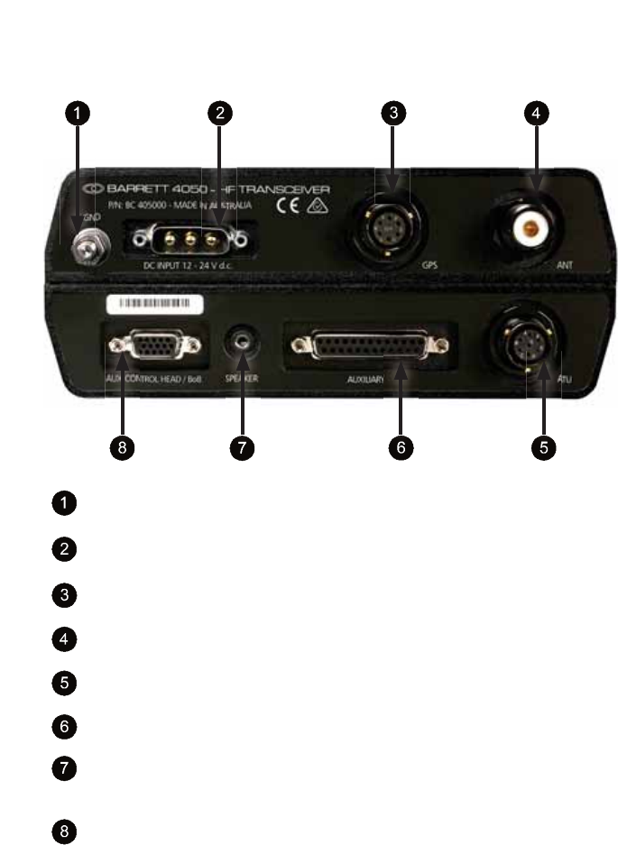
Transceiver Rear Panel
GND Use this stud to attach an earth connection.
For example, vehicle chassis.
DC INPUT
12 - 24 V d.c. Power input for use with the 4022 power supply
GPS Input for GPS receiver (P/N BCA40009) for vehicle
tracking / location applications.
ANT Main antenna socket
ATU Interface for Barrett automatic tuning mobile antenna
and marine automatic antenna tuners.
AUXILIARY 25-way auxiliary interface
SPEAKER Output for loudspeaker (P/N BCA40015)
AUX CONTROL
HEAD / BoB
This can be used to attach a secondary control head
(via a six metre cable) in addition to the front panel.
This can also be used to attach a Break out Box.
(see page 123)
18
BARRETT 4050 HF SDR TRANSCEIVER - OPERATING AND INSTALLATION MANUAL
Switching the Transceiver On / Off
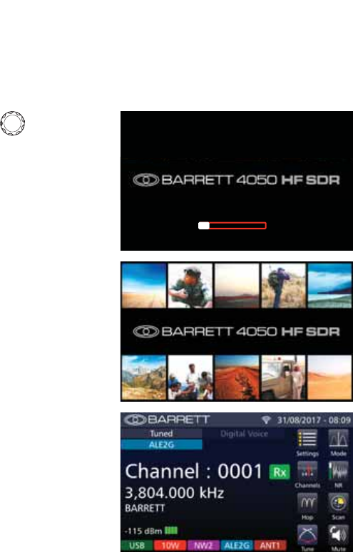
Switching the Transceiver On
Momentarily press to turn the
Transceiver on.
A progress bar displays beneath the
logo.
The Splash screen displays whilst the
keypad illuminates white, green, red,
and white.
The Home screen displays.
19
BARRETT 4050 HF SDR TRANSCEIVER - OPERATING AND INSTALLATION MANUAL
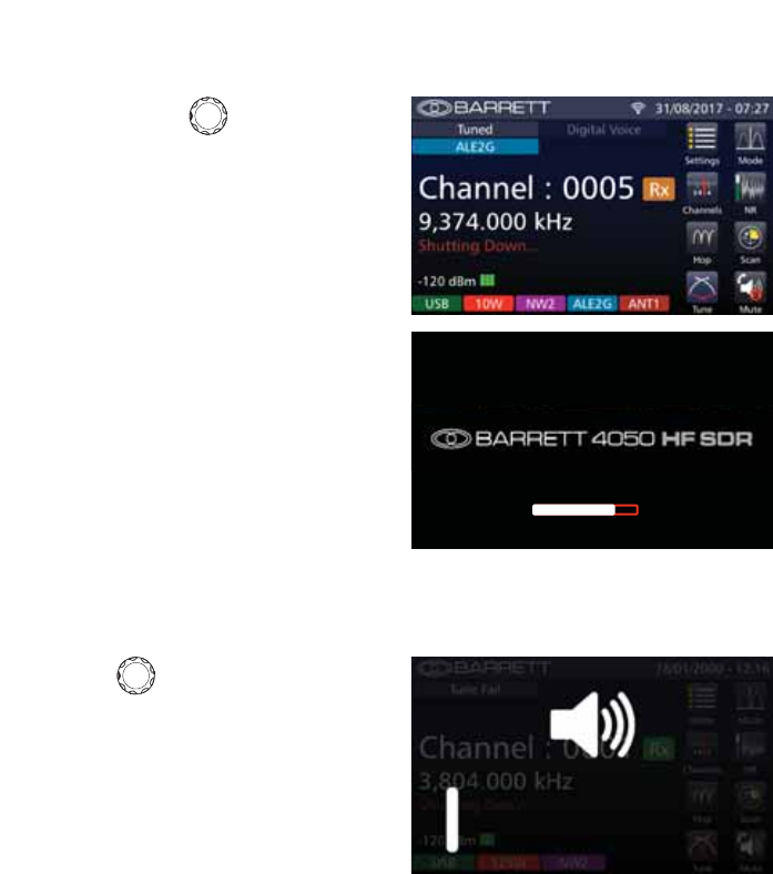
Switching the Transceiver Off
Press and hold for three seconds
to turn the Transceiver off.
The Transceiver returns to the Home
VFUHHQDQGEULHÁ\GLVSOD\VDUHGFRQ-
ÀUPDWLRQPHVVDJHWKDWWKHGHYLFHLV
“Shutting Down”.
A progress bar displays the status of
the shutting down process.
Volume
Rotate clockwise to increase
the volume and anti-clockwise to
decrease.
The rectangular icon beneath the
loudspeaker icon increases and de-
creases in length correlating with the
volume.
20
BARRETT 4050 HF SDR TRANSCEIVER - OPERATING AND INSTALLATION MANUAL
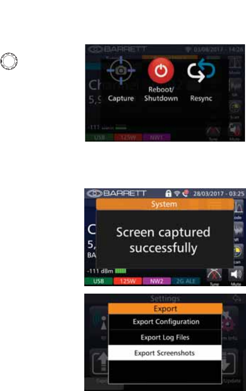
Power Button Menus
With the Transceiver switched on,
momentarily press to display the
Power Button menu.
Three options are available: Capture,
Reboot / Shutdown, and Resync.
These are described below.
Capture
Tap Capture from the Power Button
menu to perform a screen capture.
$FRQÀUPDWLRQPHVVDJHGLVSOD\VDQG
the screen capture is stored in the
Transceiver.
To transfer the screen capture from
the Transceiver to a PC, connect a
cable with a mini USB plug into the
Transceiver’s front USB port and plug
the other end with a standard USB
plug into a PC’s USB port.
From the Transceiver’s home screen,
select Menu > Export to display the
Export screen. Select Export screen-
shots to save the screen captures
from Transceiver to PC.
21
BARRETT 4050 HF SDR TRANSCEIVER - OPERATING AND INSTALLATION MANUAL
Reboot / Shutdown
Tap Reboot / Shutdown from the
Power Button menu to switch the
Transceiver off.
Tap and hold momentarily Reboot /
Shutdown to reboot the Transceiver.
The Transceiver returns to the Home
VFUHHQDQGEULHÁ\GLVSOD\VDUHGFRQ-
ÀUPDWLRQPHVVDJHWKDWWKHGHYLFHLV
“shutting down”.
Resync
Tap 5HV\QF from the Power Button menu to resynchronise the Transceiver data
with the control head.
Whilst resynchronising, the keypad illuminates green and the Busy status indi-
cator animates.
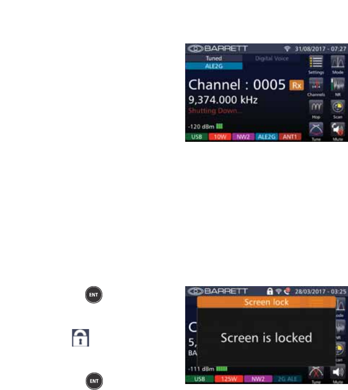
Locking and Unlocking the Screen
Press and hold IRUÀYHVHFRQGV
to lock the screen.
The following screen displays and the
locked icon is visible on the title
bar.
Similarly, with the screen locked,
press and hold IRUÀYHVHFRQGV
to unlock the screen.
22
BARRETT 4050 HF SDR TRANSCEIVER - OPERATING AND INSTALLATION MANUAL
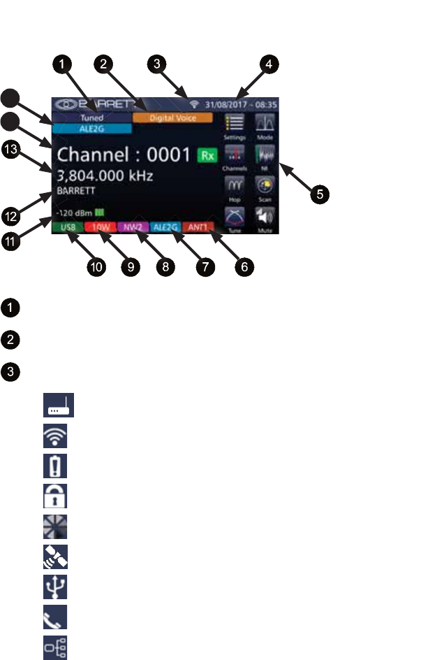
Display
14
15
Tune Status (page 134)
Digital Voice (page 138)
Status Indicators:
Access Point
WiFi
Low Voltage
Screen Lock
Busy
GPS
USB
Call Received
BoB Active
(page 120)
(page 118)
(page 21)
(page 148)
(Import page 127, Export page 114)
(page 31)
(page 123)

23
BARRETT 4050 HF SDR TRANSCEIVER - OPERATING AND INSTALLATION MANUAL
Date and Time (page 53)
Menus (page 49)
Antenna (page 64)
ALE (Channel) Status (page 60)
Selective Call Mode (page 64)
Transmit Power (page 63)
Mode (page 63)
Receive Strength Indicator
Channel Label (page 59)
Frequency (page 62)
14 Channel Number (page 62)
15 ALE (System) Status (page 102)
See page 115 for further information on Display Settings.
24
BARRETT 4050 HF SDR TRANSCEIVER - OPERATING AND INSTALLATION MANUAL
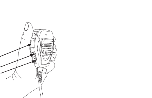
Using the Microphone
Up Button
Down Button
Press To Talk
(PTT) Button
When Using the Microphone:
1. Press and hold the PTT (transmit) button only while talking
2. Position the microphone close to your mouth
3. Speak clearly
4. 8VHWKHZRUGµRYHUµWRLQGLFDWHWKDW\RXKDYHÀQLVKHGVSHDNLQJDQGWKHQ
release the PTT (transmit) button.
Notes:
•
The Barrett 4050 has a transmit time-out facility. This facility (when pro-
grammed) allows the transmitter to be keyed in transmit mode with the PTT
(transmit) switch for a set time period, after which the Transceiver switches
to receive until the PTT (transmit button) is released and re-keyed. This facility
prevents the transmitter transmitting for long periods of time if, for example,
the microphone becomes jammed between seats in a vehicle causing the PTT
(transmit) switch to be held down. Enabling, disabling and changing the time
of the transmit timeout facility can be set either when programming the Trans-
ceiver or in the General Section of the Settings menu. See page 93.
•
7KHPLFURSKRQHXSGRZQEXWWRQVFDQEHFRQÀJXUHGIRUFKDQQHOFKDQJHRU
volume control functions either when programming the Transceiver or in the
General Section of the Settings menu. See page 53.

25
BARRETT 4050 HF SDR TRANSCEIVER - OPERATING AND INSTALLATION MANUAL
Programming Functions
The Transceiver may be programmed in two ways:
• By direct key entry through the front panel. See page 49.
Note: This facility may not be available if the network administrator has locked
it previously.
• %\LQVHUWLQJDWKXPEGULYHFRQWDLQLQJWKHDSSURSULDWHÀOHVLQWRWKH7UDQV-
ceiver’s USB socket. See page 127.
Program a New Channel from the Front Panel
Note: To program a channel from the front panel it is necessary to have this func-
tion enabled via the Barrett 4050 HF SDR Programming Software (P/N BCA40001).
Each channel requires the following parameters to be set:
• Channel Number
• Channel Label
• Rx Frequency
• Tx Frequency
• Channel Mode (USB, LSB, FSK, CW or AM)
• Channel Power (10, 30, 125 or 150 watt)
(Note: 150 W not available in Australia)
• Selcall Format (RFDS Alarm, OEM, CCIR, International or None)
• ALE Channel
• Antenna Select (Main or Auxiliary)
For information regarding adding a new channel, see page 61.
26
BARRETT 4050 HF SDR TRANSCEIVER - OPERATING AND INSTALLATION MANUAL
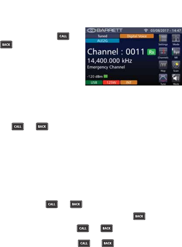
Emergency Calls
All Selcall emergency calls are
transmitted by pressing the
and buttons together for more
than two seconds. The emergency
call sequence commences when the
buttons are released.
The action of the emergency call depends on how the Transceiver has been pro-
grammed. For example:
• Selective Call alarm that only transmits on the currently selected channel
Transmits the emergency Selcall sequence once on each press of
the and buttons.
• Selective Call alarm that transmits and automatically changes to a selec-
tion of channels
Transmits the emergency Selcall sequence twice on each channel pro-
grammed as an emergency channel.
• Royal Flying Doctor Service (RFDS) alarm
Two-tone alarm 880 Hz + 1320 Hz continuous (Australian use only) –
alerts the Royal Flying Doctor Service on RFDS channels.
The RFDS alarm will continue transmitting for ten seconds even if you
have released the and buttons.
To cancel the RFDS alarm, press the PTT button or the button.
Note: A momentary press of the and buttons initiates an RFDS
alarm test mode which emits the audio tones but does not transmit them.
Another momentary press of the and buttons or PTT cancels the
RFDS alarm test mode.
,ID*36UHFHLYHULVÀWWHGDQGHQDEOHGWKH*36SRVLWLRQLVDOVRVHQWZLWKWKH
call.
Note: After the emergency call has been activated, there is no indication that an
alarm is being sent for security purposes.
27
BARRETT 4050 HF SDR TRANSCEIVER - OPERATING AND INSTALLATION MANUAL
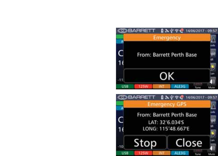
Receiving an Emergency Call
On receipt of an emergency Selcall, a
distinctive audio alarm is emitted and
the following message displayed.
If the Transceiver sending the emer-
JHQF\6HOFDOOLVÀWWHGZLWKD*36
receiver, the position will also be
displayed.

28
BARRETT 4050 HF SDR TRANSCEIVER - OPERATING AND INSTALLATION MANUAL
Barrett Selective Calling System
There are several different types of Selective Calling Systems available in addi-
tion to simple point-to-point RF communications.
The calling systems available for the Transceiver are listed below:
• International - A four and six digit Selective Call system, fully interoperable
with the UN format published in September 2004 and fully backwards
compatible with all previous Barrett four and six digit Selcall protocols.
• OEM - A four and six digit Selective Call system compatible with other
major HF manufacturers including those using encryption. Includes Selcall,
Telcall, Beacon Call, Emergency call, Pagecall and GPS call.
• &&,5$IRXUGLJLW6HOHFWLYH&DOOV\VWHPDVVSHFLÀHGE\&&,5
• ALE FED-STD-188 / MIL-STD-188-141B (option) - MIL-STD Automatic Link
Establishment system, refer to the Automatic Link Establishment (ALE)
section on page 100.
Summary of Calling Systems
Call Type International OEM CCIR
Emergency Call Yes Yes No
Beacon Call Yes Yes No*
Selcall Yes Yes Yes
Telcall Yes Yes Yes
Arinc Call Yes Yes Yes
Page Call (SMS) Yes Yes No
GPS Call (Data & Request) Yes Yes No
Secure Call Yes No No
Status Request Call Yes Yes No
Transceiver Lock Call Yes No No
* With Transceivers set to CCIR calling format, Beacon Call can be sent but will
be decoded as a Selcall by other Transceivers.

29
BARRETT 4050 HF SDR TRANSCEIVER - OPERATING AND INSTALLATION MANUAL
Selective Call - Selcall
Selcall (selective calling) is a digital signalling system based on the standard
CCIR-493 for use on HF networks. It is a type of squelch protocol used in
radio communications systems, in which transmissions include a brief burst of
sequential audio tones. Receivers that are set to respond to the transmitted
tone sequence will open their squelch, while others will remain muted.
Selcall Self IDs
Each station in an HF network can be assigned up to 14 different Self IDs of
ZKLFKWKHUHFDQEHDPL[WXUHRIIRXURUVL[GLJLW,'VLGHQWLÀFDWLRQ$VWDWLRQ
can be called using any of these Self IDs.
Selcall Decode
The Transceiver has the ability to decode both OEM and International Selcalls
on any channel programmed as a Selcall channel. However, the call must be
addressed to the relevant ID (OEM or International).
Calls for each format type will only be decoded if there is at least one Self ID of
that format programmed into the Transceiver Self ID group.
Selcall Transmit
6HOFDOOIRUPDWVLQWUDQVPLWDUHFKDQQHOVSHFLÀF)RUH[DPSOHRQO\FDOOW\SHV
programmed for the channel are permitted. This means International and CCIR
format calls can only be sent on channels that are programmed as International
or CCIR Selcall channels. OEM calls can only be sent on channels that are pro-
grammed as OEM Selcall channels.
Selective Call - Telcall
Telcall uses this digital Selective Call system to send a telephone number from a
station on an HF network to a base station equipped with a telephone inter-
connect unit to initiate phone calls onto the PSTN.
1RWH)RU6HOFDOODQG7HOFDOOIXQFWLRQVWRRSHUDWHWKH7UDQVFHLYHUPXVWEHÀWWHGZLWK
the Selcall or Telcall option and the channels enabled for Selcall operation.
If Automatic Link establishment (ALE) is in use, refer to the Automatic Link
Establishment (ALE) section on page 100.

30
BARRETT 4050 HF SDR TRANSCEIVER - OPERATING AND INSTALLATION MANUAL
Special Notes for the OEM Selective Call Protocol
Four and six digit OEM calls will only be decoded by other Barrett Transceivers
ÀWWHGZLWKWKH2(06HOFDOOSURWRFRORURWKHUPDQXIDFWXUHU·V7UDQVFHLYHUVWKDW
use encryption.
Four and six digit GPS and Status data calls use the OEM privacy key to encrypt
the data. If this eight digit key has not been programmed by the Barrett 4050
HF SDR Programming Software (P/N BCA40001), a default privacy key of
99999999 is automatically used for transmission.
Six digit Page calls also use the privacy key but unlike the other calls, the user
has the option to manually enable or disable the privacy key. When disabled,
the data is sent as plain text.
Emergency GPS calls are automatically sent as plain text (four and six digit).
Station ID Ranges
The standard Selcall system accommodates four and six digit networks.
Station IDs range from 000000 to 999999 inclusive (the destination ID must be
either four or six digits long).
31
BARRETT 4050 HF SDR TRANSCEIVER - OPERATING AND INSTALLATION MANUAL
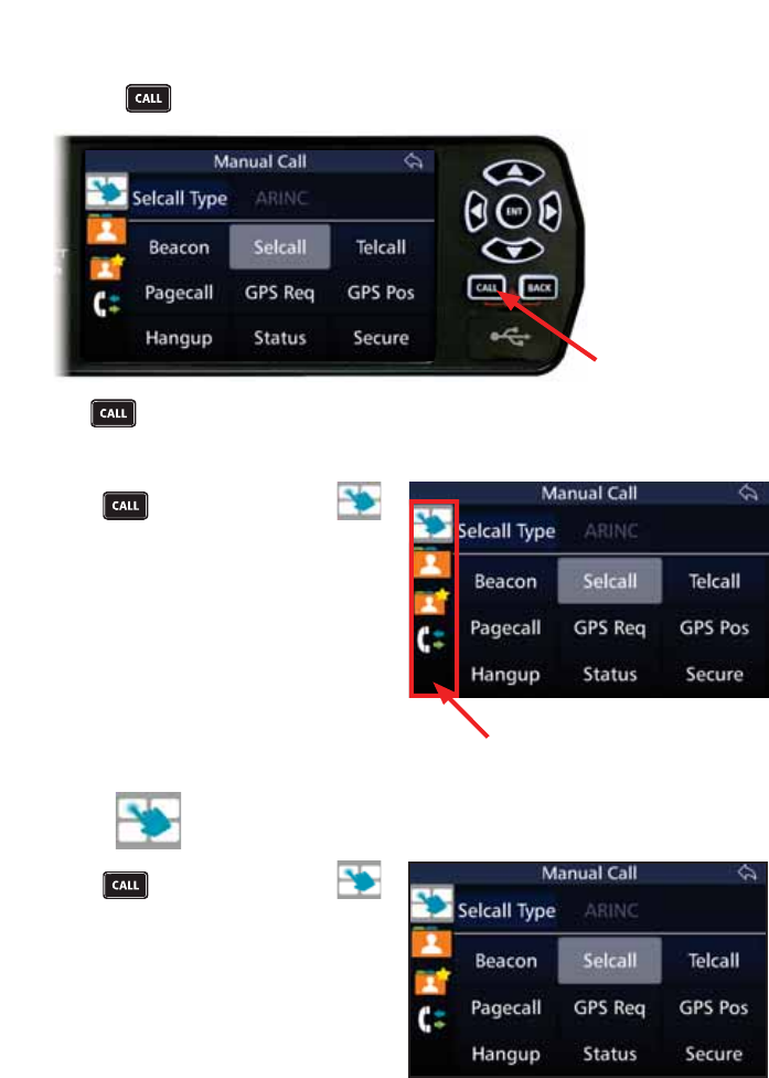
Call Key
Use the key to quickly invoke a call.
Call Key
The key is located in the lower left of the Transceiver’s keypad, above the
mini USB socket.
Press and if necessary tap
to display the Manual Call screen.
The Call screen comprises two areas.
The narrow left hand area has four
menu options. The broader right
hand area displays the screens for
each of the menu options.
The Call menu options are: Call Type,
Contacts, Favourites, and Call History.
These options are described below. Menu Options for calls
Call Type
Press and if necessary tap
to display the Manual Call screen.
From this screen choose the type of
call to be made. The choices are: Bea-
con, Selcall, Telcall, Pagecall, GPS Req,
GPS Pos, Hangup, Status and Secure.
These are described below.
32
BARRETT 4050 HF SDR TRANSCEIVER - OPERATING AND INSTALLATION MANUAL
Beacon Call
A Beacon Call checks for the best channel to use between two stations. It
allows the Operator to determine the signal quality between their station and
the station they want to call on a particular channel, but without actually alert-
ing the station they are doing so.
When a Beacon Call is sent to another station, and if the channel being used is
open, the remote station sends back a distinctive four-tone revertive signal. The
Operator can judge the quality of the channel for communications purposes by
the strength and clarity of this distinctive tone. Using Beacon Calls on several
available channels will determine which channel is best to use either subse-
quent Selcalls or Telcalls.
Note: both stations must be programmed for Selcall or Telcall operation.
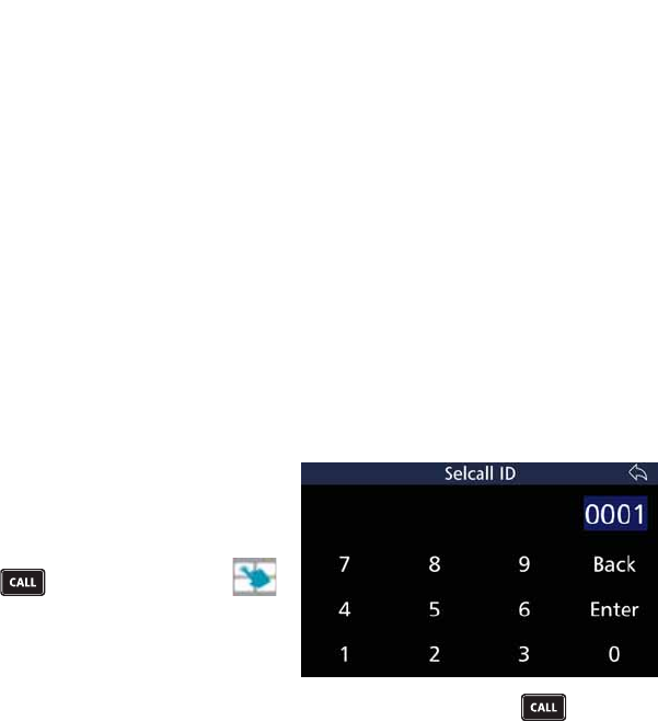
Send a Beacon Call
/LVWHQIRUWUDIÀFRQ\RXUVHOHFWHG
FKDQQHO,IWUDIÀFLVKHDUGFKDQQHO
is occupied), select another channel
and try again.
Press and if necessary tap
to display the Manual Call screen.
Tap %HDFRQ to display the Selcall ID
screen.
Use the keyboard to type the Selcall ID, then tap Enter or press and wait
for the Beacon Call to be sent. Listen for the distinctive four tone revertive
signal from the station you have called. If the revertive call is not heard, or it
ZDVGLIÀFXOWWRKHDUWU\DQRWKHUFKDQQHODQGUHSHDWWKHSURFHVVXQWLOWKHEHVW
channel is found.
Receive a Beacon Call
When a Transceiver receives a beacon request call, it responds by transmitting
the Beacon Call revertive tones. No indications occur on the Transceiver. Beacon
Calls are not saved in the Selcall history buffer.
33
BARRETT 4050 HF SDR TRANSCEIVER - OPERATING AND INSTALLATION MANUAL
Selcall
Selcall is a digital signalling system based on standard CCIR-493 for use on
HF networks. Each station in an HF network can be assigned Self IDs of which
WKHUHFDQEHDPL[WXUHRIIRXURUVL[GLJLW,'VLGHQWLÀFDWLRQ7KHVWDWLRQFDQEH
called using any of these Self IDs.
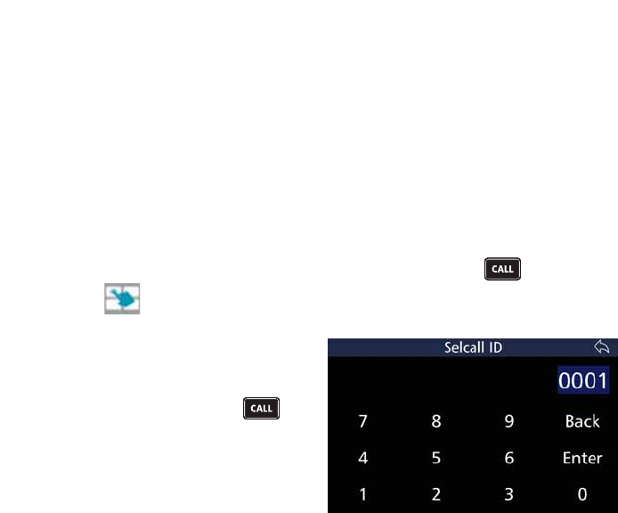
Send a Selcall
Select the channel you want to send the Selcall on. (Use a Beacon Call initially
to select the best channel - see page 32.)
/LVWHQIRUWUDIÀFRQWKDWFKDQQHO,IWUDIÀFLVQRWKHDUGSUHVV and if neces-
sary tap to display the Manual Call screen.
Tap 6HOFDOO to display the Selcall ID
screen.
Use the keyboard to type the Selcall
ID, then tap Enter or press and
wait for the Selective Call to be sent.
Listen for revertive tone from the
called station that indicates the call
was successful.
,IWKHUHYHUWLYHWRQHLVQRWKHDUGRULWZDVGLIÀFXOWWRKHDUWU\DQRWKHUFKDQQHO
and repeat the process until a good channel is found.
If a revertive tone is heard but you receive no verbal response from the station,
it may be because the Operator is unavailable at the time.
Receiving a Selcall Directed to Your Transceiver
Note: To receive a Selcall your Transceiver must be programmed for Selective Call
(Selcall) and where multiple channels are in use the scan function should be acti-
vated.
34
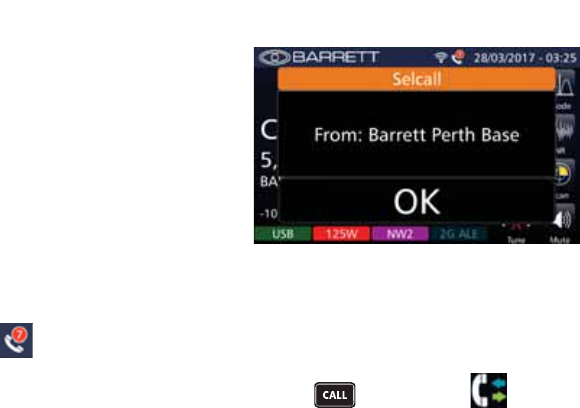
BARRETT 4050 HF SDR TRANSCEIVER - OPERATING AND INSTALLATION MANUAL
When you receive a Selcall, your
station sends a revertive tone (to alert
the calling station that its call was
received), an audible alarm sounds,
the mute (squelch) (if selected) opens
and the display shows who the call
is from.
The audible alarm will sound for 60 seconds and then time out. To cancel the
alarm before the time out period and to acknowledge the call, press the PTT
button or tap Ok. When the audible alarm times out, the call received icon
displays
p
and a periodic audio reminder is emitted.
For details of previously received Selcalls, press and then tap to dis-
play the Call History screen. Refer to the Call History section on page 47.
Receiving Allcalls, Group Calls and Sub-group Calls
Stations can send a Selective Call that will alert different groupings of mobiles
as follows:
In four digit format
Allcall - A station sending X000 will be received by stations X000 - X999 (up to
890 stations*)
Group call - A station sending XX00 will be received by stations XX00 - XX99
(up to 89 stations*)
Sub-group call - A station sending XXX0 will be received by stations XXX0 -
XXX9 (up to 9 stations*)
In six digit format
Allcall - A station sending XXX000 will be received by stations XXX000 -
XXX999 (up to 890 stations*)
Group call - A station sending XXXX00 will be received by stations XXXX00 -
XXXX99 (up to 89 stations*)
Sub-group call - A station sending XXXXX0 will be received by stations XXXXX0
- XXXXX9 (up to 9 stations*)

35
BARRETT 4050 HF SDR TRANSCEIVER - OPERATING AND INSTALLATION MANUAL
* If using the group call system, stations cannot be programmed to have Self
IDs with last digits 000,00,0 as if you tried to call them a group call would
occur.
Receiving an Allcall, Group Call or Sub-group Call
When you receive an Allcall, Group Call or Sub-group call, an audible alarm
sounds, the mute (squelch) (if selected) opens and the display shows the call
type.
In all group calls the audible alarm will sound for 60 seconds and then time
out. To cancel the alarm before the time out and to acknowledge the call, press
the PTT button or tap Ok. When the audible alarm times out, the call received
envelope icon displays.
For details of previously received Selcalls, press and then tap to dis-
play the Call History screen. Refer to the Call History section on page 47.
Telcall
Telcall uses this digital Selective Call system to send a telephone number on
an HF network. Telcalls are primarily used to send to stations equipped with a
telephone interconnect unit to initiate phone calls onto the PSTN.
1RWH)RU6HOFDOODQG7HOFDOOIXQFWLRQVWRRSHUDWHWKH7UDQVFHLYHUPXVWEHÀWWHGZLWK
the Selcall or Telcall option and the channels enabled for Selcall operation.
If Automatic Link Establishment (ALE) is in use, refer to the ALE section on
page 100.
Send a Telcall
Select the channel you want to send the Telcall on. (Use a Beacon Call initially
to select the best channel - see page 32.)
/LVWHQIRUWUDIÀFRQWKDWFKDQQHOLIWUDIÀFLVQRWKHDUGSUHVV and if neces-
sary tap to display the Manual Call screen.
36
BARRETT 4050 HF SDR TRANSCEIVER - OPERATING AND INSTALLATION MANUAL
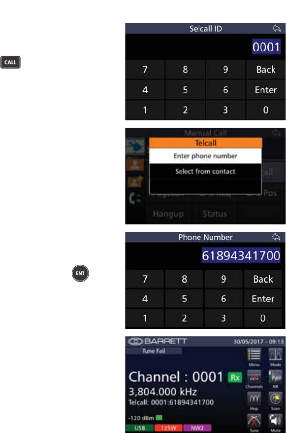
Tap 7HOFDOO to display the Selcall ID
screen.
Type the Selcall ID, then tap Enter
or press to display the Telcall
screen.
From the Telcall screen, tap either
Enter phone number or
6HOHFWIURPFRQWDFW.
If Enter phone number was selected,
the Phone Number screen displays.
Type the phone number using the
keyboard and either press or tap
Enter to return to the home screen
and send the Telcall.
The home screen momentarily dis-
plays the Telcall ID.
37
BARRETT 4050 HF SDR TRANSCEIVER - OPERATING AND INSTALLATION MANUAL
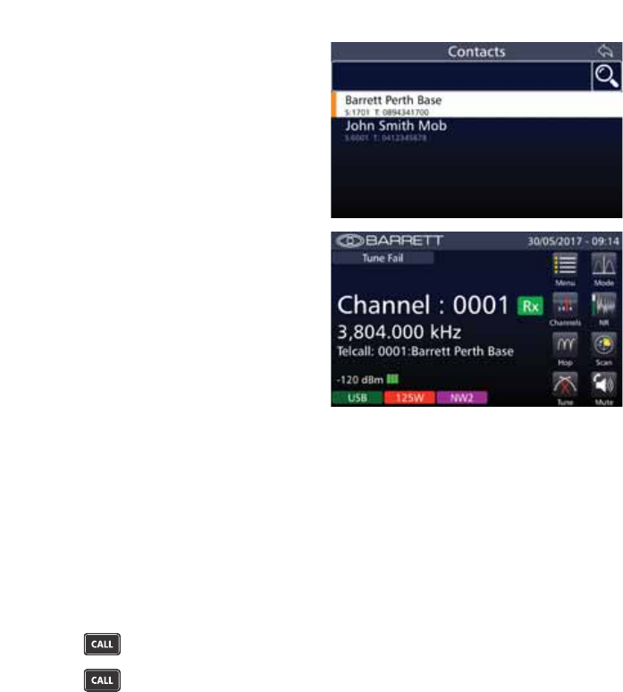
If Select from Contact was selected,
the Contacts screen displays.
Tap the selected contact to return to
the home screen and send the Telcall.
The home screen momentarily dis-
plays the Telcall ID.
Listen for revertive tone from the called station that indicates the call is suc-
cessful. If the revertive tone is not heard, try another channel and repeat the
process.
If the destination station is connected to a Telephone Interconnect, when the
call is successful, wait for telephone connection to be made and then proceed
with the call. When the call is complete, or if the line is busy, send a Hang-Up
call (see page 42).
Last Number Redial
Press four times and the last telephone number sent displays.
Press once more and the Telcall sequence will be re-sent.
Receive a Telcall
Note: To receive a Telcall your Transceiver must be programmed with a Self ID and
where multiple channels are in use the scan function should be activated.
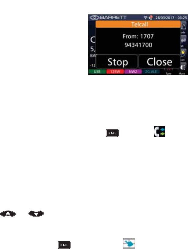
When you receive a Telcall, your station sends a revertive call (to alert the
calling station that its call was received), an audible alarm sounds, the mute
(squelch) (if selected) opens and the Telcall screen displays.
38
BARRETT 4050 HF SDR TRANSCEIVER - OPERATING AND INSTALLATION MANUAL
The Telcall screen shows the Selcall ID
and telephone number of the caller.
Tap Stop to stop the audible alarm
but maintain the Telcall screen.
Tap Close To close the Telcall screen.
The audible alarm will sound for 60 seconds and then time out. To cancel
the alarm before the time out period and to acknowledge the call, press the
PTT button or tap either Stop or Close (described above). When the audible
alarm times out, the call received Envelope icon displays and a periodic audio
reminder is emitted.
After the timeout, the call received icon displays.
For details of previously received Telcalls, press and then tap to dis-
play the Call History screen. Refer to the Call History section on page 47.
Pagecall
Pagecall (SMS) allows messages of up to 32 characters in International format,
or 64 characters in OEM format to be sent or received to and from other Trans-
ceivers with Pagecall facilities.
Send a Pagecall
Use and to select the channel you want to send the Pagecall on
DQGOLVWHQIRUWUDIÀFRQWKDWFKDQQHO
Note: Use a Beacon Call initially to select the best channel - see page 32.
,IWUDIÀFLVQRWKHDUGSUHVV and if necessary tap to display the Man-
ual Call screen.
39
BARRETT 4050 HF SDR TRANSCEIVER - OPERATING AND INSTALLATION MANUAL
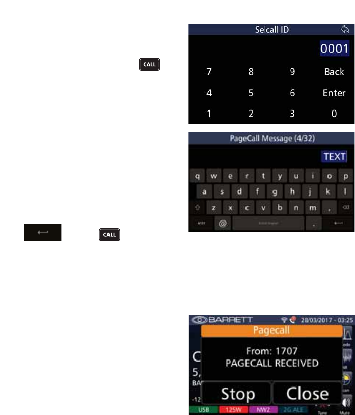
Tap 3DJHFDOO to display the Selcall ID
screen.
Use the keyboard to type the Selcall
ID, then tap Enter or press to
display the PageCall Message screen.
Type your message using the alpha
numeric keys. The numbers in the
parenthesis indicate how many char-
acters you have used / total number
of characters allowed.
Use up to 32 characters for an inter-
national Selcall and 64 for OEM.
Once the message is completed, tap
or press to send.
Receive a Pagecall
When a Pagecall is received, an audible alarm sounds, any mute is disabled and
the Pagecall screen displays
The Pagecall screen shows the Selcall
ID and message.
Tap Stop to stop the audible alarm
but maintain the Pagecall screen.
Tap Close To close the Pagecall
screen.
The audible alarm will sound for 60 seconds and then time out. To cancel
the alarm before the time out period, and to acknowledge the call press the
PTT button or tap either Stop or Close (described above). When the audible
alarm times out, the call received Envelope icon displays and a periodic audio
reminder is emitted.
When the audible alarm times out, the call received Envelope icon displays.
40
BARRETT 4050 HF SDR TRANSCEIVER - OPERATING AND INSTALLATION MANUAL
For details of previously received Selcalls, press and then tap to dis-
play the Call History screen. Refer to the Call History section on page 47.
GPS Req
Use this option to request another station’s GPS position.
Use and to select the channel you want to send the GPS request
FDOORQDQGOLVWHQIRUWUDIÀFRQWKDWFKDQQHO
Note: Use a Beacon Call initially to select the best channel - see page 32.
,IWUDIÀFLVQRWKHDUGSUHVV and if necessary tap to display the Man-
ual Call screen.
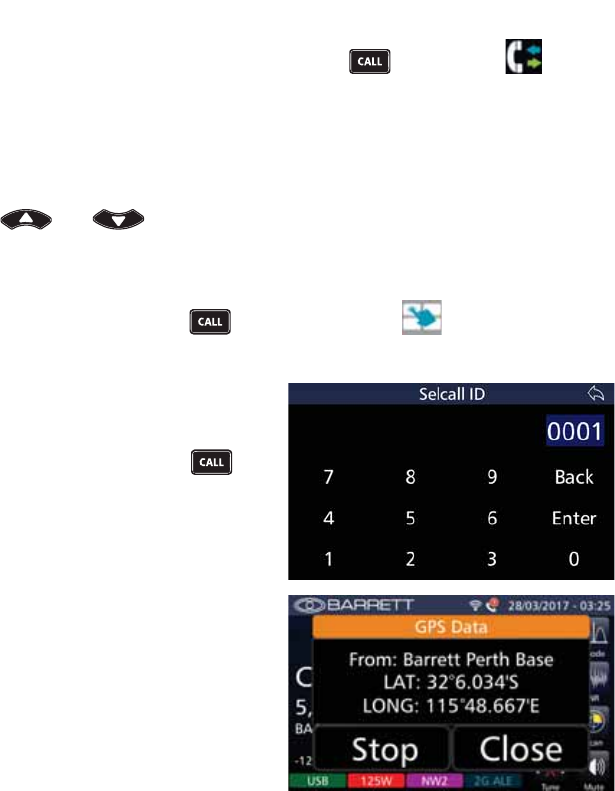
Tap GPS Req to display the Selcall ID
screen.
Use the keyboard to type the Selcall
ID, then tap Enter or press .
The station you called returns its
position.
The GPS Data screen displays the
caller’s Selcall Alias (if available or
alternatively the Selcall ID), and
the caller’s Latitude and Longitude
position.
To stop the sounding alarm but main-
tain the GPS Data display, tap Stop.
To remove the GPS Data display tap
Close.
41
BARRETT 4050 HF SDR TRANSCEIVER - OPERATING AND INSTALLATION MANUAL
However, the following error messages may be displayed:
• GPS Unresponsive at Remote Station
The GPS unit is not providing data to the remote Transceiver.
• GPS Not Fitted at Remote Station
7KHUHLVQR*36UHFHLYHUÀWWHGWRWKHUHPRWH7UDQVFHLYHU
• No Response
There was no response from the remote station.
GPS Pos
Use this option to send your GPS position to another station.
1RWH7KHEXLOWLQ*36LQWHUIDFHRSWLRQPXVWEHÀWWHGDQGWKH*36UHFHLYHU
(
P/N BCA40009
) must be connected and receiving position information when using
the GPS call option.
Use and to select the channel you want to send the GPS call on
DQGOLVWHQIRUWUDIÀFRQWKDWFKDQQHO
Note: Use a Beacon Call initially to select the best channel - see page 32.
,IWUDIÀFLVQRWKHDUGSUHVV and if necessary tap to display the Man-
ual Call screen.
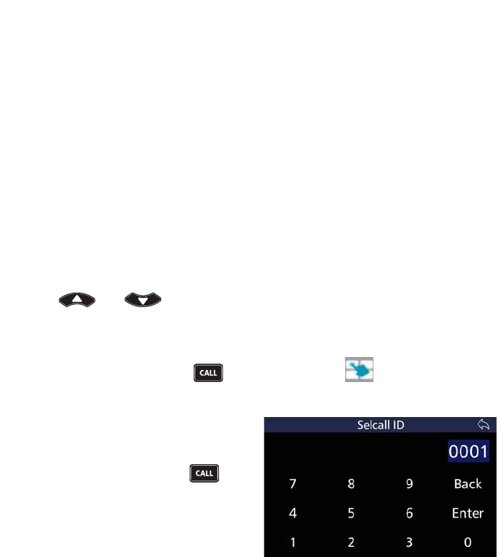
Tap GPS Pos to display the Selcall ID
screen.
Use the keyboard to type the Selcall
ID, then tap Enter or press to
transmit your GPS position.
:DLWIRUWKHUHYHUWLYHWRQHIURPWKHUHPRWHVWDWLRQWRFRQÀUPWKHFDOOZDV
received. If revertive tone is not heard, repeat the process or change to another
channel and repeat the process.
Note: If the display indicates that the GPS is unavailable, you cannot select the
Selective Call function GPS data.
42
BARRETT 4050 HF SDR TRANSCEIVER - OPERATING AND INSTALLATION MANUAL
Hangup
When a call to a telephone interconnect base station has completed or a secure
call link is complete, the Operator should ‘hang-up’ by sending a hang-up code
to a telephone interconnect.
Note: If the hang up call is unsuccessful for any reason, the telephone interconnect
will time out and hang-up automatically.
Press and if necessary tap to display the Manual Call screen.
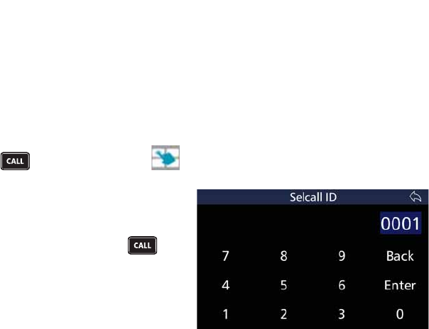
Tap Hangup to display the Selcall ID
screen.
Use the keyboard to type the Selcall
ID, then tap Enter or press
When the hang-up Selcall has com-
pleted transmitting, listen for hang-
XSUHYHUWLYHWRQHZKLFKFRQÀUPVWKDW
the hang-up was successful.
When hanging up a telephone in-
terconnect call, the hang-up process
may be repeated until a revertive
tone is heard.
If the hang-up call is unsuccessful
when ending a secure call, only the
Transceiver that sent the hang-up call
will exit secure mode. Repeating the
hang-up call will not hang-up the
remote end.
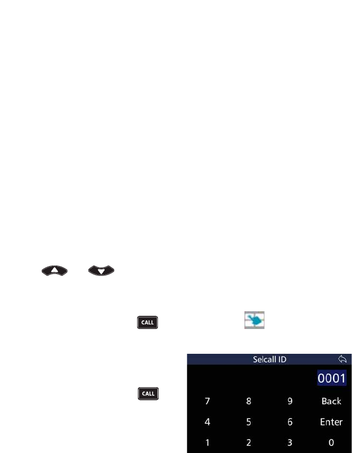
43
BARRETT 4050 HF SDR TRANSCEIVER - OPERATING AND INSTALLATION MANUAL
Status
A Status call allows the operational status parameters of any Barrett Trans-
FHLYHUÀWWHGZLWK6HOFDOOWREHDFFHVVHG7KLVVWDWXVLVVHQWIURPWKHUHPRWH
Transceiver as a Selcall with the status information embedded within the Selcall
structure. Information retrieved for remote diagnosis of Transceiver perfor-
mance includes:
• Selcall ID
• Receive state battery voltage
• Last transmit state battery voltage
• Signal strength indication of received status request Selcall
• Forward power output level
• VSWR of the antenna
• Temperature
• Selcall ID of the last radio called.
Requesting Another Station’s Status
Use and to select the channel you want to send the Status
UHTXHVWFDOORQDQGOLVWHQIRUWUDIÀFRQWKDWFKDQQHO
Note: Use a Beacon Call initially to select the best channel - see page 32.
,IWUDIÀFLVQRWKHDUGSUHVV and if necessary tap to display the Man-
ual Call screen.
Tap Status to display the Selcall ID
screen.
Use the keyboard to type the Selcall
ID, then tap Enter or press to
transmit the status request and wait
for the remote station to return its
status data.
If a reply is not received, either repeat the process or change the channel and
repeat the process.
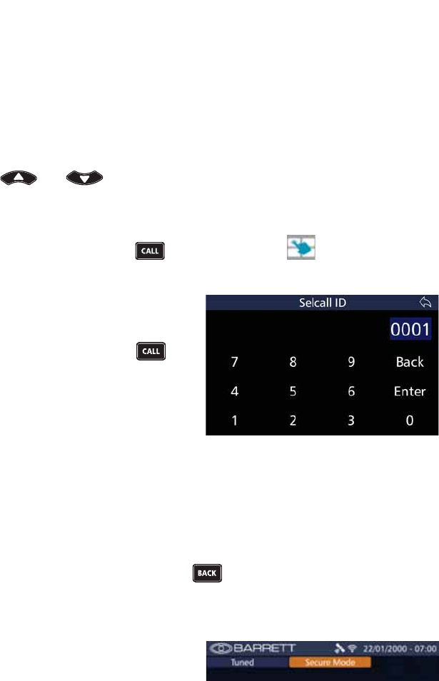
44
BARRETT 4050 HF SDR TRANSCEIVER - OPERATING AND INSTALLATION MANUAL
Secure
Secure Calls can only be made on channels programmed with International
Format Selcall.
A Person to Person(s) Secure Call allows a secure voice connection to be made
between two or more stations.
Note: The 4 digit secure call code must be the same for both stations. See Secure
Call Code on page 113.
Use and to select the channel you want to set the secure link to
DQGOLVWHQIRUWUDIÀFRQWKDWFKDQQHO
Note: Use a Beacon Call initially to select the best channel - see page 32.
,IWUDIÀFLVQRWKHDUGSUHVV and if necessary tap to display the Man-
ual Call screen.
Tap 6HFXUH to display the Selcall ID
screen.
Use the keyboard to type the Selcall
ID, then tap Enter or press and
wait for the Selective Call to be sent..
Note: To make a secure call to multiple
stations, use a group call ID encom-
passing the required stations.
Listen for the secure call revertive tone from the called station which indicates
the call was successful.
Note: The secure call revertive tone has a different sound to the revertive tones of
the other call types.
,IUHYHUWLYHWRQHLVQRWKHDUGRULWZDVGLIÀFXOWWRKHDUWU\DQRWKHUFKDQQHODQG
repeat the process until a good channel is found.
To exit out of secure call mode, press or send a “Hangup” call.
Note: Revertive tones will not be heard if using a group call code to call multiple
stations.
6HFXUHPRGHLVFRQÀUPHGDQGLQGL-
cated beneath the title bar.
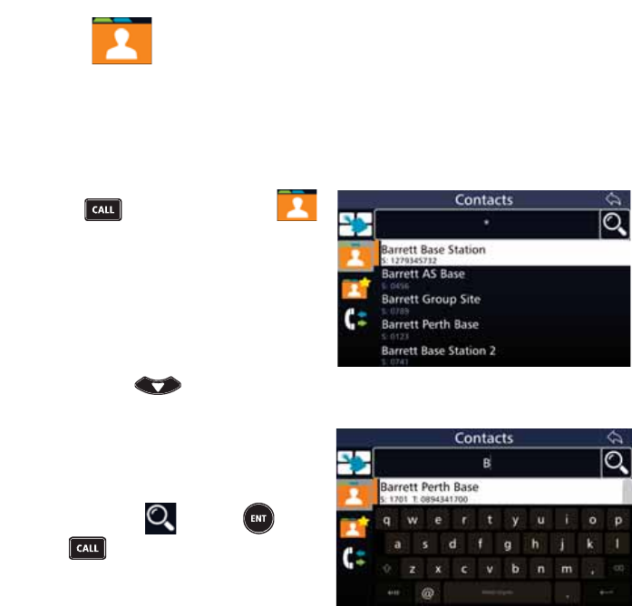
45
BARRETT 4050 HF SDR TRANSCEIVER - OPERATING AND INSTALLATION MANUAL
Contacts
Selective call functions require Station IDs to be entered when making a call.
Contacts allow frequently used Station IDs to be called easily.
This section describes how to use the Contact list, Favourites and Call History.
See page 67 for information on adding, editing and deleting contacts.
Press and if necessary tap
to display the Contacts screen.
A list of contacts displays.
From the Contacts screen either:
• Select a contact from the Contact
list. Scroll down the list to reveal
more contacts by either swiping
down on the touch screen or
pressing and then tapping
the desired contact.
• Search for Contacts by tapping
WKH&RQWDFWVÀHOGWRUHYHDODNH\-
board. Tap the search criteria into
WKH&RQWDFWVÀHOG
Either tap or press or
to display the results of the
search.
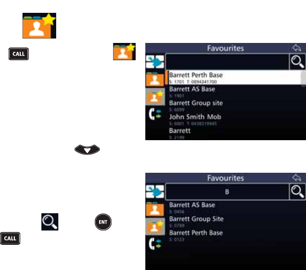
46
BARRETT 4050 HF SDR TRANSCEIVER - OPERATING AND INSTALLATION MANUAL
Favourites
Press and if necessary tap
to display the Favourites screen.
A list of favourite contacts displays.
From the Favourites screen either:
• Select a contact from the favour-
ites list. Scroll down the list to
reveal more contacts by either
swiping down on the touch
screen or pressing and
then tapping the desired contact.
• Search for Contacts by tapping
WKH)DYRXULWHVÀHOGWRUHYHDOD
keyboard. Tap the search criteria
LQWRWKH)DYRXULWHVÀHOG
Either tap or press or
to display the results of the
search.
To add a contact, see page 67.
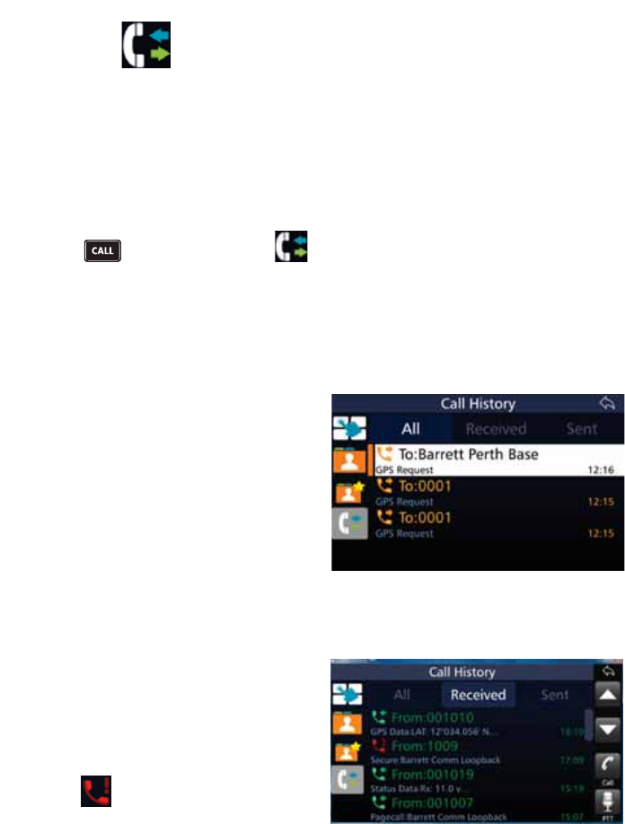
47
BARRETT 4050 HF SDR TRANSCEIVER - OPERATING AND INSTALLATION MANUAL
Call History
Whenever a Selcall, Telcall, Allcall, Group call, Sub-group call, Pagecall, Status-
call, GPS or Emergency call is received or transmitted, its details are held in a
ÀUVWLQÀUVWRXWFDOOKLVWRU\EXIIHU
All received calls are stored in the Received tab.
All transmitted calls are stored in the Sent tab.
Each history buffer can store up to 100 entries.
Press and if necessary tap to display the Call History screen.
The Call History screen has three tabs: All, Received, and Sent. These are
described below.
All
This tab displays a list of all calls sent
and received.
The list also details the Selcall ID and
the times of the calls.
Received
This tab lists all types of Selcalls that
have been received, viewed and
stored for future reference.
From the Call History screen, tap
Received to display a list of all calls
received.
The icon indicates a missed call.
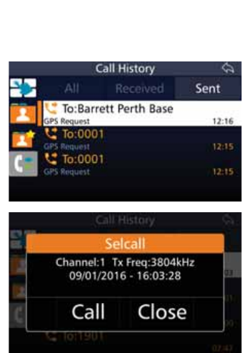
48
BARRETT 4050 HF SDR TRANSCEIVER - OPERATING AND INSTALLATION MANUAL
Sent
This tab lists all types of Selcalls that
have been transmitted.
From the Call History screen, tap
Sent to display a list of all calls sent.
Select the call displayed in any of
the three Call History tabs to display
the channel number, frequency, date
and time.
Tap Call to proceed with a call to
the selected number.
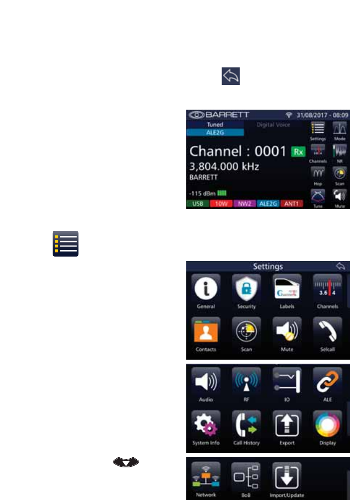
49
BARRETT 4050 HF SDR TRANSCEIVER - OPERATING AND INSTALLATION MANUAL
Menus
To navigate through the menus, either use swiping motions on the touch
screen or use the keypad (described on page 16).
To return to a previous screen, you may also tap located in the top right
hand corner of each screen.
The Transceiver’s home screen dis-
plays the following menus:
• Settings
• Channels
• Hop
• Tune
• Mode
• NR
• Scan
• Mute
These menus are described in the
following sections.
Settings
Select the Settings menu to display
the Settings screen which enables
access to the following sub menus:
• General
• Security
• Labels
• Channels
• Contacts
• Scan
• Mute
• Selcall
• Audio
• RF
• IO
• ALE
• System Info
• Call History
• Export
• Display
• Network
• BoB (if connected)
• Import/Update
To reveal subsequent pages of sub
menus, either swipe down on the
touch screen or press .
These sub menus are described in the
following sections.
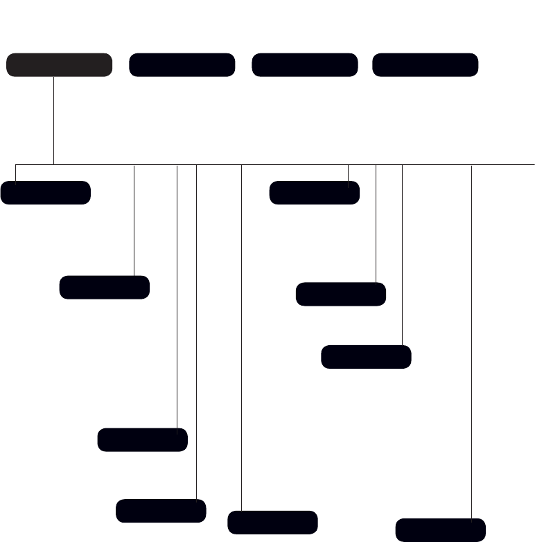
50
BARRETT 4050 HF SDR TRANSCEIVER - OPERATING AND INSTALLATION MANUAL
Menu Map
Settings
General
Labels
Channels Contacts
Scan
Mute
Selcall
Audio
Channels Hop Tune
Transceiver Name
Mic Up/Down Keys
Date and Time
BITE Test
Language
Select a Channel Invoke Tuning Sequence
Initiate Hopping
Audio in Tx
Preamble Time
Default Int Selcall ID (4 digits)
Default Int Selcall ID (6 digits)
OEM Privacy Key
OEM Selcall ID (4 digits)
OEM Selcall ID (6 digits)
Selcall Networks
GPS Broadcast Enable
Transceiver Lock
Beep Level
Alarm Audio Level
Ring Tones
5[&RQÀJXUDWLRQ
7[&RQÀJXUDWLRQ
Audio Bandwidth
Line Audio
Line Follows DV
Line Out Level
Line In Level
Audio Record
Scan Rate
Dwell Time
Resume Time
Table Selection
Edit Scan Tables
Syllabic Sensitivity
Signal Strength Level
Delete
Edit
Add
Delete
Edit
Add
Number
Label
Rx Frequency
Tx Frequency
Mode
Tx Power
Selcall Format
ALE Channel
Antenna Socket
Delete
Edit
Add
First Name
Surname
ID Type
ALE 2G Alias
ALE 3G Alias
Email Address
Phone Number
Favourite
Hopping PIN
Frequency Hop Rate
OEM Secure Type
OEM Secure Key
Secure Digital Voice Key
Secure Data Key
Secure Calls Hop Rate
Secure Call Code
TC2 Programming Mode
Security

51
BARRETT 4050 HF SDR TRANSCEIVER - OPERATING AND INSTALLATION MANUAL
Call History
IO
System Info
Network
BoB
RF
ALE
Display
Import / Update
Mode NR Scan Mute
Invoke Scanning
Rx Preamp
Tx Over Beep
Transmit Timeout
Noise Blanker
Tx Power Level
AGC Hang
Broadcast Filter
Preselector
WiFi Operation Mode
WiFi Access Point
BoB Name
Network Settings
Network Status
,PSRUW&RQÀJXUDWLRQ
Program Firmware
Level of Display Backlight
Backlight Timeout
Display Timeout Behaviour
Transmit Meter Mode
Receive Meter Mode
Temperature Units
System Status
Version Information
Transceiver Options
4050 Serial Number
ALE State 2G
Preset Map
Response Control
Sounding Control
Sounding Address
LQA Exchange
LQA Averaging
LQA Decay Rate
Threshold Test
SINAD Threshold
BER Threshold
RS 232 Out
RS232 Baud Rate
Ext Alarm Type
Antenna 1 Type
Antenna 2 Type
USB
LSB
FSK
CW
AM
Off
Low
Medium
High
Audio Mute
SSL Mute
Selcall Mute
Mute Disabled
Export
ALE State 3G
Voice Link Timeout
Data Link Timeout
LQA Averaging
LSU Mode
ALE 3G Channels
Ale 3G Address
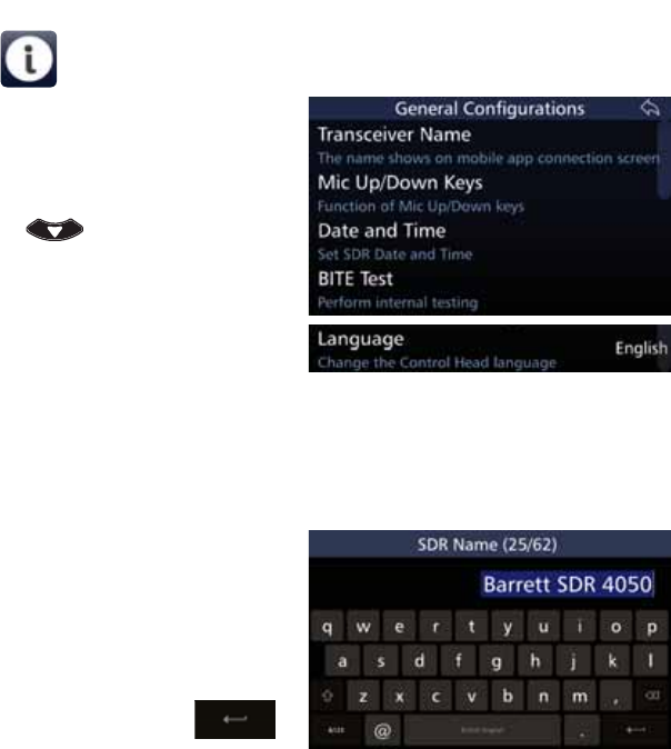
52
BARRETT 4050 HF SDR TRANSCEIVER - OPERATING AND INSTALLATION MANUAL
General
Select the General menu to display
the *HQHUDO&RQÀJXUDWLRQVVFUHHQ
$OLVWRILWHPVWKDWPD\EHFRQÀJXUHG
is displayed. To reveal more items, ei-
ther swipe down on the touch screen
or press .
A brief description of each of the
LWHPVZKLFKPD\EHFRQÀJXUHGLV
described beneath the items.
The current status of each of the
items is displayed to the right.
Each item on the list is described
below.
Transceiver Name
Tap 7UDQVFHLYHU1DPH from the
*HQHUDO&RQÀJXUDWLRQVVFUHHQWR
display the SDR Name screen. The
numbers in the parenthesis indicate
how many characters you have used /
total number of characters allowed.
Use the keyboard to type or edit the
name of the SDR, then tap
to save.
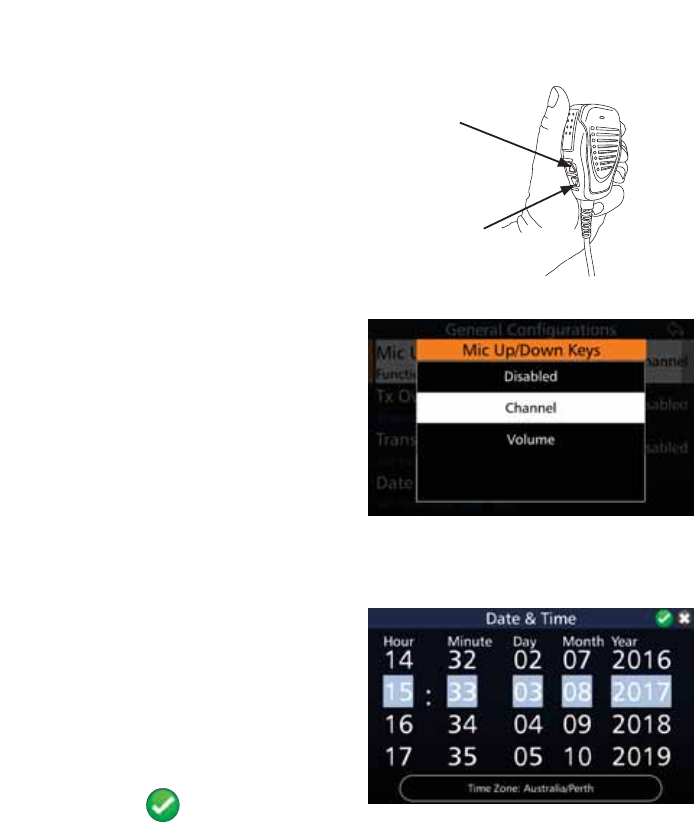
53
BARRETT 4050 HF SDR TRANSCEIVER - OPERATING AND INSTALLATION MANUAL
Mic Up / Down Keys
The keys on the side of the micro-
phone can be assigned to:
• Change channel (up / down)
• Change volume (up / down)
• Disabled.
Up Button
Down Button
Tap 0LF8S'RZQ.H\V from the
*HQHUDO&RQÀJXUDWLRQVVFUHHQWRGLV-
play the Mic Up/Down Keys screen.
Select either: Disabled, Channel, or
Volume.
See page 24 for information on
how to use the microphone.
Date and Time
Tap 'DWHDQG7LPH from the Gen-
HUDO&RQÀJXUDWLRQVVFUHHQWRGLVSOD\
the Date & Time screen.
Set the Transceiver’s date and time
by swiping the touch screen vertically
against the columns for hour, min-
ute, day, month, and year.
:KHQWKHKLJKOLJKWHGÀJXUHVDUH
correct, tap to save.
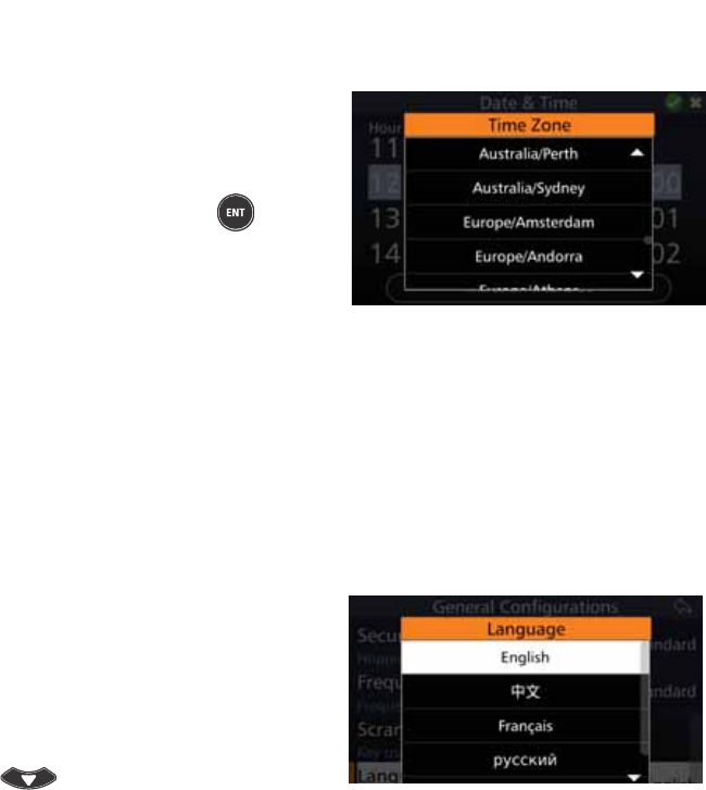
54
BARRETT 4050 HF SDR TRANSCEIVER - OPERATING AND INSTALLATION MANUAL
Time Zone
Tap Time Zone from the Date &
Time screen to display the Time Zone
screen.
Scroll up or down to reveal more
time zones. Tap or press to select
a desired time zone. The dates and
times will automatically populate the
ÀHOGVLQWKH'DWHDQG7LPHVFUHHQ
BITE Test
Tap BITE Test to perform internal testing. These tests essentially include all the
hardware which make up the Transceiver.
The built in test is also automatically performed when the Transceiver is
switched on.
Language
Tap Language from the General
&RQÀJXUDWLRQVVFUHHQWRGLVSOD\WKH
Language screen.
Change the display language from
the list shown.
To reveal more languages, swipe
down on the touch screen or press
.
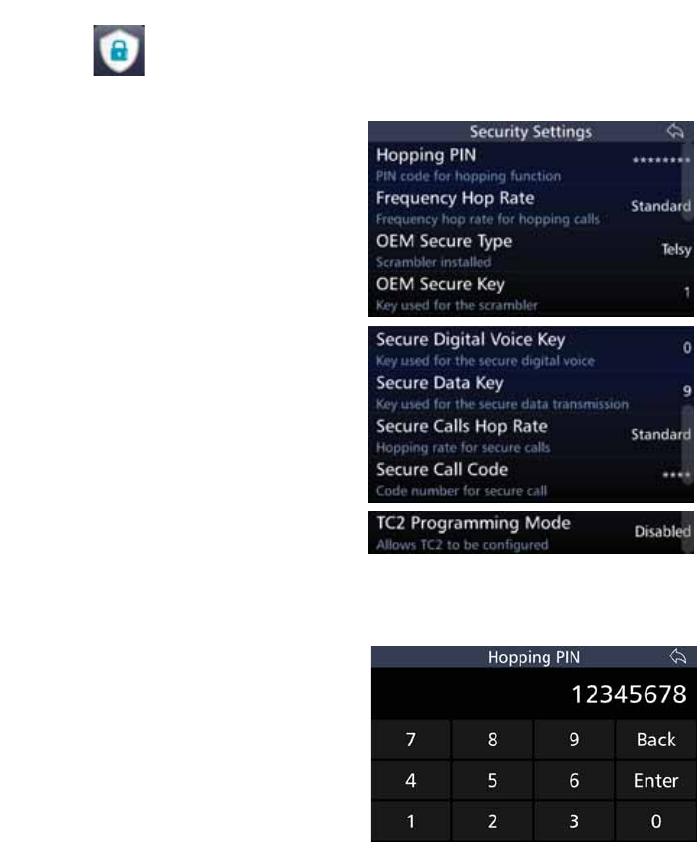
55
BARRETT 4050 HF SDR TRANSCEIVER - OPERATING AND INSTALLATION MANUAL
Security
7KLVVHFWLRQLVXVHGWRFRQÀJXUHWKHVHFXULW\VHWWLQJVIRUWKH7UDQVFHLYHU
Tap 6HFXULW\ from the General
&RQÀJXUDWLRQVVFUHHQWRGLVSOD\WKH
Security Settings screen.
$OLVWRILWHPVWKDWPD\EHFRQÀJ-
ured is displayed.
A brief description of each of the
items is described beneath the items.
The current status of each of the
items is displayed to the right.
Each item is described below.
Hopping PIN
Tap +RSSLQJ3,1 from the Security
Settings screen to display the Hop-
ping PIN screen.
Type the Hopping PIN (maximum 8
characters) and then tap Enter.
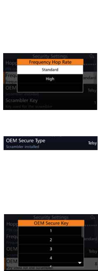
56
BARRETT 4050 HF SDR TRANSCEIVER - OPERATING AND INSTALLATION MANUAL
Frequency Hop Rate
Frequency hopping can be used to limit performance degradation due to
interference and to reduce the likelihood of interception. Frequency Hopping
Spread Spectrum (FHSS) is a method of transmitting radio signals by rapidly
switching a carrier among many frequency channels.
The Frequency Hop Rate is the rate at
which the frequency hopping moves
between transmission frequencies.
Tap )UHTXHQF\+RS5DWH from the
Security Settings screen to display
the Frequency Hop Rate screen.
Select either Standard or High.
OEM Secure Type
This displays whether a scrambler
has been installed and the name of
the scrambler. See below for further
information.
OEM Secure Key
The Audio Scrambler option is only available to Transceivers using the internally
ÀWWHGDXGLRVFUDPEOHUDFFHVVRU\PRGXOHWKDWSURYLGHVEDFNZDUGVFRPSDWLELOLW\
to the 900 series audio inversion scrambler (P/N BCA20031), Telsy, or the Tran-
scrypt scrambler. This option uses the OEM Scrambler encryption.
Tap 2(06HFXUH.H\ from the
Security Settings screen to display the
OEM Secure Key screen.
Select between 1 and 16 for the Tran-
scrypt scrambler or 1 and 32 for the
audio inversion scrambler.
All stations using an Audio Scrambler
require the same scrambler code to
be entered in order to communicate.
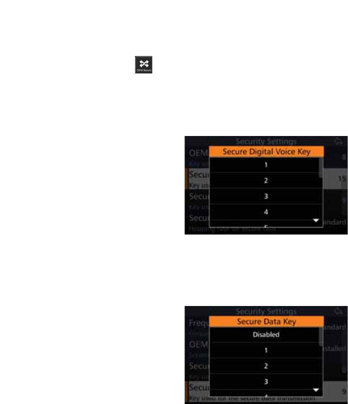
57
BARRETT 4050 HF SDR TRANSCEIVER - OPERATING AND INSTALLATION MANUAL
1RWH,IXVLQJWKHLQWHUQDOO\ÀWWHGUROOLQJFRGHDXGLRVFUDPEOHUDFFHVVRU\PRGXOH
the code must be set on the unit before installation using an external programmer.
To enable the scrambler, access the Swipe menu by swiping the home screen
from left to right, then tap .
For more information, refer to the Swipe Menu on page 138.
Secure Digital Voice Key
The Secure Digital Voice Key is used
for secure digital voice. Keys need to
EHHQWHUHGLQWRWKH7&PRGXOHÀUVW
using a third party TC2 tool.
Tap 6HFXUH'LJLWDO9RLFH.H\ from
the Security Settings screen to display
the Secure Digital Voice Key screen.
Select between 1 and 15.
The Transmit Transceiver must have
the same number key as the Receive
Transceiver in order to communicate.
Secure Data Key
The Secure Data Key is used to secure
data. Keys need to be entered into
WKH7&PRGXOHÀUVWXVLQJDWKLUG
party TC2 tool.
Tap 6HFXUH'DWD.H\ from the Se-
curity Settings screen to display the
Secure Data Key screen.
Select either Disabled or a value
between 1 and 15.
The Transmit Transceiver must have
the same number key as the Receive
Transceiver in order to communicate.
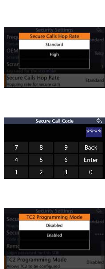
58
BARRETT 4050 HF SDR TRANSCEIVER - OPERATING AND INSTALLATION MANUAL
Secure Calls Hop Rate
The Secure Calls Hop Rate is the rate
at which the secure call hopping
moves between transmission fre-
quencies. Unlike frequency hopping,
it doesn’t utilise GPS.
Tap 6HFXUH&DOOV+RS5DWH from
the Security Settings screen to display
the Secure Calls Hop Rate screen.
Select either Standard or High.
Secure Call Code
Tap 6HFXUH&DOO&RGH from the
Security Settings screen to display the
Secure Call Code screen.
Type the four digit PIN and tap
Enter.
TC2 Programming Mode
,IWKH7UDQVFHLYHULVÀWWHGZLWKD7&
module, this option enables TC2 to
be programmed.
Tap TC2 Programming Mode from
the Security Settings screen to display
the TC2 Programming Mode screen.
Select either Disabled or Enabled.
When enabled, the functionality
of the Transceiver is disabled. After
programming the TC2, reboot the
Transceiver.
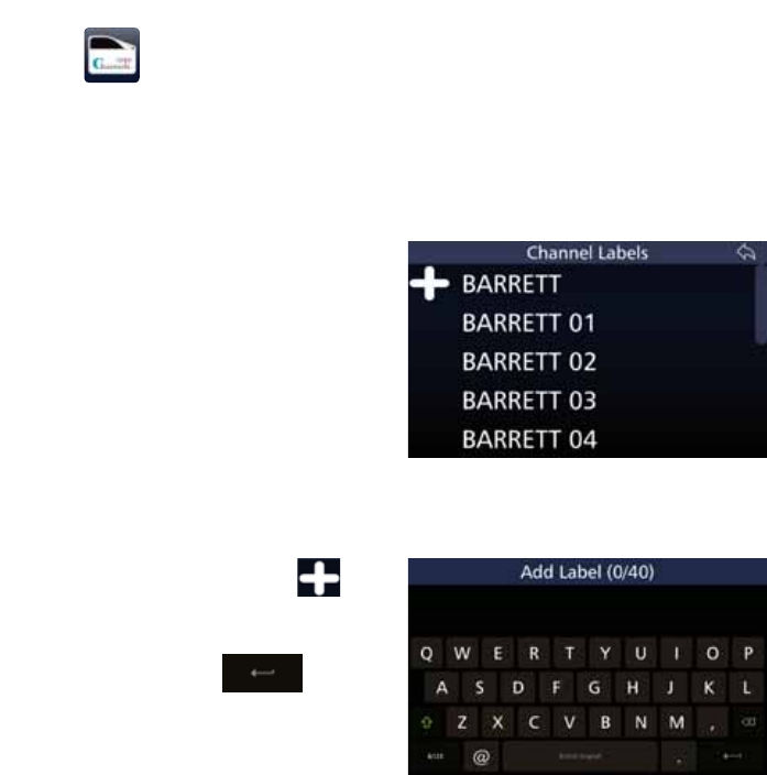
59
BARRETT 4050 HF SDR TRANSCEIVER - OPERATING AND INSTALLATION MANUAL
Labels
This section describes how to add, edit, or erase channel labels. Channel labels
are used to indicate what a particular channel is used for. For example, UNHCR
Geneva.
Note: Channel labels may be applied to channels when adding a channel.
See page 62.
Tap Labels from the Settings screen
to display the Channel Labels screen.
A list of currently used channel labels
display.
Add a Channel Label
To add a channel label, tap to
display the Add Label screen.
Use the keyboard to type the name of
the label, then tap
yp
to save.
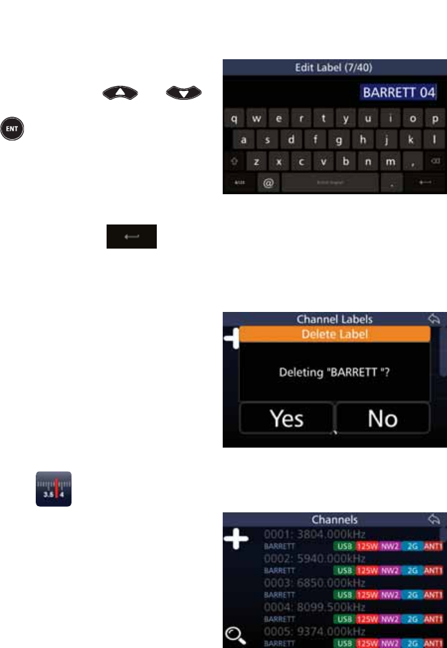
60
BARRETT 4050 HF SDR TRANSCEIVER - OPERATING AND INSTALLATION MANUAL
Edit a Channel Label
To edit a channel label from the
Channel Labels’ screen, select the
label by using the and
keys and either tap the label or press
from the keypad.
The Edit Label screen displays. The
numbers in the parenthesis indicate
how many characters you have used /
total number of characters allowed.
Use the keyboard to edit the name of
the label, then tap to save.
Delete a Channel Label
To delete a channel label from the
Channel Labels’ screen, select the
channel label you wish to delete,
then tap and hold for three seconds.
$FRQÀUPDWLRQPHVVDJHGLVSOD\V
Tap Yes.
Channels
Tap Channels from the Settings
screen to display the Channels screen.
A list of currently used channel dis-
plays. Each channel shows its channel
number, frequency, and channel
label.
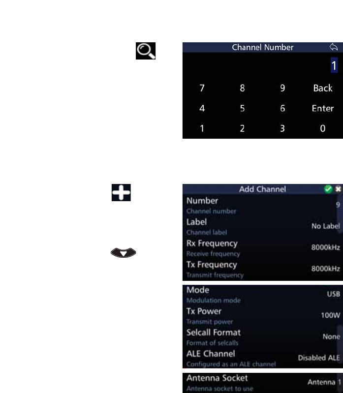
61
BARRETT 4050 HF SDR TRANSCEIVER - OPERATING AND INSTALLATION MANUAL
Search For a Channel
To search for a channel, tap to
display the Channel Number screen.
Tap the appropriate digits for the
search, then tap Enter.
Add a Channel
To add a channel, tap to display
the Add Channel screen.
A list of attributes that may be con-
ÀJXUHGLVGLVSOD\HG7RUHYHDOPRUH
attributes, either swipe down on the
touch screen or press .
A brief description of each of the
DWWULEXWHVZKLFKPD\EHFRQÀJXUHGLV
described beneath the attribute.
The current status of each of the
attributes is displayed to the right.
Each attribute on the list is described
below.
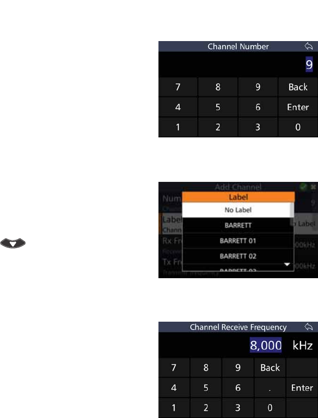
62
BARRETT 4050 HF SDR TRANSCEIVER - OPERATING AND INSTALLATION MANUAL
Number
Tap 1XPEHU from the Add Channel
screen to display the Channel Num-
ber screen.
The default shows the next available
channel number.
Tap %DFNWRFOHDUWKH(QWU\ÀHOG7DS
the appropriate digits to represent
the desired channel number, then tap
Enter.
Label
Tap Label from the Add Channel
screen to display the Label screen.
Select a label from the Label screen.
To reveal more items, either swipe
down on the touch screen or press
.
See page 59 for information on
Channel labels.
Rx Frequency
Tap 5[)UHTXHQF\ from the Add
Channel screen to display the Chan-
nel Receive Frequency screen.
Tap %DFNWRFOHDUWKH(QWU\ÀHOG
Tap the digits to represent the desired
values (in kHz).
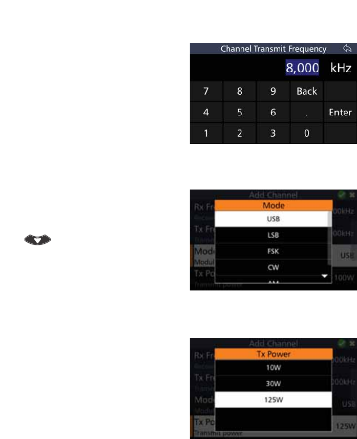
63
BARRETT 4050 HF SDR TRANSCEIVER - OPERATING AND INSTALLATION MANUAL
Tx Frequency
Tap 7[)UHTXHQF\ from the Add
Channel screen to display the Chan-
nel Transmit Frequency screen.
Tap %DFNWRFOHDUWKH(QWU\ÀHOG
Tap the digits to represent the desired
values (in kHz).
Mode
Tap Mode from the Add Channel
screen to display the Mode screen.
To reveal more items, either swipe
down on the touch screen or press
.
The choices are: Upper Sideband,
Lower Sideband, Frequency Shift Key-
ing, Continuous Wave (Morse code),
and Amplitude Modulation.
Tx Power
Tap Tx Power from the Add Channel
screen to display the Tx Power screen.
Select either: 10 W, 30 W, or 125 W.
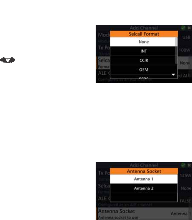
64
BARRETT 4050 HF SDR TRANSCEIVER - OPERATING AND INSTALLATION MANUAL
Selcall Format
Tap 6HOFDOO)RUPDW from the Add
Channel screen to display the Selcall
Format screen.
To reveal more items, either swipe
down on the touch screen or press
.
Select either: None, INT, CCIR, OEM,
RFDS, NW1, NW2, NW3, NW4, or
NW5.
Refer to page 28 for further infor-
mation on Selcall systems.
ALE Channel
Displays the ALE status of a channel:
either: True, False, or Disabled.
Antenna Socket
Tap $QWHQQD6RFNHW from the Add
Channel screen to display the Anten-
na Socket screen.
Select either: Antenna 1 or
Antenna 2.
Note: As there is only one antenna
socket on the Transceiver, this option
only applies if you are using a Break out
box.
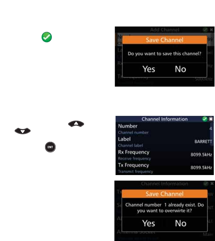
65
BARRETT 4050 HF SDR TRANSCEIVER - OPERATING AND INSTALLATION MANUAL
Save Channel
$IWHUFRQÀJXULQJWKHDERYHDWWUL-
butes, tap to add the channel.
$FRQÀUPDWLRQPHVVDJHGLVSOD\V
Tap Yes.
Edit a Channel
To edit a channel, select the desired
channel by using the and
keys from the Channel screen
(page 60) and either tap the chan-
nel or press from the keypad.
The Channel Information screen
GLVSOD\V(GLWWKHÀHOGVDVGHVFULEHG
above (Add a Channel).
After the channel’s attributes have
EHHQHGLWHGDFRQÀUPDWLRQPHVVDJH
displays.
Tap Yes.
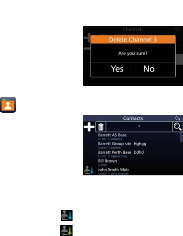
66
BARRETT 4050 HF SDR TRANSCEIVER - OPERATING AND INSTALLATION MANUAL
Delete a Channel
To delete a channel, tap and hold for
three seconds the channel you wish
WRGHOHWH$FRQÀUPDWLRQPHVVDJH
displays.
Tap Yes.
Contacts
Tap &RQWDFWV from the Settings
screen to display the Contacts screen.
A list of contacts display. Each
contact shows their Selcall ID and
telephone number.
Sort Contacts
There are two sort icons.
• 7RVRUWE\ÀUVWQDPHWDS .
• To sort by last name, tap .
Only one sort icon will display at any time.
,IWKHOLVWKDVDOUHDG\EHHQVRUWHGE\ÀUVWQDPHWKH6RUW%\/DVW1DPHLFRQZLOO
display.
If the list has already been sorted by last name, the Sort By First Name icon will
display.
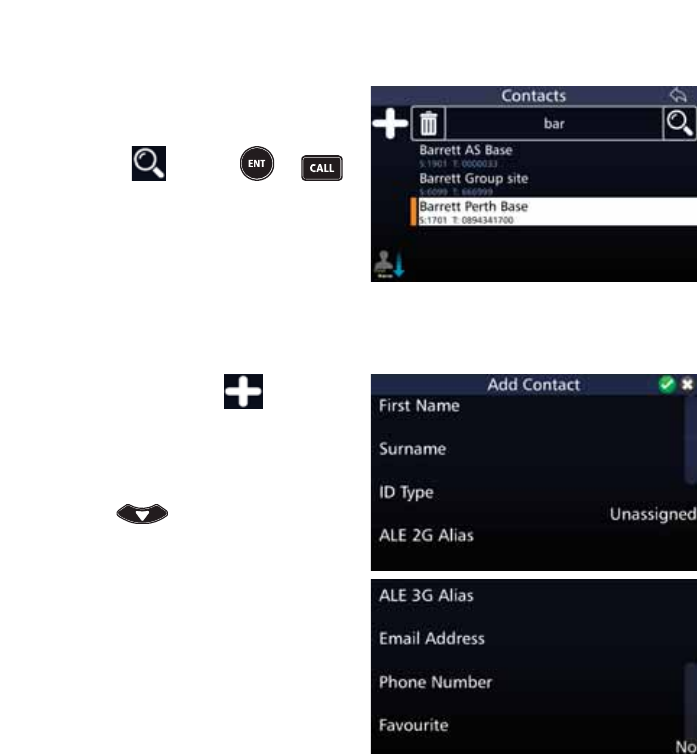
67
BARRETT 4050 HF SDR TRANSCEIVER - OPERATING AND INSTALLATION MANUAL
Search Contacts
To search contacts, tap the Contacts
ÀHOGWRUHYHDODNH\ERDUG7DSWKH
VHDUFKFULWHULDLQWRWKH&RQWDFWVÀHOG
Either tap or press or
to display the results of the search.
Add a Contact
To add a contact, tap The Add
Contact screen displays.
$OLVWRILWHPVWKDWPD\EHFRQÀJXUHG
is displayed. To reveal more items, ei-
ther swipe down on the touch screen
or press .
The current status of each of the
items is displayed to the right.
Each item on the list is described
below.
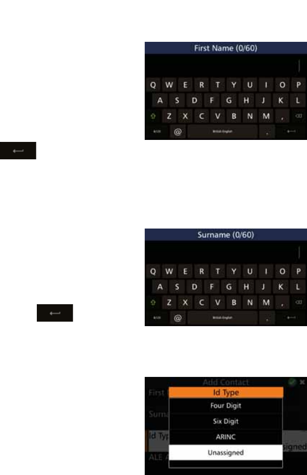
68
BARRETT 4050 HF SDR TRANSCEIVER - OPERATING AND INSTALLATION MANUAL
First Name
Tap )LUVW1DPH from the Add Con-
tact screen to display the First Name
screen.
Tap the appropriate characters from
the keyboard into the First Name
ÀHOG7KHQXPEHUVLQWKHSDUHQWKHVLV
indicate how many characters you
have used / total number of charac-
ters allowed.
Tap to save and return to
the Add Contact screen.
Surname
Tap Surname from the Add Contact
screen to display the Surname screen.
Tap the appropriate characters from
WKHNH\ERDUGLQWRWKH6XUQDPHÀHOG
The numbers in the parenthesis indi-
cate how many characters you have
used / total number of characters
allowed. Tap to save and
return to the Add Contact screen.
ID Type
Tap ,'7\SH from the Add Contact
screen to display the ID Type screen.
Select either: Four digit, six digit, or
ARINC. These options are described
below.
Select Unassigned if there is no Id
type to be associated with the con-
tact.
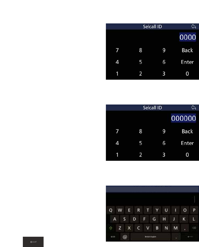
69
BARRETT 4050 HF SDR TRANSCEIVER - OPERATING AND INSTALLATION MANUAL
Four Digit
Tap )RXU'LJLW from the Id Type
screen to display the Selcall ID screen.
Tap the appropriate characters from
WKHNH\ERDUGLQWRWKH6HOFDOO,'ÀHOG
Tap Enter to save and return to the
Add Contact screen.
Six Digit
Tap 6L['LJLW from the Id Type screen
to display the Selcall ID screen.
Tap the appropriate characters from
WKHNH\ERDUGLQWRWKH6HOFDOO,'ÀHOG
Tap Enter to save and return to the
Add Contact screen.
ARINC
Tap $5,1& from the Id Type screen to
display the ARINC Call screen.
Tap the appropriate characters from
the keyboard into the ARINC Call
ÀHOG7KHQXPEHUVLQWKHSDUHQWKHVLV
indicate how many characters you
have used / total number of charac-
ters allowed.
Tap to save and return to
the Add Contact screen.
ARINC Call (0/4)
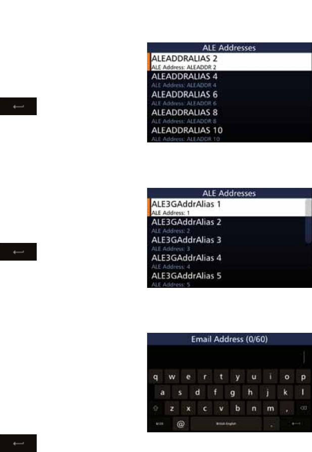
70
BARRETT 4050 HF SDR TRANSCEIVER - OPERATING AND INSTALLATION MANUAL
ALE 2G Alias
Tap ALE 2G Alias from the Add
Contact screen to display the ALE
Addresses screen. Tap the appropriate
characters from the keyboard into
WKH$/($GGUHVV,'ÀHOG
Tap to save and return to
the Add Contact screen.
ALE 3G Alias
Tap ALE 3G Alias from the Add
Contact screen to display the ALE
Addresses screen. Tap the appropriate
characters from the keyboard into
WKH$/($GGUHVV,'ÀHOG
Tap to save and return to
the Add Contact screen.
Email Address
Tap Email Address from the Add
Contact screen to display the Email
Address screen.
Tap the appropriate characters from
the keyboard into the Email Address
ÀHOG7KHQXPEHUVLQWKHSDUHQWKHVLV
indicate how many characters you
have used / total number of charac-
ters allowed.
Tap to save and return to
the Add Contact screen.
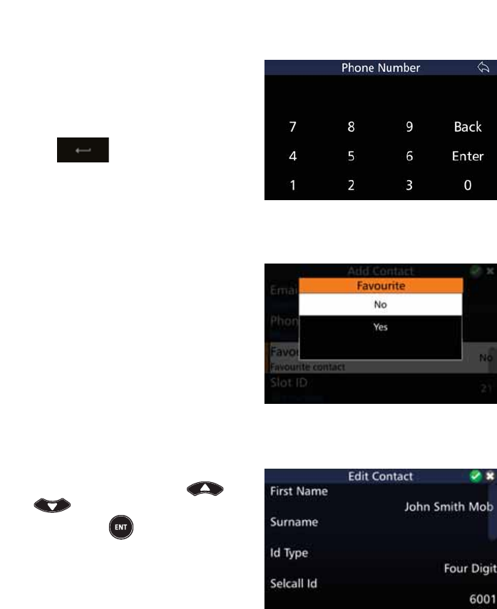
71
BARRETT 4050 HF SDR TRANSCEIVER - OPERATING AND INSTALLATION MANUAL
Phone Number
Tap 3KRQH1XPEHU from the Add
Contact screen to display the Phone
Number screen. Tap the appropriate
characters from the keyboard into
WKH3KRQH1XPEHUÀHOG
Tap to save and return to
the Add Contact screen.
Favourite
Tap )DYRXULWH from the Add Con-
tact screen to display the Favourite
screen.
Select Yes to add to the favourite
contacts.
Edit Contact
To edit contact details, select the de-
sired contact by using the and
keys and either tap the con-
tact or press from the keypad
The Edit Contact screen displays. Edit
the details as described above (for
Add Contact).
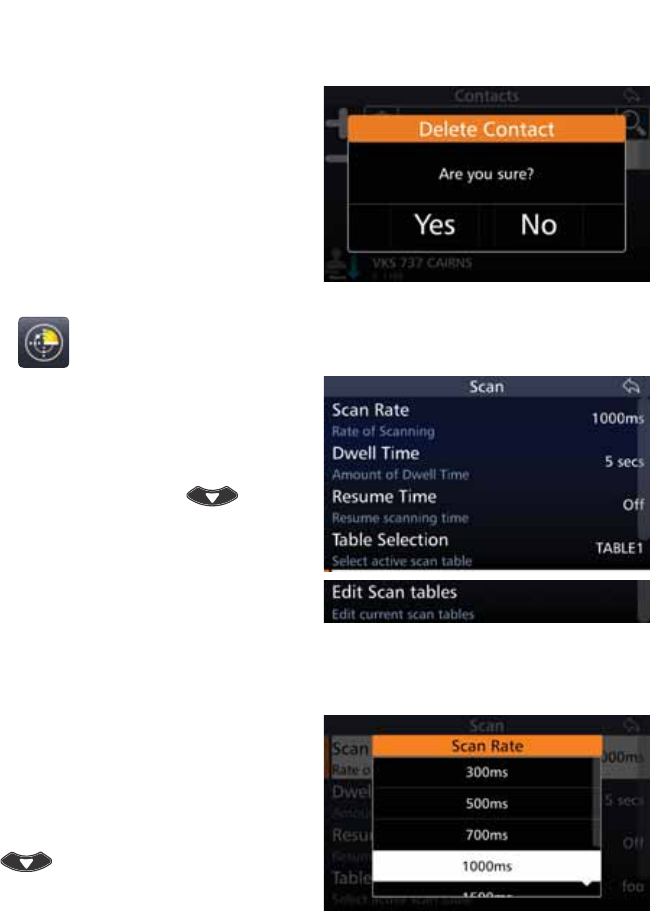
72
BARRETT 4050 HF SDR TRANSCEIVER - OPERATING AND INSTALLATION MANUAL
Delete Contact
Select the contact to be deleted, then
tap and hold for three seconds.
$FRQÀUPDWLRQPHVVDJHGLVSOD\V
Tap Yes.
Scan
Tap 6FDQ from the Settings screen
to display the Scan screen.
$OLVWRILWHPVWKDWPD\EHFRQÀJ-
ured is displayed. To reveal more
items, either swipe down on the
touch screen or press .
Each item is described below.
Scan Rate
Select the scan rate applicable to
non-Selcall scan channels.
Tap 6FDQ5DWH from the Scan screen
to display the Scan Rate screen.
To reveal more items, either swipe
down on the touch screen or press
.
Select either: 300, 500, 700, 1000,
1500, 2000, or 5000 ms.
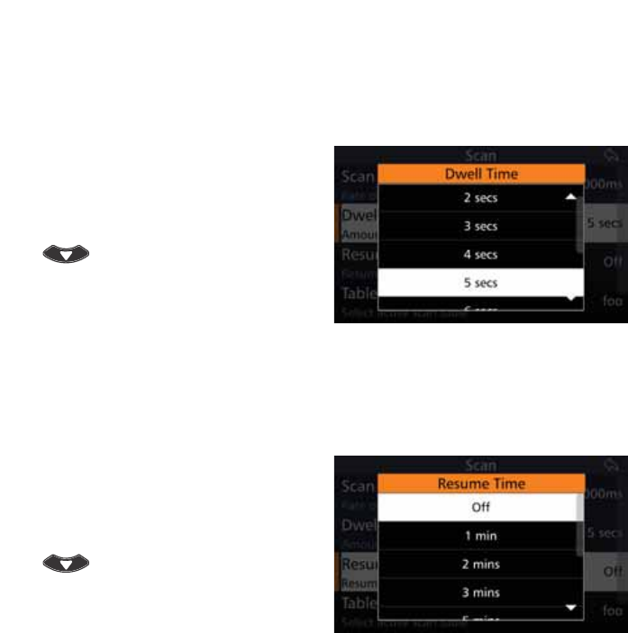
73
BARRETT 4050 HF SDR TRANSCEIVER - OPERATING AND INSTALLATION MANUAL
Dwell Time
Select the length of time the Transceiver dwells (waits) on a channel after scan
has been stopped by signal strength level (if signal strength level mute is set) or
voice activity (if audio mute is set).
Tap 'ZHOO7LPH from the Scan
screen to display the Dwell Time
screen.
To reveal more items, either swipe
down on the touch screen or press
.
Select between one and ten seconds.
Resume Time
Set the time period after which the Transceiver will automatically resume scan-
ning from the last operation. For example, after a key press or PTT.
Tap Resume Time from the Scan
screen to display the Resume Time
screen.
To reveal more items, either swipe
down on the touch screen or press
.
Select either: Off, 1, 2, 3, 5, 10, 15,
20, or 30 minutes.
Table Selection
Select the Scan Table to be used when the Transceiver is put into scan mode, or
if enabled, when scan resume occurs.
There can be up to eight Scan Tables.
Note: When scrolling through the Scan Tables to make a selection, only Scan Tables
with channels entered will display. If none of the Scan tables have any channel
entries, the message “All Scan Tables Empty“ displays.
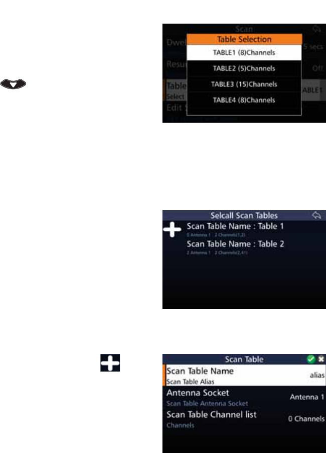
74
BARRETT 4050 HF SDR TRANSCEIVER - OPERATING AND INSTALLATION MANUAL
Tap 7DEOH6HOHFWLRQ from the Scan
screen to display the Table Selection
screen.
To reveal more items, either swipe
down on the touch screen or press
.
The example shows four tables to
select from. Each table revealing the
name of the table and the respective
number of channels.
Edit Scan Tables
Note: All channels are displayed in numerical order within the scan table with
respect to the entry number. There are a maximum of 30 entries in each table.
Tap (GLW6FDQ7DEOHV from the Scan
screen to display the Selcall Scan
Tables screen.
The example shows two scan tables
which may be edited. Each table
reveals the name of the table, the
antenna, the number of channels in
the table and the channel numbers.
Add a Scan Table
To add a Scan Table, tap . The
Scan Table screen displays.
$OLVWRILWHPVWKDWPD\EHFRQÀJXUHG
is displayed.
A brief description of each of the
LWHPVZKLFKPD\EHFRQÀJXUHGLV
described beneath the items.
The current status of each of the
items is displayed to the right.
Each item on the list is described
below.
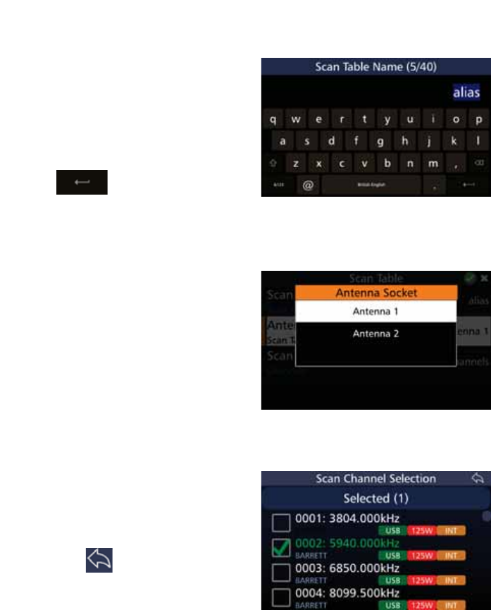
75
BARRETT 4050 HF SDR TRANSCEIVER - OPERATING AND INSTALLATION MANUAL
Scan Table Name
Tap 6FDQ7DEOH1DPH from the Scan
Table screen to display the Scan Table
Name screen.
The default name is alias. Overtype
the default name by tapping the
appropriate characters from the key-
ERDUGLQWRWKH6FDQ7DEOH1DPHÀHOG
Tap to save and return to
the Scan Table screen.
Antenna Socket
Tap $QWHQQD6RFNHW from the Scan
Table screen to display the Antenna
Socket screen.
Select either Antenna 1 or Antenna 2.
Note: As there is only one antenna
socket on the Transceiver, this option
only applies if you are using a Break out
box.
Scan Table Channel List
Tap 6FDQ7DEOH&KDQQHO List from
the Scan Table screen to display the
Scan Channel Selection screen.
Tap the checkboxes adjacent to the
channels you wish to choose and
then tap
y
.
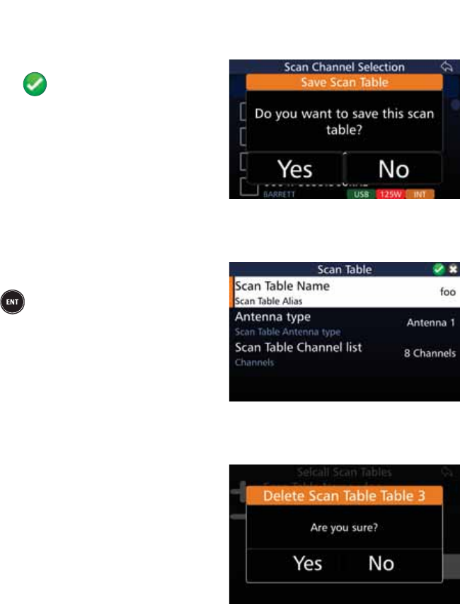
76
BARRETT 4050 HF SDR TRANSCEIVER - OPERATING AND INSTALLATION MANUAL
Save a Scan Table
$IWHUFRQÀJXULQJWKHDERYHLWHPV
tap to add the table.
$FRQÀUPDWLRQPHVVDJHGLVSOD\V
Tap Yes.
Edit a Scan Table
To edit a table, select the desired
table and either tap the table or press
from the keypad.
The Scan Table screen displays. Edit
the details as described above (for
Add a Scan Table).
Delete a Scan Table
Select the table to be deleted, then
tap and hold for three seconds.
$FRQÀUPDWLRQPHVVDJHGLVSOD\V
Tap Yes.
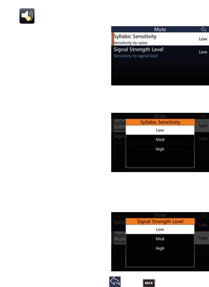
77
BARRETT 4050 HF SDR TRANSCEIVER - OPERATING AND INSTALLATION MANUAL
Mute
Tap Mute from the Settings screen to
display the Mute screen.
$OLVWRILWHPVWKDWPD\EHFRQÀJXUHG
is displayed.
Each item is described below.
Syllabic Sensitivity
Set the sensitivity or ‘hardness’ of the
syllabic mute (squelch).
Tap 6\OODELF6HQVLWLYLW\ from the
Mute screen to display the Syllabic
Sensitivity screen.
Select either: Low, Medium, or High
sensitivity to voice activity on a
channel.
Signal Strength Level
Select the level at which the Signal Strength Level (SSL) mute (squelch) opens.
Tap 6LJQDO6WUHQJWK/HYHO from
the Mute screen to display the Signal
Strength Level screen.
Select either: Low, Medium, or High.
When set to low, the mute will open
on a relatively low level of received
signal. When set to high, the mute
will open on a relatively high level of
received signal.
$IWHUFRQÀJXULQJWKHDERYHLWHPVWDS or press to save the settings
and return to the Mute screen.
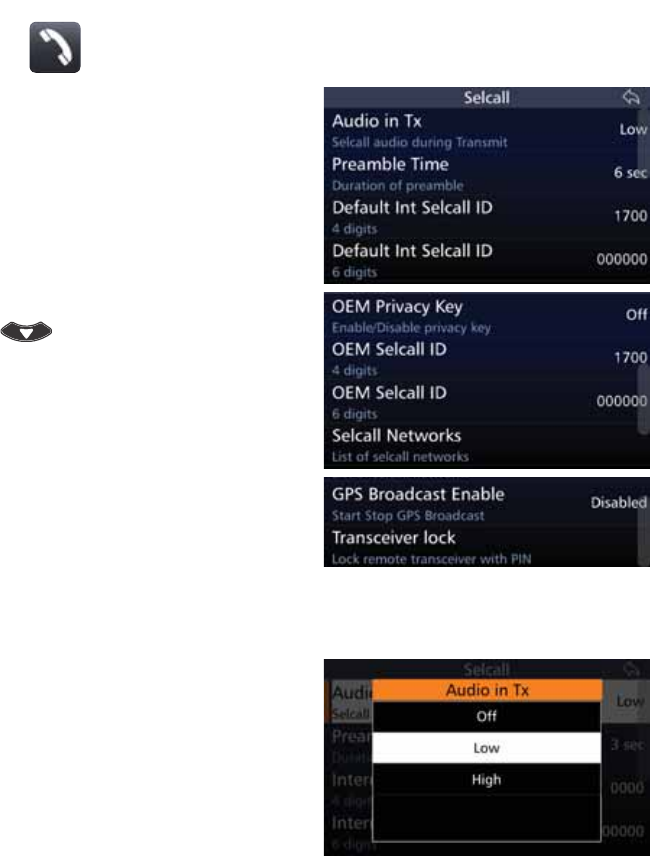
78
BARRETT 4050 HF SDR TRANSCEIVER - OPERATING AND INSTALLATION MANUAL
Selcall
Tap 6HOFDOO from the Settings screen
to display the Selcall screen.
$OLVWRILWHPVWKDWPD\EHFRQÀJXUHG
is displayed.
A brief description of each of the
items is described beneath the items.
The current status of each of the
items is displayed to the right.
To reveal more items, either swipe
down on the touch screen or press
.
Each item is described below.
Audio in Tx
Tap Audio in Tx from the Selcall
screen to display the Audio in Tx
screen.
Select either: Off, Low, or High.
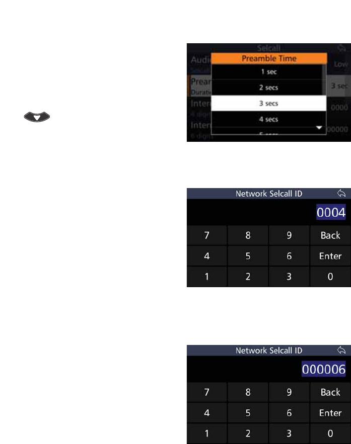
79
BARRETT 4050 HF SDR TRANSCEIVER - OPERATING AND INSTALLATION MANUAL
Preamable Time
Tap Preamble Time from the Selcall
screen to display the Preamble Time
screen.
Select between one and ten seconds.
To reveal more items, either swipe
down on the touch screen or press
.
Default Int Selcall ID (4 Digits)
Tap 'HIDXOW,QW6HOFDOO,' from the
Selcall screen to display the Network
Selcall ID screen.
The default in this example is four
digits 0000. Overtype the default by
tapping the appropriate characters
from the keyboard into the Network
6HOFDOO,'ÀHOG
Tap Enter to save and return to the
Selcall screen.
Default Int Selcall ID (6 Digits)
Tap 'HIDXOW,QW6HOFDOO,' from the
Selcall screen to display the Network
Selcall ID screen.
The default in this example is six dig-
its 000000. Overtype the default by
tapping the appropriate characters
from the keyboard into the Network
6HOFDOO,'ÀHOG
Tap Enter to save and return to the
Selcall screen.
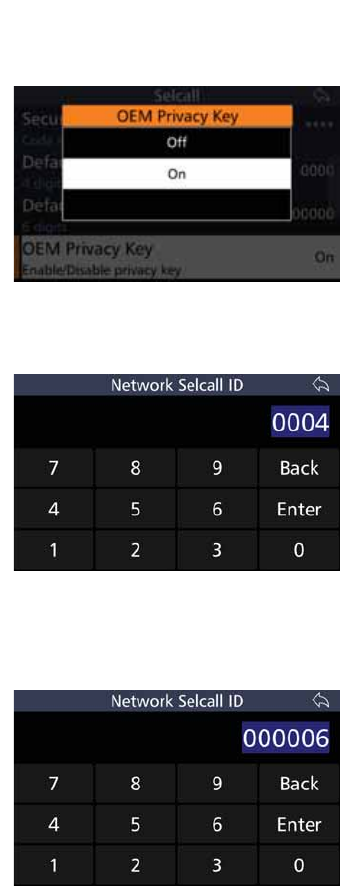
80
BARRETT 4050 HF SDR TRANSCEIVER - OPERATING AND INSTALLATION MANUAL
OEM Privacy Key
Tap 2(03ULYDF\.H\ from the
Selcall screen to display the OEM
Privacy Key screen.
Select either On or Off.
OEM Selcall ID (4 Digits)
Tap 2(06HOFDOO,' from the Selcall
screen to display the Network Selcall
ID screen.
The default in this example is six
digits 0000. Overtype the default by
tapping the appropriate characters
from the keyboard into the Network
6HOFDOO,'ÀHOG
Tap Enter to save and return to the
Selcall screen.
OEM Selcall ID (6 Digits)
Tap 2(06HOFDOO,' from the Selcall
screen to display the Network Selcall
ID screen.
The default in this example is six dig-
its 000000. Overtype the default by
tapping the appropriate characters
from the keyboard into the Network
6HOFDOO,'ÀHOG
Tap Enter to save and return to the
Selcall screen.
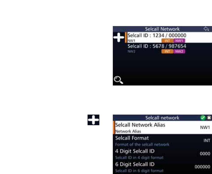
81
BARRETT 4050 HF SDR TRANSCEIVER - OPERATING AND INSTALLATION MANUAL
Selcall Networks
Tap 6HOFDOO1HWZRUNV from the
Selcall screen to display the Selcall
Network screen.
The example shows two Selcall Net-
ZRUNVPD[LPXPÀYHZKLFKPD\EH
edited. Each Selcall Network reveal-
ing the name of the network alias,
the Selcall format, the four and six
digit Selcall ID.
Add a Selcall Network
To add a Selcall Network, tap .
The Selcall Network screen displays.
$OLVWRILWHPVWKDWPD\EHFRQÀJXUHG
is displayed.
A brief description of each of the
items is described beneath the items.
The current status of each of the
items is displayed to the right.
Each item on the list is described
below.
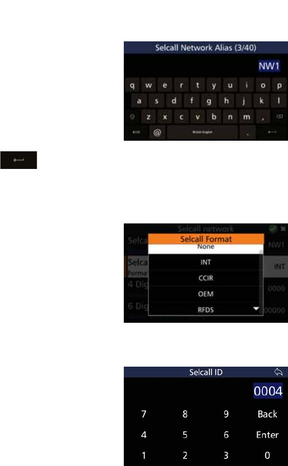
82
BARRETT 4050 HF SDR TRANSCEIVER - OPERATING AND INSTALLATION MANUAL
Selcall Network Alias
Tap 6HOFDOO1HWZRUN$OLDV from
the Selcall Network screen to display
the Selcall Network Alias screen. The
numbers in the parenthesis indicate
how many characters you have used /
total number of characters allowed.
The default alias is NW1. Overtype
the default alias by tapping the
appropriate characters from the key-
board into the Selcall Network Alias
ÀHOG7DS to save and return
to the Selcall Network screen.
Selcall Format
Tap 6HOFDOO)RUPDW from the Selcall
Network screen to display the Selcall
Format screen.
Select either: None, INT, CCIR, OEM,
or RFDS.
4 Digit Selcall ID
Tap 'LJLW6HOFDOO,' from the
Selcall Network screen to display the
Selcall ID screen.
The default ID is 0000. Overtype the
default ID by tapping the appropriate
characters from the keyboard into
WKH6HOFDOO,'ÀHOG
Tap Enter to save and return to the
Selcall Network screen.
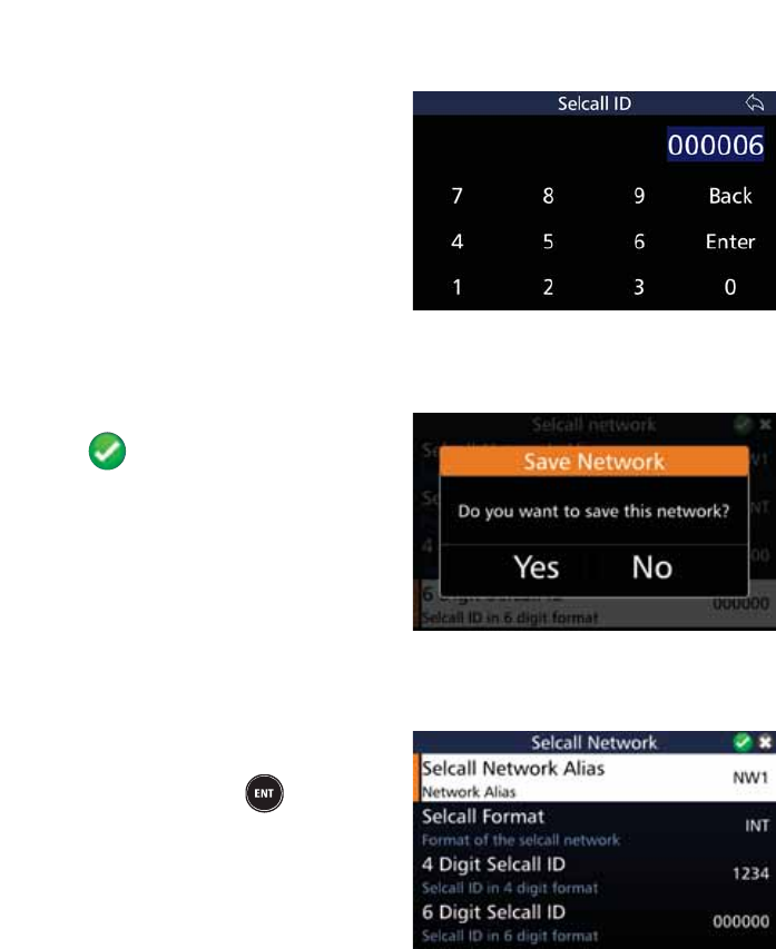
83
BARRETT 4050 HF SDR TRANSCEIVER - OPERATING AND INSTALLATION MANUAL
6 Digit Selcall ID
Tap 'LJLW6HOFDOO,' from the
Selcall Network screen to display the
Selcall ID screen.
The default ID is 000000. Overtype
the default ID by tapping the appro-
priate characters from the keyboard
LQWRWKH6HOFDOO,'ÀHOG
Tap Enter to save and return to the
Selcall Network screen.
Save a Selcall Network
$IWHUFRQÀJXULQJWKHDERYHLWHPV
tap to add the Selcall Network.
$FRQÀUPDWLRQPHVVDJHGLVSOD\V
Tap Yes.
Edit a Selcall Network
To edit a Selcall Network, select
the desired network and either tap
the network or press from the
keypad.
The Selcall Network screen displays.
Edit the details as described above
(for Add a Selcall Network).
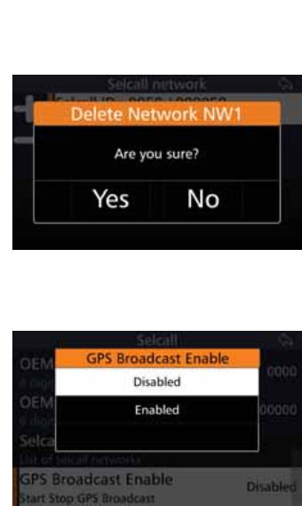
84
BARRETT 4050 HF SDR TRANSCEIVER - OPERATING AND INSTALLATION MANUAL
Delete a Selcall Network
Select the Selcall Network to be
deleted, then tap and hold for three
seconds.
$FRQÀUPDWLRQPHVVDJHGLVSOD\V
Tap Yes.
GPS Broadcast Enable
Tap *36%URDGFDVW(QDEOH from
the Selcall screen to display the GPS
Broadcast Enable screen.
Select either Disabled or Enabled.
This setting will either prevent or al-
low the periodic broadcasting of the
Transceiver’s GPS position.
Timings for the GPS broadcast are set
via the Barrett 4050 HF SDR Program-
ming software (P/N BCA40001).
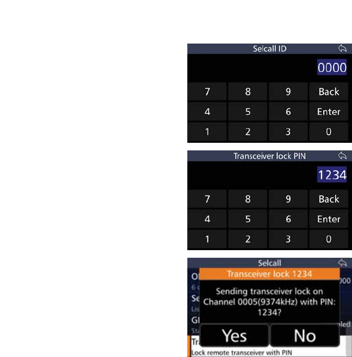
85
BARRETT 4050 HF SDR TRANSCEIVER - OPERATING AND INSTALLATION MANUAL
Transceiver Lock
To lock a remote Transceiver with a
PIN, tap 7UDQVFHLYHU/RFN from the
Selcall screen to display the Selcall ID
screen.
Use the keyboard to type the PIN,
then tap Enter.
The Transceiver Lock PIN screen
displays.
Use the keyboard to type the PIN
again, then tap Enter.
The Transceiver Lock screen displays.
Tap Yes to send a Transceiver lock on
the respective channel with the PIN.
Tap 1R to abort.
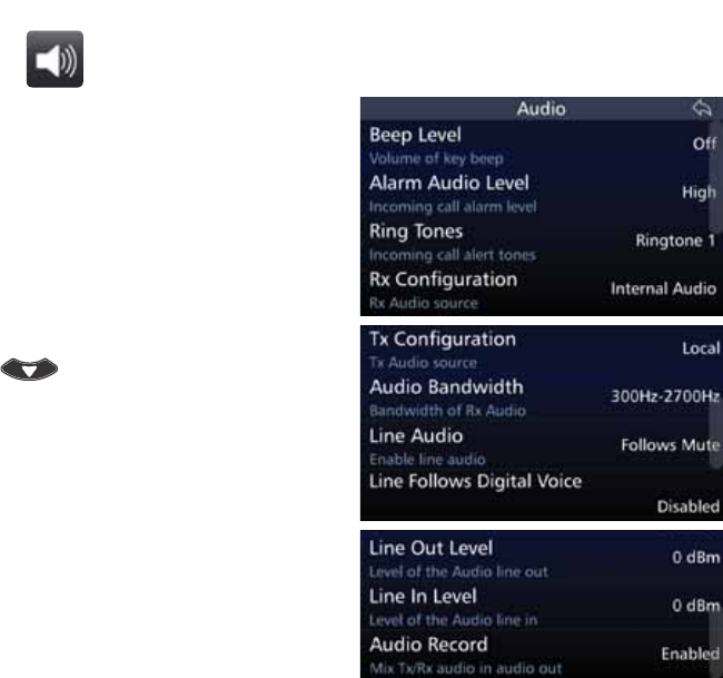
86
BARRETT 4050 HF SDR TRANSCEIVER - OPERATING AND INSTALLATION MANUAL
Audio
Tap Audio from the Settings screen
to display the Audio screen.
$OLVWRILWHPVWKDWPD\EHFRQÀJXUHG
is displayed.
A brief description of each of the
items is described beneath the items.
The current status of each of the
items is displayed to the right.
To reveal more items, either swipe
down on the touch screen or press
.
Each item is described below.
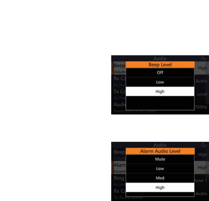
87
BARRETT 4050 HF SDR TRANSCEIVER - OPERATING AND INSTALLATION MANUAL
Beep Level
This section is used to set the annunciation beep volume levels. These are the
various tones associated with key presses. Annunciation beeps can be disabled
for covert operations. For other operations these are set purely for Operator
feedback.
Tap %HHS/HYHO from the Audio
screen to display the Beep Level
screen.
Select either: Off, Low, or High.
Alarm Audio Level
Tap $ODUP$XGLR/HYHO from the
Audio screen to display the Alarm Au-
dio Level screen.
Select either: Mute, Low, Med, or
High.
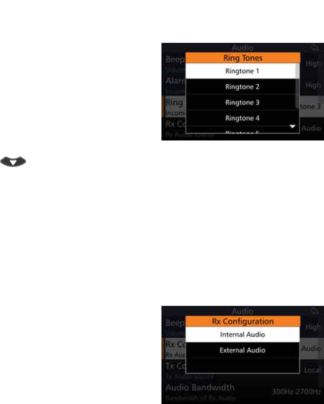
88
BARRETT 4050 HF SDR TRANSCEIVER - OPERATING AND INSTALLATION MANUAL
Ring Tones
Tap Ring Tones from the Audio
screen to display the Ring Tones
screen.
Select from a series of different
sounding tones: Ringtone 1 through
to Ringtone 7.
These ring tones are used when
receiving alarms, Selcall etc.
To reveal more items, either swipe
down on the touch screen or press
.
5[&RQÀJXUDWLRQ
This option sets where the unprocessed receiver audio in the Transceiver is
sourced.
Normally, this is set to internal in which case the Transceiver’s receiver provides
the unprocessed audio.
When used with a remote receiver in split site operations, the audio path can
be set to external. In this case, unprocessed received audio from the remote
site can be input into the auxiliary sockets 600 ohm balanced audio port.
Tap 5[&RQÀJXUDWLRQ from the Au-
GLRVFUHHQWRGLVSOD\WKH5[&RQÀJX-
ration screen.
Select either: Internal Audio, or Exter-
nal Audio.
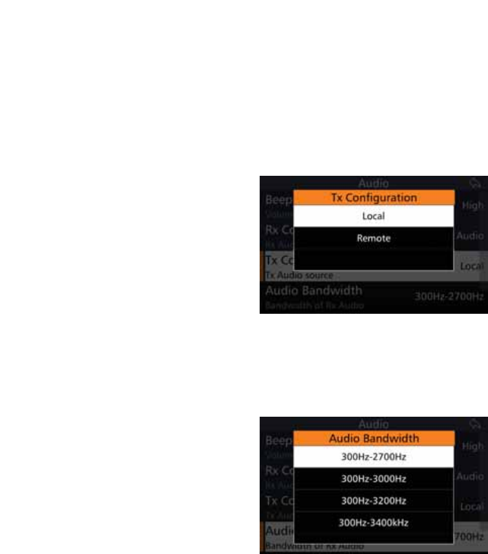
89
BARRETT 4050 HF SDR TRANSCEIVER - OPERATING AND INSTALLATION MANUAL
7[&RQÀJXUDWLRQ
This option sets where the transmitter audio in the Transceiver is sourced.
Normally, this is set to local in which case the Transceiver’s microphone pro-
vides the transmitter audio.
When used with a remote site operation, the path can be set to remote. In this
case, the transmit audio is input into the auxiliary sockets 600 ohm balanced
audio port.
Tap 7[&RQÀJXUDWLRQ from the Au-
GLRVFUHHQWRGLVSOD\WKH7[&RQÀJX-
ration screen.
Select either: Local or Remote.
Audio Bandwidth
This section allows the audio bandwidth to be tailored to an Operator’s com-
fort requirements.
Tap Audio Bandwidth from the
Audio screen to display the Audio
Bandwidth screen.
Select either:
300 Hz - 2700 Hz,
300 Hz - 3000 Hz,
300 Hz - 3200 Hz, or
300 Hz - 3400 kHz.
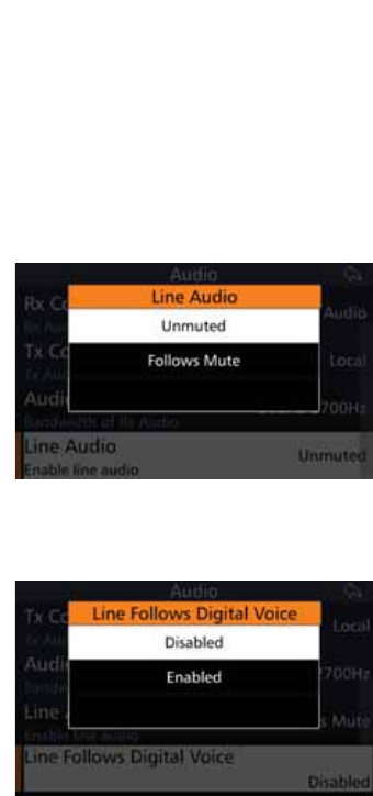
90
BARRETT 4050 HF SDR TRANSCEIVER - OPERATING AND INSTALLATION MANUAL
Line Audio
This option sets the muting condition of the 600 ohm balanced audio line out-
put on the rear auxiliary connector.
The line output can be set to Unmuted or Follows Mute. When set to Follows
Mute, the line output is muted in the same manner as the speaker output and
follows the mute condition currently in use. The line output is usually set to
Unmuted when using data modems.
Tap Line Audio from the Audio
screen to display the Line Audio
screen.
Select either: Unmuted, or Follows
Mute.
Line Follows Digital Voice
Line Follows Digital Voice may be
used for example with a 2060 Tele-
phone Interconnect. The 2060 PTTs
the radio through the line and trans-
mits the voice. From the drop-down
menu select either Off or On.
Tap /LQH)ROORZV'LJLWDO9RLFH
from the Audio screen to display the
Line Follows Digital Voice screen.
Select either: Disabled or Enabled.
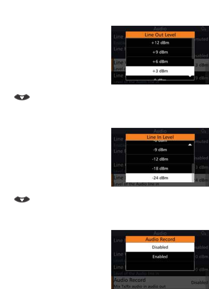
91
BARRETT 4050 HF SDR TRANSCEIVER - OPERATING AND INSTALLATION MANUAL
Line Out Level
This setting adjusts the output level
of the auxiliary 600 ohm balanced
audio output port.
Tap /LQH2XW/HYHO from the Audio
screen to display the Line Out Level
screen.
Select either: +12, +9, +6, +3, 0, -3,
-6, -9, -12 dBm.
To reveal more items, either swipe
down on the touch screen or press
.
Line In Level
This setting adjusts the input level
sensitivity of the auxiliary 600 ohm
balanced audio input.
Tap /LQH,Q/HYHO from the Audio
screen to display the Line In Level
screen.
Select either: +9, +6, +3, 0, -3, -6,
-9, -12, -18, -24 dBm.
To reveal more items, either swipe
down on the touch screen or press
.
Audio Record
This option is used to monitor con-
versations. It utilises the line audio to
listen to the received and transmitted
audio. Connect another device to
record the conversation.
Tap $XGLR5HFRUG from the Audio
screen to display the Audio Record
screen.
Select either: Disabled or Enabled.
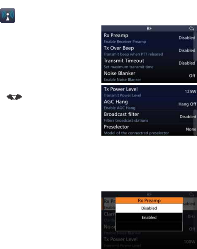
92
BARRETT 4050 HF SDR TRANSCEIVER - OPERATING AND INSTALLATION MANUAL
RF
Tap RF from the Settings screen to
display the RF screen.
$OLVWRILWHPVWKDWPD\EHFRQÀJXUHG
displays.
A brief description of each of the
items is described beneath the items.
The current status of each of the
items is displayed to the right.
To reveal more items, either swipe
down on the touch screen or press
.
Each item is described below.
Rx Preamp
(QDEOHVRUGLVDEOHVWKH5)SUHDPSOLÀHU7KHSUHDPSOLÀHUSURYLGHVDQDGGL-
WLRQDOUHFHLYHUJDLQRIG%*HQHUDOO\WKH5)SUHDPSOLÀHULVVZLWFKHGRIIZKHQ
an automatic mobile antenna is in use as these antennas have a built-in RF
SUHDPSOLÀHU
Tap Rx Preamp from the RF screen
to display the Rx Preamp screen.
Select either: Disabled or Enabled.
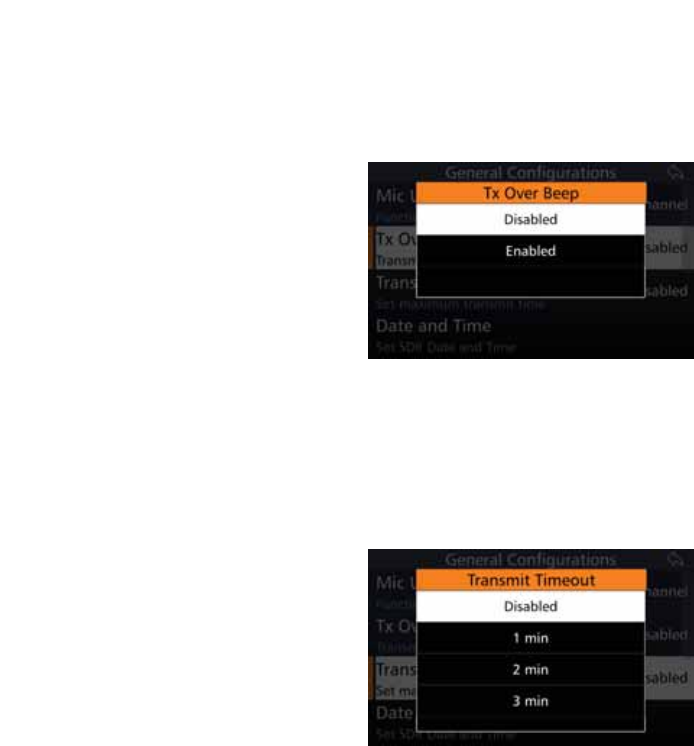
93
BARRETT 4050 HF SDR TRANSCEIVER - OPERATING AND INSTALLATION MANUAL
Tx Over Beep
When this option is selected, the Transceiver transmits a short tone after the
PTT button is released. The tone provides an audible indication to the Operator
at the remote station that the local station has stopped transmitting.
Tap 7[2YHU%HHS from the RF
screen to display the Tx Over Beep
screen.
Select either Disabled or Enabled.
Transmit Timeout
When this feature is enabled, the Transceiver will stop transmitting if the PTT
button is held on for more than the allowed time limit. For example, if the
microphone is inadvertently jammed under a seat. Releasing the PTT button
will re-enable transmission.
Tap Transmit Timeout from the RF
screen to display the Transmit Time-
out screen.
Set the maximum transmit time to
either one, two, or three minutes.
Alternatively, this transmit timeout
can be disabled.
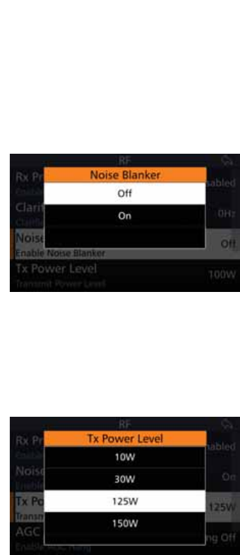
94
BARRETT 4050 HF SDR TRANSCEIVER - OPERATING AND INSTALLATION MANUAL
Noise Blanker
This setting allows the predictive noise blanker to be switched on or off. The
noise blanker is useful to reduce the interference caused within vehicles with
petrol engines.
Note: The noise blanker will not be effective in situations where for example, exter-
nal power line noise is blanketing the receiver.
Tap 1RLVH%ODQNHU from the RF
screen to display the Noise Blanker
screen.
Select either: Off or On.
Note: In certain situations noise blank-
ers can cause intermodulation in re-
ceivers. In these cases the noise blanker
should be disabled.
The noise blanker can also be con-
trolled from the Swipe menu (see
page 138).
Tx Power Level
This section sets the RF power output of the Transceiver.
Tap 7[3RZHU/HYHO from the RF
screen to display the Tx Power Level
screen.
Select either: 10 W, 30 W, 125 W, or
150 W.
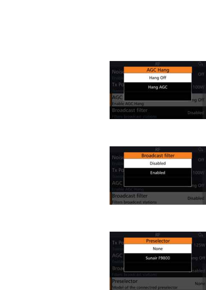
95
BARRETT 4050 HF SDR TRANSCEIVER - OPERATING AND INSTALLATION MANUAL
AGC Hang
7KLVVHFWLRQDOORZVWKH$*&FRQÀJXUDWLRQRIWKHUHFHLYHUWREHVHWWRHLWKHU
Hang AGC or Hang Off. The selection depends on the receiver environment and
should be set for optimum receiver performance. In the presence of high static
and sporadic noise, the function of the hang AGC may result in gaps in the
received signal due to the slow AGC recovery.
Tap AGC Hang from the RF screen to
display the AGC Hang screen.
Select either: Hang Off or Hang AGC.
Broadcast Filter
Tap %URDGFDVW)LOWHU from the RF
screen to display the Broadcast Filter
screen.
With the Broadcast Filter enabled,
strong broadcast signals below
0+]ZLOOEHÀOWHUHGRXW
Select either: Disabled or Enabled.
Preselector
Tap 3UHVHOHFWRU from the RF screen
to display the Preselector screen.
Select either: None or Sunair F9800.
The Preselector can be used for
selectable gain and automatic RF
overload protection.
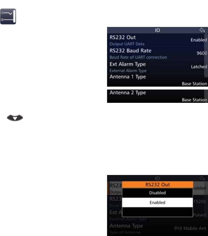
96
BARRETT 4050 HF SDR TRANSCEIVER - OPERATING AND INSTALLATION MANUAL
IO
Tap IO from the Settings screen to
display the IO screen.
$OLVWRILWHPVWKDWPD\EHFRQÀJXUHG
is displayed.
Note: Antenna 2 Type is only available if
connected to a Break out Box (BoB).
A brief description of each of the
items is described beneath the items.
The current status of each of the
items is displayed to the right.
To reveal more items, either swipe
down on the touch screen or press
.
Each item is described below.
RS232 Out
This setting enables or disables RS-232 Selcall information output from the
Transceiver via the 25 pin auxiliary connector.
Tap RS232 Out from the IO screen to
display the RS232 Out screen.
Select either: Disabled or Enabled.
Note: This command does not allow
RS-232 control of the Transceiver as
enabled when the RS-232 option is
ÀWWHG,WLVXVHGWRFRQWUROWKHRXWSXWRI
Selcall information used by some exter-
nal programs such as vehicle tracking.
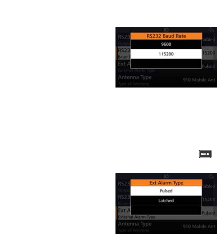
97
BARRETT 4050 HF SDR TRANSCEIVER - OPERATING AND INSTALLATION MANUAL
RS232 Baud Rate
This menu option allows the selection
of the RS232 Baud rate.
The higher the baud rate, the faster
data is sent / received. However, 9600
should be selected for compatible
devices.
Tap RS232 Baud Rate from the IO
screen to display the RS232 Baud
Rate screen.
Select either: 9600 or 115200.
EXT Alarm Type
This setting sets the action of the external alarm output when a Selcall is
received by the Transceiver. It can be set to either a pulse output (for use with
a horn) where the output is activated 15 seconds on, 15 seconds off; or a con-
stant output (for use with a rotating beacon). Both are reset by pressing
or the PTT button.
Tap Ext Alarm Type from the IO
screen to display the Ext Alarm Type
screen.
Select either: Pulsed or Latched.
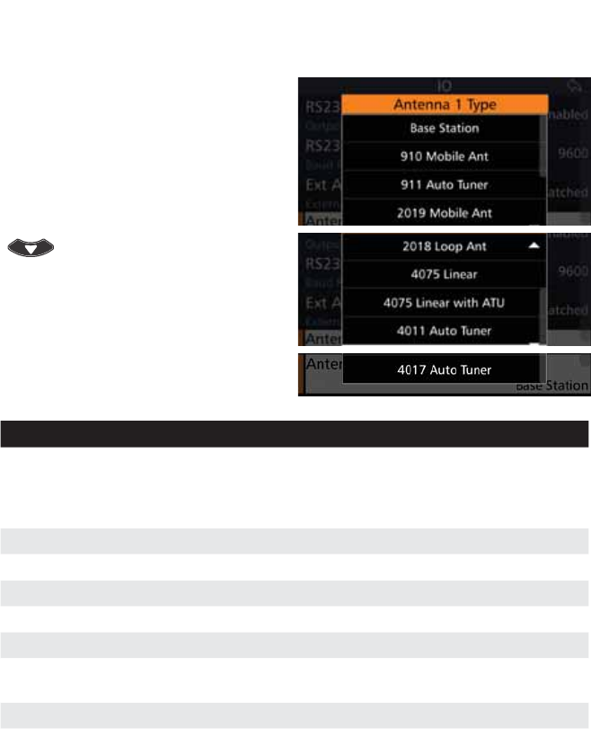
98
BARRETT 4050 HF SDR TRANSCEIVER - OPERATING AND INSTALLATION MANUAL
Antenna 1 Type
This menu sets the antenna type or
OLQHDUDPSOLÀHUXVHGZLWKWKH7UDQV-
ceiver.
Tap Antenna 1 Type from the IO
screen to display the Antenna 1 Type
screen.
To reveal more items, either swipe
down on the touch screen or press
.
Select an antenna type from the
following:
Antenna Type Select when . . .
Base Station Base station antennas such as the Barrett 2012 series are used.
No tuning signals are emitted on channel change. This selection
should also be used when operating with a Barrett 2014 manu-
al tapped whip.
910 Mobile Ant Using a Barrett 910 automatic tuning mobile antenna
911 Auto Tuner Using a Barrett 911 automatic tuner
2019 Mobile Ant Using a Barrett 2019 automatic tuning mobile HF antenna
2018 Loop Ant Using the 2018 Mobile magnetic loop HF antenna
4075 Linear 8VLQJWKH7UDQVFHLYHUZLWKD%DUUHWWVHULHVOLQHDUDPSOLÀHU
4075 Linear with
ATU
8VLQJWKH7UDQVFHLYHUZLWKD%DUUHWWVHULHVOLQHDUDPSOLÀHU
with ATU.
4011 Auto Tuner Using a Barrett 4011 automatic tuner
4017 Auto Tuner Using a Barrett 4017 automatic tuner
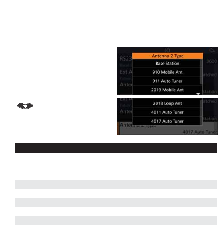
99
BARRETT 4050 HF SDR TRANSCEIVER - OPERATING AND INSTALLATION MANUAL
Antenna 2 Type
This option is only available if connected to a Break out Box (BoB).
Note: 4075 Linear and 4075 Linear with ATU is not available for Antenna 2 Type.
This menu sets the antenna type
which may be used with the Trans-
ceiver when connected to a BoB.
Tap Antenna 2 Type from the IO
screen to display the Antenna 2 Type
screen.
To reveal more items, either swipe
down on the touch screen or press
.
Select an antenna type from the
following:
Antenna Type Select when . . .
Base Station Base station antennas such as the Barrett 2012 series are used.
No tuning signals are emitted on channel change. This selection
should also be used when operating with a Barrett 2014 manu-
al tapped whip.
910 Mobile Ant Using a Barrett 910 automatic tuning mobile antenna
911 Auto Tuner Using a Barrett 911 automatic tuner
2019 Mobile Ant Using a Barrett 2019 automatic tuning mobile HF antenna
2018 Loop Ant Using the 2018 Mobile magnetic loop HF antenna
4011 Auto Tuner Using a Barrett 4011 automatic tuner
4017 Auto Tuner Using a Barrett 4017 automatic tuner

100
BARRETT 4050 HF SDR TRANSCEIVER - OPERATING AND INSTALLATION MANUAL
ALE
7KH%DUUHWW$XWRPDWLF/LQN(VWDEOLVKPHQW$/(FRQWUROOHURSWLRQVLPSOLÀHVWKH
operation of HF networks by automating many of the procedures necessary to
establish and maintain an HF link.
The ALE controller option provides complete inter-operability as required by
FED-STD-1045 and U.S. MIL-STD-188-141C standards.
HF network stations equipped with ALE controllers automatically scan a
pre-selected set of channels, listening for ALE calls.
If sounding is selected, stations will send out sounding calls to other stations at
periodic intervals. These signals are analysed for link quality and stored in the
sounded stations. All stations gradually build up a table of parameters which
GHWHUPLQHWKHEHVWFKDQQHOVWRXVHWROLQNEHWZHHQVSHFLÀFVWDWLRQV7KHVH
tables are used by the ALE controller to determine the best channel to connect
on when commanded by its Operator to communicate with another station.
The ALE controller’s memory stores up to 8,000 sets of LQA information, 100
FKDQQHOFRQÀJXUDWLRQVDQGDFRPELQDWLRQRIDGGUHVVFRQÀJXUDWLRQV
(self-address and other address). Plus, it has the ability to save unknown
station information in an Auto Fill queue. This allows new stations to join the
ALE network without having to manually re-program the network settings of
HDFK7UDQVFHLYHULQWKHQHWZRUN7KHUHDUHVORWVDYDLODEOHIRU$/($XWRÀOO
addresses.
ALE Set-up Overview
The ALE network parameters are determined by a network supervisor. The net-
work supervisor programs all the Transceivers in the network with the required
addressing and channel information using the Barrett 4050 HF SDR Program-
PLQJ6RIWZDUH31%&$SULRUWRÀHOGXVDJH
The Barrett 4050 HF SDR Programming software (P/N BCA40001) is used to
transfer pre-determined network information to each Transceiver.
As ALE’s prime purpose is to automate many of the procedures necessary to
establish and maintain an HF link, it is only necessary for the Operator to enter
the desired station to call and activate the ALE call sequence as described in
this section.
Various operational parameters can be changed within the protected menu
ALE section as required by the Operator. The ALE Settings section on page 101
describes these functions.
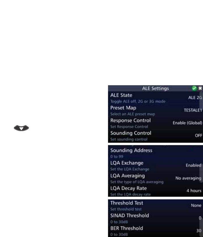
101
BARRETT 4050 HF SDR TRANSCEIVER - OPERATING AND INSTALLATION MANUAL
Combined ALE / Selective Call - Overview
The combined ALE / Selective Call capability allows the user to receive and
transmit ALE and Selcall type calls on channels which are programmed for
ALE scan but also have Selcall enabled on them. This means that during ALE
channel scanning, the Transceiver can accept incoming Selcalls. However, this
feature can only be used if the ALE scan rate is set to 2 channels per second
(set in the Barrett 4050 HF SDR Programming Software (P/N BCA40001)).
ALE State Settings for 2G
Tap ALE from the Settings screen to
display the ALE Settings screen.
$OLVWRILWHPVWKDWPD\EHFRQÀJXUHG
is displayed.
To reveal more items, either swipe
down on the touch screen or press
.
Note: The list shown opposite is for an
ALE state of 2G mode only.
A brief description of each of the
items is described beneath the items.
The current status of each of the
items is displayed to the right.
Each item is described below.
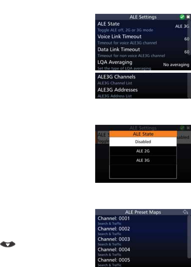
102
BARRETT 4050 HF SDR TRANSCEIVER - OPERATING AND INSTALLATION MANUAL
Note: The ALE Settings screen for an
ALE State of 3G mode (shown oppo-
site) differs from 2G mode.
The list of items for 2G mode is de-
scribed below.
The list of items for 3G mode is
shown on page 107.
ALE State
Tap ALE State from the ALE Set-
tings screen to display the ALE State
screen.
Select either: Disabled, ALE 2G, or
ALE 3G.
Depending on your choice, the list of
items will change in the ALE Settings
screen.
Preset Map
Tap Preset Map from the ALE Set-
tings screen to display the ALE Preset
Maps screen.
To reveal more items, either swipe
down on the touch screen or press
.
Tap an ALE Preset Map from the
displayed list.
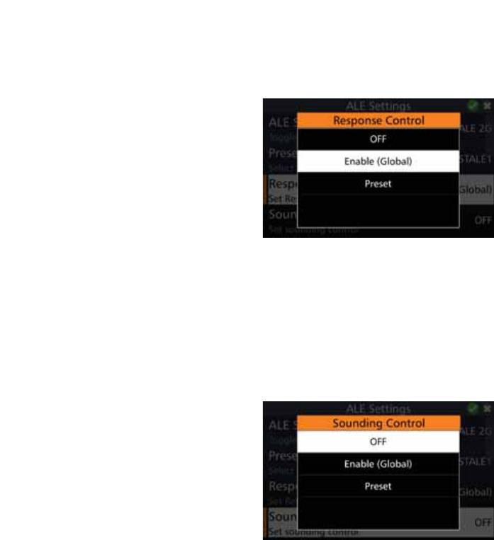
103
BARRETT 4050 HF SDR TRANSCEIVER - OPERATING AND INSTALLATION MANUAL
Response Control
To allow the ALE system to respond to any incoming ALE calls (including auto-
matic soundings), ensure the Response Control is set to Enabled.
Tap Response Control from the
ALE Settings screen to display the
Response Control screen.
Select either: Off, Enable (Global), or
Preset.
Sounding Control
ALE operates normally both transmitting and receiving sounds when Sounding
Control is set to Enable. In some circumstances, it is desirable not to transmit
soundings. In this case, Sounding Control is set to Disable. Sounding is limited
WRFHUWDLQFKDQQHOVSUHSURJUDPPHGE\WKH$/(ÀOOSURJUDP7KH$/(V\VWHP
will continue to make and respond to calls (depending on the Response Control
settings).
Tap Sounding Control from the
ALE Settings screen to display the
Sounding Control screen.
Select either: Off, Enable (Global), or
Preset.
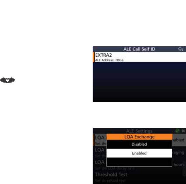
104
BARRETT 4050 HF SDR TRANSCEIVER - OPERATING AND INSTALLATION MANUAL
Sounding Address
&RQÀJXUHVWKHVHOIDGGUHVVXVHGGXULQJDQDXWRPDWLFVRXQGLQJ6RXQGLQJ
Control must be set to Global Sounding On). If the sounding control is set to
an individual preset, the address used is dependent on the active channel.
Tap Sounding Address from the
ALE Settings screen to display the ALE
Call Self ID screen.
To reveal more items, either swipe
down on the touch screen or press
.
Tap an ALE Call Self ID from the dis-
played list.
LQA Exchange
This option enables or disables the
exchange of LQA information with
other stations.
Tap /4$([FKDQJH from the ALE
Settings screen to display the LQA
Exchange screen.
Select either: Disabled or Enabled.
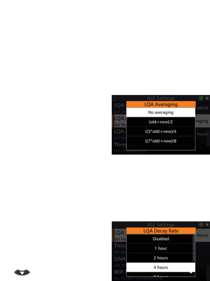
105
BARRETT 4050 HF SDR TRANSCEIVER - OPERATING AND INSTALLATION MANUAL
LQA Averaging
This option sets the method used to update an existing link quality value stored
in ALE processor memory when the new link quality value is worse than the
stored value.
The option can be set to either replace the old values with the new values or
replace the old values with different weighted averages of the old values and
new readings.
Averaging reduces the effect that one bad reading might otherwise have on a
perfect channel. If a new reading is better than an old value, the old value is
replaced by the reading. There are four different averaging formulas available:
Tap /4$$YHUDJLQJ from the ALE
Settings screen to display the LQA
Averaging screen.
Select either:
No Averaging,
(old + new)/2,
((3*old)+new)/4, or
((7*old)+new)/8.
LQA Decay Rate
7KLVRSWLRQVHWVWKHDUWLÀFLDOGHFD\UDWHIRUWKHOLQNTXDOLW\LQIRUPDWLRQWKDWLV
stored in the link quality table within the ALE processor.
Switching the sounding off and setting a decay rate of two hours would result
in the recording of a perfect channel (100% channel quality) decaying to an
unusable channel (0% channel quality) over a period of two hours.
Tap /4$'HFD\5DWH from the ALE
Settings screen to display the LQA
Decay Rate screen.
Select either: Disabled, 1, 2, 4, 8, 24,
or 48 hours.
To reveal more items, either swipe
down on the touch screen or press
.
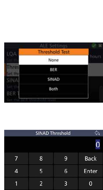
106
BARRETT 4050 HF SDR TRANSCEIVER - OPERATING AND INSTALLATION MANUAL
Threshold Test
Used to select which type of threshold test is used to determine what quality
ALE channel is acceptable for communication.
Tap Threshold Test from the ALE
Settings screen to display the Thresh-
old Test screen.
Select either: None, BER, SINAD, or
Both.
SINAD Threshold
This option sets the SINAD threshold
(in dB) at which an ALE channel is
considered usable.
Tap 6,1$'7KUHVKROG from the ALE
Settings screen to display the SINAD
Threshold screen.
Type a value between 0 and 30 dB,
then tap Enter.
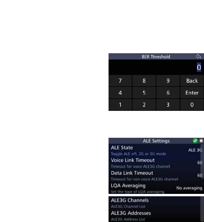
107
BARRETT 4050 HF SDR TRANSCEIVER - OPERATING AND INSTALLATION MANUAL
BER Threshold
This option selects the BER threshold at which an ALE channel is considered
usable. If the required BER is not reached in the reply from the remote station,
the link establishment process is rejected. Depending on the retry setting, the
link establishment would continue on another link.
Tap BER Threshold from the ALE
Settings screen to display the BER
Threshold screen.
Type a value between 0 and 30 dB,
then tap Enter.
Selecting 30 effectively means that all
links are allowed.
ALE State Settings for 3G
Selecting ALE State 3G Mode displays
a different menu shown opposite.
These menu items are described
below.
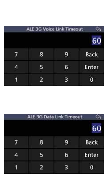
108
BARRETT 4050 HF SDR TRANSCEIVER - OPERATING AND INSTALLATION MANUAL
Voice Link Timeout
This option is only available if the ALE
State is set to 3G.
Tap 9RLFH/LQN7LPHRXW from the
ALE Settings screen to display the ALE
3G Voice Link Timeout screen.
Type the number of seconds and tap
Enter to save and return to the ALE
Settings screen.
Data Link Timeout
This option is only available if the ALE
State is set to 3G.
Tap 'DWD/LQN7LPHRXW from the
ALE Settings screen to display the ALE
3G Data Link Timeout screen.
Type the number of seconds and tap
Enter to save and return to the ALE
Settings screen.
LQA Averaging
This option sets the method used to update an existing link quality value stored
in ALE processor memory when the new link quality value is worse than the
stored value.
The option can be set to either replace the old values with the new values or
replace the old values with different weighted averages of the old values and
new readings.
Averaging reduces the effect that one bad reading might otherwise have on a
perfect channel. If a new reading is better than an old value, the old value is
replaced by the reading. There are four different averaging formulas available:
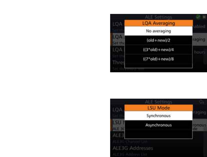
109
BARRETT 4050 HF SDR TRANSCEIVER - OPERATING AND INSTALLATION MANUAL
Tap /4$$YHUDJLQJ from the ALE
Settings screen to display the LQA
Averaging screen.
Select either:
No Averaging,
(old + new)/2,
((3*old)+new)/4, or
((7*old)+new)/8.
LSU Mode
Link Set Up is only available if the ALE
State is set to 3G.
Tap /680RGH from the ALE Settings
screen to display the LSU Mode
screen.
From the drop-down menu select
either:
• Synchronous
Select the LSU mode to Synchro-
nous to set all the stations to be
in synch. However, all Transceivers
have to have GPS enabled so they
can all scan at the same interval
on the same channel. Calls only
need a short duration to enable
other Transceivers to hear at the
same time. The advantages of
synchronous include: shorter calls,
shorter soundings, and reduced
QHWZRUNWUDIÀF
• Asynchronous.
If there is no GPS signal, set the
LSU mode to asynchronous. How-
ever, longer calls are necessary
to enable successful scans. GPS
is not necessary and the network
doesn’t have to be synchronised.
Note that the linking will take
longer.
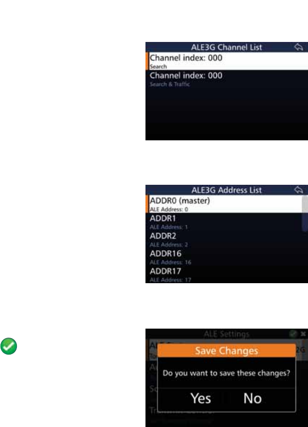
110
BARRETT 4050 HF SDR TRANSCEIVER - OPERATING AND INSTALLATION MANUAL
ALE 3G Channels
This option is only available if the ALE
State is set to 3G.
Tap ALE3G Channels from the ALE
Settings screen to display the ALE 3G
Channel List screen.
Tap the channel from the displayed
list.
ALE 3G Addresses
This option is only available if the ALE
State is set to 3G.
Tap ALE3G Addresses from the ALE
Settings screen to display the ALE 3G
Address List screen.
Tap the address from the displayed
list.
Save the ALE Settings
$IWHUFRQÀJXULQJWKHDERYHLWHPV
tap to save the ALE Settings.
$FRQÀUPDWLRQPHVVDJHGLVSOD\V
Tap Yes.
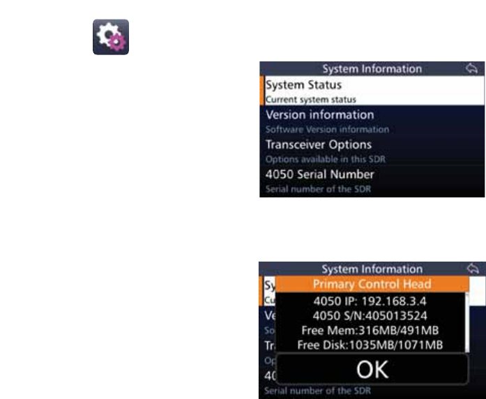
111
BARRETT 4050 HF SDR TRANSCEIVER - OPERATING AND INSTALLATION MANUAL
System Info
Tap System Info from the Settings
screen to display the System Informa-
tion screen.
A list of items that may be viewed is
displayed.
A brief description of each of the
items is described beneath the items.
Each item is described below.
System Status
Tap System Status from the System
Information screen to display the
System Information screen.
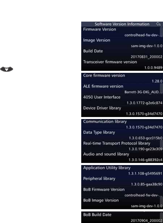
112
BARRETT 4050 HF SDR TRANSCEIVER - OPERATING AND INSTALLATION MANUAL
Version Information
Tap 9HUVLRQ,QIRUPDWLRQ from the
System Information screen to display
the Software Version Information
screen.
A list of items that may be viewed is
displayed.
To reveal more items, either swipe
down on the touch screen or press
.
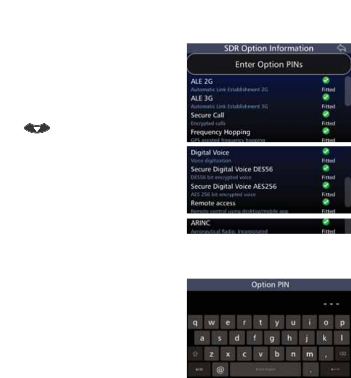
113
BARRETT 4050 HF SDR TRANSCEIVER - OPERATING AND INSTALLATION MANUAL
Transceiver Options
Tap 7UDQVFHLYHU2SWLRQV from the
System Information screen to display
the SDR Option Information screen.
A list of items that may be viewed is
displayed.
To reveal more items, either swipe
down on the touch screen or press
.
Tap each option to toggle between
enabling or disabling the options.
Enter Option PINs
Tap (QWHU2SWLRQ3,1V from the
SDR Option Information screen to
display the Option PIN screen.
Tap the appropriate characters from
the keyboard into the Option PIN
ÀHOG
Tap Enter to save and return to the
SDR Option Information screen.
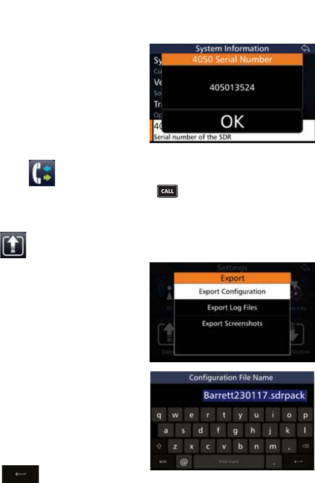
114
BARRETT 4050 HF SDR TRANSCEIVER - OPERATING AND INSTALLATION MANUAL
4050 Serial Number
Tap 6HULDO1XPEHUfrom the
System Information screen to display
the 4050 Serial Number screen.
The 4050 serial number displays.
Tap Ok to close the 4050 Serial Num-
ber screen and return to the System
Information screen.
Call History
This function is also available by pressing .
Refer to page 47 for further information.
Export
7RH[SRUWWKHGHYLFH·VFRQÀJXUD-
tion settings, insert a USB into the
device’s USB socket. Use either the
front USB socket using a mini USB or
the USB socket located at the top of
the device.
Tap Export from the Settings screen
to display the Export screen.
7DS([SRUW&RQÀJXUDWLRQWRGLVSOD\
WKH&RQÀJXUDWLRQ)LOH1DPHVFUHHQ
The default name displays. Use the
keyboard to type an alternative name
RIWKHFRQÀJÀOHWRH[SRUWWRWKH
USB.
1RWH7KHÀOHH[WHQVLRQVGUSDFNPXVW
not be changed.
Tap to save.
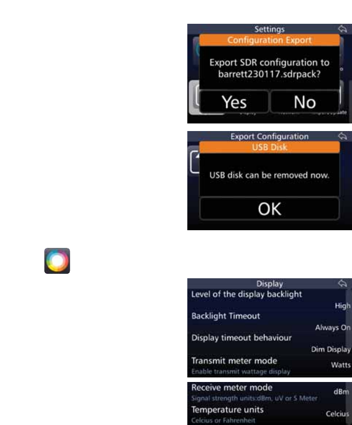
115
BARRETT 4050 HF SDR TRANSCEIVER - OPERATING AND INSTALLATION MANUAL
$FRQÀUPDWLRQPHVVDJHGLVSOD\V
Tap Yes.
7KH([SRUW&RQÀJXUDWLRQVFUHHQ
displays showing a progress bar con-
ÀUPLQJWKHSURJUHVVRIWKHH[SRUW
When prompted, tap 2. and remove
the USB.
Display
Tap 'LVSOD\ from the Settings screen
to display the Display screen.
$OLVWRILWHPVWKDWPD\EHFRQÀJXUHG
is displayed.
A brief description of each of the
items is described beneath the items.
The current status of each of the
items is displayed to the right.
Each item is described below.
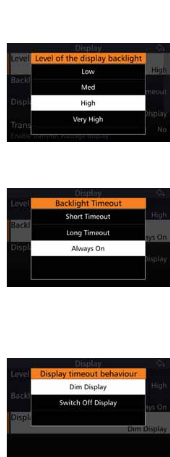
116
BARRETT 4050 HF SDR TRANSCEIVER - OPERATING AND INSTALLATION MANUAL
Level of Display Backlight
Adjust the backlight level on the LCD
display to one of three brightness
levels.
Tap /HYHORIWKH'LVSOD\%DFNOLJKW
from the Display screen to display the
Level of the Display Backlight screen.
Select either: Low, Medium, High or
Very High.
Backlight Timeout
Set the backlight timeout after the
last key press.
Tap %DFNOLJKW7LPHRXW from the
Display screen to display the Back-
light Timeout screen.
Select either: Short Timeout (1 min-
ute), Long Timeout (3 minutes), or
Always On.
Note: The Transceiver’s power con-
sumption is reduced when the back-
light has a short timeout.
Display Timeout Behaviour
Tap 'LVSOD\7LPHRXW%HKDYLRXU
from the Display screen to display the
Display Timeout Behaviour screen.
Select either: Dim Display or Switch
Off Display.
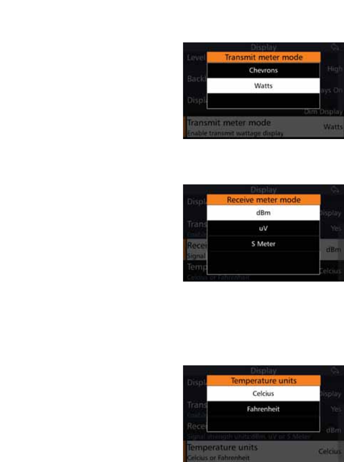
117
BARRETT 4050 HF SDR TRANSCEIVER - OPERATING AND INSTALLATION MANUAL
Transmit Meter Mode
This will enable the display to either
show or hide the transmit wattage.
Tap Transmit Meter Mode from
the Display screen to display the
Transmit Meter Mode screen.
Select either: Chevrons or Watts.
Receive Meter Mode
This will enable the display to show
different units of value for the Re-
ceive Mode’s signal strength.
dBm measures the units in decibels,
uV measures the units in microvolts,
and S Meter measures the units in S
(strength) values. For example,
1 (weakest) to 7 (strongest).
Tap 5HFHLYH0HWHU0RGH from the
Display screen to display the Receive
Meter Mode screen.
Select either: dBm, uV, or S Meter.
Temperature Units
This will enable the SDR to show
which temperature units to display.
Tap 7HPSHUDWXUH8QLWV from the
Display screen to display the Tem-
perature Units screen.
Select either: Celsius or Fahrenheit.
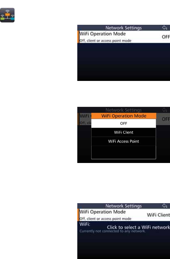
118
BARRETT 4050 HF SDR TRANSCEIVER - OPERATING AND INSTALLATION MANUAL
Network
Tap 1HWZRUN from the Settings
screen to display the Network Set-
tings screen.
The current status of the WiFi Opera-
tion Mode is displayed to the right
Tap WiFi Operation Mode to
change the status.
WiFi Operation Mode
Tap WiFi Operation Mode from the
Network Settings screen to display
the WiFi Operation Mode screen.
Select either: Off, WiFi Client, or WiFi
Access Point.
$:L)LFOLHQWFRQQHFWVWRDVSHFLÀHG
Internet IP address and port.
A WiFi Access Point is a device that
creates a wireless local area network,
or WLAN, and projects a Wi-Fi signal
to a designated area.
WiFi Client
If WiFi Client was selected from
the WiFi Operation Mode screen, the
following screen displays.
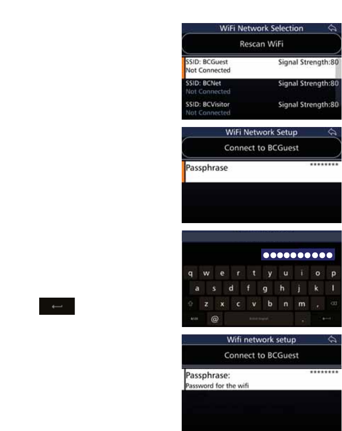
119
BARRETT 4050 HF SDR TRANSCEIVER - OPERATING AND INSTALLATION MANUAL
Tap WiFi from the Network Settings
screen to display the WiFi Network
Selection screen.
Tap 5HVFDQ:L)L if necessary to
display more WiFi networks.
Select a WiFi network to connect to
from the list.
You may be prompted for a password
in order to connect to your chosen
network.
Tap the 3DVVSKUDVHÀHOG from the
WiFi Network Setup screen to display
the WiFi Passphrase screen.
Tap the appropriate characters from
the keyboard into the WiFi Pass-
SKUDVHÀHOG
Tap to save and return to
the WiFi Network Setup screen.
WiFi Passphrase (10/255)
The password entered in the Pass-
SKUDVHÀHOGLVQRZGLVSOD\HGDV
asterisks.
Tap &RQQHFWWR%&*XHVW.
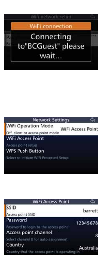
120
BARRETT 4050 HF SDR TRANSCEIVER - OPERATING AND INSTALLATION MANUAL
$PHVVDJHGLVSOD\VFRQÀUPLQJWKDW
your selected network is connecting.
A further message displays con-
ÀUPLQJWKH:L)LFRQQHFWLRQHLWKHU
successful or failed.
WiFi Access Point Mode
If :L)L$FFHVV3RLQW was select-
ed from the WiFi Operation Mode
screen, the following screen displays.
WiFI Access Point Setup
Tap :L)L$FFHVV3RLQW from the Net-
work Settings screen to display the
WiFi Access Point screen.
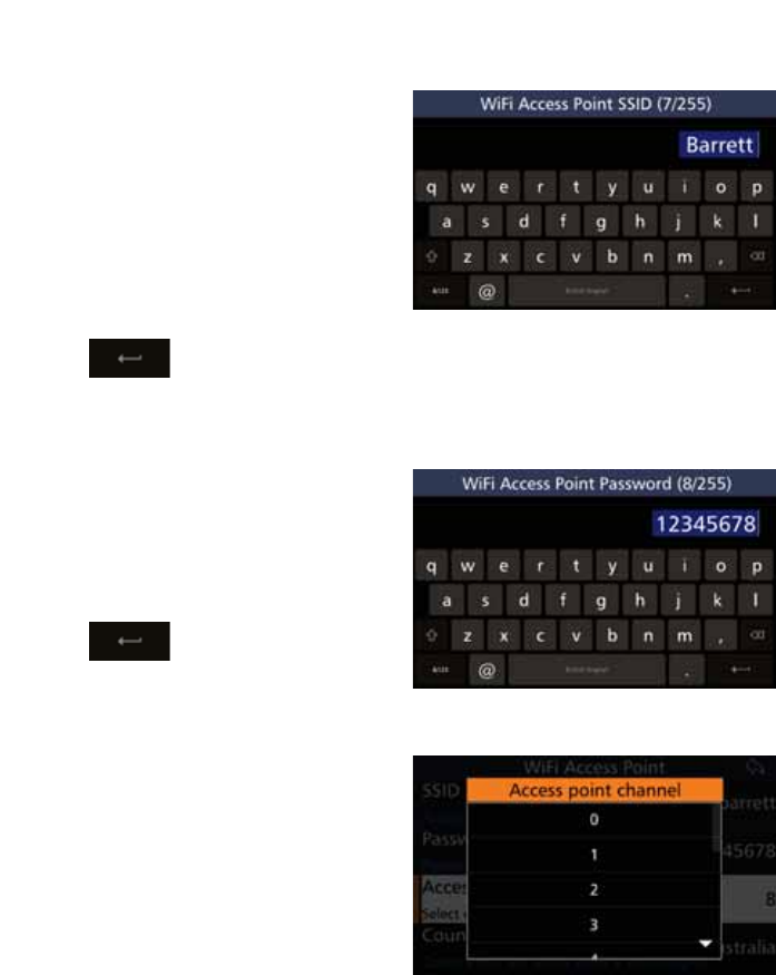
121
BARRETT 4050 HF SDR TRANSCEIVER - OPERATING AND INSTALLATION MANUAL
66,'
Tap 66,'6HUYLFH6HW,GHQWLÀHU
from the WiFi Access Point screen to
display the WiFi Access Point SSID
screen. The numbers in the parenthe-
sis indicate how many characters you
have used / total number of charac-
ters allowed.
Tap the appropriate characters from
the keyboard into the WiFi Access
3RLQW66,'ÀHOG
Tap to save and return to
the WiFi Access Point screen.
Password
Tap Password from the WiFi Access
Point screen to display the WiFi Ac-
cess Point Password screen.
Tap the appropriate characters from
the keyboard into the WiFi Access
3RLQW3DVVZRUGÀHOG
Tap to save and return to
the WiFi Access Point screen.
$FFHVV3RLQW&KDQQHO
Tap $FFHVV3RLQW&KDQQHO from the
WiFi Access Point screen to display
the Access Point Channel screen.
Select from channel 0 to 13. Channel
0 is for automatic assignment.
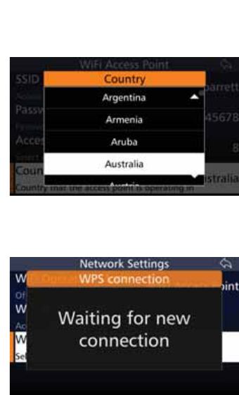
122
BARRETT 4050 HF SDR TRANSCEIVER - OPERATING AND INSTALLATION MANUAL
Country
Tap Country from the WiFi Access
Point screen to display the Country
screen.
Select the appropriate country.
WPS Push Button
Tap WPS Push Button (WiFi Pro-
tected Setup) from the WiFi Access
Point Mode screen to display the WPS
Connection screen.
This option will initiate the WiFi pro-
tection setup.
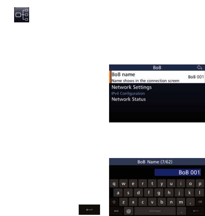
123
BARRETT 4050 HF SDR TRANSCEIVER - OPERATING AND INSTALLATION MANUAL
BoB
The Break out Box (BoB) icon only displays if the 4050 HF SDR Transceiver is
connected to a BoB.
The BoB is designed to connect two antennas or two ATUs to the 4050 HF SDR
Transceiver. Refer to the Break out Box Installation Manual (P/N BCM400500)
for further information.
This menu setting option is only avail-
able if the Transceiver is connected to
a Break out Box (BoB)
Tap BoB from the Settings screen to
display the BoB screen.
$OLVWRILWHPVWKDWPD\EHFRQÀJXUHG
displays. A brief description of each
of the items is described beneath the
items.
Each item is described below.
BoB Name
Tap %R%1DPH from the BoB screen
to display the BoB Name screen.
The numbers in the parenthesis indi-
cate how many characters you have
used / total number of characters
allowed.
Use the keyboard to type or edit the
name of the BoB, then tap
to save.
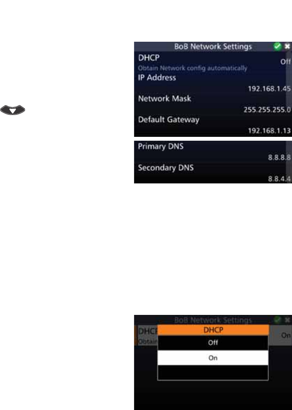
124
BARRETT 4050 HF SDR TRANSCEIVER - OPERATING AND INSTALLATION MANUAL
Network Settings
Tap 1HWZRUN6HWWLQJV from the BoB
screen to display the BoB Network
Settings screen.
$OLVWRILWHPVWKDWPD\EHFRQÀJXUHG
displays. To reveal more items, either
swipe down on the touch screen or
press .
A brief description of each of the
LWHPVZKLFKPD\EHFRQÀJXUHGLV
described beneath the items.
The current status of each of the
items is displayed to the right.
Each item on the list is described
below.
DHCP
'\QDPLF+RVW&RQÀJXUDWLRQ3URWRFRO'+&3LVDFOLHQWVHUYHUSURWRFROWKDW
automatically provides an Internet Protocol (IP) host with its IP address and
RWKHUUHODWHGFRQÀJXUDWLRQLQIRUPDWLRQVXFKDVWKHVXEQHWPDVNDQGGHIDXOW
gateway.
The DHCP is controlled by a DHCP server that dynamically distributes network
FRQÀJXUDWLRQSDUDPHWHUVVXFKDV,3DGGUHVVHVIRULQWHUIDFHVDQGVHUYLFHV
Tap '+&3 from the BoB Network
Settings screen to display the DHCP
screen.
Select Off to enter the network set-
tings manually, or On to automatical-
O\REWDLQWKHQHWZRUNFRQÀJXUDWLRQ
settings.
7KHPDQXDOQHWZRUNFRQÀJXUDWLRQ
settings are described below.
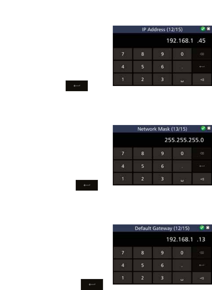
125
BARRETT 4050 HF SDR TRANSCEIVER - OPERATING AND INSTALLATION MANUAL
IP Address
Tap IP Address from the BoB Net-
work Settings screen to display the IP
Address screen.
The numbers in the parenthesis indi-
cate how many characters you have
used / total number of characters
allowed.
Use the keyboard to type or edit the
IP Address, then tap
y
p
to
save.
Network Mask
Tap 1HWZRUN0DVN from the BoB
Network Settings screen to display
the Network Mask screen.
The numbers in the parenthesis indi-
cate how many characters you have
used / total number of characters
allowed.
Use the keyboard to type or edit the
Network Mask, then tap to
save.
Default Gateway
Tap 'HIDXOW*DWHZD\ from the BoB
Network Settings screen to display
the Default Gateway screen.
The numbers in the parenthesis indi-
cate how many characters you have
used / total number of characters
allowed.
Use the keyboard to type or edit the
Default Gateway, then tap
to save.
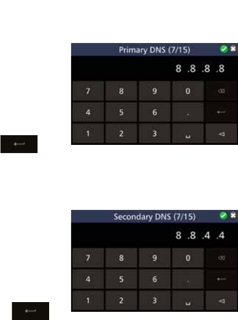
126
BARRETT 4050 HF SDR TRANSCEIVER - OPERATING AND INSTALLATION MANUAL
Primary DNS
Tap 3ULPDU\'16 from the BoB Net-
work Settings screen to display the
Primary DNS screen.
The numbers in the parenthesis indi-
cate how many characters you have
used / total number of characters
allowed.
Use the keyboard to type or edit the
Primary DNS, then tap
p
p
p
to
save.
Secondary DNS
Tap 6HFRQGDU\'16 from the BoB
Network Settings screen to display
the Secondary DNS screen.
The numbers in the parenthesis indi-
cate how many characters you have
used / total number of characters
allowed.
Use the keyboard to type or edit the
Secondary DNS, then tap to
save.
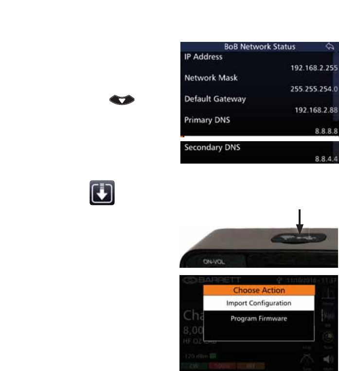
127
BARRETT 4050 HF SDR TRANSCEIVER - OPERATING AND INSTALLATION MANUAL
Network Status
Tap 1HWZRUN6WDWXV from the BoB
screen to display the BoB Network
Status screen.
A list of items display. To reveal more
items, either swipe down on the
touch screen or press .
The current setting of each of the
items is displayed to the right.
Import / Update
To update the Transceiver, insert a
thumb drive containing the update
ÀOHVLQWRWKH86%VRFNHWRQWRSRI
the front panel.
Tap ,PSRUW8SGDWH from the
Settings screen to display the Choose
Action screen.
6HOHFWHLWKHU,PSRUW&RQÀJXUDWLRQRU
Program Firmware.
These options are described below.
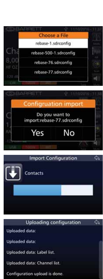
128
BARRETT 4050 HF SDR TRANSCEIVER - OPERATING AND INSTALLATION MANUAL
,PSRUW&RQÀJXUDWLRQ
7RXSGDWHWKHFRQÀJXUDWLRQWDS
,PSRUW&RQÀJXUDWLRQ from the
Choose Action screen described
above.
The Choose a File screen displays.
6HOHFWWKHUHTXLUHGÀOHWRLPSRUW
$FRQÀUPDWLRQPHVVDJHGLVSOD\V
DVNLQJLIWKHVHOHFWHGFRQÀJÀOHLVWR
be imported.
Tap YesWRGLVSOD\WKH,PSRUW&RQÀJ-
uration screen.
A progress bar indicates the progress
of the import.
7KH8SORDGLQJ&RQÀJXUDWLRQVFUHHQ
displays showing the progress and
completion of the upload.
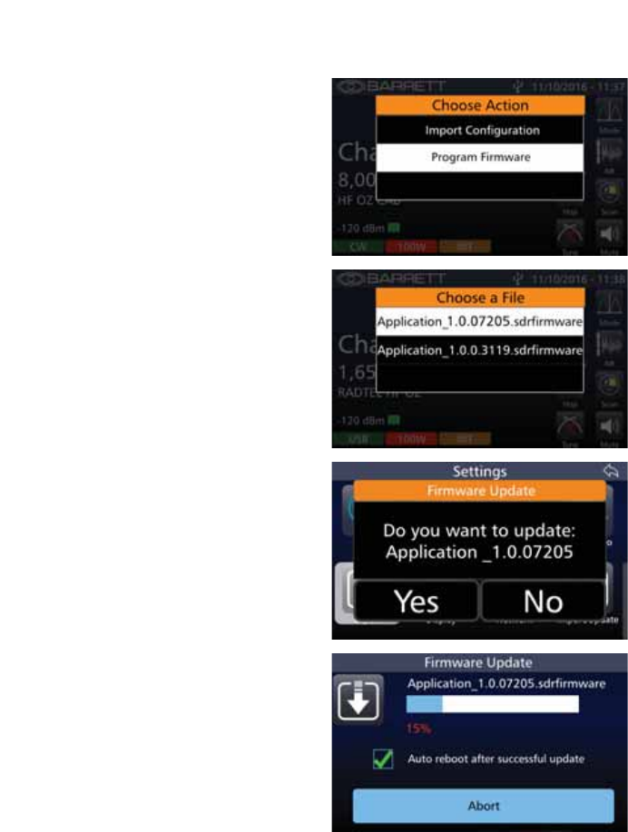
129
BARRETT 4050 HF SDR TRANSCEIVER - OPERATING AND INSTALLATION MANUAL
Program Firmware
7RXSGDWHWKHÀUPZDUHWDSPro-
gram Firmware from the Choose
Action screen described above.
The Choose a File screen displays.
6HOHFWWKHUHTXLUHGÀOHWRLPSRUW
Tap YesWRFRQÀUPWKHÀOHLPSRUW
The Firmware Update screen displays
showing the progress of the process.
Tap the checkbox to automatically
reboot after a successful update.
Tap Abort to stop the process.
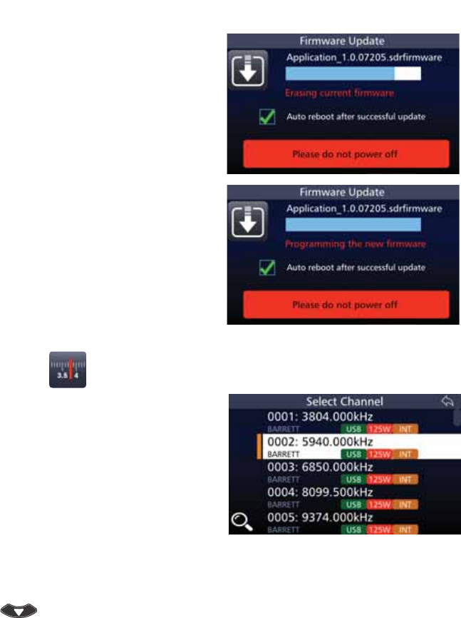
130
BARRETT 4050 HF SDR TRANSCEIVER - OPERATING AND INSTALLATION MANUAL
'XULQJWKHSURFHVVWKHFXUUHQWÀUP-
ware will be erased.
Warning: During this stage, do not
power off.
7KHÀQDOSURFHVVLQGLFDWHVWKDWWKH
QHZÀUPZDUHZLOOEHSURJUDPPHG
Warning: During this stage, do not
power off.
The Transceiver will automatically
reboot after the update has been
successful.
Channels
Tap Channels from the Home screen
to display the Select Channel screen.
A list of channels along with a brief
description of the channel’s attri-
butes is displayed.
For the highlighted example shown
opposite, the Channel number 0002
has a channel label BARRETT; a
frequency of 5940 kHz; USB mode;
125 W transmit power; and an Inter-
national Selective Call mode.
To reveal more channels, either swipe
down on the touch screen or press
.
To add a channel, see page 61.
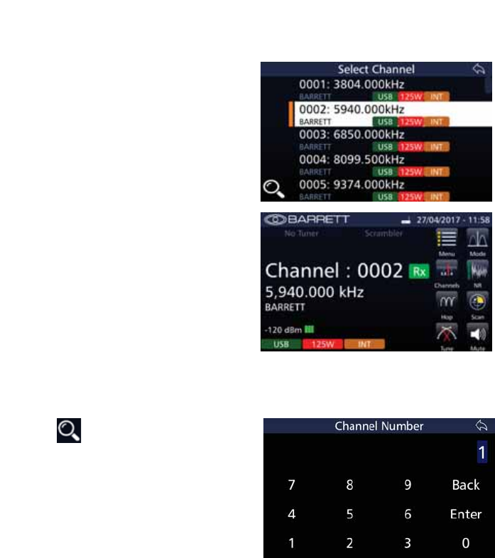
131
BARRETT 4050 HF SDR TRANSCEIVER - OPERATING AND INSTALLATION MANUAL
Selecting a Channel
Tap Channels from the Home screen
to display the Select Channel screen.
Select the desired channel.
The selected channel now displays
on the Home screen.
The example shows the Channel
number 0002 has a channel label
BARRETT; a frequency of 5940 kHz;
USB mode; 125 W transmit power;
and an International Selective Call
mode. It also shows that the channel
has -120 dBm and is receiving.
Search For a Channel
Tap from the Select Channel
screen to display the Channel Num-
ber screen.
Tap the appropriate digits for the
search, then tap Enter.

132
BARRETT 4050 HF SDR TRANSCEIVER - OPERATING AND INSTALLATION MANUAL
Hop
This option requires an Export Permit.
The Transceiver employs a unique frequency
hopping system that uses an external ESU
(Encryption Synchronisation Unit).
Note: The external ESU must be connected
and providing valid data for the frequency
hopping system to operate.
Selecting the Hop Band
Select a channel which is used for normal / clear transmission based on normal
procedures used when using an HF system. This channel frequency and mode is
used by the Transceiver to determine the hop band.
Note: The reference frequency is NOT a centre frequency for the hop band. It simply
determines which of the preset hop bands are selected.
Entering the Security Code
For hopping PIN code entry, refer to SDR Options and Option PINs on page
113. The security PIN code is based on the information below.
Security Codes and Bandwidths
Security codes 00000000 to 19999999 are used for hopping ± 2 kHz
Security codes 20000000 to 49999999 are used for hopping ± 16 kHz
Security codes 50000000 to 99999999 are used for hopping ± 128 kHz
Hopping up to ± 2 kHz is useful for narrow band antennas such as when using
antenna tuners in manpack operation.
Hopping up to ± 128 kHz can be used with wideband antennas such as base
station broadband antennas.
Once entered, the security code for security reasons can never be retrieved or
viewed.

133
BARRETT 4050 HF SDR TRANSCEIVER - OPERATING AND INSTALLATION MANUAL
To Enable Hopping Mode
Tap Hop from the Home screen to
begin the hopping sequence.
As soon as the display indicates
“Hopping Mode“, communicating
with other stations using the same
channel frequency and the same hop-
ping code, may commence.
To Disable Hopping Mode
Either tap Hop or press to dis-
able hopping mode.
The display indicates “Hopping Can-
celled“.
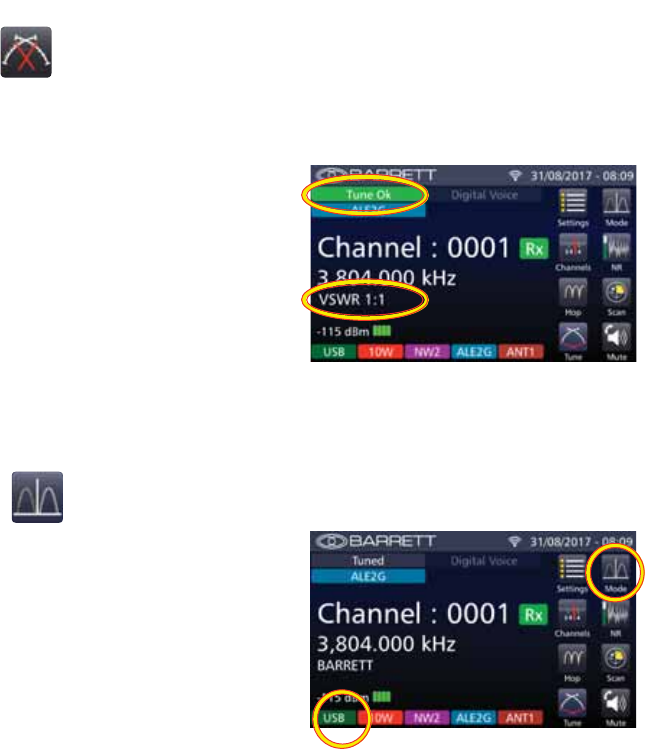
134
BARRETT 4050 HF SDR TRANSCEIVER - OPERATING AND INSTALLATION MANUAL
Tune
When tuning, the Transceiver will transmit, at the power level selected, a carrier
on the channel selected, at 1.6 kHz above the Suppressed Carrier Frequency
(SCF) (displayed frequency) of that channel.
Tap and hold Tune from the Home
screen for three seconds to begin
the automated tuning sequence.
The keypad will illuminate red whilst
the Transceiver is tuning.
When the tune process is completed
the display will show “Tune Ok“, or
“Tune Failed” in the top left-hand
corner.
The 96:5EULHÁ\GLVSOD\VEHORZWKH
IUHTXHQF\LQGLFDWLQJWKHHIÀFLHQF\
of the selected antenna.
Mode
Tap Mode from the Home screen to
cycle through USB, LSB, FSK, CW or
AM for the current channel
The current mode is displayed in
the lower left hand corner (green
background). The example shows the
Transceiver in USB mode.
Note: The mode icon will only tem-
porarily set the mode for a selected
channel, the mode reverting to that
channel’s programmed default mode
after the channel is changed, or the
Transceiver is turned off.
For further information on setting up
modes for channels, see page 63.
1RWH,IWKH,)ÀOWHURSWLRQLVSK\VLFDOO\
ÀWWHGDQGHQDEOHGLQVRIWZDUHWKHÀO-
ter will automatically be selected when
either CW and AFSK mode are selected.
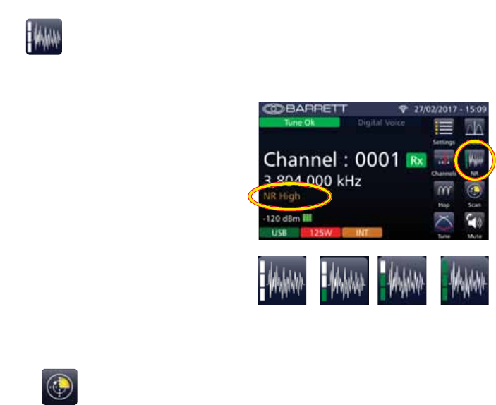
135
BARRETT 4050 HF SDR TRANSCEIVER - OPERATING AND INSTALLATION MANUAL
NR
This option allows the DSP noise reduction depth to be adjusted to suit the
Operator’s comfort requirements.
Tap 15 from the Home screen to
cycle through the options: Off,
Low, Medium, or High.
The example shows an NR set to
High.
After two seconds, the NR indica-
tor is hidden and is replaced by the
channel label.
When the noise reduction system
is active (low, medium or high) the
NR icon displays an indication of
the setting.
NR
Off
NR
Low
NR
Medium
NR
High
Scan
Scanning allows the Transceiver to monitor several channels for incoming calls.
It is particularly useful as the nature of HF signal propagation means that not
all channels are available for communications at one time. For example, a
station calling a station that is in scanning mode can send a Beacon Call on any
channel knowing the station it is calling is monitoring all its available channels.
A response from the scanning station will only occur on channels that are open
for communication.
Stations in scan can also monitor channels for voice activity or signals received
that has a signal strength over a preset level.
The Transceiver will stop scanning for the following reasons:
• Signal Strength Level (SSL) mute is selected and a signal with a level
greater than the pre-set threshold is received.
• Audio (syllabic) mute is selected and a voice signal is detected.
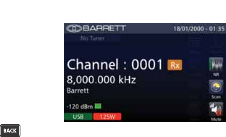
136
BARRETT 4050 HF SDR TRANSCEIVER - OPERATING AND INSTALLATION MANUAL
Tap 6FDQ from the Home screen to
initiate scanning the channels.
Whilst scanning The Rx icon changes
colour from green to orange, several
options on the screen are hidden
(Menu, Channels, Hop, Tune, and
Mode), the Scan icon is animated,
and the keypad’s directional keys are
disabled.
To stop scanning, press .
See page 72 for setting the attri-
butes for scanning.
Selcall Scan
When a Selcall signal is detected, and the channel has Selcall enabled, no mat-
ter which mute type is selected the Transceiver will stop scanning and decode
the Selcall. The Transceiver will only stop scanning when a Selcall is detected.
Signal Strength Scan (SSL Scan)
If the signal strength mute (squelch) is active and a signal with a level greater
than the pre-set threshold is received, the scan will halt. Scan will remain
halted while the signal level stays above the preset threshold. Once the signal
decreases below the pre-set threshold level, for a period greater than the scan
dwell period, scanning will resume.
See page 77 for information on the SSL pre-set threshold and page 73 for
information on the scan dwell period.
Voice (Syllabic) Scan
If the audio mute (squelch) is active and is opened, scanning will halt. Scanning
will remain halted while the audio mute is open. Once the mute closes for a
period greater than the scan dwell period, scanning will resume.
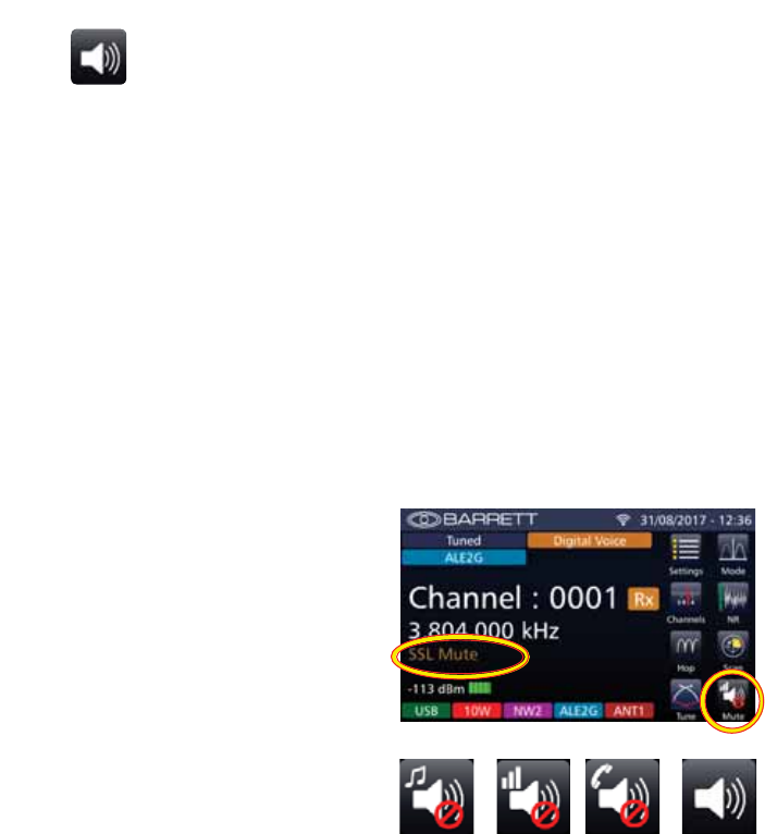
137
BARRETT 4050 HF SDR TRANSCEIVER - OPERATING AND INSTALLATION MANUAL
Mute
Tap Mute from the Home screen to scroll through the options:
Audio Mute Select Audio (syllabic) Mute (squelch) to enable the receiv-
er audio when speech is detected on the selected channel.
Note: The syllabic mute sensitivity can be set to three levels.
See page 77.
SSL Mute Select Signal Strength Level (SSL) Mute (squelch) to enable
the receiver audio when the received signal strength ex-
ceeds the nominated threshold level.
Note: The signal strength mute level can be set to three levels.
See page 77.
Selcall Mute Select Selcall Mute (squelch) to enable the receiver audio
after a Selcall sent to the unit has been received and de-
coded successfully.
Mute Disabled
The example opposite shows SSL
Mute.
After three seconds, the Mute indi-
cator is hidden and replaced by the
channel label.
A further indication of the mute
status is shown in the lower right
hand corner of the Mute icon. A red
circle with a diagonal line indicates
that one of the mute’s status is acti-
vated. The absence of the red circle
indicates that mute is disabled.
Audio
Mute
SSL
Mute
Selcall
Mute
Mute
Disabled
See page 77 for setting the attributes for Mute.
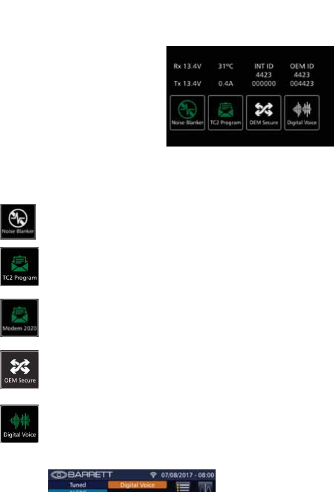
138
BARRETT 4050 HF SDR TRANSCEIVER - OPERATING AND INSTALLATION MANUAL
Swipe Menu
From the Home screen, swipe hori-
zontally from left to right to display
the following screen.
This screen shows various statistical
data for the Transceiver, and if GPS
enabled, displays the GPS coordi-
nates.
From this screen various options may
be set. Tap the following icons to en-
able or disable the options described
below.
When enabled, these icons will illuminate green. If an option is not enabled,
the icons will appear grey.
1RLVH%ODQNHU
Used to reduce interference from vehicles with petrol engines
(see page 94).
TC2 Program
If a TC2 module is installed and TC2 Programming Mode is
enabled, the icon will display TC2 Program. If TC2 Programming
Mode is disabled, the icon will be blank. (See page 58.)
Internal Modem
If a TC2 module is not installed, the TC2 Program icon will be
replaced by the Internal Modem icon. This will toggle between two
internal modems (2020 or 4026).
2(06HFXUH
Enables Voice Encryption (See page 56)
1RWH,IERWKWKH2(06HFXUHDQG'LJLWDO9RLFHRSWLRQVDUHÀWWHG
when one is enabled, the other is automatically disabled.
'LJLWDO9RLFH
Used to increase voice quality and reliable communications.
When transmitting or receiving a call using digital voice, the recipi-
ent’s Transceiver will automatically change to digital voice.
7KHKRPHVFUHHQZLOODOVRFRQÀUPZKHQGLJLWDOYRLFHLVHQDEOHG

139
BARRETT 4050 HF SDR TRANSCEIVER - OPERATING AND INSTALLATION MANUAL
Wireless Application
The Barrett 4050 wireless application supports Windows PCs, iOS and Android
devices for wireless voice and radio control.
Downloading the Barrett SDR Remote Control Head Setup
App
For Windows PCs
Warning: It is essential to install the Bonjour app prior to installing the Barrett Con-
trol Head Installer app.
1. Download the BonjourPSSetup.exe from:
“https://support.apple.com/kb/DL999?viewlocale=en_US&locale=en_US”
Follow the online instructions to install the Bonjour app.
2. Contact support@barrettcommunications.com.au for instructions on
downloading the Barrett SDR Remote Control Head Setup.exe
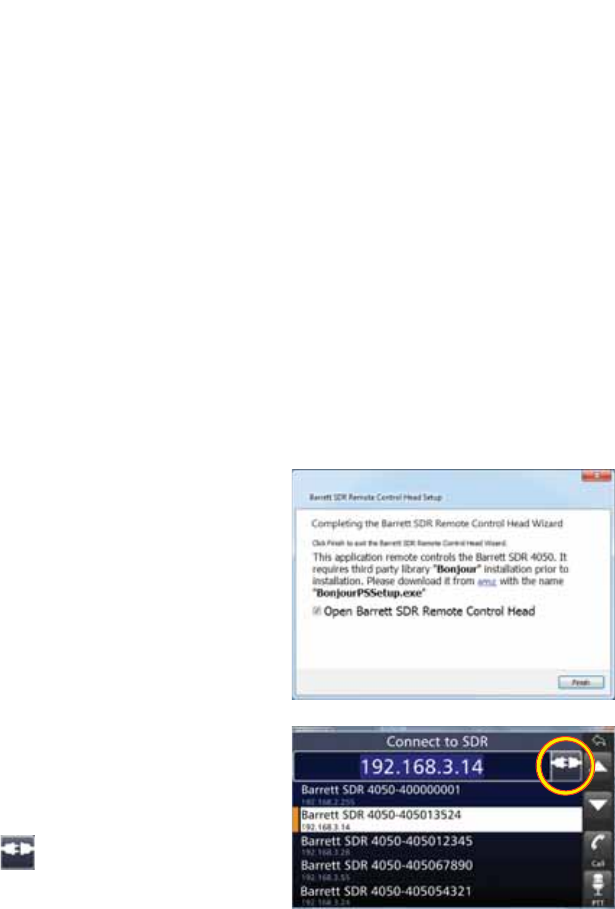
140
BARRETT 4050 HF SDR TRANSCEIVER - OPERATING AND INSTALLATION MANUAL
For iOS and Android Devices
The Barrett SDR Control Head app may be downloaded from:
• The App Store (iOS devices), or
• The Google Play store (Android devices).
Android devices can also download the app directly from the SDR Front
3DQHO7KLVLVSUHIHUDEOHDVWKHÀUPZDUHYHUVLRQRIWKH6'5LVJXDUDQWHHG
to match the app version.
Installing the Barrett SDR Remote Control Head Setup
App
For Windows PCs
Note: Windows 7 is the minimum system requirement for running this app.
3ULRUWRH[HFXWLQJWKH6HWXSÀOH
check whether there is an existing
installation of the app. This must be
XQLQVWDOOHGÀUVW
To install the app, double-click the
Barrett SDR Remote Control Head
6HWXSH[HÀOHDQGIROORZWKHRQOLQH
instructions.
7KHÀQDOLQVWDOODWLRQVFUHHQLVVKRZQ
opposite with a reminder to install
the Bonjour app, (link provided).
Select the 2SHQ%DUUHWW6'55H-
mote Control Head checkbox and
click Finish to display the Connect to
SDR screen.
Select the device to connect to and
tap .
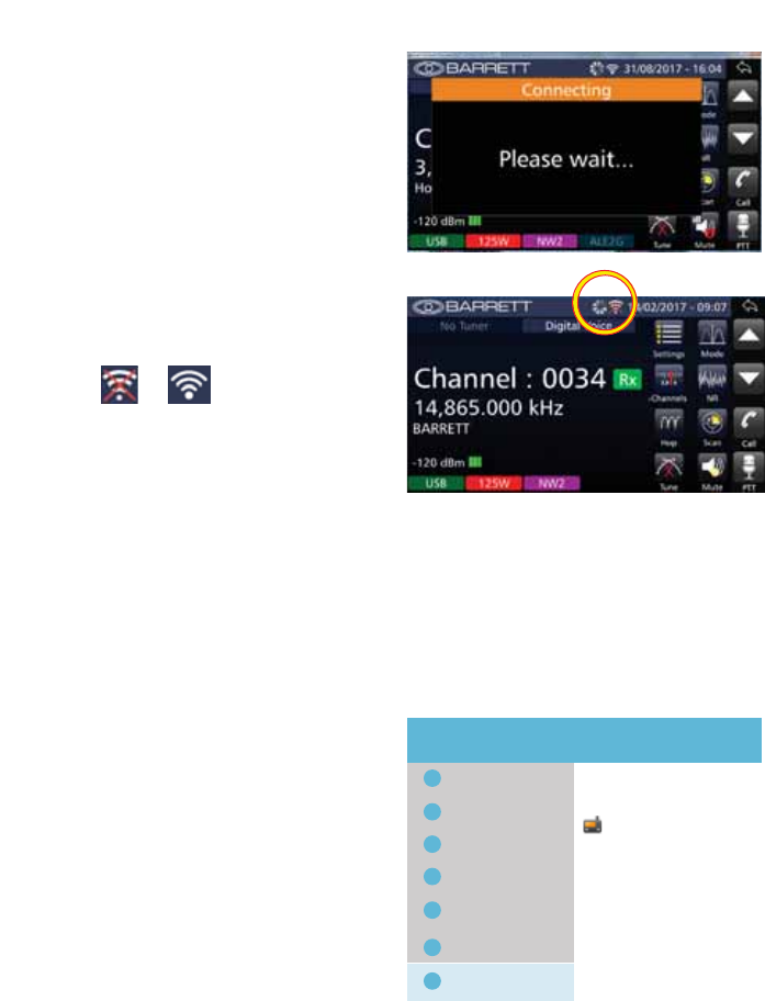
141
BARRETT 4050 HF SDR TRANSCEIVER - OPERATING AND INSTALLATION MANUAL
The Connecting screen displays and
the Busy icon animates as it attempts
to connect the wireless device to the
SDR.
After successfully connecting,
the animating icon disappears and
WKHZLÀFRQQHFWLRQLFRQFKDQJHV
from to .
For iOS and Android Devices
iOS devices can install the app by following the default Apple process after
downloading.
Android devices installing the app from the SDR Front Panel need to follow
these typical procedures.
Check whether there is an existing
installation of the app. This must be
XQLQVWDOOHGÀUVW
To uninstall an application, go to
Settings > Applications
Select the existing installation.
Barrett SDR Control Head App
Wi-Fi
Settings MORE
Search Application Manager
Bluetooth
Flight mode
Data Usage
More Connection Settings
Smart Manager
Applications
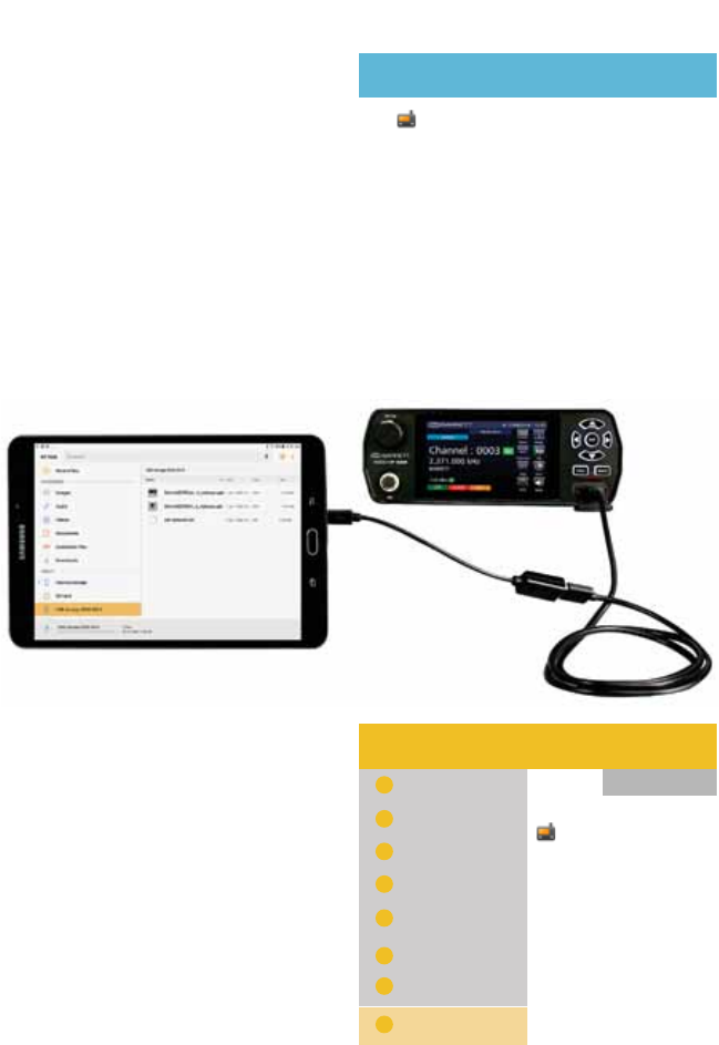
142
BARRETT 4050 HF SDR TRANSCEIVER - OPERATING AND INSTALLATION MANUAL
Tap 8QLQVWDOO to remove the app.
Barrett SDR Control Head App
Application Manager
UNINSTALL FORCE STOP
Storage
Data Usage
Permissions
1RWLÀFDWLRQV
55.92 MB of Internal storage used
81.31 MB used since 30 Sep
Camera, Microphone, and Storage
Connect the device to the SDR ensuring the OTG (On-The-Go) adapter is
connected to the device and not the Transceiver
After the connection is established,
the device’s File Manager displays.
Select:
%DUUHWW6'5&RQWURO+HDGDSN
BarrettSDRControlHead.apk
+
^
USB storage 0000-0073
USB storage...
Recent Files
My Files MORE
Search View As
Device storage
Download history
Documents
Images
Audio
Videos
USB storage 0000-0073

143
BARRETT 4050 HF SDR TRANSCEIVER - OPERATING AND INSTALLATION MANUAL
A warning message displays blocking
the installation.
Tap Settings.
Note: If the CPU architecture of the
Android tablet is “x86” (Intel Inside),
install
“BarrettSDRControlHead-x86.apk”
instead of
“BarrettSDRControlHead.apk”.
Barrett SDR Control Head App
Install blocked
For security, your phone is set to block
installation of apps obtained from
unknown sources.
CANCEL SETTINGS
Select 8QNQRZQ6RXUFHV.
Wi-Fi
Settings Search Lock screen and security
Bluetooth
Flight mode
Data Usage
More Connection Settings
Smart Manager
Applications
Sound
1RWLÀFDWLRQV
Do not disturb
Unknown sources
Encrypt device
Encrypt SD card
Find My Mobile
Info and app shortcuts
1RWLÀFDWLRQVRQORFNVFUHHQ
Screen lock type
Fingerprints
Lock screen
Allow installation of apps from
Protect your device by encrypting
No SD card inserted
Locate and control your device
Security
Show app shortcuts or the device
Show content
Swipe
A warning message displays.
Tap 2..Unknown sources
Allow this installation only
CANCEL OK
¥
Installing from unknown sources may be harmful to
your device and personal data.
By tapping OK, you agree that you are solely responsi-
ble for any damage to your device or loss of data that
may result from using these applications.
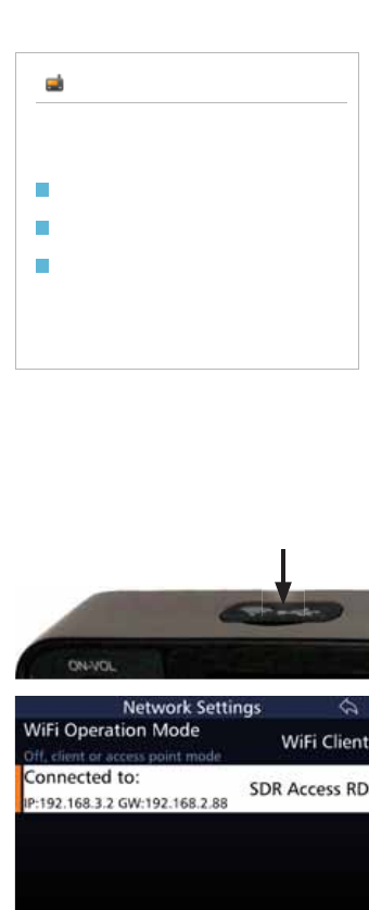
144
BARRETT 4050 HF SDR TRANSCEIVER - OPERATING AND INSTALLATION MANUAL
Tap Install to install the app.
Barrett SDR Control Head App
Do you want to install this application? It will get
access to:
CANCEL INSTALL
take pictures and videos
record audio
modify or delete the contents of your SD card
read the contents of your SD card
Connecting the Wireless Device to the SDR
Preparing the SDR
Prior to invoking the wireless app,
HQVXUHWKHZLÀGRQJOHLVLQVHUWHGLQ
the USB socket located on the top of
the front panel of the SDR.
Also, ensure the SDR’s network
setting’s WiFi Operation mode is set
to enable a connection between the
SDR and the Wireless device.
The example shows the WiFi Oper-
ation mode set to WiFi Client and is
connected to a WiFi network labelled
SDR Access RD.
For further information on WiFi Cli-
ents, refer to the Network section on
page 118.
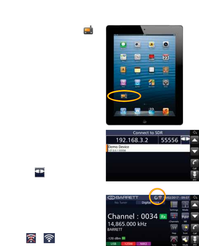
145
BARRETT 4050 HF SDR TRANSCEIVER - OPERATING AND INSTALLATION MANUAL
Invoking the App
To invoke the application, tap
from the wireless device’s App
screen.
A progress bar displays as the pro-
gram loads, followed by a splash
screen and then the Connect to SDR
screen.
Overtype the SDR IP address if neces-
sary (the example shows 192.168.3.2)
then tap to connect the wireless
device to the SDR.
The Busy icon animates as it attempts
to connect the wireless device to the
SDR.
After successfully connecting,
the animating icon disappears and
WKHZLÀFRQQHFWLRQLFRQFKDQJHV
from to .
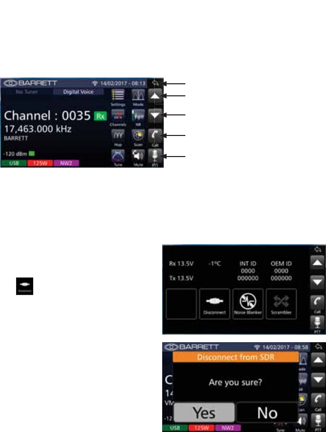
146
BARRETT 4050 HF SDR TRANSCEIVER - OPERATING AND INSTALLATION MANUAL
Exploring the App
The display and icons shown on the wireless device are the same as the front
panel on the 4050 SDR, but includes an additional column of icons replicating
the keypad operations of the 4050 SDR.
Channel up / scroll up
Channel down / scroll down
Clear / back one step
Make a call
Press to talk
The functionality of the Wireless application and the 4050 SDR is essentially the
same.
Disconnecting the Wireless Device from the SDR
From the Home screen, swipe hori-
zontally from left to right to display
the following screen.
Tap .
$FRQÀUPDWLRQVFUHHQGLVSOD\V
Tap Yes.
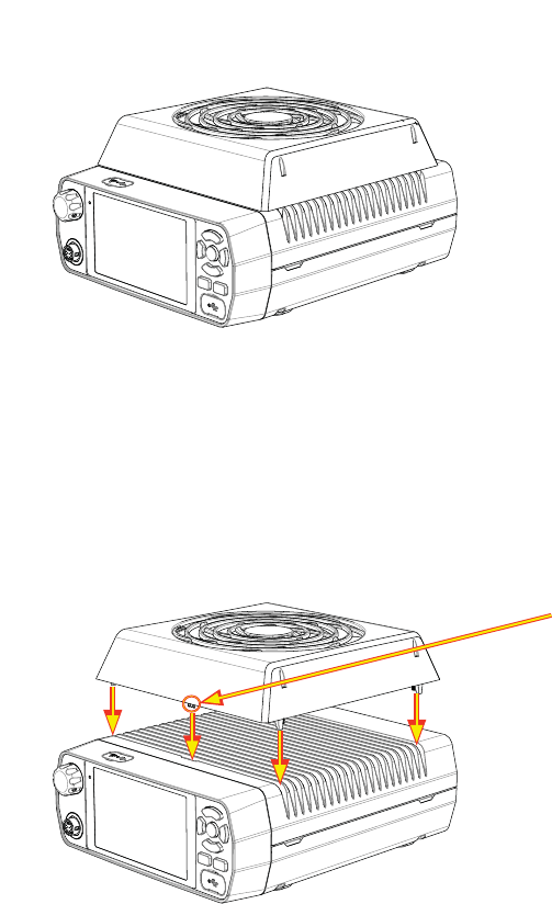
147
BARRETT 4050 HF SDR TRANSCEIVER - OPERATING AND INSTALLATION MANUAL
Cooling Fan
The cooling fan is an optional extra which may be added to the 4050 HF SDR.
The cooling fan requires no user input as it is temperature controlled by soft-
ware, automatically activating when necessary.
Installing the Cooling Fan
Attach the cooling fan to the SDR by carefully aligning the connector pins
located beneath the cooling fan with the socket on top of the SDR as shown
below.
Connector pins
Four screws (located in the four corners of the cooling fan) are used to secure
the cooling fan to the SDR.
To uninstall the cooling fan, simply reverse the installation procedure.
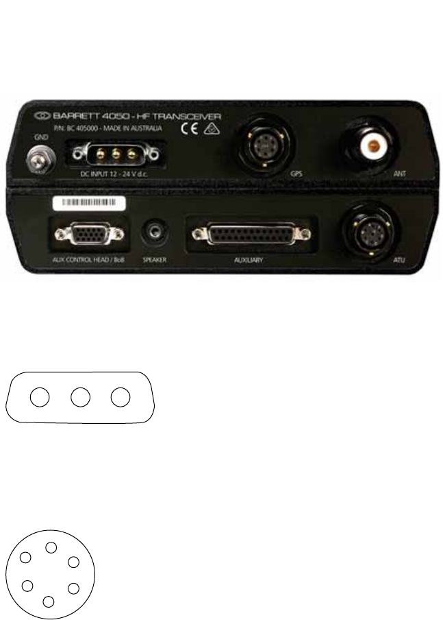
148
BARRETT 4050 HF SDR TRANSCEIVER - OPERATING AND INSTALLATION MANUAL
Connectors
Note: All connectors described below are viewed looking at the rear of the Trans-
ceiver.
Power Connector
A3 A2 A1
A1 12 V DC - 28 V DC
A2 Reserved
A3 Ground
GPS Connector
Signal Level
A
B
CD
E
F
A. 1PPS
B. NMEA+
C. 5 V GPS
D. CW Key
E. GND
F. Reserved
1 Pulse per second
NMEA Data positive
GP Voltage 5 V
Active Low
Ground
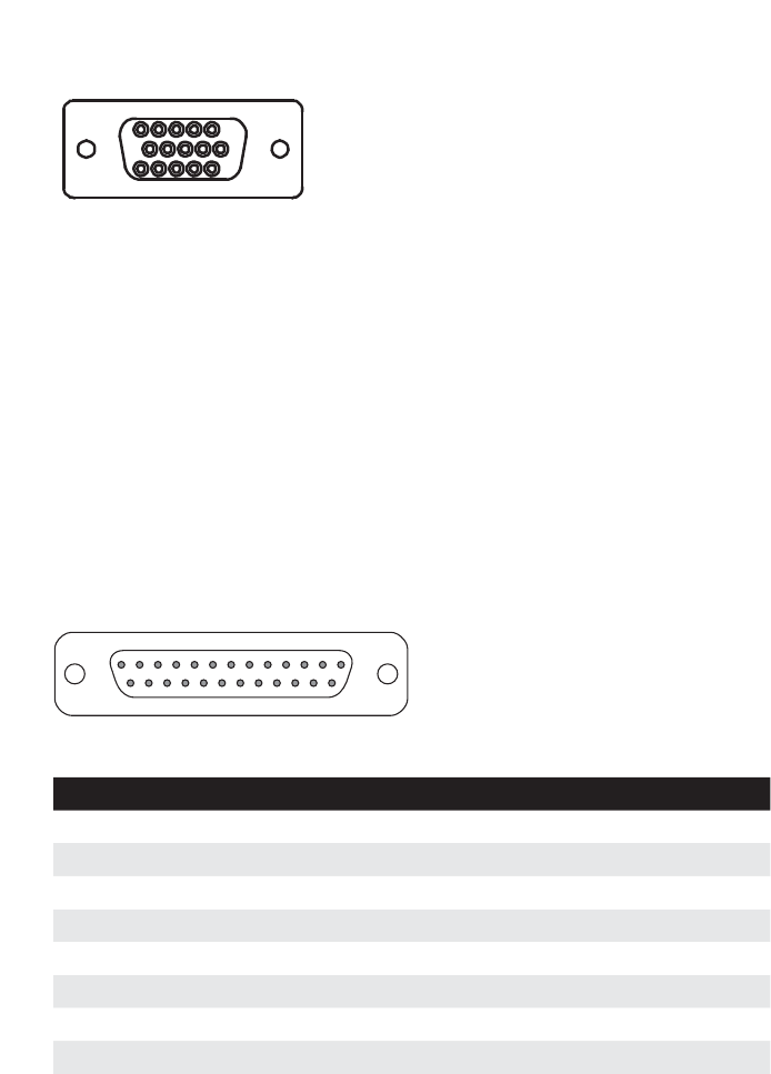
149
BARRETT 4050 HF SDR TRANSCEIVER - OPERATING AND INSTALLATION MANUAL
Aux Control Head / BoB Connector
15
610
1115
1. VCC
2. CAN Bus positive pin
3. CH Audio+
4. Not Connected
5. Ground
6. Ground
7. CAN Bus negative pin
8. CH Audio-
9. Not Connected
10. Line Out
11. Linear amp ALC for Break out Box
12. 13V8 Out
13. Line In+
14. Line In-
15. 1PPS
Auxiliary Connector
1
1425
13
Pin Name Description of Function Level
1 Ground Ground 0 V
2 Rx Data RS-232 data input True RS-232
3 Tx Data RS-232 data output True RS-232
4 Reserved
5 Reserved
6 Reserved
7 RS-232 Gnd RS-232 Ground 0 V
8 ALC In Ext. ALC from Linear Amp 0-10 V

150
BARRETT 4050 HF SDR TRANSCEIVER - OPERATING AND INSTALLATION MANUAL
Pin Name Description of Function Level
9 PTT In Auxiliary PTT input Active low 0 V
10 Aux dig in 1 Scan stop input from exter-
nal modem
Active low 0 V
11 Bal. Tx Audio In Balanced Tx audio input
(with pin 24)
G%PWR
0 dBm
12 Bal. Rx Audio Out Balanced Rx audio output
(with pin 25)
G%PWR
+9 dBm
13 Ground Ground 0 V
14 Reserved
15 Reserved
16 Reserved
17 Reserved
18 Aux dig out 4 Selcall alarm Active low 0 V
19 Aux dig out 5 Audio mute state Active low 0 V
20 Reserved
21 PTT / C-Mute PTT Out / Receiver Cross
Mute
Active low 0 V
22 Reserved
23 +13.8 V Fused Out +13.8 V Output to power
auxiliary equipment
13.8 V @ 2 amp
24 Bal. Tx Audio In Balanced Tx audio input
(with pin 11)
G%PWR
0 dBm
25 Bal. Rx Audio Out Balanced Rx audio output
(with pin 12)
G%PWR
+9 dBm
Note: Balanced Rx audio out on Pin 25 and Pin 12 can be un-muted or follow the
DXGLRPXWHGHSHQGLQJRQWKHFRQÀJXUDWLRQLQWKHSURWHFWHGPHQX,2VHFWLRQ

151
BARRETT 4050 HF SDR TRANSCEIVER - OPERATING AND INSTALLATION MANUAL
ATU Connector
Signal Level
A
B
CD
E
F
G
A. GND and shield
B. RS-232 RX / GPS Data
C. 1PPS
D. Scan
E. Tuned
F. ATU V+
G. RS-232 TX
Ground and cable shield
Receive data line of RS-232
1 Pulse per second
ATU Scan line
ATU Tuned signal
ATU Voltage 13V8
Transmit data line of RS-232
Microphone Connector
Located on the Front Panel.
Signal Level
10
1
2
3
4
5
8
6
9
7
1. MicH
2. MicL
3. GND
4. PTT
5. CH UP
6. CH DN
7. Reserved
8. Reserved
9. SPKR+
10. SPKR-
Microphone audio high
Microphone audio low
Ground
Low going PTT
Channel up
Channel down
Reserved
Reserved
Speaker microphone positive
Speaker microphone negative
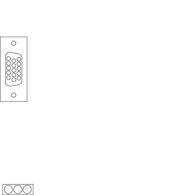
152
BARRETT 4050 HF SDR TRANSCEIVER - OPERATING AND INSTALLATION MANUAL
Control Head Rear Panel Connector
Plug located on the rear of the Front Panel.
5
1
10
6
15
11
1. VCC
2. CAN Bus positive pin
3. CH Audio+
4. SPKR-
5. Ground
6. Ground
7. CAN Bus negative pin
8. CH Audio-
9. SPKR+
10. Head Detect
11. Not Connected
12. Not Connected
13. Not Connected
14. Not Connected
15. Not Connected
Cooling Fan Connector
Socket located on the top of the SDR.
123
(Viewed from the rear of the SDR)
1. Ground
2. + 12 V DC
3. Fan detect

153
BARRETT 4050 HF SDR TRANSCEIVER - OPERATING AND INSTALLATION MANUAL
6SHFLÀFDWLRQV
General
Standards Designed to meet or exceed:
FCC - Part 87 and Part 90
CE#
Australian/ New Zealand standard AS/NZS 4770:2000
and AS/NZS 4582:1999
EMC and vibration standard IEC 945#
MIL-STD 810G for shock , vibration, dust, temperature,
altitude, humidity, and mould.#
NTIA#
JITC#
#
Approval pending
Transmit
frequency range
1.6 MHz to 30 MHz
Receive frequency
range
250 kHz to 30 MHz
Frequency stability ±0.5 ppm (±0.3 ppm optional)
Frequency
resolution
1 Hz tunable receiver
Operating modes J3E (USB, LSB) - H3E (AM) - J2A (CW) - B2B (AFSK) soft-
ZDUHGHÀQHGÀOWHUEDQGZLGWK
Filter bandwidth )XOO\VRIWZDUHGHÀQHG)URP+]WR+]DQG
beyond. Optionally up to 16 kHz
Operating
temperature
-30°C to +70°C relative humidity 95% , non-condensing
Frequency
hopping
25 or 5 hops per second with External Synchronisa-
WLRQ8QLW(68VXSSOLHGZKHQWKHRSWLRQLVÀWWHG7KH
Barrett frequency hopping system requires no master
station, all stations are synchronised and ready to com-
municate on switch on, synchronisation is not effected
by propagation or local interference and there is no late
entry synchronisation delay.
Supply voltage 12 V to 28 V DC operation

154
BARRETT 4050 HF SDR TRANSCEIVER - OPERATING AND INSTALLATION MANUAL
Selcall system Based on CCIR 493-4, four and six digit systems.
Protocol available for free distribution. Fully compatible
with other major HF manufacturers’ four and six digit
systems including encrypted systems
ALE Standards 2G and 3G ALE
Current
consumption
350 mA standby (muted)
Channel capacity Up to 1000 programmable channels (depending on the
4050 variant (simplex or semi-duplex)
Switching speed Less than 15 ms Tx to Rx, Rx to Tx
Weight NJORFDOFRQWUROFRQÀJXUDWLRQ
Width 188 mm
Depth PPORFDOFRQWUROFRQÀJXUDWLRQ
Height 83 mm
Receiver
Sensitivity -121 dBm (0.20 μV) Pre amp off for 10dB SINAD
Selectivity J3E -1 kHz and +4 kHz better than 70dB
-2 kHz and +5 kHz better than 70dB
-5 kHz and +8 kHz better than 70dB
Selectivity J2B
(optional)
-500 Hz and +500 Hz better than 60 dB The level of an un-
wanted signal above the level of a wanted signal that will
reduce the SINAD of the wanted signal from 20 dB SINAD
to 14 dB SINAD
Blocking -20 kHz and +20 kHz better than 71 dB. The level of an
unwanted signal above the level of a wanted signal that
will reduce the SINAD of the wanted signal from by 6 dB
or cause and output level change of 3 dB
Intermodulation Better than 89 dBμV - The level of two unwanted signals,
that are within 30 kHz of the wanted signal, above the
level of a wanted signal that reduces the SINAD of the
wanted signal to 20 dB
Spurious
response ratio
Better than 70 dB

155
BARRETT 4050 HF SDR TRANSCEIVER - OPERATING AND INSTALLATION MANUAL
Reciprocal
mixing
Better than 105 dBμV
In-band IMD Better than 34 dB
Audio output 4 W into 4 ohm at less than 2% distortion
Audio response Less than 6 dB variation from
350 Hz to 2700 Hz
Transmitter
RF output power 150 W PEP Voice (with 24 V supply)
125 W PEP Voice (with 13.8 V supply)
Duty cycle 100% data with fan option
Intermodulation
Products
Better than -31 dB below PEP
(25 dB below two tone peak)
Audio frequency
response
Less than 6 dB variation 350 Hz to 2700 Hz
Current
consumption
Voice average less than 9 amps typical
Two tone less than 12 amps typical
Standby Max 0.5 A
13.8 V DC - Max 21 A (full power 125 W)
24 V DC - Max 15 A (full power 150 W)
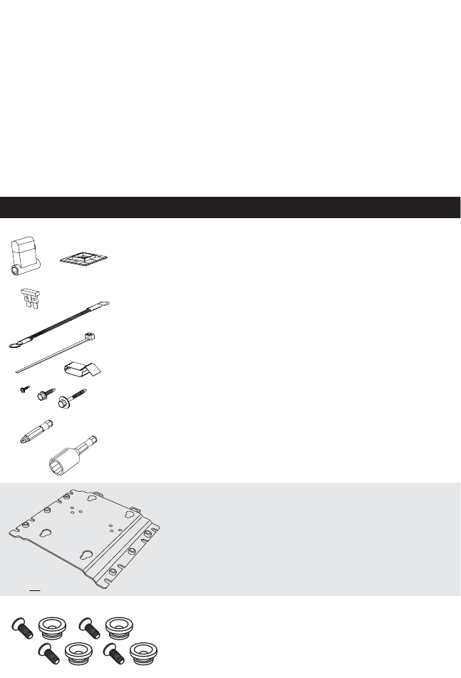
156
BARRETT 4050 HF SDR TRANSCEIVER - OPERATING AND INSTALLATION MANUAL
Installation
This section describes how to change the 4050 Transceiver from a desktop unit
to a remote control (trunk mount) unit using the Mobile Pack P/N BCA40501.
Mobile Pack
(P/N BCA40501)
The mobile pack contains the following components:
Item Description Barrett P/N
Barrett installation kit BCA40004
1
Universal mounting cradle SA-45060
2
Screws and capstans MW-45027
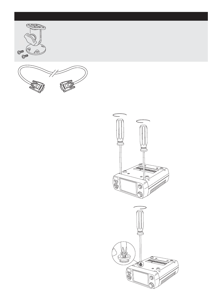
157
BARRETT 4050 HF SDR TRANSCEIVER - OPERATING AND INSTALLATION MANUAL
Item Description Barrett P/N
3RAM mount PW-33334
4
Six metre control head cable
with DE-15 connectors SA-45100
To install the mobile pack, complete the following steps:
1. Invert the SDR and use a
Posidrive #2 screwdriver to
loosen (but not remove), the
two front panel securing screws
located immediately behind the
front panel.
2. Gently pull the front panel from
the SDR to remove it.
3. Fit the supplied capstans to the
four holes as indicated.
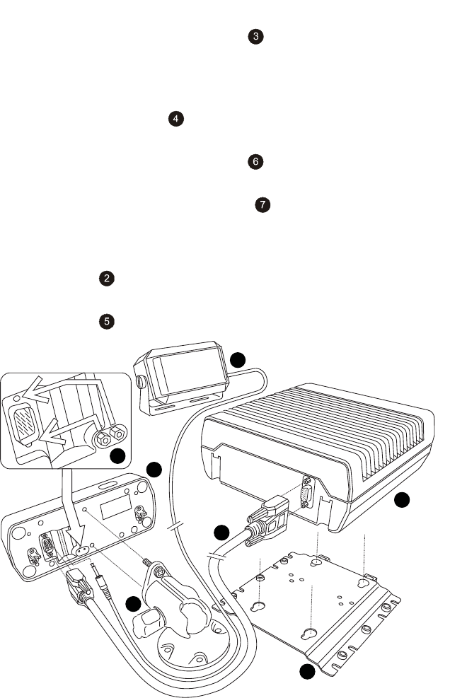
158
BARRETT 4050 HF SDR TRANSCEIVER - OPERATING AND INSTALLATION MANUAL
4. Attach the universal mounting cradle to the desired location using the
À[LQJVSURYLGHG
5. Align the SDR’s capstans into the key holes on the universal mounting cra-
dle and slide to secure it.
6. Attach the RAM mount WRWKHGHVLUHGORFDWLRQDQGDIÀ[WKHIURQW
panel to it using the two screws provided.
7. Plug the six metre control head cable into the socket located at the
front of the SDR and secure using the strain relief screws.
8. Remove the two plug retaining screws from their storage location as
LQGLFDWHGDQGÀWVHFXUHO\LQSRVLWLRQDERYHDQGEHORZWKHFRQWUROKHDG
connector.
CAUTION: Do not over tighten.
9. Plug the other end of the six metre control head cable into the rear of the
front panel and secure using the strain relief screws.
10. Plug the loudspeaker connector into the socket located at the rear of the
front panel as indicated below.
1
5
2
3
4
6
7

159
BARRETT 4050 HF SDR TRANSCEIVER - OPERATING AND INSTALLATION MANUAL
SDR
SDR Front Panel (Control Head)
Universal mounting cradle
RAM mount
Loudspeaker
Six metre control head cable with DE-15 connectors
'HWDLOVIRUÀWWLQJWKHWZRSOXJUHWDLQLQJVFUHZV
Land Based Systems
This section provides instructions for the installation of land based HF commu-
nication equipment.
Most of the installation work can be performed by non-technical personnel if
they carefully follow the instructions given in this manual. However, it is rec-
RPPHQGHGWKDWWKHFRPSOHWHGLQVWDOODWLRQEHFKHFNHGE\DVXLWDEO\TXDOLÀHG
WHFKQLFLDQ,QVRPHHTXLSPHQWFRQÀJXUDWLRQVWHFKQLFDODGMXVWPHQWLVUHTXLUHG
for the equipment to operate correctly.
1RWH6RPHHTXLSPHQWKDVVSHFLÀFLQVWUXFWLRQVVXSSOLHGZLWKLW7KRVHLQVWUXFWLRQV
over-ride the general guidance of this manual, and must be followed in detail.
8QSDFNLQJDQG,QVSHFWLRQ
When unpacking the Transceiver, check the contents against the packing note
provided. Before discarding the carton, check that all accessories have been
removed and are not mislaid in the packing material. Inspect the equipment for
any transit damage. If damage has occurred, notify your supplier immediately.
Failure to do this could affect the warranty covering the equipment.

160
BARRETT 4050 HF SDR TRANSCEIVER - OPERATING AND INSTALLATION MANUAL
Fixed Station Installations
Site Selection Recommendations
The success of every HF Radio system is primarily measured by its ability to
UHFHLYHZHDNVLJQDOVDQGWRWUDQVPLW5)SRZHUHIÀFLHQWO\$QXPEHURILPSRU-
tant factors need to be considered to achieve success. These include: frequency
selection, time of day and ambient noise at the receiver site. Frequency and
time of day are factors which can be used to calculate the maximum usable fre-
quency (MUF) and lowest usable frequency (LUF), for a particular time of day,
using prediction software freely available on the internet. A typical example of
this is VOACAP, http://www.voacap.com/prediction.html
Site selection and system design go hand in hand and should be considered
before any equipment is purchased. Forcing the radio system into an unsuita-
ble site will undoubtedly result in disappointing if not unworkable performance
of the system. Little can be done to improve an installed system if, for example,
the ambient RF noise is unacceptably high.
It is recommended that site evaluation be done before any system designs are
ÀQDOLVHGWRDYRLGV\VWHPSHUIRUPDQFHGLVDSSRLQWPHQW
The following should be considered when choosing a position for the Trans-
ceiver:
Operating
Convenience
The Transceiver should be placed so that the operator is com-
fortable and any required facilities are easily accessible.
Air Circulation 0RVW7UDQVFHLYHUVUHO\RQDLUÁRZDURXQGFRROLQJÀQVWR
dissipate heat generated by the transmitter. The mounting
SRVLWLRQPXVWDOORZIUHHDLUÁRZDURXQGWKHVHÀQV
Proximity of
Transceiver to
Antenna
When using RG-58 coaxial cable from the Transceiver to the
antenna, a cable length of no more than 30 metres is recom-
mended. Should a run of more than 30 metres be required, it
is recommended that a low loss coax such as RG-213 or RG-8
be used.
It is recommended that the Transceiver chassis is connected
to ground using the bolt on the rear panel to stop pick-up
of unwanted noise from local power supplies and electrical
equipment.

161
BARRETT 4050 HF SDR TRANSCEIVER - OPERATING AND INSTALLATION MANUAL
Power Supply
When 12 V DC is supplied to the 4050 Transceiver, the PEP Voice output power
will be restricted to 125 W. Conversely, when 24 V DC is supplied to the 4050
Transceiver, the PEP Voice output power will achieve 150 W.
Power output regulation is done automatically based on the DC voltage pre-
sented to the Transceiver DC input connector. The Barrett 4022 Power Supply is
available in two versions, the BC402200 (12 V DC) and the BC402201 (24 V DC)
version. Each power supply version is capable of operation with AC mains input
voltage between 88 and 256 V AC.
In base station installations where no mains supply is available, various Barrett
VRODUSRZHUVXSSO\YHUVLRQVDUHDYDLODEOHGHSHQGLQJRQWKHV\VWHPFRQÀJXUD-
tion requirement.
1RWH6RPHLQVWDOODWLRQVXVHDQ$&EDWWHU\FKDUJHUWRÁRDWFKDUJHWKHVXSSO\
EDWWHU\%DWWHU\FKDUJHUVFDQSURGXFHHOHFWULFDOQRLVHIURPWKHUHFWLÀHUGLRGHV
This noise causes a static type of interference in the receiver. It may be necessary,
WKHUHIRUHWRVZLWFKRIIWKHEDWWHU\FKDUJHUZKLOVWWKH7UDQVFHLYHULVLQXVH,IÁRDW
charging of batteries is required for installations with unreliable AC power supply,
it is recommended that a Barrett BC402200 or BC402201 be used as each pro-
vides a three stage charge facility to maintain a battery without the noise problem
described above.
Voltage Drop
The average current consumption of the Transceiver is low but during transmis-
sion of voice peaks, high current is needed for short intervals. This means that
the power supply cable must be heavy enough to supply these short duration
current peaks without excessive voltage drop. Preferably, only use the power
cable supplied with the Transceiver. If extra cable is required, use a cable with a
conductor square area of no less than 8 mm2. Unwanted voltage drop will also
occur if incorrect wiring techniques such as poor choice of connection points
and incorrect use of terminal lugs are used.
Protection Fuse
The Transceiver is provided with adequate internal protection. However, the
ÀWWLQJRIDQH[WHUQDOIXVHLVFRQVLGHUHGQHFHVVDU\QRWRQO\IRUSURWHFWLRQRIWKH
7UDQVFHLYHULWVHOIEXWWRHQVXUHWKDWLQWKHHYHQWRIGDPDJHWRWKHFDEOHDÀUH
risk does not exist. The fuse used must be installed in the active wire as close as
possible to the battery, and must be of a type which has a low voltage drop at
the peak currents expected.

162
BARRETT 4050 HF SDR TRANSCEIVER - OPERATING AND INSTALLATION MANUAL
Note: In-line 3AG glass fuses are not suitable. An ATC automotive blade type fuse
rated at 25 A with a suitable high current ATC fuse holder rated at 30 A or more
should be used. These type of fuses and holders are contained in our standard
installation kit (Barrett P/N BCA40004) or are available individually (Barrett P/N
BCA20021).
Antenna
The antenna is a most critical part of the complete radio installation. It must
accept the output power from the transmitter, radiate that power with
minimum loss and in the receive mode, accept weak signals for input to the
receiver.
Incorrect antenna installations will yield poor system performance and are
often the cause of complaints of poor Transceiver performance.
$UDQJHRIDQWHQQDVLVDYDLODEOHIURP%DUUHWWWRVXLWPRVWVPDOOÀ[HGVWDWLRQV
Detailed instructions are included with each antenna.
912 Single Wire Broadband Dipoles
(Barrett P/N BC91201)
Barrett 912 single wire broadband dipoles are ideal for base stations that
require operation on multiple frequencies throughout the HF spectrum using a
single antenna.
7KHDQWHQQDFDQEHPRXQWHGHLWKHULQDKRUL]RQWDORULQYHUWHG¶9·FRQÀJX-
UDWLRQDVLOOXVWUDWHGLQWKHIROORZLQJGLDJUDPV,QWKHKRUL]RQWDOFRQÀJXUDWLRQ
the major radiation direction is broadside to the antenna. When mounted in
WKHLQYHUWHG¶9·FRQÀJXUDWLRQWKHDQWHQQDEHFRPHVIDLUO\2PQLGLUHFWLRQDO
,QWKHKRUL]RQWDOFRQÀJXUDWLRQWKHPLQLPXPGLVWDQFHEHWZHHQWKHPDVWVLV
49 metres and the recommended mast height is 15 metres. In the inverted ‘V’
FRQÀJXUDWLRQWKHUHFRPPHQGHGPDVWKHLJKWLVPHWUHV
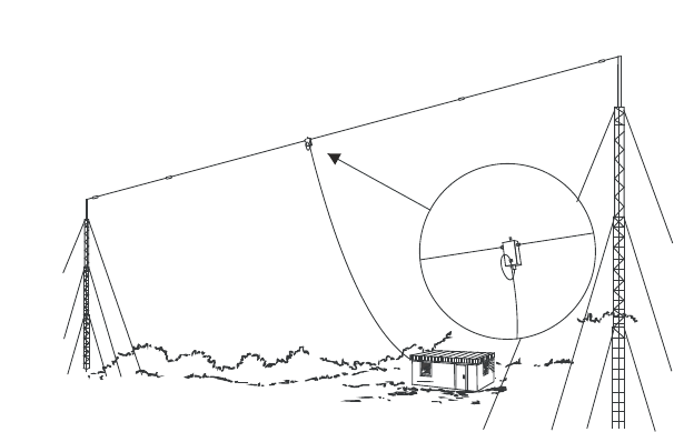
163
BARRETT 4050 HF SDR TRANSCEIVER - OPERATING AND INSTALLATION MANUAL
At this height, the two metre stub masts are each installed at a minimum of 19
metres from the mast base. In locations with limited space, the antenna can
be mounted with the ends past the load resistors drooped down towards the
ground. White nylon supports located just past the load resistors are provided
WRDWWDFKKDO\DUGVIRUWKLVFRQÀJXUDWLRQ,QWKLVFRQÀJXUDWLRQWKHPLQLPXP
distance between masts is reduced to 33 metres. Support towers may be either
lattice masts as illustrated, tubular telomasts or other support structures that
may be available locally. It is recommended that the halyards used to support
the antenna be either UV stabilised Dacron cord or wire rope and that pulleys
should be of stainless steel construction.
,QVWDOOWKHDQWHQQDDVLOOXVWUDWHGLQWKHGLDJUDPVLQWKHLQYHUWHG¶9·FRQÀJXUD-
tion the eye on the top of the balun is used to attach the support halyard.
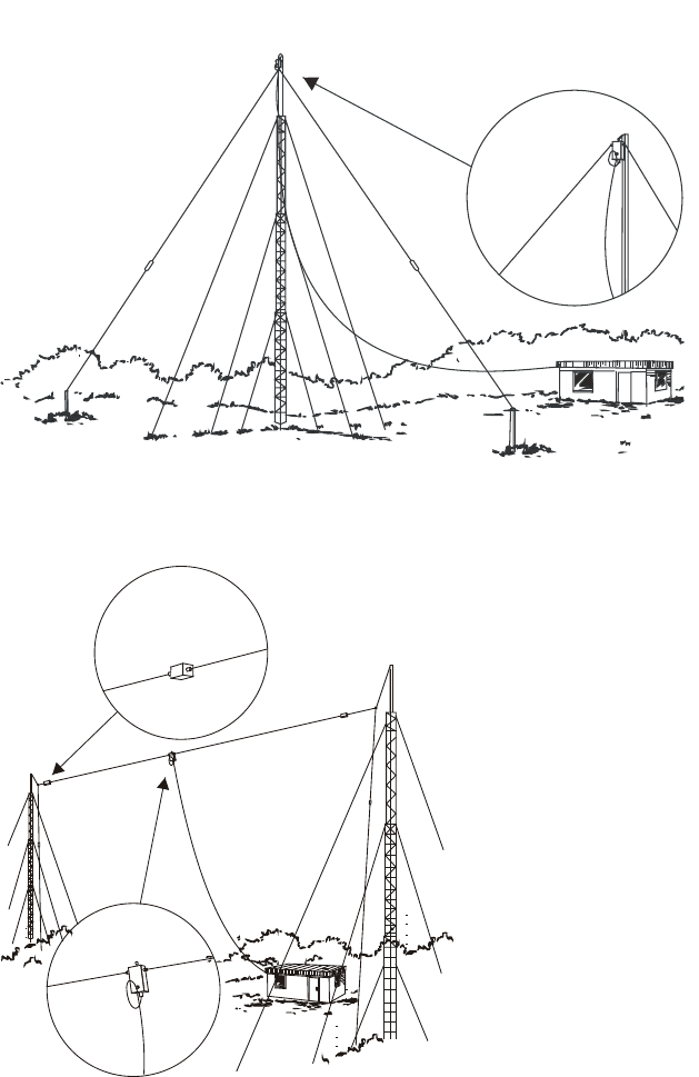
164
BARRETT 4050 HF SDR TRANSCEIVER - OPERATING AND INSTALLATION MANUAL
As with all antenna installations ensure the antenna is as far from sources of
electrical interference as possible and in a position that makes it impossible for
the antenna to come in contact with high voltage overhead mains wiring.
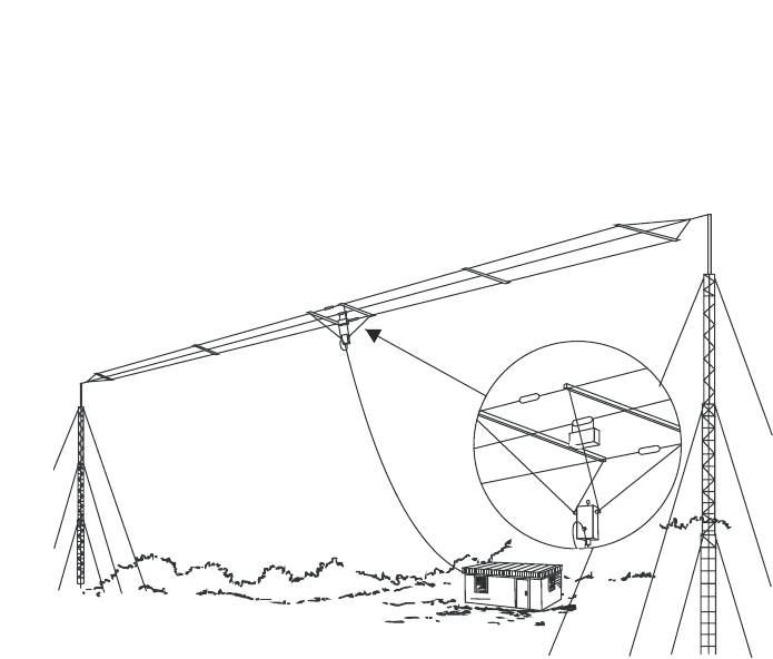
165
BARRETT 4050 HF SDR TRANSCEIVER - OPERATING AND INSTALLATION MANUAL
912 Multi wire Broadband Dipoles
(Barrett P/N BC91200, BC91202 and BC91203)
Barrett 912 broadband dipoles are ideal for base stations that require oper-
ation on multiple frequencies throughout the HF spectrum using a single
antenna.
The Barrett 912 antenna can be mounted either in a horizontal or inverted
¶9·FRQÀJXUDWLRQDVLOOXVWUDWHGLQWKHIROORZLQJGLDJUDPV,QWKHKRUL]RQWDO
FRQÀJXUDWLRQWKHPDMRUUDGLDWLRQGLUHFWLRQLVEURDGVLGHWRWKHDQWHQQD:KHQ
PRXQWHGLQWKHLQYHUWHG¶9·FRQÀJXUDWLRQWKHDQWHQQDEHFRPHVIDLUO\RPQLGL-
UHFWLRQDO,QWKHKRUL]RQWDOFRQÀJXUDWLRQWKHPLQLPXPGLVWDQFHEHWZHHQWKH
masts is 32 metres and the recommended mast height is 15 metres. In the
LQYHUWHG¶9·FRQÀJXUDWLRQWKHUHFRPPHQGHGPDVWKHLJKWLVPHWUHVDQG
at this height the 2 metre stub masts are each installed at a minimum of 19
PHWUHVIURPWKHPDVWEDVH,QWKLVFRQÀJXUDWLRQWKHPDVWPXVWKDYHDQRIIVHW
or out-rigger bracket, at least 0.8 metres long, to hold the antenna away from
the mast. Support towers may be either lattice masts as illustrated, tubular
telomasts or other support structures that may be available locally. It is recom-
mended that the halyards used to support the antenna be either UV stabilised
Dacron cord or wire rope and that pulleys should be of stainless steel construc-
tion.
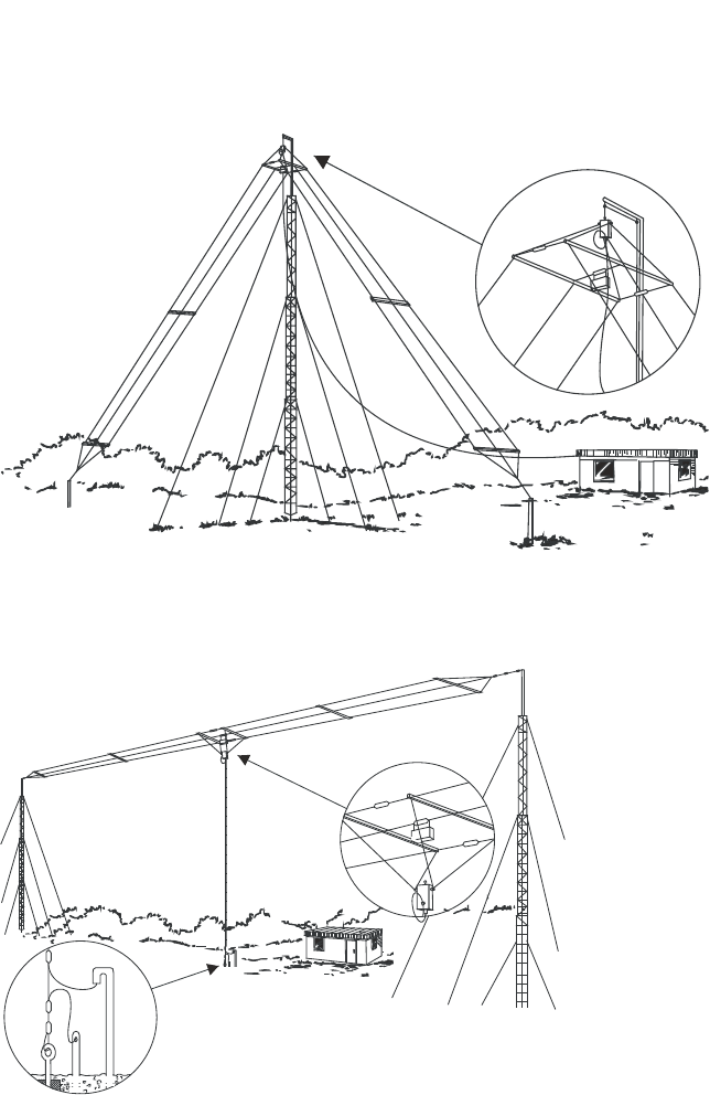
166
BARRETT 4050 HF SDR TRANSCEIVER - OPERATING AND INSTALLATION MANUAL
,QVWDOOWKHDQWHQQDDVLOOXVWUDWHGLQWKHGLDJUDPVLQWKHLQYHUWHG¶9·FRQÀJXUD-
tion the eye on the top of the balun is used to attach the support halyard. In
WKHKRUL]RQWDOFRQÀJXUDWLRQWKHEDOXQKDQJVEHORZWKHDQWHQQD
As with all antenna installations ensure the antenna is as far from sources of
electrical interference as possible and in a position that makes it impossible for
the antenna to come in contact with high voltage overhead mains wiring.
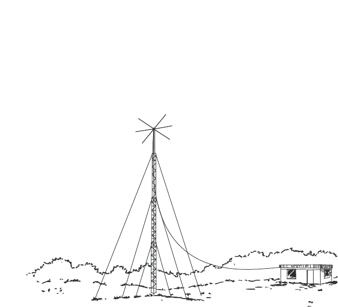
167
BARRETT 4050 HF SDR TRANSCEIVER - OPERATING AND INSTALLATION MANUAL
913 Series Helical Dipoles
(Barrett P/N BC91301 to BC91305)
913 series helical dipole antennas are compact and easily installed, having
extremely narrow bandwidth characteristics and a performance approaching
that of a wire dipole when used at frequencies over 4.5 MHz. The helical dipole
DQWHQQDLVIHGE\DVLQJOHFRD[LDOIHHGHUDQGFDQDFFRPPRGDWHXSWRÀYH
frequencies.
The 913 helical dipole requires a 50 mm diameter mounting pole. This pole
VKRXOGEHORQJHQRXJKWRSODFHWKHKHOLFDOGLSROHDWOHDVWÀYHPHWUHVDERYH
any obstruction. Alternatively, the helical dipole can be mounted on top of a
mast or tower. Make sure that the site selected for the antenna is as far from
any source of electrical interference as possible and that under no circum-
stances can come in contact with high tension power lines.
After mounting the helical dipole hub on the mounting pole, remove the front
circular cover, pass the coaxial cable through the hole at the bottom of the
hub. Screw the UHF connector into the balun. Now screw the helical dipole
elements onto the hub. Each element has its frequency marked on the brass
ferrule used to screw the element onto the hub. Assemble the helical dipole
elements in the positions on the hub as indicated by the diagram enclosed in
the hub. Failure to assemble the helical dipole as indicated in this diagram will
cause tuning problems.
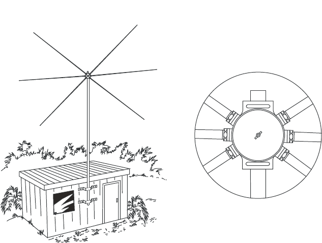
168
BARRETT 4050 HF SDR TRANSCEIVER - OPERATING AND INSTALLATION MANUAL
Hub Detail
+HOLFDOGLSROHVDUHPDQXIDFWXUHGWRVSHFLÀFIUHTXHQFLHVEXWPD\UHTXLUHÀQH
tuning after installation. To enable this, the dipole elements have an adjustable
OHQJWKWLSWRDOORZÀQHWXQLQJIRURSWLPXP96:5GXULQJLQVWDOODWLRQ,QVWDOO
WKHDQWHQQDLQLWVÀQDOSRVLWLRQDQGFKHFNWKH96:5RQHDFKRIWKHIUHTXHQ-
cies that the antenna was manufactured for. Should the VSWR be greater than
1.5:1 the antenna will require adjustment. If a tunable transmitter is available,
determine on each frequency the helical dipole was manufactured for, at what
frequency the best VSWR is obtained. If this occurs at a frequency below the
required frequency then the tips will have to be shortened on the pair of ele-
ments corresponding to that frequency. If the best VSWR occurs on a frequency
higher than the required frequency then the tips will have to be lengthened.
Adjust both ends by an equal amount and repeat the above sequence until
an optimum VSWR is obtained. If a tunable transmitter is not available, use a
method of trial and error to adjust the length of the tips, a little at a time, until
an optimum VSWR is obtained. Remember always adjust each pair of elements
by the same amount at each adjustment.
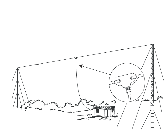
169
BARRETT 4050 HF SDR TRANSCEIVER - OPERATING AND INSTALLATION MANUAL
915 Wire Dipole
(Barrett P/N BC91500)
Single frequency wire dipole antennas, spot-tuned to the required operating
IUHTXHQF\VDUHWKHPRVWHIÀFLHQWDQWHQQDVIRUXVHLQ+)EDVHVWDWLRQV7KH\
are simple to install and have a relatively narrow bandwidth.
Dipole antennas should be mounted at least ½ wavelength from the ground.
Dipoles may be mounted either between two towers or in an inverted “V”
FRQÀJXUDWLRQUHTXLUHVRQO\RQHPDVW$VDJXLGHZKHQLQVWDOOLQJWKHPDVWV
the length between insulators of a half wave wire dipole is 142/(frequency of
dipole in MHz) metres. To this an allowance should be made for extra insulators
and halyards.
For example, a 3.7 MHz dipole - length between the insulators = 142/3.7
=38.38 metres.
:LUHGLSROHVVXSSOLHGE\%DUUHWWDUHSUHFXWWRDVSHFLÀHGIUHTXHQF\EXWKDYH
DGMXVWDEOHHQGV7KHVHDGMXVWDEOHHQGVDOORZÀQHWXQLQJIRURSWLPXP96:5
GXULQJLQVWDOODWLRQ7RÀQHWXQHDGLSROHLQVWDOOWKHDQWHQQDLQLWVÀQDOSRVL-
tion and check the antenna VSWR. Should the VSWR be greater than 5:1 the
antenna will require adjustment.
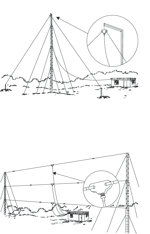
170
BARRETT 4050 HF SDR TRANSCEIVER - OPERATING AND INSTALLATION MANUAL
If a tunable transmitter is available, determine at what frequency the best
VSWR is obtained. If this occurs at a frequency below the required frequency
the dipole is too long, if it occurs on a frequency higher than the required
frequency then the dipole is too short. Drop the dipole and adjust both ends
by an equal amount and repeat the above sequence until an optimum VSWR
is obtained. If a tunable transmitter is not available, use a method of trial and
error shortening or lengthening the dipole ends, a little at a time, until opti-
mum VSWR is obtained. Remember to always adjust each end by the same
amount as the other every time.

171
BARRETT 4050 HF SDR TRANSCEIVER - OPERATING AND INSTALLATION MANUAL
4017 Automatic Tuning Horizontal Dipole Antenna
The Barrett 4017 Automatic tuning horizontal dipole is designed for base
station applications where space is at a premium but high performance is still
required.
Mounting on a standard 50 mm pole, the Barrett Automatic tuning horizon-
tal dipole can be mounted as close as 6 metres from the ground making it
extremely easy to install. With a packed length of only 2.1 metres the antenna
can be easily transported by air.
The tuner has a memory system that stores tuning information for each chan-
nel after an initial tune sequence with unlimited capacity.
$VVHPEO\À[WXUHVDUHVXSSOLHGWRDVVLVWLQPRXQWLQJWKHDQWHQQDWRDQH[LVWLQJ
mast, tower or pole. Alternatively, a range of suitable masts can be supplied
with the antenna.
The Barrett 4017 is supplied standard with a 30 metre composite control, RF
cable and connectors to interface with Barrett 2050 transceivers.
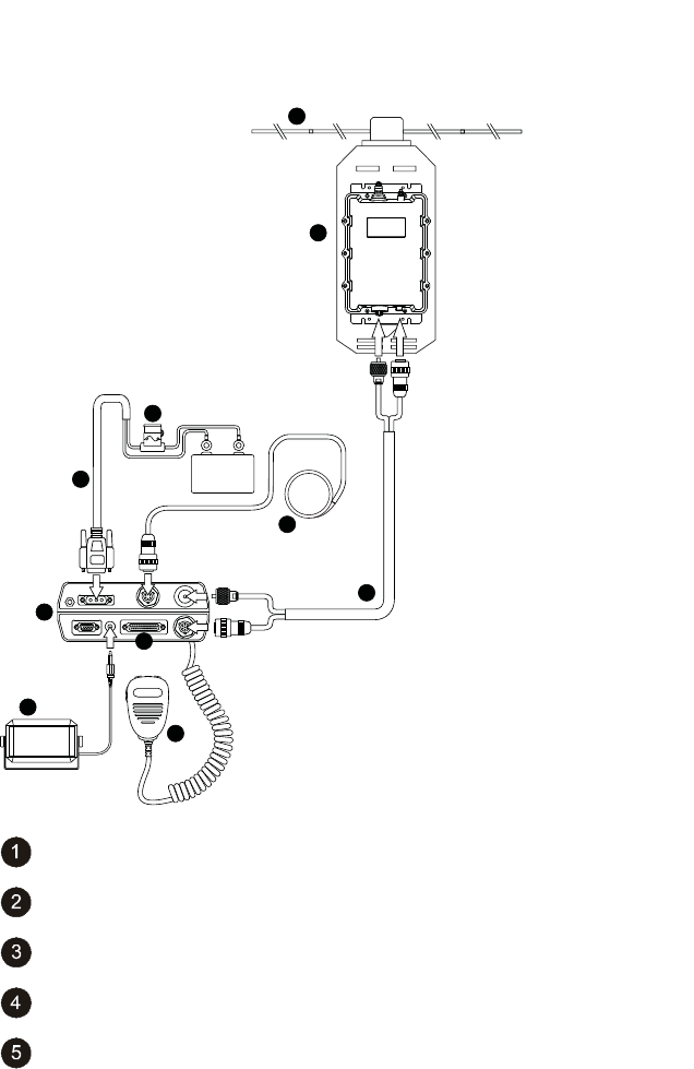
172
BARRETT 4050 HF SDR TRANSCEIVER - OPERATING AND INSTALLATION MANUAL
Connection Details for a 4050 Transceiver and 4017 Automatic Tun-
ing Horizontal Dipole Antenna
+
_
+12 V DC
2
1
9
4
5
10
3
7
8
6
Barrett 4017 Automatic Tuning Horizontal Dipole Antenna
Horizontal Dipoles and Mounting Assembly
Microphone
6 metre power cable supplied with Transceiver
Fuse in-line with spare

173
BARRETT 4050 HF SDR TRANSCEIVER - OPERATING AND INSTALLATION MANUAL
4050 Transceiver
Extension speaker supplied with Transceiver (P/N BCA40015)
External GPS Receiver option (P/N BCA40009)
Auxiliary connector
Coaxial / Control Cable (P/N 4017-01-01)
911 Automatic Antenna Tuner for Base Station Installations
Antenna
9DULRXVDQWHQQDFRQÀJXUDWLRQVVXFKDVYHUWLFDOZKLSVORQJZLUHVDQGORRSV
can be used for base station installations, using the Barrett 911 automatic
antenna tuner. However, the following points should be considered:
The antenna should be mounted as far away as possible from buildings, trees,
vegetation and sources of electrical interference. If metallic masts or supports
are used, arrange insulators to ensure the antenna is spaced at least two
metres from the mast. Remember the radiating part of the antenna starts at
the tuner. The location of the bottom portion of the antenna is very important.
Horizontal wire antennas have maximum radiation broadside to the antenna
when the frequency is less than ¼ wavelength. Radiation is at a minimum at
the end points of the antenna. Inverted “V” installation of horizontal antennas
minimises the directivity and is recommended for omni-directional coverage.
High voltages are present on the antenna system. The antenna tuner and
antenna should be located or protected so that there is no possibility of acci-
dental contact.
Transceiver and Tuner Mounting
The Transceiver should be mounted in a suitable position allowing easy
operator access. The antenna tuner should be mounted, preferably out of the
weather, and as close to the ground (earth) point as possible. The interconnect
cable supplied with the antenna tuner should be routed, away from other
cables, back to the Transceiver and connected as indicated in the diagram. The
maximum interconnect cable should be less than 25 metres.

174
BARRETT 4050 HF SDR TRANSCEIVER - OPERATING AND INSTALLATION MANUAL
Ground (Earth) System
The ground (earth) system is a key part of the overall antenna system and con-
sequently the system operation. An inadequate ground system is the primary
cause of poor performance and tuning problems. There is little point in install-
ing the antenna unless a good ground system can be provided. In areas of
good ground conductivity (i.e. ground always damp), an effective ground can
be made through a grounding rod. This should be approximately three metres
in length and should be installed as close to the tuner as possible. Several rods
bonded together will improve the ground contact. In some cases metal water
pipes may be used as a ground providing:
• The water pipe is close to the tuner and the water pipe enters the ground
close to the tuner.
• There are no joints or couplings in the pipe that will increase the resist-
ance path to ground.
• The water pipe enters soil with good conductivity.
• A low resistance joint is made with the water pipe.
)UHTXHQWO\WKHJURXQGFRQGXFWLYLW\ZLOOQRWEHVXIÀFLHQWWRSURYLGHDVDWLVIDF-
tory ground for the Barrett 911 tuner. This will almost certainly be the case in
well drained sandy soils or on rock. In these cases, a counterpoise must be used
as a ground system. This will also be the case in rooftop installations where no
H[LVWLQJJURXQGSODWHVXFKDVPHWDOURRÀQJH[LVWV
The number of radials required for an effective counterpoise depends on the
soil quality, dampness and other factors which affect the conductivity of the
soil. The more radials used, the better will be the performance of the antenna
/ ATU combination especially at lower frequencies. This manual suggests a
minimum of 20 radials, but optimum performance at low frequencies is not
guaranteed.
The radials of the counterpoise need only be of much thinner cable i.e.
5.48mm2 (#1 #2 SWG) preferably copper wire. RG58 Coaxial cable may be
used. At the base of the antenna, the radials all couple together at a common
well bonded antenna ground point. The radials should be buried into the
ground to a minimum of 200 mm depth.
Note: To accomplish reliable ATU tunes at frequencies below 5 MHz, it is not
uncommon, with poor conductive soil conditions, to require up to 120 radials each
of up to 70 m length, requiring thousands of metres of cable and a lot of trenching.
This is impractical and is the reason we do NOT recommend Whip / ATU antenna
for land based systems.

175
BARRETT 4050 HF SDR TRANSCEIVER - OPERATING AND INSTALLATION MANUAL
Electrical Checkout
After mechanical installation is complete, select the highest frequency to be
used on the Transceiver. A directional watt-meter such as a Bird model 43 may
be inserted in the coaxial transmission line between the Transceiver and the
tuner, although the internal metering of the Barrett 4050 Transceiver is ade-
quate. The tune mode on the Transceiver is then energised. Upon application
of RF energy, the tuner should start to tune, indicated by the ‘clattering’ of
the tuner relays. After a few seconds the relay noise will cease, the Transceiver
should indicate a successful tune and the watt-meter, and front panel indica-
WLRQRIWKHVKRXOGVKRZDORZYDOXHUHÁHFWHGSRZHUFRQVLVWHQWZLWKD
VSWR of better than 2:1. Now select the lowest desired frequency on the Trans-
ceiver and repeat the above procedure. The result should be the same, except
that the tune cycle may take somewhat longer. If the above procedure does not
give the results indicated, check that the antenna length and connections are
correct and re-check all ground (earth) connections.
Note: When received, the Barrett 911 automatic antenna tuner memory system will
usually not have any pre-stored tuning information appropriate to your installation.
To allow the 911 to ‘learn’ its tuning information, simply proceed from one channel
to the next allowing the normal tune cycle to take place. Each successful tune is
‘memorised’ so that when that channel is re-selected the tuner will almost instanta-
neously retune to that frequency.
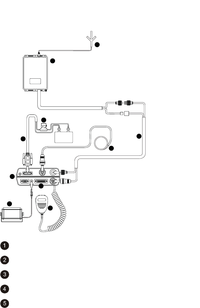
176
BARRETT 4050 HF SDR TRANSCEIVER - OPERATING AND INSTALLATION MANUAL
Connection Details for a 4050 Transceiver and 911 Automatic
$QWHQQD7XQHULQD%DVH6WDWLRQ&RQÀJXUDWLRQ
+
_
+12 V DC
1
6
4
5
10
7
8
9
2
3
7
Barrett 4011 automatic antenna tuner
Antenna
Microphone
6 metre power cable supplied with Transceiver
Fuse in-line with spare

177
BARRETT 4050 HF SDR TRANSCEIVER - OPERATING AND INSTALLATION MANUAL
4050 Transceiver
Extension speaker supplied with Transceiver (P/N BCA40015)
External GPS Receiver option (P/N BCA40009)
Auxiliary connector
Coaxial / Control Cable Extension (P/N BCA90055)
4011 Automatic Antenna Tuner for Base Station Installations
The Barrett 4011 automatic antenna tuner is designed for operation in both
marine mobile and land base station installations.
Housed in a fully weatherproof enclosure the 4011 will tune long wire anten-
nas effectively up to a length of 10 metres and wire loop antennas or whip
antennas over a frequency range of 2 to 30 MHz. Tuning is rapid, typically less
WKDQRQHVHFRQGWKHÀUVWWLPH5)LVDSSOLHGHLWKHUZKLOVWWKHRSHUDWRULVWDONLQJ
or when the “Tune” control is activated on the Transceiver.
7KHWXQHUIHDWXUHVDPHPRU\IDFLOLW\WKDWVWRUHVWKHFRQÀJXUDWLRQ
required to tune to a frequency. On any subsequent use of that frequency, the
UHFRQÀJXUHVWRWKHVWRUHGVHWWLQJVLQW\SLFDOO\OHVVWKDQPLOOLVHFRQGV
)ROORZLQJLQLWLDOWXQLQJWKHDQWHQQDV96:5LVPRQLWRUHG,IDQ\VLJQLÀFDQW
variation occurs, the 4011 will re-tune the antenna automatically.
The 4011 is supplied complete with coaxial / control cable having an overall
length of 30 metres (P/N 4017-01-01). The cable is a composite design incorpo-
rating coaxial, power supply and control cables.
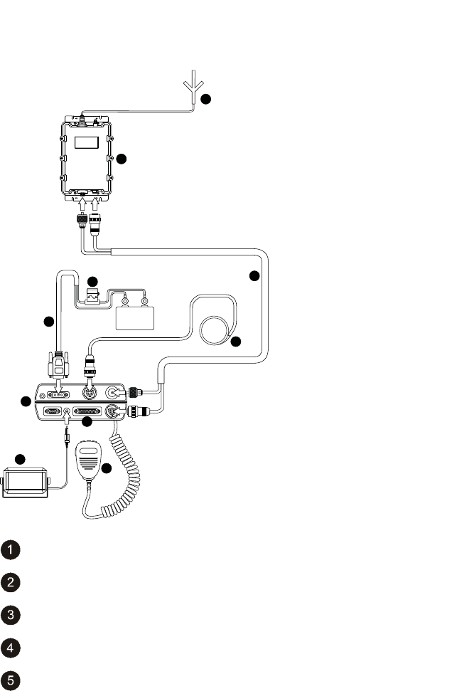
178
BARRETT 4050 HF SDR TRANSCEIVER - OPERATING AND INSTALLATION MANUAL
Connection Details for a 4050 Transceiver and 4011 Automatic
$QWHQQD7XQHULQD%DVH6WDWLRQ&RQÀJXUDWLRQ
+
_
+12 V DC
1
6
4
510
7
7
8
9
2
3
Barrett 4011 automatic antenna tuner
Antenna
Microphone
6 metre power cable supplied with Transceiver
Fuse in-line with spare

179
BARRETT 4050 HF SDR TRANSCEIVER - OPERATING AND INSTALLATION MANUAL
4050 Transceiver
Extension speaker supplied with Transceiver (P/N BCA40015)
External GPS Receiver option (P/N BCA40009)
Auxiliary connector
Coaxial / Control Cable Extension (P/N 4017-01-01)

180
BARRETT 4050 HF SDR TRANSCEIVER - OPERATING AND INSTALLATION MANUAL
Mobile Installations
Site Selection Recommendations
The following points must be considered when mounting the Transceiver.
Safety It is essential that the Transceiver be mounted in a place where
it cannot cause injury to the occupants of the vehicle in the
event of a motor vehicle accident.
For this reason overhead mounting is not generally recom-
mended and “under dash” mounting must take into account
the possibility of injuring the legs of front seat occupants.
Convenience The chosen position for the Transceiver or control head, (if a
remote controlled model is used) should be one which allows
convenient operation.
Positions which are often used are:
• On the transmission hump
• In place of the glove box
• Behind the seat
• Under the dash board (if safe).
Where a remote controlled Transceiver is used, only the control
head need be mounted convenient to the operator. The Trans-
ceiver may be mounted under a seat, in the luggage com-
partment or any other out of the way place within the vehicle
ZKLFKDOORZVIRUVXIÀFLHQWFRROLQJ
All equipment should be positioned in such a way that conve-
nient access for maintenance is provided.
Strength It must be assumed that the vehicle will be used on rough
roads and in many cases off road. Hence mounting of equip-
ment must take into account the severe vibration and shock
that can be expected.
Transceivers may only be mounted to structural components
of the vehicle body and not on dress panels or plastic interior
panels. In some cases, the area around the Transceiver mount-
ing may need reinforcement.
3UHFDXWLRQVVKRXOGEHWDNHQWRHQVXUHÀ[LQJVFUHZVHWFFDQQRW
vibrate loose.

181
BARRETT 4050 HF SDR TRANSCEIVER - OPERATING AND INSTALLATION MANUAL
Air
Circulation
0RVW7UDQVFHLYHUVUHO\RQDLUÁRZDURXQGFRROLQJÀQVWRGLVVL-
pate heat generated by the transmitter. The mounting position
PXVWDOORZIUHHDLUÁRZDURXQGWKHVHÀQV
Obstruction The installation of a Transceiver into a vehicle should not inhibit
WKHQRUPDOXVHRIWKHYHKLFOH%HIRUHÀQDOO\VHOHFWLQJHTXLS-
ment positions, check that normal operation of steering, foot
pedals, gear change, hand brake etc. are not impeded, and that
heater or air-conditioning outlets, glove box and doors are not
obstructed. Always check that the drilling of mounting screw
holes will not damage electrical wiring, heater hoses or hydrau-
lic lines.
Power Wiring
Connect the red positive and black negative wires from the Transceiver power
cable to the positive and negative terminal of the battery. Do not connect to
the ignition switch or internal fuse panels as vehicle wiring to these points is of
LQVXIÀFLHQWFXUUHQWFDSDFLW\FDXVLQJYROWDJHGURSDQGSRVVLEOHQRLVHLQWHUIHU-
ence.
• Route the power cable away from high tension ignition wiring.
• Secure the power cable, either to other wiring or the vehicle body, with
suitable cable ties.
• Where wiring passes through bulkheads, provide appropriate protection
to prevent insulation being damaged.
• ,IDQLVRODWLRQVZLWFKLVÀWWHGEHWZHHQWKHEDWWHU\·VQHJDWLYHWHUPLQDODQG
the vehicle chassis then it is important to connect the radio’s negative
supply cable to the chassis side of the isolation switch.
Earthing
Ideally the radio should be mounted as close as possible to the antenna with
a common earthing point being used for both the antenna’s earth connection
and the radio’s earth connection.

182
BARRETT 4050 HF SDR TRANSCEIVER - OPERATING AND INSTALLATION MANUAL
Antenna
In any radio system an effective antenna installation is essential. Because of the
QHHGWRUHGXFHWKHVL]HRI+)DQWHQQDVVRWKDWWKH\FDQEHÀWWHGWRDYHKLFOH
mobile antenna bandwidth becomes quite narrow and hence tuning is critical.
In most cases the only tuning adjustment that can be effected is adjustment to
position. Particular attention must be given to the antenna position if satisfac-
tory performance is to be obtained. Refer to the instructions supplied with the
antenna you have selected.
Antenna Mounting
The antenna mounting must provide a strong secure anchorage for the base
of the antenna. To obtain maximum radiation, the antenna base must be
well bonded electrically to the vehicle chassis. Paint, dirt, rust, etc. should be
UHPRYHGIURPWKHUHVSHFWLYHÀ[LQJSRLQWV7KHPRXQWLQJSRLQWPXVWSURYLGHD
low resistance electrical path to the main vehicle metallic structure.
Antenna Feed Cables
Antenna feed cables should be run (as far as possible) away from other vehicle
wiring and especially away from ignition high tension wiring. Where passing
through body panels or internal bulkheads, grommets must be used to protect
the cables. Water-proof connectors must be used when they are outside the
vehicle.
Voltage Standing Wave Ratio (VSWR)
After installation it is recommended that the VSWR of the antenna should be
measured for each channel. The instructions supplied with each antenna will
detail this operation.
Noise Suppression
Please note that some newer fuel injected engines emit very strong EMI
(Electromagnetic interference) noise levels across the HF radio band, which is
near impossible to suppress. For these installations, moving the position of the
antenna to another position on the vehicle may reduce the noise effect but full
elimination of noise during engine running may never be achieved. Please note
that this is not unique to the Barrett 4050 radio as all radio makes will suffer
similarly from the effects of this noise under these conditions.

183
BARRETT 4050 HF SDR TRANSCEIVER - OPERATING AND INSTALLATION MANUAL
Noise generated by motor or electrical accessories on the vehicle may cause
objectionable interference to the received signal. This noise enters the receiver
either by means of the battery leads or the antenna system. Providing that the
recommendations concerning battery wiring given earlier in this manual are
IROORZHGQRLVHLQMHFWHGYLDWKHEDWWHU\OHDGLVXQOLNHO\WREHVLJQLÀFDQW0RVW
noise problems result from pick-up by the antenna. Practical cures involve
either preventing the noise from being generated or minimising it from being
radiated by the wiring connected to the noise source.
Interference Suppression Kit
(Barrett P/N BCA20008) is available to assist in noise suppression and contains
ÀOWHUVVXSSUHVVLQJFDSDFLWRUVHDUWKVWUDSVDQGÀWWLQJLQVWUXFWLRQV
The techniques involved in noise suppression include re-routing of wiring,
VFUHHQLQJDQGWKHXVHRIÀOWHUV,WLVDOVRQHFHVVDU\WRPDLQWDLQDOOHOHFWULFDO
equipment in good working order as worn brushes, loose connections and the
like, will increase the amount of noise generated.
Before attempting to cure a noise problem, the source (or sources) of noise
PXVWEHLGHQWLÀHG,GHDOO\WKHUHVKRXOGEHQRGLIIHUHQFHEHWZHHQEDFNJURXQG
noise in the receiver with motor and accessories on and that with motor and
accessories off.
If a detectable difference does exist, turn off all accessories one by one until
a change in noise results. Continue, noting each contributing unit until there
is no detectable difference from the “all off” noise level. (For accessories such
as alternator, motors, instruments etc. a wire or drive belt may have to be
temporarily removed for this assessment.) After identifying each noise source,
they can be worked on one at a time until an acceptable level of suppression is
achieved.
Another approach to this problem is to remove or disconnect all possible
sources of noise then replace and suppress them in turn.
Some suggestions for suppressing particular noise sources follow:

184
BARRETT 4050 HF SDR TRANSCEIVER - OPERATING AND INSTALLATION MANUAL
Ignition Systems All high tension wiring from the ignition coil through to
the spark plugs should be kept as short as practicable,
clean, and as close to the engine block as possible. The
cable should be an impregnated neoprene resistive type
and the coil must be either mounted on, or immediately
adjacent to, the engine block. The low tension wire from
the coil to the distributor contact breaker points must be
as short as possible, and not included with other wires in
a harness or loom. This wire must be shielded if more than
PPORQJ7ZLQÁH[RU¶ÀJXUHHLJKW·FDEOHSURYLGHVD
suitable shield when connected in lieu of the original wire.
This method is useful for shielding other wires suspected
of radiating noise. Do not ignore the wire to an electric
WDFKRPHWHULIRQHLVÀWWHG
Coil to Battery
Wiring
$ORZSDVVÀOWHUVXFKDVWKDWVXSSOLHGLQWKHLQWHUIHUHQFH
VXSSUHVVLRQNLWRUVLPLODUVKRXOGEHÀWWHGDWWKHFRLOHQGRI
WKLVZLUH7KHHDUWKFRQQHFWLRQRIWKHÀOWHUVKRXOGEHVKRUW
and well-bonded to the coil body.
Alternator / Gen-
erator to Battery
Wiring
$ORZSDVVÀOWHUVXFKDVWKDWVXSSOLHGLQWKHLQWHUIHUHQFH
VXSSUHVVLRQNLWRUVLPLODUVKRXOGEHÀWWHGWRWKHPDLQEDW-
WHU\OHDGDWWKHDOWHUQDWRU7KHÀOWHUPXVWEHUDWHGIRUWKH
maximum current available from the charging system. The
HDUWKOXJRIWKHÀOWHUVKRXOGEHDWWDFKHGWRWKHDOWHUQDWRU
body or the engine block.
Alternator
to Regulator
Control Wire
(Generator Field
Wire)
This wire carries switching pulses that often contribute
QRLVHWRWKHUHFHLYHU6XSSUHVVLRQXVLQJFDSDFLWRUVRUÀOWHUV
must not be attempted since damage to the regulator
may result. Separate the wire from all other wiring, keep
it as short as possible and, if longer than about 300 mm it
should be shielded as described above.
Other Regulator
Wires
These are normally adequately suppressed using good
low-inductance bypass capacitors. To be effective, these ca-
pacitors must connect to the wires to be suppressed and to
chassis with very short leads. For this reason, the ‘pigtail’
style of suppressor capacitor often used with MF broadcast
receivers is generally ineffective at HF.
Electric Motors
(windscreen wip-
ers, fans etc.)
Small electric motors can usually be suppressed with good
low inductance bypass capacitors.

185
BARRETT 4050 HF SDR TRANSCEIVER - OPERATING AND INSTALLATION MANUAL
Engine Instru-
mentation
Certain types of oil-pressure sensors and voltage regulators
used in instrument systems contain a vibrating or thermal
cycling contact. These devices can only be suppressed
by isolating and screening or wiring in the same way as
described for the alternator to regulator control wire. Disc
ceramic capacitors with short leads (protected with insulat-
ing sleeving) are frequently useful but to prevent damage
to instrument contacts, where the use of bypass capacitors
is attempted, values larger than 1 nF should not be used.
General Noise Suppression Tips
When searching for sources of noise, some of their characteristics can be help-
IXOLQLGHQWLÀFDWLRQ
• Petrol engine ignition noise and contact breaker noise is a sharp staccato
‘plop’ varying with engine speed. It is only with this class of noise that the
impulse noise limiter incorporated within some Transceivers is effective.
• Noise from other sources generally has a more ‘mushy’ sound. That from
the alternator / generator may only be troublesome over a limited range
RIHQJLQHVSHHGDQGFDQDOVREHLQÁXHQFHGE\WKHVWDWHRIFKDUJHRIWKH
battery.
• The noise from instrument regulators may depend on the battery voltage,
the reading of the instrument and the length of time the system has been
switched on. For this reason, the search for noise sources must be done
thoroughly to prevent noise from apparently reappearing after the instal-
lation has been completed.
• Electric motors generate a ‘whining’ sound. Do not forget to check wind-
screen wipers, electric fuel pumps, heater and air conditioning fans and
other motors which operate only on an intermittent basis.

186
BARRETT 4050 HF SDR TRANSCEIVER - OPERATING AND INSTALLATION MANUAL
2019 Automatic Tuning Mobile HF Antenna
(Barrett P/N BC201900)
The Barrett 2019 automatic tuning mobile HF antenna plugs directly into the
rear of a 4050 Transceiver using the cables supplied.
Important: 4050 Transceivers must have the 2019 antenna option set during pro-
gramming.
Mounting the Barrett 2019 Automatic Tuning Mobile HF Antenna
The Barrett 2019 antenna should be mounted in positions similar to those
illustrated in the diagrams on the following pages. Select a position free from
excessive vibration. A bracket, fabricated to withstand the forces and vibration
that can be expected during off-road driving, should be used to mount the
antenna to the vehicle. When locating the mounting position for the antenna
HQVXUHWKDWWKHDQWHQQDERG\ZKHQÁH[LQJRQLWVYLEUDWLRQPRXQWFDQQRW
come into contact with other parts of the vehicle. The antenna should be
mounted as far from surrounding objects on the vehicle as possible.
The antenna is supplied standard with two sections (Barrett P/N: BCA201901),
a tapered black spring (Barrett P/N: BCA201903), an antenna installation guide
and a pre-terminated six metre control cable to suit the Barrett 2019 antenna
to Transceiver. A six metre (Barrett P/N: BCA201904) or ten metre (Barrett P/N:
BCA201905) extension cable for the control cable is also available.
The control cable should be routed into either the engine compartment or boot
(trunk) of the vehicle. If the joint between the antenna control cable and the
extension cable is in an exposed position, a butyl rubber self amalgamating
tape should be used to seal the joint. Do not wrap this joint if it cannot be
made completely water tight as water will collect in the joint and cause it to
corrode.
$JRRGHDUWKJURXQGWRWKHPDLQERG\RIWKHYHKLFOHLVHVVHQWLDO
IRUHIÀFLHQWRSHUDWLRQRIWKHDQWHQQD To achieve this clean all joints to
bare metal and use copper braid earth straps if any non-metallic joints are
encountered.
After mounting the main body of the antenna, screw the black base spring
onto the antenna body followed by the whip section.
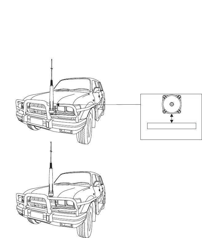
187
BARRETT 4050 HF SDR TRANSCEIVER - OPERATING AND INSTALLATION MANUAL
Important Information
,WLV(66(17,$/WRPDLQWDLQWKHPLQLPXPFOHDUDQFHVEHWZHHQWKH
DQWHQQDDQGVXUURXQGLQJPHWDOZRUNDVLQGLFDWHGLQWKHGLDJUDPV
)$,/85(720$,17$,17+(6(&/($5$1&(6:,//12721/<5('8&(
7+(()),&,(1&<2)7+(%$55(77$8720$7,&781,1*02%,/(+)
$17(11$%870$<$/62/($'72,17(51$/5)$5&,1*$1')$,/85(
,PSRUWDQW
Please note that the mounting of
a 2019 antenna on the front of a
vehicle may be considered illegal
in some areas / countries. Please
check with your local transport /
vehicle authority prior to installa-
tion on the front of your vehicle.
Considerations on the overall
height of the 2019 antenna once
ÀWWHGVKRXOGDOVREHFRQVLGHUHG
ABSOLUTE MINIMUM CLEARANCE
TOP VIEW
160 mm
BULL BAR
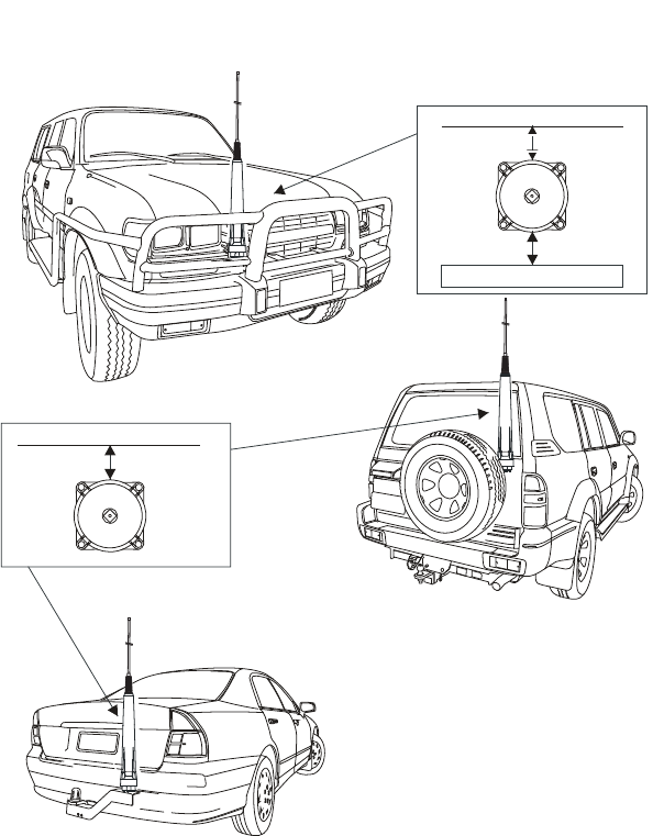
188
BARRETT 4050 HF SDR TRANSCEIVER - OPERATING AND INSTALLATION MANUAL
,PSRUWDQW
Please note that the mounting
of a 2019 antenna on the front
of a vehicle may be considered
illegal in some areas / countries.
Please check with your local
transport / vehicle authority
prior to installation on the front
of your vehicle.
Considerations on the overall
height of the 2019 antenna
RQFHÀWWHGVKRXOGDOVREH
considered.
ABSOLUTE MINIMUM CLEARANCE
TOP VIEW
ABSOLUTE MINIMUM CLEARANCE
TOP VIEW
BONNET
REAR OF VEHICLE
160 mm
160 mm
160 mm
BULL BAR
Caution:- Whilst the 2019 automatic tuning mobile HF antenna is designed to with-
VWDQGYLEUDWLRQWRPLOLWDU\VSHFLÀFDWLRQVRQW\UHGYHKLFOHVVRPHPRXQWLQJSRVLWLRQV
on large prime-movers, particularly front mounted bull bars, are subject to vibration
WKDWIDUH[FHHGVWKLVVSHFLÀFDWLRQ'RQRWPRXQWWKHDQWHQQDLQSRVLWLRQV
such as these as damage to the antenna may result.
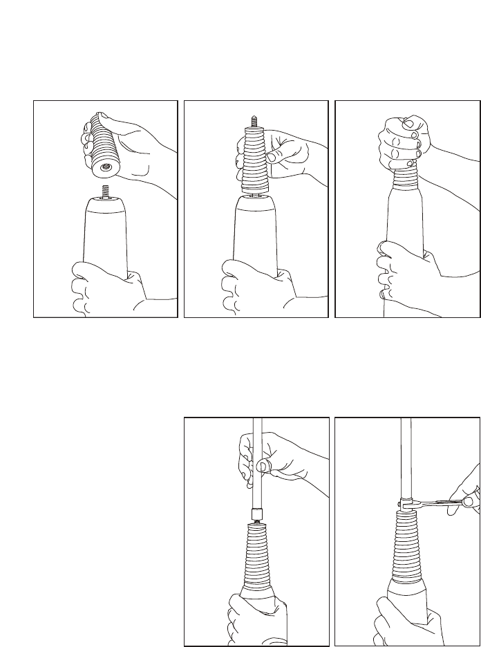
189
BARRETT 4050 HF SDR TRANSCEIVER - OPERATING AND INSTALLATION MANUAL
Antenna Assembly
Mounting the Base Spring
The base spring should only ever be hand tightened, if a tool is used it may
damage the spring base.
Mounting the Whip Sections
To mount the whip
section it is recom-
mended that only one
section of the whip
is screwed onto the
antenna at a time. The
whip section should be
hand tightened fully
then a suitable tool (i.e.
a spanner) can be used
to tighten the section a
further 10 to 20 degrees
clockwise while holding
the antenna body with a
free hand.
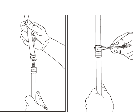
190
BARRETT 4050 HF SDR TRANSCEIVER - OPERATING AND INSTALLATION MANUAL
To mount two whip
sections together,
the unattached whip
section should be hand
tightened fully then
a suitable tool (i.e. a
spanner) can be used
to tighten the section a
further 10 to 20 degrees
clockwise while holding
the already screwed on
whip section with a free
hand.
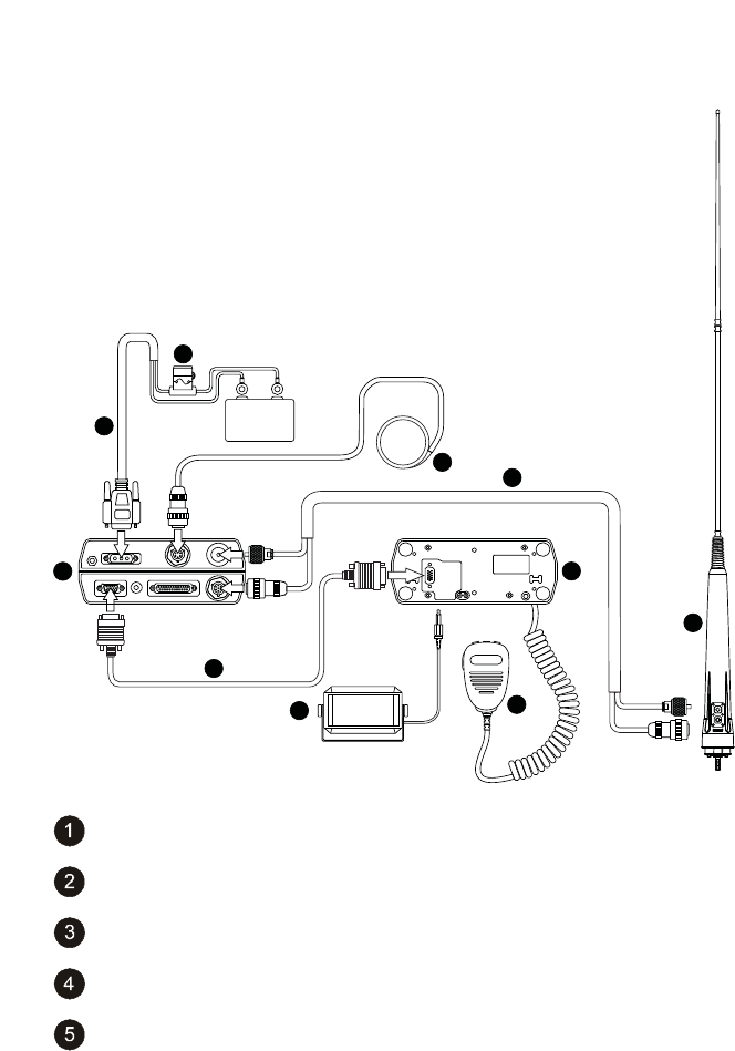
191
BARRETT 4050 HF SDR TRANSCEIVER - OPERATING AND INSTALLATION MANUAL
Connection Details for a 4050 Transceiver with Mobile Pack and
2019 Automatic Tuning Mobile HF Antenna
+
_
+12 V DC
1
2
7
6
5
9
4
8
10
3
Barrett 2019 Automatic Tuning Mobile HF Antenna
4050 control head
6 m Control Cable (P/N SA 45100)
Microphone
Fuse in-line with spare

192
BARRETT 4050 HF SDR TRANSCEIVER - OPERATING AND INSTALLATION MANUAL
6 metre power cable supplied with Transceiver
4050 Transceiver
Extension speaker supplied with 4050 Transceiver (P/N BCA40015)
Coaxial / Control Cable Extension
External GPS Receiver option (P/N BCA40009)
Testing the Barrett 2019 Automatic Tuning Mobile HF Antenna
7RWHVWWKH%DUUHWWDQWHQQDÀUVWVHOHFWWKHORZHVWWUDQVPLWIUHTXHQF\LQ
the Transceiver and tap Tune. The display should show the word “Tuning” for a
IHZVHFRQGVIROORZHGEULHÁ\E\´7XQH3DVVHGµDQGDQLQGLFDWLRQRIWKHPHDV-
ured VSWR (Voltage Standing Wave Ratio) value. Check this reading against the
VSWR meter.
Repeat the above test on the highest frequency in the Transceiver and on a
selection of frequencies in between at approximately 2 MHz intervals. If the
tune passes at all times, the Barrett 2019 antenna is working correctly. The
Barrett 2019 antenna tunes to maximise whip current, not minimise VSWR, but
the displayed VSWR value should generally be between 1.0:1 and 2.0:1. How-
ever, if the display shows “Autotune Fail” accompanied by low pitched beeps at
DQ\SRLQWWKH%DUUHWWDQWHQQDKDVIDLOHGWRWXQH&RQÀUPWKH´$QWHQQD
Type” is selected to “2019 Mobile Ant” in the Transceiver Menu Settings > IO
> Antenna Type setting (page 98). Check all cables are correctly connected,
check the earth cable from the base of the Barrett 2019 antenna has a good
FRQQHFWLRQWRWKHYHKLFOHERG\QRWFKDVVLVRUEDWWHU\FKHFNWKHZKLSÀWWHGLV
not faulty or incorrect and move the vehicle if the Barrett 2019 antenna is close
to any metal fences, buildings etc. If the problem cannot be resolved, contact
your dealer or Barrett Service Department for advice.

193
BARRETT 4050 HF SDR TRANSCEIVER - OPERATING AND INSTALLATION MANUAL
914 Series Manual Tap Whip Antenna
(Barrett P/N BC91401 to BC91424)
Installation
914 series manual tapped whip antennas are mounted on vehicles using
a heavy duty base and spring (Barrett P/N BCA91400). The whip should be
mounted on the vehicle in positions such as those illustrated in the diagrams
below. A bracket, fabricated to withstand the forces and vibration that can
be expected during off-road driving, should be used to mount the antenna
base and spring to the vehicle. When locating the mounting position for the
antenna, the ring located above the label at the bottom of the whip should be
level with the surrounding ground plane, e.g. the bonnet of the vehicle or the
roof of the vehicle. Ensure that the mounting bolt on the base and spring is
electrically bonded to the chassis of the vehicle via a very low resistance path,
i.e. clean all joints to bare metal and use braid earth straps if any non-metal
joints are encountered. Use only good quality coaxial cable and water proof
UHF connectors (such as those supplied by Barrett Communications).
'RQRWXVH3/8+)FRQQHFWRUV.
When running the coaxial cable from the antenna to the Transceiver, avoid
sharp corners and heat such as that generated by the manifold of the engine.
After installing the antenna check the antenna VSWR on each channel. Gener-
ally if the antenna has been mounted in the positions as illustrated, the VSWR
will be less than 1.6-1 and no adjustment is necessary. If the VSWR is not lower
than 2:1 the antenna to ground capacitance in that installation is probably
outside of the design range of the factory set tuning. Consideration may be
given to retuning the whip if the VSWR is so high as to cause the transmitter
ALC system to begin to reduce power (to protect the transmitter).

194
BARRETT 4050 HF SDR TRANSCEIVER - OPERATING AND INSTALLATION MANUAL
For each frequency which will not tune correctly you will need to determine
whether the tuning is high or low in frequency. Generally any frequencies
which will not tune will always be out the same way. When the antenna is
manufactured, most frequencies are deliberately made on the low frequency
side and adjusted upwards by the placement of “tuning rings”. Tuning rings
are single short circuit rings of 20 amp fuse wire placed on the windings of an
individual part of the antenna. A tuning ring inductively raises the frequency of
the section of antenna over which it is placed.
It must be understood that the tuning of an antenna on a particular vehicle
or installation may not hold for other vehicles or installations. To determine
whether any particular frequency tap is high or low, hold the tune key down
on the relevant frequency and observe the VSWR on a suitable meter. Get an
assistant to slowly move his outstretched arm closer to the antenna tap in use.
If the VSWR gets better, then the
antenna is too high in frequency. This
LQGLFDWHVWKDWWKHUHLVLQVXIÀFLHQW
antenna to ground capacity. Usually
this happens when the antenna is
mounted too far away from the body
of a vehicle. Either re-site the antenna
closer to the vehicle or remove any
tuning rings which are already on the
antenna.
If the highest frequency on the whip
requires adjustment, initially place
the tuning ring here and slowly move
upwards until a satisfactory SWR is
obtained.
,IWKHIDFWRU\WXQLQJULQJLVQRWÀWWHG
and the highest frequency on the whip
requires adjustment, initially place
the tuning ring here and move slowly
upward until a satisfactory SWR is
obtained.
If ONLY the lowest frequency requires
adjustment, initially place the tuning
ring here and slowly move upwards
until a satisfactory SWR is obtained.
If the VSWR gets worse when fol-
lowing the above procedure ,then
too much capacity is already present.
This is frequently encountered when
mounting the antenna too low on a
vehicle bumper bar or when mount-
ing close to bodywork as in cab-over
type vehicles. In this case, either re-
site the antenna further away or add
extra tuning rings to the frequency
sections affected until a suitable
VSWR is obtained.
Note: Truck cab-over installations usually produce distorted radiation patterns even
when the VSWR looks good.
When tuning is complete, any new rings added should be coated with epoxy
resin to secure and protect the ring from damage. Five minute quick setting
type epoxy is suitable. If rings need to be removed they may be cut off using a
sharp pair of side cutters. Take care not to cut into the body of the antenna.

195
BARRETT 4050 HF SDR TRANSCEIVER - OPERATING AND INSTALLATION MANUAL
Note: If the wander lead is damaged or lost and requires replacing, the number on
WKHÀUVWWDSLQGLFDWHVWKHOHQJWKRIWKHUHSODFHPHQWZDQGHUOHDGUHTXLUHG
Example: Wl-60 indicates the length of the wander lead was 60cm. When
making a replacement wander lead ensure it is made to this length to obtain
optimum performance.
Operation Instructions
The 914 manual tapped whip antenna should now be screwed into the base
and spring mounted on the front of the vehicle.
The operation frequency being used on the Transceiver should now be selected
on the antenna. This is accomplished with the supplied jumper lead as indi-
cated in the diagram below and the following example (Note: this is an exam-
ple only and your antenna will be manufactured with different frequency taps.)
The 914 manual tapped whip antenna used in the example has the following
frequencies:
Channel 1 4030 kHz Channel 2 4760 kHz The illustration shows a
10 frequency 914 manual
tapped whip antenna
with the highest
frequency being selected.
Channel 3 5190 kHz Channel 4 5254 kHz
Channel 5 7180 kHz Channel 6 8199 kHz
Channel 7 9134 kHz Channel 8 9145 kHz
Channel 9 10567 kHz Channel10 14567 kHz
When using Channel 1, frequency 4030 kHz, the
jumper lead should be removed from the bottom
antenna socket and stored in the vehicle.
On all other channels the jumper lead is required:
For Channel 2, frequency 4760 kHz, the jumper is
plugged into the bottom socket then wound tight-
ly around the antenna and the other end plugged
into the socket marked 4760.
For Channel 3, frequency 5190 kHz, the jumper is
plugged into the bottom socket then wound tight-
ly around the antenna and the other end plugged
into the socket marked 5190.
And so on, to Channel 10.
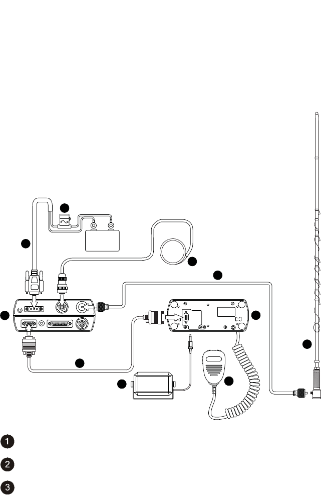
196
BARRETT 4050 HF SDR TRANSCEIVER - OPERATING AND INSTALLATION MANUAL
1RWH,WLVLPSRUWDQWIRUFRUUHFWRSHUDWLRQRIWKHZKLSDQWHQQDWR
KDYHWKHULJKWIUHTXHQF\WDSVHOHFWHGDVLQGLFDWHGDERYHDQGWKDW
the jumper lead is wrapped tightly around the antenna between
VRFNHWV
Connection Details for a 4050 Transceiver with Mobile Pack and
914 Manual Tapped Mobile Antenna
+
_
+12 V DC
1
2
7
6
5
9
4
8
10
3
Barrett 914 Manual tapped whip antenna
4050 control head
6 m control cable (P/N SA 45100)
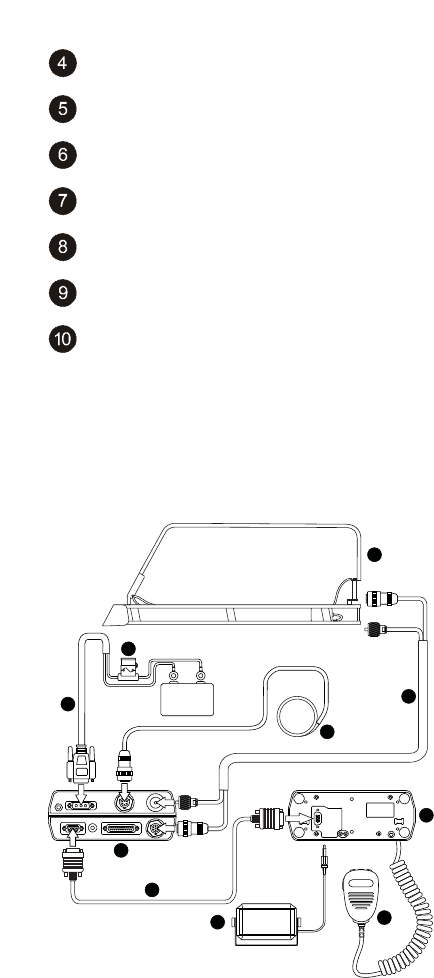
197
BARRETT 4050 HF SDR TRANSCEIVER - OPERATING AND INSTALLATION MANUAL
Microphone
Fuse in-line with spare
6 metre power cable supplied with Transceiver
4050 Transceiver
Extension speaker supplied with 4050 Transceiver (P/N BCA40015)
6 metre control cable (P/N SA 45100)
External GPS Receiver option (P/N BCA40009)
2018 Mobile Magnetic Loop Antenna
Connection Details for a 4050 Transceiver with Mobile Pack and a
2018 Mobile Magnetic Loop Antenna
+
_
+12 V DC
1
2
3
4
5
6
7
8
9
10

198
BARRETT 4050 HF SDR TRANSCEIVER - OPERATING AND INSTALLATION MANUAL
Mobile Magnetic Loop Antenna (P/N BC201801)
4050 Control Head
4050 Transceiver
DC Power Cable (P/N BCA40006)
Fuse in-line with spare
Control & Coaxial Cable 6m (P/N BCA201904)
Microphone (P/N MI-45001)
Loudspeaker (P/N BCA40015)
External GPS Receiver option (P/N BCA40009)
6 m Control Cable (P/N SA 45100)
Marine Installations
The Barrett 911 automatic antenna tuner is designed for use in land base
station and maritime HF services. Primarily designed for operation with end-
fed unbalanced antennas such as whips and long wires, the tuner is built in a
waterproof impact resistant, moulded ABS plastic enclosure.
Antenna Selection
The 911 automatic antenna tuner will operate into almost any end-fed antenna
with a length exceeding 2.5 metres, providing an effective ground (earth) is
XVHG7KHDQWHQQDHIÀFLHQF\ZLOOEHSURSRUWLRQDOWRWKHOHQJWKRIWKHDQWHQQD
and will be maximum when the length of the antenna approaches ¼ wave-
length. It is advisable to limit the wire antenna to ¼ or ¾ wavelength at the
highest frequency to be used.

199
BARRETT 4050 HF SDR TRANSCEIVER - OPERATING AND INSTALLATION MANUAL
Antenna
On sailing vessels the antenna can either be an insulated backstay or a whip
antenna mounted vertically, usually on the stern. Best performance will be
achieved by using an insulated backstay as the radiating length will be longer
than that available when using a whip. The top insulator on the backstay
should be approximately 300 mm from the mast and the bottom insulator
should be at eye level above the deck. The distance between insulators should
be greater than 10 metres and less than 35 metres. A whip antenna is generally
used on small to medium sized power vessels. There are different length whips
to suit the vessel length.
Transceiver and Tuner Mounting
Select a suitable position in the vessel to mount the Transceiver. It should be a
position that is out of the weather and easily accessible to the operator, whilst
as close as practical to the 13.8 V DC power source. Mount the Transceiver to a
VROLGÀ[LQJSRLQWXVLQJWKHPRXQWLQJFUDGOH0DNHVXUHWKHUHLVVXIÀFLHQWVSDFH
at the rear of the Transceiver to connect the power and antenna cables.
The antenna tuner should be mounted as close to the antenna feed point as
possible. In metal vessels the length of the feeder from the antenna tuner to
the feed-through insulator, inside the vessel, should be kept less than 1 metre.
The antenna feed cable should be a suitable high voltage cable. Care should
be taken to avoid sharp points when terminating the cable to prevent corona
discharges.
The interconnect cable supplied with the antenna tuner should be routed away
from other cables back to the Transceiver and connected as indicated in the
diagram overleaf.
Ground (Earth) System
The ground (earth) system is a key part of the overall antenna system and con-
sequently the system operation. An inadequate ground system is the primary
cause of poor performance and tuning problems. There is little point in install-
ing the antenna unless a good ground system can be provided.
Metal hulled vessels provide an almost perfect ground. The tuner ground
terminal should be connected directly to the hull using the shortest possible
ground strap. The point of connection to the hull should be prepared so that it
is free of paint and rust to ensure a good contact area with minimum electrical
resistance.

200
BARRETT 4050 HF SDR TRANSCEIVER - OPERATING AND INSTALLATION MANUAL
:RRGHQRUÀEUHJODVVYHVVHOVSUHVHQWPRUHRIDSUREOHPWRJURXQG,GHDOO\WKH
YHVVHOVKRXOGEHÀWWHGZLWKDQH[WHUQDOFRSSHUJURXQGVKHHWFRQQHFWHGWRWKH
interior of the vessel by suitable stud or an earth plate (“E” plate Barrett P/N
BCA91700)
,IWKHYHVVHOLV\HWWREHFRQVWUXFWHGWKHQLQWKHFDVHRIÀEUHJODVVYHVVHOVDWKLQ
copper sheet with an area of not less than 4 square metres should be moulded
into the hull during lamination. A suitable heavy strap should be connected to
the sheet and left free for earth connection.
Should neither of these methods be available it will be necessary to bond as
many large metallic objects, such as the engine and propeller shaft, together to
form a ground.
Whichever method is used the ground run from the ground system to the
antenna tuner should be as short as possible and use copper strap at least
50 mm wide (wider if available). Consideration must always be given to the
problem of electrolysis. Severe structural damage may occur if electrolysis is
present.
Corrosion
All connections in marine situations are subject to corrosion and oxidation.
To minimise this all joints should be cleaned and have silicon grease applied
before assembly. Under severe conditions joints should be protected with self
vulcanising rubber tape.
Electrical Checkout
After mechanical installation is complete, select the highest frequency to be
used on the Transceiver. A directional watt-meter such as a Bird Model 43
should be inserted in the coaxial transmission line between the Transceiver
and the tuner. The tune mode on the Transceiver is then energised (refer to the
Transceiver user manual). Upon application of RF energy, the tuner should start
to tune, indicated by the ‘clattering’ of the tuner relays. After a few seconds
the relay noise will cease. The Transceiver should indicate a successful tune and
WKHZDWWPHWHUUHÁHFWHGSRZHUVKRXOGLQGLFDWHDORZYDOXHFRQVLVWHQWZLWKD
VSWR of better than 2:1. If the cover of the tuner is removed, the PCB mounted
‘tuned’ LED should be illuminated. Now select the lowest desired frequency on
the Transceiver and repeat the above procedure. The result should be the same,
except that the tune cycle may take longer. If the above procedure does not
give the results as indicated, check that the antenna length and connections
are correct and re-check all ground (earth) connections.
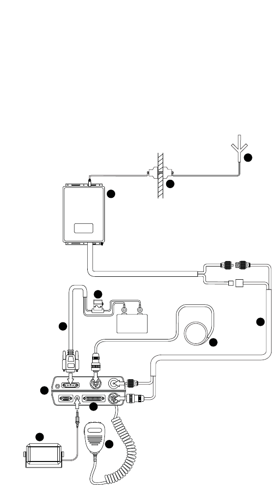
201
BARRETT 4050 HF SDR TRANSCEIVER - OPERATING AND INSTALLATION MANUAL
Note: When received, the Barrett 911 automatic antenna tuner memory system will
usually not have any pre-stored tuning information appropriate to your installation.
To allow the 911 to ‘learn’ its tuning information simply proceed from one channel
to the next allowing the normal tune cycle to take place. Each successful tune is
‘memorised’ so that when that channel is re-selected, the tuner will almost instanta-
neously retune to that frequency.
Connection Details For a 4050 Transceiver and 911 Automatic
Antenna Tuner in a Marine Installation
+
_
+12 V DC
1
6
4
5
10
7
7
8
9
2
3
11

202
BARRETT 4050 HF SDR TRANSCEIVER - OPERATING AND INSTALLATION MANUAL
Barrett 911 automatic antenna tuner
Antenna
Microphone
6 metre power cable supplied with Transceiver
Fuse in-line with spare
4050 Transceiver body
Extension speaker supplied with Transceiver (P/N BCA40015)
External GPS Receiver option (P/N BCA40009)
Auxiliary Connector
Coaxial / Control Cable Extension (P/N BCA90055)
Feed Through Insulator

203
BARRETT 4050 HF SDR TRANSCEIVER - OPERATING AND INSTALLATION MANUAL
Overview of HF Operation
HF (High Frequency) is the radio spectrum with frequencies between 1.6 and
0+]:LWKLQWKLVUDGLRVSHFWUXPDQHIÀFLHQWIRUPRIWUDQVPLWWHUPRGXOD-
tion, SSB (Single Side Band), is used. This, combined with the use of the iono-
sphere - a layer of ionisation gases that resides between 100 and 700 km above
WKHHDUWK·VVXUIDFHSURYLGHVHIÀFLHQWFRVWHIIHFWLYHFRPPXQLFDWLRQVRYHU
short, medium and long distances - without the need for expensive re-transmis-
sion devices, such as the VHF or UHF repeaters or satellites, all of which have
ongoing operational costs and a reliance on a physical infrastructure.
In many remote areas, HF / SSB is the only form of communication possible.
HF Propagation
When HF / SSB radio waves are generated by the Transceiver there are usually
two components:
• The ground-wave, which travels directly from the transmitting antenna to
the receiving antenna following the contours of the earth.
• The sky-wave, which travels upward and at an angle from the antenna,
until it reaches the ionosphere (an ionised layer high above the earth’s
surface), and is then refracted back down to earth, to the receiving
antenna.
Generally speaking, ground-wave is used to communicate over shorter dis-
tances usually less than 50 km. Because ground-wave follows the contours of
the earth, it is affected by the type of terrain it passes over. Ground wave is
rapidly reduced in level when it passes over heavily forested areas or mountain-
ous terrain.
Sky-wave is used to communicate reliably over medium to long distances up to
3,000 km. Whilst the nature of sky-wave propagation means it is not affected
by the type of terrain as in ground-waves, it is affected by factors involving the
ionosphere as described below.
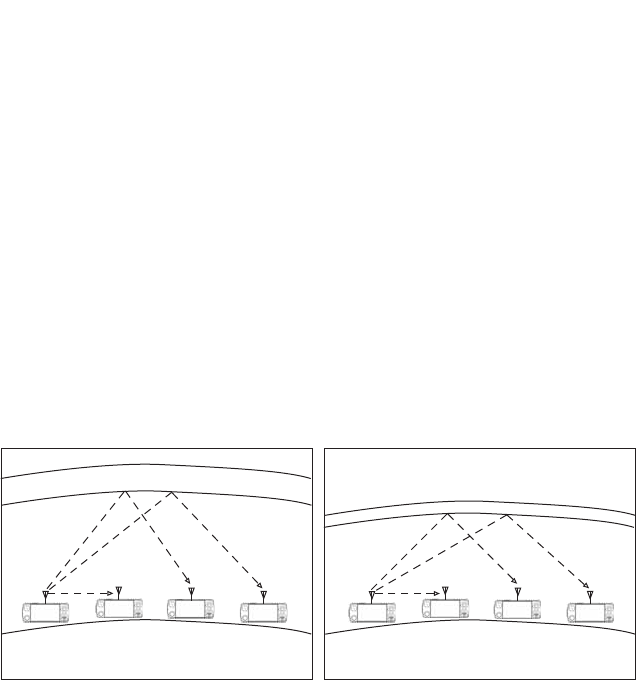
204
BARRETT 4050 HF SDR TRANSCEIVER - OPERATING AND INSTALLATION MANUAL
Radio Wave Propagation
The following illustrations show the characteristics of ground-wave and sky-
wave propagation during day and night time. In each illustration the height of
the ionosphere above the ground is shown.
In both illustrations Station A communicates with Stations B, C and D. Propa-
gation from Station A to B is by ground-wave. The diagrams illustrate that the
ground-wave is not affected by the time of day and the height of the iono-
sphere above the ground.
Propagation from Station A to C and D, is by sky-wave and as the diagrams
LOOXVWUDWHWKHVN\ZDYHLVVLJQLÀFDQWO\DIIHFWHGE\WKHWLPHRIGD\DQGWKH
height of the ionosphere above the ground.
Under each diagram there are recommended working frequencies listed. Please
note that these will vary according to time of year and other factors. They are
intended only as a guide and are subject to change.
'D\ 1LJKW
AB
20 km 800 km 2000 km
EARTH
IONOSPHERE
CDAB
20 km 800 km 2000 km
EARTH
IONOSPHERE
CD
The sun is higher
The ionosphere is higher
The best frequency to use is higher.
A to B - Possible optimum working
frequency is 3 MHz
A to C - Possible optimum working
frequency is between
7 - 9 MHz
A to D - Possible optimum working
frequency is between
13 - 16 MHz
The sun is lower
The ionosphere is lower
The best frequency to use is lower.
A to B - Possible optimum working
frequency is 3 MHz
A to C - Possible optimum working
frequency is between
5 - 7 MHz
A to D - Possible optimum working
frequency is between
9 - 12 MHz

205
BARRETT 4050 HF SDR TRANSCEIVER - OPERATING AND INSTALLATION MANUAL
Factors Which Affect HF / SSB Communications
There are a number of different factors which will affect the success of commu-
nications via HF / SSB radio. These are outlined below:
Frequency Selection
Frequency selection is perhaps the most important factor that will determine
the success of your HF / SSB communications.
Generally speaking the greater the distance over which you want to communi-
cate, the higher the frequency you should use.
Beacon Call, a Selcall (Selective Call) function built into the Barrett Transceiver,
PDNHVÀQGLQJWKHFRUUHFWIUHTXHQF\WRXVHHDV\$%HDFRQ&DOOLVEDVHGRQWKH
Network Transceivers all having a selection of frequencies that will accommo-
date most ionospheric conditions. When in standby, the network Transceivers
scan these frequencies waiting for a call (Selcall or Beacon Call) from another
Transceiver. The Transceiver wishing to check for the best frequency to operate
on sends a Beacon Call to the station to be contacted. If the call to the other
station is successful, a revertive tone from the station being called will be
heard, indicating the channel selected was suitable for the ionospheric condi-
tions prevailing. If the revertive tone is not heard or is very weak, another chan-
nel may be tried until a revertive tone of satisfactory signal strength is heard.
(Refer to Beacon Calls on page 32 for more details.)
Time of Day
As a rule, the higher the sun, the higher the frequency that should be used.
This means that you will generally use a low frequency to communicate early
morning, late afternoon and evening, but you will use a higher frequency
to cover the same distance during times when the sun is high in the sky (for
example, midday). You will need to observe the above rule carefully if your
Transceiver has a limited number of frequencies programmed into it, as you
may only be able to communicate effectively at certain times of the day.
Weather Conditions
Certain weather conditions will also affect HF / SSB communications. Stormy
conditions will increase the background noise as a result of static caused by
lightning. This background noise could rise to a level that will blank out the
signals you are trying to receive.

206
BARRETT 4050 HF SDR TRANSCEIVER - OPERATING AND INSTALLATION MANUAL
Man-made Electrical Interference
Interference of an electrical nature can be caused by overhanging power lines,
high power generators, air-conditioners, thermostats, refrigerators and vehicle
engines, when in close proximity to your antenna. The result of such inter-
ference may cause a continuous or intermittent increase in the level of back-
ground noise.
6\VWHP&RQÀJXUDWLRQDQG,QVWDOODWLRQ
7KHPHWKRGLQZKLFK\RXUV\VWHPLVFRQÀJXUHGDQGLQVWDOOHGZLOODOVRDIIHFW
the success of your HF / SSB communications. Your choice of antenna system
and power supply is critical. Correct installation is also extremely important. An
HF / SSB Transceiver is generally installed using different rules to those used to
install VHF or UHF Transceivers. Failure to correctly install an HF / SSB system
will greatly affect the communications quality you will obtain.
<RXUORFDO%DUUHWWUHSUHVHQWDWLYHZLOOEHDEOHWRDVVLVWZLWK\RXUV\VWHPFRQÀJX-
ration and / or installation.
HF Communications Compared with VHF or UHF Short
Distance Communications
Communications on any HF / SSB Transceiver will sound different to that on
a VHF (Very High Frequency) radio or UHF (Ultra High Frequency) radio or
telephone. This is because of the nature of HF propagation and the modulation
methods used. On HF / SSB Transceivers there will always be background noise
evident behind the signal you are receiving and this will increase when there is
electrical interference or thunderstorm activity in the area.

207
BARRETT 4050 HF SDR TRANSCEIVER - OPERATING AND INSTALLATION MANUAL
Compliance
Barrett 4000 series Transceivers comply to the following communications
standards:
• Australian / New Zealand Standard
• MF and HF Radio Communications.
Equipment in the land mobile service utilising single sideband suppressed
carrier emission:
• AS/NZS 4770:2000
• FCC Part 90.
Barrett 4000 series Transceivers comply to the following EMC standard:
• EN301 489-1 V 1.4.1 (2002-08).
Barrett 4000 series Transceivers comply to the following electrical safety
standard:
• EN60950-1:2002.
FCC RF Exposure Compliance Statement
The Barrett 4000 Series Transceivers have beenFWBMVBUFE and comply
with the Federal Communications Commission (FCC) RF exposure limits
for the General Population/Uncontrolled exposure environment.
In addition, the Transceivers comply with the following standards and guide-
lines:
• FCC 96-326, Guidelines for Evaluating the Environmental Effects of
Radio-Frequency Radiation
• FCC OET Bulletin 65 Edition 01-01 (2001) Supplement C, Evaluating Com-
pliance with FCC
• Guidelines for Human Exposure to Radio Frequency Electromagnetic Fields
• ANSI/IEEE C95.1-1992, IEEE Standard for Safety Levels with Respect to
Human Exposure to Radio Frequency Electromagnetic Fields, 3 kHz to 300
GHz
• ANSI/IEEE C95.3-1992, IEEE Recommended Practice for the Measurement
of Potentially Hazardous Electromagnetic Fields - RF and Microwave.
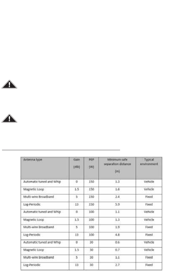
208
BARRETT 4050 HF SDR TRANSCEIVER - OPERATING AND INSTALLATION MANUAL
RF Exposure Warning
To ensure optimal Transceiver performance and to avoid exposure to excessive
HOHFWURPDJQHWLF LHOGV WKH DQWHQQD V\VWHP PXVW EH LQVWDOOHG DFFRUGLQJ WR WKH
instructions provided.
High voltages exist on the antenna during transmission and tuning. Do not touch
the antenna during these activities. RF burns may result.
Install the grounding system or counterpoise as directed to prevent RF burns from
any metal part of the Transceiver.
For IC and FCC compliance, when the 4050 Transceiver is used at a power
level of 10 watts PEPDQGDG%LJDLQDQWHQQD, the antenna(s) used with
this Trans-ceiver should be located at least metres from the operator and
should not be co-located or operating in conjunction with any other
antenna or transmitter.
For IC and FCC compliance, when the 4050 Transceiver is used LQD
YHKLFXODUHQYLURQPHQWat a power level of watts PEPZLWKG%LJDLQ
DQWHQQD, the antenna(s) used with this Trans-ceiver should be located at
least 1. metres from the operator and should not be co-located or
operating in conjunction with any other antenna or transmitter.
7\SLFDODQWHQQDW\SHVDQGPLQLPXPVHSDUDWLRQGLVWDQFH
7KHDERYHDQWHQQDVDUHLGHQWLILHGIRUUHIHUHQFHRQO\,WLVLPSRUWDQWWKDWWKHLQVWDOOHUDQGRSHUDWRU
PDLQWDLQDPLQLPXPVDIHVHSDUDWLRQGLVWDQFHZLWKWKHDFWXDODQWHQQDXVHGLQWKHLQVWDOODWLRQDQG
WRLQVXUHLQDYHKLFXODUHQYLURQPHQWWKDWWKHWUDQVPLWWHULVRQO\XVHGZKHQSHUVRQVRXWVLGHWKH
YHKLFOHDUHDWOHDVWWKHUHFRPPHQGHGODWHUDOGLVWDQFHDZD\
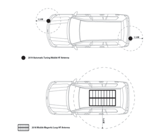
5IFJNBHFCFMPXTIPXTBOFYBNQMFPGNJOJNVNSFDPNNFOEFE
TFQBSBUJPOEJTUBODFGSPNBOUFOOBJOBWFIJDVMBSFOWJSPONFOU
/PUF *GUIFNJOJNVNTBGFEJTUBODFGPSPDDVQBOUTPGUIFWFIJDMF
DBOOPUCFNBJOUBJOFEEVFUPUIFQIZTJDBMMPDBUJPOPGUIFBOUFOOBTJUJT
SFDPNNFOEFEUIBUSFEVDFEUSBOTNJUQPXFS8JTVTFE

BARRETT 4050 HF SDR TRANSCEIVER - OPERATING AND INSTALLATION MANUAL
2
Limited 3 Year Warranty Statement
Barrett Communications Pty Ltd provides a maximum three year warranty on
all equipment it manufactures which is to be used expressly for high frequency,
single sideband radio communications. This warranty covers faults arising from
defects in design, workmanship or materials. Please note that this warranty
does not cover batteries.
Should any fault due to bad design, workmanship or materials be proven
at any time within the warranty period, the company will rectify such fault
free of charge providing the equipment is returned freight paid to Barrett
&RPPXQLFDWLRQV3W\/WGKHDGRIÀFHRUWRDQDXWKRULVHGVHUYLFHFHQWUH7KH
warranty period for all products is thirty six (36) months after date of shipment
from the factory.
In the event that Barrett Communications repairs or replaces a defective
product part under warranty, the repaired or replaced product will remain
covered under and throughout the term of the original warranty period up to
its expiration. No repair or replacement will extend the warranty term past the
original thirty six (36) month anniversary of the original shipment delivery date
of the Barrett Product.
This warranty shall not cover any abuse, accident, improper installation,
connection, adjustment or use other than in accordance with the instructions
issued by the company.
In addition, this warranty shall not cover the distance which transceiver
products will operate over or quality of transmission or reception as a result
of unfavourable environmental conditions. Nor shall this warranty cover the
quality of transmission and reception of transceivers mounted in vehicles or
YHVVHOVWKDWKDYHQRWEHHQVXIÀFLHQWO\HOHFWULFDOO\VXSSUHVVHG
Subject to the matters set out in this warranty, no liability, expressed or implied
is accepted for any consequential loss, damage or injury arising as a result of a
fault in the equipment and, all expressed or implied warranties as to quality or
ÀWQHVVIRUDQ\SXUSRVHDUHKHUHE\H[FOXGHG
This warranty does not extend to products supplied by the company which
are not designed or manufactured by it. Barrett Communications Pty Ltd will
however make every endeavour to ensure that the purchaser receives full
EHQHÀWRQDQ\ZDUUDQW\JLYHQE\WKHRULJLQDOHTXLSPHQWPDQXIDFWXUHU
This warranty is restricted to the original purchaser. Where the original
purchaser is a reseller who has purchased for the purpose of resale, warranty
shall be extended to the reseller’s customer.

BARRETT 4050 HF SDR TRANSCEIVER - OPERATING AND INSTALLATION MANUAL
21
Warranty Registration and Technical Support
Thank you for purchasing Barrett HF communications products.
Please complete the warranty registration form on the next page and send it to
us by mail, fax or email. Please see contact details below.
Once received your contact details will be registered against the serial numbers
of your equipment and Barrett Communications will then be able to contact
you if needed to keep you informed of any developments relating to your
equipment.
If you have access to the Internet you can use the warranty registration page in
the tech support section of our website to register your warranty form. Please
go to www.barrettcommunications.com.au/Support.html
Barrett Communications is proud of its reputation for support of its customers.
This registration process has been introduced so that we may continue to
improve our level of support to you.

BARRETT 4050 HF SDR TRANSCEIVER - OPERATING AND INSTALLATION MANUAL
21
Warranty Registration Contact Details
By Mail The registration forms can be returned by mail, (no postage stamp
required in Australia)
Facsimile 08 9418 6757 (International +618 9418 6757)
Email support@barrettcommunications.com.au
Our customer / dealer technical support department can be contacted via land
mail, email, telephone or with the support department contact form on the
tech support web page.
%DUUHWW&RPPXQLFDWLRQV3W\/WG+HDG2I¿FH
PO Box 1214, Bibra Lake WA 6965 AUSTRALIA
Toll Free Tel: 1800 999 580 (Within Australia)
Tel: +618 9434 1700
Fax: +618 9418 6757
email: support@barrettcommunications.com.au
7HOHSKRQHVXSSRUWIURPWKH$XVWUDOLDQVXSSRUWRIÀFHLVDYDLODEOHIURPDP
to 4:30 pm local time Monday to Friday.
%DUUHWW&RPPXQLFDWLRQV±(XURSH
Unit 9, Fulcrum 2 Victory Park, Solent Way,
Whiteley Hampshire PO15 7FN United Kingdom
Tel: +44 (0) 1489 880 332
Fax: +44 (0) 1489 565 422
email: support@barrettcommunications.co.uk
7HOHSKRQHVXSSRUWIURPWKH8.VXSSRUWRIÀFHLVDYDLODEOHIURPDPWR
5:00 pm local time Monday to Friday.

BARRETT 4050 HF SDR TRANSCEIVER - OPERATING AND INSTALLATION MANUAL
21
Index
A
AGC Hang 95
Alarm Audio Level 87
ALE 100
3G Address 110
3G Alias 70
3G Channels 110
Alias 70
Channel 64
Enable/Disable 113
Save Settings 110
Settings 101
State 102
Antenna
911 Automatic Antenna Tuner 173
Connection Details (Base Station) 176
Connection Details (Marine) 201
912 Multi wire Broadband Dipoles 165
912 Single Wire Broadband Dipoles 162
913 Series Helical Dipoles 167
914 Series Manual Tap Whip 193
Connection Details 196
915 Wire Dipole 169
2018 Mobile Magnetic Loop 197
Connection Details 197
2019 Automatic Tuning Mobile Antenna 186
Assembly 189
Connection Details (Mobile Pack) 191
Mounting 186
4011 Automatic Antenna Tuner for Base
Station 177
Connection Details 178
4017 Automatic Tuning Horizontal Dipole
171
Connection Details 172
Interference Suppression Kit 183
Noise Suppression 182
Socket 64, 75
Type 98
ARINC, Enable/Disable 113
ATU Connector 151
Audio 86
Mute 137
Audio Bandwidth 89
Audio in Tx 78
Audio Level Alarm 87
Audio Record 91
Audio Scrambler 56
Auxiliary Connector 149
B
Backlight Level 116
Backlight Timeout 116
Baud Rate 97
Beacon Call 32
Receive 32
Send 32
Beep Level 87
BER Threshold 107
BITE Test 54
BoB 123
Name 123
Network Settings 124
Network Status 127
Bonjour 139
Broadcast Filter 95
C
Call History 47
Calling Groups 34

BARRETT 4050 HF SDR TRANSCEIVER - OPERATING AND INSTALLATION MANUAL
21
Call Key 31
Call Type 31
Channel 60, 130
Add a Channel 61
ALE Channel 64
Antenna Socket 64
Delete a Channel 66
Edit a Channel 65
Label 59
Mode 63
Number 62
Rx Frequency 62
Save Channel 65
Search a Channel 131
Selcall Format 64
Select Channel 131
Tx Frequency 63
Tx Power 63
Clarify Range 94
Connectors 148
ATU 151
Auxiliary 149
Control Head 149
Control Head Rear Panel 152
GPS 148
Microphone 151
Power 148
Contacts 45, 66
Add 67
Delete Contact 72
Edit Contact 71
Search Contacts 67
Sort Contacts 66
Contacts screen 66
Control Head Connector 149
Control Head Rear Panel Connector 152
Cooling Fan 147
Connector 152
D
Data Link Timeout 108
Date and Time 53
Digital Voice 138
Enable/Disable 113
Display 22, 115
Backlight Level 116
Backlight Timeout 116
Language 54
Timeout Behaviour 116
Dwell Time 73
E
Email Address 70
Emergency Calls 26
Export 114
EXT Alarm Type 97
F
Favourite 46
Add 71
Frequency Hopping, Enable/Disable 113
Front Panel 15
Front Panel Rear View 16
G
*HQHUDO&RQÀJXUDWLRQVVFUHHQ52
General Menu 52
GPS Broadcast 84
GPS Connector 148
GPS Pos 41
GPS Req 40

BARRETT 4050 HF SDR TRANSCEIVER - OPERATING AND INSTALLATION MANUAL
21
Group Calls
Calling Groups 31
Receiving Groups 34
H
Hangup 42
Hop 132
Hopping PIN 55
Hop Rate
Frequency 56
Secure Calls 58
I
,PSRUW&RQÀJXUDWLRQ128
Import / Update 127
Installation 156
Land Based 159
Fixed Station 160
Mobile 180
Marine 198
Interference Suppression Kit 183
International Selcall ID 79
IO 96
K
Keypad 16
L
Labels 59
Label screen 62
Language 54
Last Number Redial 37
Line Audio 90
Line Follows Digital Voice 90
Line In Level 91
Line Out Level 91
Lock 85
Locking the Screen 21
LQA Averaging 105
LQA Decay Rate 105
LQA Exchange 104
LSU Mode 109
M
Menu Map 50
Menus 49
Meter Mode
Receive 117
Transmit 117
Microphone 24
Transmit Timeout 93
Tx Over Beep 53
Up / Down Keys 53
Microphone Connector 151
Mobile Pack 156
Mode 63, 134
Mode screen 63
Mute 137
Attributes 77
Audio 137
Signal Strength Level 77, 137
Syllabic Sensitivity 77, 137
N
Network 118
Network Selcall ID screen 79
Selcall Networks 81
Noise Blanker 94, 138
Noise Suppression 182
NR 135
O
OEM 1 Calls 30

BARRETT 4050 HF SDR TRANSCEIVER - OPERATING AND INSTALLATION MANUAL
21
OEM Privacy Key 80
OEM Secure Key 56
OEM Secure Type 56
OEM Selcall ID 80
Option PINs 113
P
Pagecall 38
Receive 39
Send 38
Power Connector 148
Preamable Time 79
Preselector 95
Preset Map 102
Program Firmware 129
Programming 25
R
Rear Panel 17
Receive Meter Mode 117
Response Control 103
Resume Time 73
Resync 21
RF 92
Ring Tones 88
RS232 Baud Rate 97
RS232 Out 96
5[&RQÀJXUDWLRQ88
Rx Preamp 92
S
Scan 72, 135
Rate 72
Selcall Scan 136
Signal Strength Scan 136
Voice (Syllabic) Scan 136
Scan Table 73
Add 74
Antenna Type 75
Channel List 75
Delete 76
Edit 74, 76
Name 75
Save 76
Select 73
SDR Name 52
SDR Serial Number 114
Secure Call 44
Enable/Disable 113
Hop Rate 58
Secure Call Codes 58
Secure Data Key 57
Secure Digital Voice Key 57
Security 55
Selcall 29, 33, 78
Format 82
ID 4 Digit 82
6 Digit 83
International Selcall ID 79
OEM Selcall ID 80
Networks 81
Add 81
Alias 82
Delete 84
Edit 83
Save 83
Receive 33
Selcall Screen 78
Send 33
Selcall Format 64

BARRETT 4050 HF SDR TRANSCEIVER - OPERATING AND INSTALLATION MANUAL
21
Selcall Format screen 64
Self IDs 29
Serial Number 114
Settings Menu 49
Settings screen 49
Signal Strength Level 77
SINAD Threshold 106
Software Version Information screen 112
Sounding Address 104
Sounding Control 103
6SHFLÀFDWLRQV153
General 153
Receiver 154
Transmitter 155
Squelch 77
SSL 77
Station ID Ranges 30
Status Call 43
Swipe Menu 138
Syllabic Sensitivity 77
System Info 111
System Status 111
T
TC2 Programming Mode 58
Telcall 29, 35
Receive 37
Send 35
Temperature Units 117
Threshold Test 106
Transceiver 15
Front Panel 15
Front Panel Rear View 16
Keypad 16
Rear Panel 17
Switching On / Off 18
Transceiver Lock 85
Transceiver Name 52
Transceiver Options 113
Transmit Meter Mode 117
Tune 134
7[&RQÀJXUDWLRQ89
Tx Over Beep 93
Tx Power 63
Tx Power Level 94
Tx Power screen 63
U
Unlocking the Screen 21
V
Version Information 112
Voice Link Timeout 108
Voice Security, Enable/Disable 113
Volume 19
VSWR 134
W
WiFi
Access Point Mode 120
Access Point Setup 120
Client 118
Enable/Disable 113
Operation Mode 118
Wireless Application 139
Barrett Communications Pty Ltd
47 Discovery Drive, Bibra Lake, WA 6163 Australia
Tel: +61 8 9434 1700 Fax: +61 8 9418 6757
Email: information@barrettcommunications.com.au
www.barrettcommunications.com.au