Baumer Ident OIS-P3100 Identification System User Manual B1030203 p65
Baumer Ident GmbH Identification System B1030203 p65
Manual
OIS-P
OIS-P PC 3100/01 series
8 kbyte Communicators PC3141/03
System Description and Installation Manual
B 1030 200
Page intentionally blank.

Reg. No. B1030 200
Edition 4
May 2001
Subject to alteration without prior notice.
Baumer Ident GmbH, Hertzstrasse 10, D-69469 Weinheim
© Copyright Baumer Ident GmbH 2001 Tel +49 6201 9957-0 Fax +49 6201 9957-99
Printed in Germany.
3

4 Baumer Ident OIS-P, PC3141/03 Manual
Page intentionally blank.

OIS-P, PC3141/03 Manual Baumer Ident 5
The products described in this document may be subject to modifications without corresponding updating of the document.
© Copyright 2001 Baumer Ident GmbH. Printed in Germany.
This product contains parts, that are
sensitive against electrostatic
discharges. Please heed the
particular instructions for protection.
Ground yourself before you touch the
appliance.
FCC ID: PNTOIS-P3100
The device complies with part 15 of the
FCC rules. Operation is subject to the
following two conditions:
(1) this device may not cause harmful
interference, and (2) this device must
accept any interference received,
including interference that may cause

6 Baumer Ident OIS-P, PC3141/03 Manual
Page intentionally blank.

OIS-P, PC3141/03 Manual Baumer Ident 7
Contents
Contents
1 System description ............................................................................. 9
1.1 General ........................................................................................ 9
1.2 System components ..................................................................... 9
1.3 Mechanical description ................................................................. 9
1.4 EUROX_4-Software ................................................................... 10
1. 4.1 General............................................................................ 10
1.4.2 Commands ....................................................................... 10
2 System performance ........................................................................ 13
2.1 Communication speed ................................................................ 13
2.1.1 Data Tag communication .................................................. 13
2.1.2 Host communication times ................................................ 14
2.1.3 Total communication time .................................................. 15
2.2 Communication area ................................................................... 16
2.3 Distance between Data Tags ..................................................... 17
2.4 Distance between antennas ....................................................... 18
3 Environmental influence .................................................................. 19
3.1 General ...................................................................................... 19
3.2 Metallic objects ........................................................................... 20
3.3 Foreign substances between antenna and Data Tag ................. 21
3.4 Temperature ............................................................................... 21
3.5 Electromagnetic immunity .......................................................... 21
3.6. Conclusions on environmental influence .................................... 22
4 Health aspects .................................................................................. 23
4.1 Emitted power levels .................................................................. 23
4.2 Health and safety cautions ......................................................... 23
5 Maintenance aspects ....................................................................... 25
5.1 General ...................................................................................... 25
5.2 Battery life .................................................................................. 25
6 Installation ........................................................................................ 27
6.1 Mechanical installation ............................................................... 27
6.2 Electrical connection .................................................................. 28
6.2.1 Power supply and object detect ......................................... 28
6.2.2 Serial communication ........................................................ 28
6.2.3 Antenna connection ........................................................... 30
6.2.4 Test terminal ..................................................................... 30
7 Installation and trouble-shooting ................................................... 31
7.1 Communicator Set-Up ................................................................ 31
7.2 Test methods and error codes .................................................... 33
7.3 PC program for communication test ........................................... 34
7.4 Built-in communication reliability statistics .................................. 34

8 Baumer Ident OIS-P, PC3141/03 Manual
Contents
7.5 Internal inspections and tests ..................................................... 35
7.5.1 General ............................................................................. 35
7.5.2 Connector Board and fuse ................................................ 35
7.5.3 LED indications ................................................................. 35
7.5.4 Power Board ...................................................................... 36
7.5.5 CPU Board ........................................................................ 37
8 Technical Data .................................................................................. 39
8.1 Communication parameters ........................................................ 39
8.2 Mechanical specification ............................................................. 39
8.3 Electrical specification ................................................................ 39
8.4 Cable specifications .................................................................... 40
8.5 Environmental specification ......................................................... 41

OIS-P, PC3141/03 Manual Baumer Ident 9
System description
1.1 FCC Statements
The users manual or instruction manual for an
intentional or unintentional radiator shall caution the
user that changes or modifications not expressly
approved by the party responsible for compliance
could void the user's authority to operate the
equipment.
The unit described in this document complies to
FCC. It´s FCC ID is: PNTOIS-P3100
1.1 General
The Central Unit PC3141/03 is a product within the
OIS-P PC3100/01 family. The unit will read and
program the following 8 kbyte PC3100 Data Tags:
PC3104/32A, PC 3104/22A and PC3105/00D. The
contents in the Data Tags is however of an
uncompatible format compared to the earlier
PC3100/00 system.
PC3141/03 uses an external antenna to
communicate to the Data Tags. This gives a high
flexibility for antenna mounting.
The serial interface for the host is alternatively
RS485, RS232 or CL interface. The protocol used is
either the 3964R or the OIS-P communication
protocol EUROX_4.
1 System description
1.2 System components
Main components:
PC3141/03A Central unit
PC3114/00A Antenna
PC3114/01A Antenna, long range
PC3104/32A Data Tag, normal temperature,
medium speed
PC3104/22A Data Tag, normal temperature,
high speed
PC3105/00D Data Tag, heat resistant
Accessories:
PC3117/11A Antenna cable with connectors, 10 m
PC3117/12A Antenna connector set
PC3017/02A Antenna cable on reel, 100 m
PC3117/13A Antenna cable with connectors,
length is to be specified 1–100 m.
Installation tools
PC3104/01A Test Data Tag with LED indicators
PC3100/90A PC test software
1.3 Mechanical description
The central unit consists of an enclosure with a
CPU-board, a power supply and connection
terminals.
The CPU-board is accessable (for switch settings
etc) by opening the cover which is mounted with
hinges. Connections of power, digital I/O and serial
communication are done with connectors. There
are four separate connectors, one for power, one for
I/O, one for serial communication, one for a test
terminal and one for the antenna.
The unit is equipped with mounting flanges in each
corner.

10 Baumer Ident OIS-P, PC3141/03 Manual
1.4 EUROX_4-Software
1. 4.1 General
The software EUROX_4 in PC3141/03 is mainly
compatible with earlier versions of software
EUROX in OIS-P communicators PC3000 and the
communicators PC3120.
The PC3141/03 with EUROX_4 software will
communicate with 8 kbyte Data Tags PC3104/32A,
PC3104/22A and PC3105/00D.
Detailed information is available in “ID System, PC
3100/01, System firmware EUROX_4
Programmers Manual”.
1.4.2 Commands
The following parameter types are referenced in
the command list. The fixed number of characters
is only necessary if the optional ‘,’ in the
commands is not used:
bufno 0 - 4 hex
data max 4 kbyte, 8 bit characters
destpos 000 - FFF hex or three ASCII
characters ‘???’ represent end
of buffer
filelen 000 - FFF hex
fileno 00 - FF hex
filetype Any two ASCII characters
id addr 0 - FFFFFF hex (00 - FF if fixed
length format)
reject previuos ‘0’ or ‘1’
len 000 - FFF hex
or three ASCI characters ‘???’
represent end of buffer (not for
RP)
offs 000 - FFF hex
prot ASCII characters ‘WR’ or ‘RO’
(‘Write and Read’ or ‘ Read
Only’)
srcpos 000 - FFF hex
I/O-value ‘0’, ‘1’ or ‘-’
EX mode ‘0’ multiple or ‘1’ single
execution
System description
Parameter dictionary
bufno Buffer number
data ASCII 8 bit characters
destpos Start position in destination buffer
filelen File length
fileno File number
filetype File type, any two ASCII
characters. Use ‘?’ as wildcard in
any or both positions
id addr Data Tag address
reject previous Reject previous Data Tag, 0 or 1
( 1= reject)
len Length, number of bytes
offs Offset number of bytes
prot File protection code
srcpos Start position in source buffer
I/O-value Output value, ‘0’ = off, ‘1’ = on
and ‘-’ = no change
EX mode Command buffer execution mode

OIS-P, PC3141/03 Manual Baumer Ident 11
System description
Command buffer
Define DF
End define EN
Execute EX[,<EX mode>]
Maintaining files
Alter protection AP,<fileno>,<prot>
Directory DI,<bufno>,<filetype>
Format file FM,<fileno>,<filelen>
Mark filetype MK,<fileno>,<filetype>
(wildcard not allowed)
Reset files RF,<fileno>[,<fileno>]
Initiating Data Tag
Battery change BC,<bufno>
Initiate IN[,<id addr>]
Miscellaneous
Status request ST
Get battery date BD,<bufno>
Break BR
Copy buffer to buffer CO,<bufno>,<srcpos>,
<len>,<bufno>,<destpos>
End Data Tag EE
New Data Tag NE,<reject previous>
Reset buffer RB,<bufno>[,<bufno>]
Command list
The ‘,’ may be omitted. If ‘,’ is not used the
parameter format has to be of a fixed length.
Moving data between Communicator buffer
and Data Tag
Append to buffer AB,<bufno>,<fileno>
Append to tag AT,<bufno>,<fileno>
Load circulating file LC,<bufno>,<fileno>
Load LD,<bufno>,<fileno>
Load file part LP,<bufno>,<fileno>,
<offs>
Read RD,<bufno>,<fileno>
Read file part RP,<bufno>,<fileno>,
<offs>,<len>
Read type RT,<bufno>,<filetype>
Moving data between host and Communicator
buffer
Buffer length BL,<bufno>
Get buffer GE,<bufno>
Put append PA,<bufno>,<data>
Put PU,<bufno>,<data>
Digital I/O
Read inputs RI
Set outputs SO,<I/O-value>,...
<I/O-value> (6 values)

12 Baumer Ident OIS-P, PC3141/03 Manual
System description
Page intentionally blank.
OIS-P, PC3141/03 Manual Baumer Ident 13
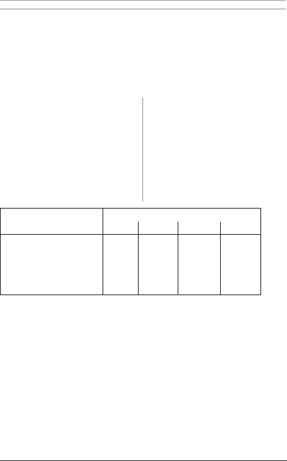
2.1 Communication speed
2.1.1 Data Tag communication
The data transmission speed between
communicator and the Data Tag depends on the
amount of data to read or write.
Table 2.a shows the minimum microwave
communication time needed under ideal
circumstances. If a disturbance would occur, the
communicator will automatically initiate a
retransmission of the data block (16 bytes).
2 System performance
System performance
File size bytes
10 100 1000 4000
Write one file LD
PC 3104/32A, PC3105/00D 0.14 0.16 0.39 1.2
PC 3104/22A 0.06 0.07 0.14 0.37
Read one file RD
PC 3104/32A, PC3105/00D 0.12 0.14 0.32 0.95
PC 3104/22A 0.06 0.06 0.12 0.31
Table 2.a Communication time microwave link

14 Baumer Ident OIS-P, PC3141/03 Manual
System performance
to commands) and reaction time in the host
computer. The host is assumed to react to
command replies in 10 ms. Both this table and the
Data Tag communication time table must be used
to calculate the total time required at a OIS-P
station, when conducting calculations on passage
frequency.
2.1.2 Host communication times
The host communication can be up to 19.200 baud.
The table below displays the time required for
communication between the Host computer and the
Central Unit. The table presents the time required
to transfer file data and commands (or responses
Table 2.b Serial communication times host–central unit (EUROX_4 protocol/8/E/1). Send one
file from the host to the control unit and start the writing into the tag.
Transfer speed File size
bits/sec 10 100 1000 4000
4800 0.16 0.34 2.3 8.5
9600 0.09 0.19 1.13 4.3
19200 0.06 0.11 0.58 2.2
Table 2.c Communication sequence used for calculation of time values in table 2.b.
Host to central unit Central unit to host Time included in table 2.b
PU, 0, <Data> ACK X
LD, 0, 2 ACK X
ST 101 X
ST _ _ _
_ _ _ _ _ _
ST 001
NEXT FILE

OIS-P, PC3141/03 Manual Baumer Ident 15
2.1.3 Total communication time
Point-to-point connection
The total time required for communication between
the host system and the Data Tag is calculated by
adding the Data Tag communication time (Table
2.a) to the host communication time (Table 2.b).
This will result in a total communication time based
on the following conditions:
* The host has a response time of 10 ms.
* The OIS-P system is connected to the host
in point-to-point connection.
If the serial interface response time in the host is
significantly longer than the stipulated 10 ms, the
additional time will have to be added three times.
Multidrop connection
In case OIS-P communicators are connected in a
multidrop configuration, the following guidelines will
apply for determining the total time required for
moving data between Data Tag and host:
a/ If each Communicator’s task is performed
from start to finish, without delay due to host
communication with other units, the total time
required for moving data between Data Tag
and host will be the same as for a point-to-
point connected unit.
b/ However, if the system engineer designs the
application software program in a way, that
the process of moving data between Data
Tag and host may be interrupted by host
communication with other Communicators,
an object must remain in front of an antenna
for a longer time than in a point-to-point
situation.
How much longer this required time will be,
depends on how the system engineer has
designed the application specific software in
the host.
Example
Let’s assume initial production requirements are to
be written to a PC 3105/00D Data Tag at the start
of a production line. The Data Tag is present
(moving or stationary) in the communication zone
for 10 seconds. 30 files with an average size of 100
bytes are to be written. The host communication
baudrate can be chosen to satisfy the time
requirements. The OIS-P is connected to the host
in a point-to-point configuration and the response
time for the host is less than 10 ms.
Time required
at different baud rates
Sequence: 9600: 19200:
Host to central unit time
(30 x 0.19/30 x 0.11) 5.7 3.3
Central unit to escort
memory time
30 x 0.16 4.8 4.8
Total: 10.5 8.1
Table 2.c Example on total communication time.
Result:
The baudrate 19200 should be used for sufficient
margins. A faster solution would be to use the
command buffer. All data can be loaded into one
buffer before the Data Tag arrives to the
communication zone.
With a command buffer containing CO (Copy Buffer
to Buffer) and LD (Load) there is no need for a
communication to the host for every file.
The resulting time in the example above would be
less than 5.0 s., i.e. a recommendable margin of a
factor 2.
System performance
16 Baumer Ident OIS-P, PC3141/03 Manual
System performance
2.2 Communication area
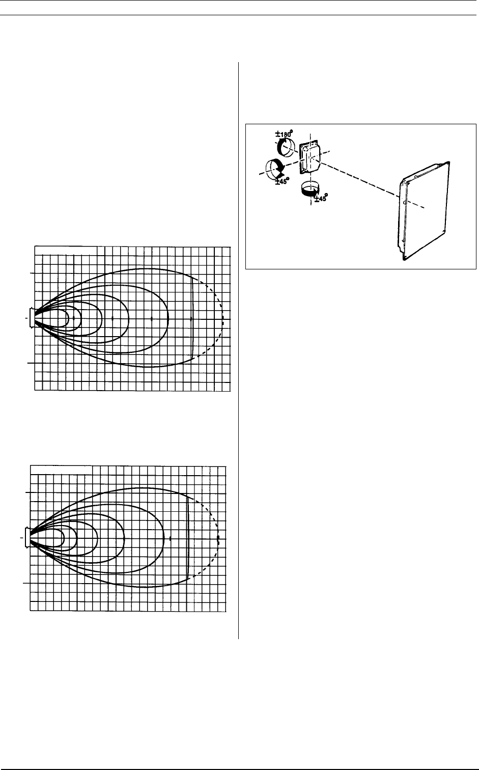
The communication area for the antenna PC3114/
00A (maximum 2 m distance) is shown in Figure
2.1. The diagram assumes a Data Tag temperature
of -40oC - +40oC and a pitch and tilt angle of 0o.
The antenna PC3114/01A has almost twice as
long communication distance (Figure 2.2).
It is always recommended to only utilise 50 to 75%
of the range in free space due to influences in the
actual installation.
Figure 2.1 Communication area, PC3114/00A
Figure 2.2 Communication area, PC3114/01A
Figure 2.3 shows the allowed alignment between
Data Tag and antenna.
Figure 2.3 Freedom of alignment.
0.5
0
0.5
Radium (metres)
0.5 1.0 1.5 2.0
1
0
1
Radium (metres)
1234
OIS-P, PC3141/03 Manual Baumer Ident 17
System performance
2.3 Distance between Data Tags
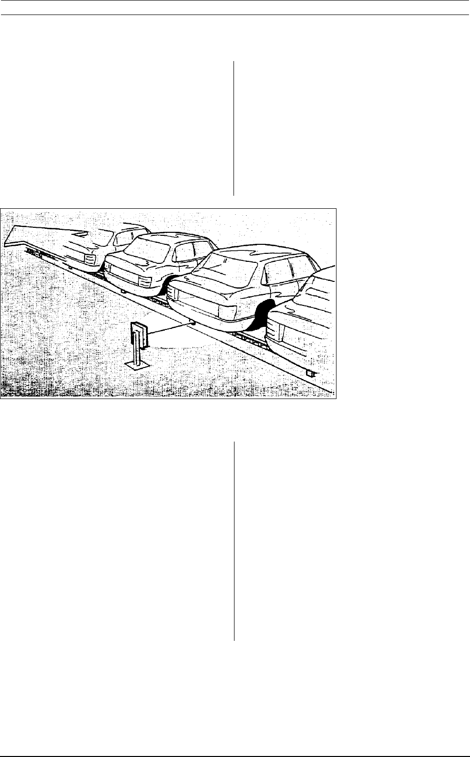
Narrow antenna field
The data transmission frequency of 2,45 GHz
offers many excellent characteristics, of which one
is the ability to “focus” the microwaves on a desired
area, much like a flash light throws out a narrow
beam of light.
Figure 2.4 Focussing on the “right” object thanks to the narrow antenna field.
Data Tag ID-address
To further enhance installation flexibility and ensure
optimum communication reliability, each Data Tag
has a unique identity. The so called ID-address is
factory programmed from a range of more than 16
million (224) ID-addresses. The unique ID-
addresses will ensure that communication initiated
with an Data Tag also can be finalized with the that
particular Data Tag, even if another Data Tag
would come in closer to the antenna. It is thus
important that the ID-addresses remain unique
even if the user reinitialises the tags. The system
is, however, basically designed for one tag in the
lobe and other situations should be avoided.
Distance between Data Tags
It is important that the Data Tag with which
communication is to be established, returns the
strongest signal to the antenna, as the Data Tag
communication is initiated by OD or user
command. To translate that into a minimum
distance between Data Tags, an antenna lobe
diagram must be studied.
The graph lines in figures 2.1 and 2.2 represent
positions of similar signal strength in front of an
antenna. The distance between two graph lines
represent a signal strength difference of 3 dB.

18 Baumer Ident OIS-P, PC3141/03 Manual
The recommendations for how close Data Tags
may be to each other at a communication point are:
1. Ensure at least a 3 dB difference in signal
strength between the intended Data Tag and all
other Data Tags, when communication starts. If
a major difference in Data Tag exposure to
foreign substances like paint etc can be
expected, this difference should be added to the
3 dB mentioned above. Please refer to section
3.3.
2. The closer to each other the Data Tags must
come, the shorter the communication distance
should be. By reducing the communication
distance, it is easier to maintain a significant
difference in signal strength between the
intended Data Tag straight in front of the
antenna and not intended Data Tags.
The closer Data Tags come to each other, the
more important also the timing of object detect
activation becomes. If objects come very close
to each other, OD should be activated as the
correct Data Tag is located straight in front of the
antenna. This however means that part of the
theoretical access range is lost. For
communication with objects at standstill this
means that the object stop position is more
critical. For communica-tion with objects in
motion, it means that the available
communication time is reduced.
3. Recommendation 1 and 2 above prevents that
no communication with other Data Tags will
occur, provided that the intended Data Tag is
present and in operating order. For a better
protection against communication with nearby
Data Tags, these cannot be allowed within an
area, corresponding to 2–5 times the size of the
0 dB graph line in figure 2.1 and 2.2.
Microwaves can, however, be influenced and
reflected by metal and directed into unwanted
areas, which has to be considered in the
installation layout.
Should this description not cover your installation
requirements or should you have any questions,
please consult your OIS-P system specialist for
advice.
2.4 Distance between antennas
To ensure that the antenna only communicates
with the proper Data Tag the recommendations
under section 2.3 must be followed.
To avoid interference between adjacent antennas,
the Interlock function should be used. This means
that two or more antennas avoid to communicate
simultaneously. Since the microwave
communication time is short, this Interlock will
normally not influence the total communication time
notably.
An Interlock function can also be realised by
sequencing the commands in the host (PLC) to the
different control units. Without Interlock the
antennas should be separated 4–10 times the size
of the 0 dB graph line in figure 2.1 and 2.2.
If for some reason the Interlock function can't be
used there is a possibility to use frequency
separated antennas. Please contact your OIS-P
system specialist for advice.
System performance

OIS-P, PC3141/03 Manual Baumer Ident 19
Environmental influence
3.1 General
Since the OIS-P system is a vital part in a usually
complex production process, where products of
high value are manufactured, the highest priority
has been set on maximizing communication
reliability. This means that top performance must
be guaranteed even under severe industrial
environmental conditions.
The OIS-P technology has proven itself capable,
during more than a decade in the automotive
industry, where the environment at times can be
testing; oils, water and other fluids have to be dealt
with, as has electromagnetic fields from welding
robots, paint layers, high temperatures, shock and
vibration and much more.
In the following, the potentially influencing
environmental factors and their consequences for
the installation planning is described.
3 Environmental influence

20 Baumer Ident OIS-P, PC3141/03 Manual
3.2 Metallic objects
Microwaves at 2.45 GHz have an excellent
capability of penetrating through foreign
substances, as described in section 3.3. However,
like all electromagnetic waves, microwaves cannot
penetrate through metallic objects.
Therefore, installations should be planned in such a
way that metallic objects are not present between
antenna and Data Tag when communication with
an Data Tag is to take place. However, small
metallic objects like metal shavings etc will not
influence negatively on the communication.
Further, both Antenna and Data Tags can be
mounted directly onto metal surfaces.
Any system operating in the MHz range or higher,
will have a communication range in which the
signal strength varies, due to wave reflections.
To minimize this phenomenon, the PC3100 system
features circular polarization, which suppresses
microwaves reflected from metal surfaces an odd
number of times. The suppression is equivalent to
6 dB or more.
To avoid the risk of negative interference from
metal surfaces, one of the following situations
should be established.
Environmental influence
A. Communication with the Data Tag is
performed in motion.
Any negative influence of reflections will result in
a slightly longer communication time. This
should be added to the communication time with
a margin dependent on the actual case, normally
a factor 2 (See section 2.1).
B. Communication is performed with the Data
Tag at standstill.
Metal surfaces in positions where they could
reflect microwaves from the antenna towards
the Data Tag should be studied. Generally they
should be at a position equivalent to a 6 dB
lower signal strength than the Data Tag, to
avoid negative influence. This can usually be
achieved by reducing the distance between
antenna and Data Tag.
Depending on reflections there may be points with
stronger or weaker signals and the position of the
antenna and/or the Data Tag should then be
adjusted to achieve a strong signal. The distance
between points with strong signal is normally 12.4
cm.

OIS-P, PC3141/03 Manual Baumer Ident 21
Environmental influence
3.3 Foreign substances between
antenna and Data Tag
Microwaves penetrate through many foreign, non-
metallic substances with no or very little loss of
signal strength. However, if the reduction in signal
strength should be considerable, an appropriate
reduction in communication distance is
recommended as shown in table 3.a.
Substance Rec. signal strength
adjustment (dB/mm)
1st mm Thereafter
Water 7 0.5
Oil 1 0.2
Grease 1 0.1
Regular car paint 1 Note 1
Metallic car paint 3 Note 2
Paper 0.02 0.02
Plastic 0 - 1 0 - 0.05
Snow 0 - 0.5 0 - 0.2
Ice 0.5 0.1
Table 3.a Recommended reduction of
communication distance as a function
of foreign substance layer thickness.
The signal strength adjustment will
vary slightly, depending on the exact
composition of the contamination,
where it is applied etc.
Note 1: Layers beyond 1 mm not
likely. Adjustment for 0.2 mm
amounts to 0.5 dB.
Note 2: Layers beyond 1 mm not
likely. Adjustment for 0.2 mm
amounts to 1.5 dB.
How the recommended signal strength adjustment
relates to the communication distance can be seen
in diagrams in section 2.2.
3.4 Temperature
The antenna lobe diagrams in section 2 are valid
for temperatures up to +40 °C.
If the ambient temperature increases or if the Data
Tags are exposed to higher temperatures than +40
°C, this will result in a reduced signal strength and
a corresponding increase by reduction of the
communication distance should be ensured, as
indicated in table 3.c below.
Product Recommended signal
strength adjustment
+40°°
°°
°C +70°°
°°
°C +110°°
°°
°C
Data Tag
PC3104/32A,/22A 0 dB 2 dB n/a
Data Tag
PC3105/00D 0 dB 2 dB 4 dB
Note 3
Table 3.b Recommended signal strength
adjustment due to ambient temperature.
Note 3: The internal temperature must
be calculated, which will be
done by Baumer Ident on
request.
How the recommended signal strength adjustment
relates to the communication distance can be seen
in diagrams in section 2.2.
Long term exposure of Data Tags to high
temperatures should generally be avoided, as can
be concluded from section 5.2.
3.5 Electromagnetic immunity
The PC3141 system has been EMC-tested
according to the pr ETS 300339 which is required
for the CE-marking. This assures trouble-free
operation in demanding electromagnetical
environments.
Electromagnetic interference in cables
By selecting a suitable communication interface,
using specified cables and proper grounding,
optimum communication reliability is ensured.
Electromagnetic interference on the microwave
link
Industrial noise is typically present in the kHz and
low MHz frequency band. The OIS-P system is
only receptive for frequencies of 2,45 GHz +/- 5%,
so typical industrial noise will not affect the
microwave communication.
Transients from spot-welding equipment or from
switching on other welding equipment, soldering
machines and fluorescent lighting fixtures may
produce short pulses around 2,45 GHz. However,
since the OIS-P system, if interfered, will continue

22 Baumer Ident OIS-P, PC3141/03 Manual
Environmental influence
communication from the point of interference,
rather than having to retransmit an entire message,
such short transients would merely increase the
required communication time by a small fraction.
If strong microwave fields from for instance
industrial microwave dryers can be suspected, an
on-site survey by a OIS-P specialist should be
carried out to determine proper installation
procedures.
3.6. Conclusions on environmental
influence
As shown, the OIS-P PC3141 system is highly
unsensitive to the typical industrial environment.
Still, common sense must be used when planning
an installation and some general rules of thumb
can be established.
1. It is recommended that installation is planned
in such a way, that communication at maxi-
mum specified distance and maximum
specified misalignment is avoided at the same
time. Thereby the access range becomes
longer, thus making object positioning less
critical and the communication capacity higher.
2. To establish if a reduction of the communi-
cation distance should be considered, the
following table will be of help. By adding the
recommended dB signal strength increase for
the factors that apply for your particular instal-
lation and comparing the total with diagrams in
section 2.2, a general understanding of a
suitable decrease in communication distance
is received.
Aspect Rec. signal
strength
adjustment
Metal in/close to the comm. lobe
(section 3.2)
- Communication in motion 0 dB
- Communication at standstill 0 - 6 dB
Foreign substances between
Data Tag and antenna 0 - 3 dB
(section 3.3)
Temperature
(section 3.4)
- Data Tag below +40 °C0 dB
- Data Tag at +70 °C2 dB
- Data Tag at +110 °C4 dB
Electromagnetic interference 0 dB
(section 3.5)
Table 3.c Summary on environmental influence
on communication distance.
Electromagnetic interference and metal in the
communication area when reading in motion, will not
require a reduction of the communication distance.
This will only result in a slightly longer
communication time, which should be added to the
data from the table 2.1.
3. To finally define the optimum communication
distance, on-site testing is recommended. This is
especially important when there is plenty of metal
in the communication area and communicating is
performed at standstill, as table 3.c indicates.
On-site testing is facilitated by the installation
tools available.
OIS-P, PC3141/03 Manual Baumer Ident 23
Health aspects
4 Health aspects
4.1 Emitted power levels
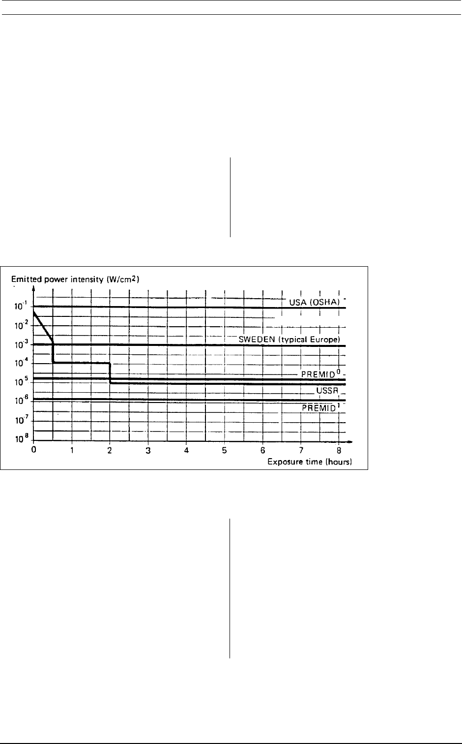
The only emitted power worth mention is the
emission at the data transmission frequency 2,45
GHz. As can be seen from the graph below, the
emitted power is far below all known international
health standards.
Figure 4.1 International health standards for exposure to emitted microwave power.
Radiation density for PC3114/00A at a distance of 0 and 1 meters.
The distance from the antenna in the graph is
defined straight out from the antenna surface, where
the intensity is the highest.
4.2 Health and safety cautions
Normal caution is required when removing the
central unit’s cover. Humans beings have to keep a
safety distance of 20 cm to the antenna.

24 Baumer Ident OIS-P, PC3141/03 Manual
Health aspects
Page intentionally blank.

OIS-P, PC3141/03 Manual Baumer Ident 25
Maintenance aspects
5 Maintenance aspects
5.1 General
The PC3141 OIS-P system is basically a
maintenance-free system. Once correctly installed,
it will deliver many years of trouble-free operation.
In important processes, the user usually collects
and evaluates communication reliability statistics
on a regular basis. These statistics can be
retrieved from the OIS-P communicator as
described in section 7.4 or can be collected at the
user control system level.
5.2 Battery life
General
In order to obtain communication distances in the
meter range, high data speed and still comply to
international telecommunications and health
standards, the Data Tags must be equipped with a
battery.
To get maximum life out of the batteries, the OIS-P
Data Tags are of semi-passive type. The majority
of the time, the Data Tags are passive and only
consuming a few µA. Only during communication,
which typically is ended in a fraction of a second,
will they be active with an increased current
consumption.
The batteries chosen are long-life lithium batteries,
whose life expectancy depend on the amount of
data communication, the data transmission speed
of the Data Tag and the ambient temperature in
which it is used. If the ambient temperature is high,
the battery life will be somewhat reduced. Long
term exposure to high temperatures should
therefore be avoided.
However, for most industrial applications, the
battery life will be longer than 6 to 8 years, as
specified on the Data Tag data sheets.
Battery-low alarm
The remaining battery capacity is automatically
monitored every time communication is established
with an Data Tag. When “battery-low” status is
reported to the user control system, the remaining
battery capacity is 5% and the Data Tag should be
taken out and receive a new battery.
Note: Battery low indication is not reliable
in sub-zero °C temperatures. If
battery-low indication is received in
temperatures below freezing, no
adequate conclusion can be made
from this.

26 Baumer Ident OIS-P, PC3141/03 Manual
Page intentionally blank.
Maintenance aspects
OIS-P, PC3141/03 Manual Baumer Ident 27
Installation
6 Installation
6.1 Mechanical installation
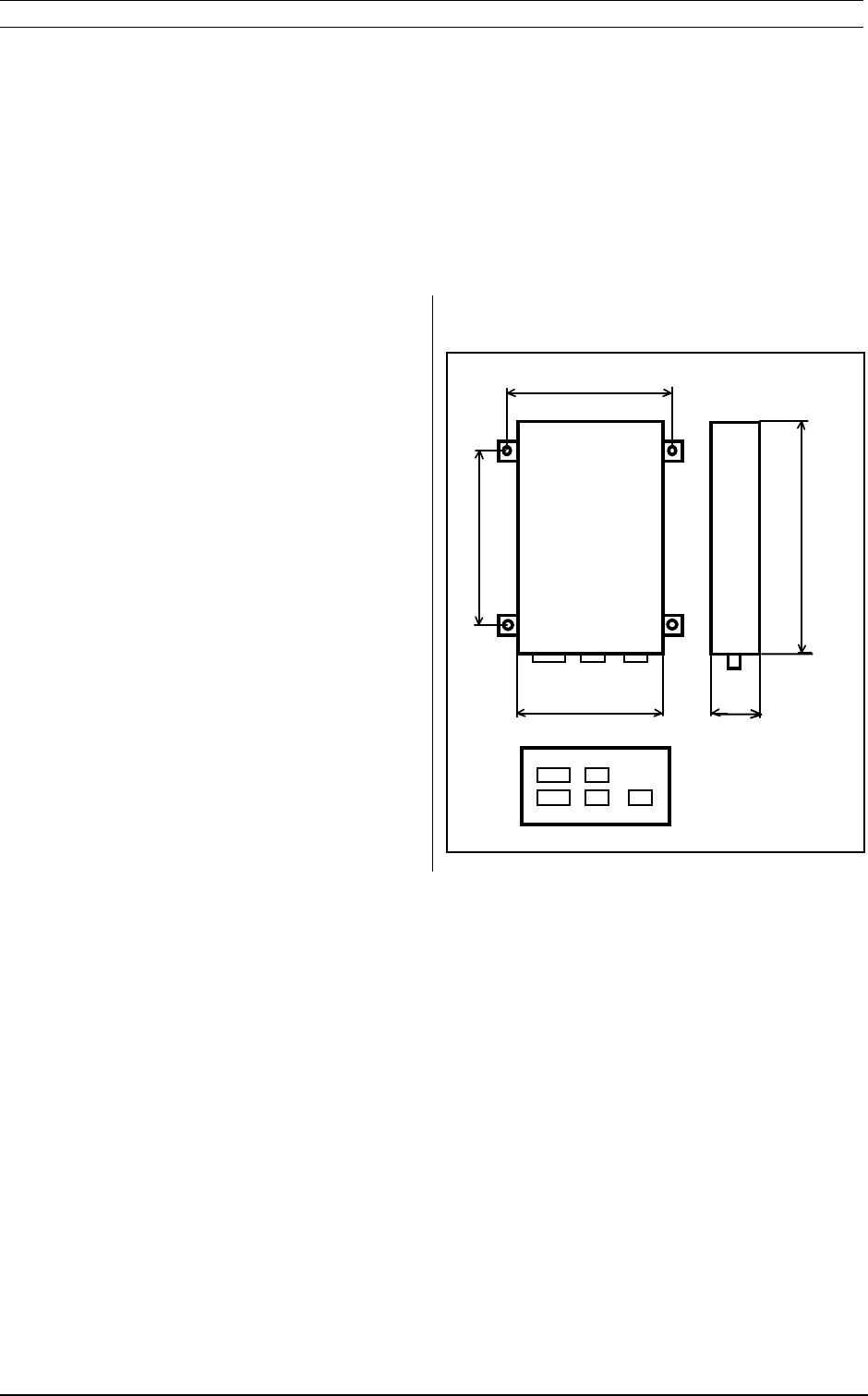
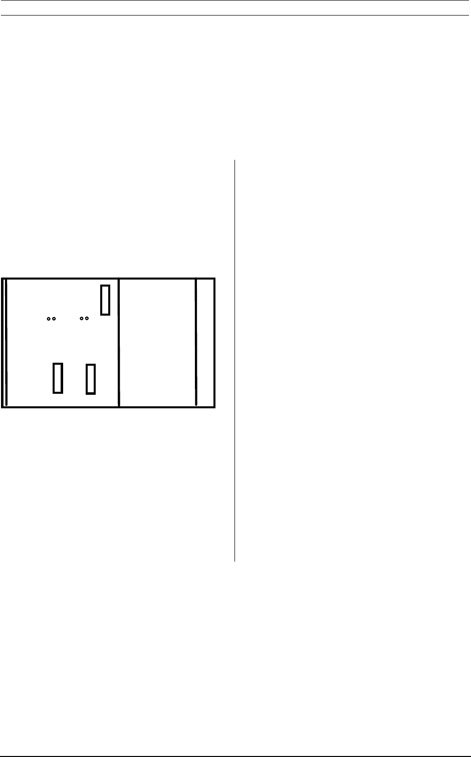
The communicator should be mounted by means of
the four mounting flanges (Diam 8,5 mm) in the
corners of the unit. See Figure 6.1. Use mounting
screws with diam. 8 mm.
Warning
The antenna must be installed at least 20 cm of
persons off.
Figure 6.1 Mechanical dimensions PC 3141/03
I/O TERMINAL
85
HOST ANTENNA POWER
28 Baumer Ident OIS-P, PC3141/03 Manual
6.2 Electrical connection
6.2.1 Power supply and object detect
The unit should be connected to power supply 24
VDC.
An active OD-signal should be represented by a
24VDC voltage on the OD input. There are totally 6
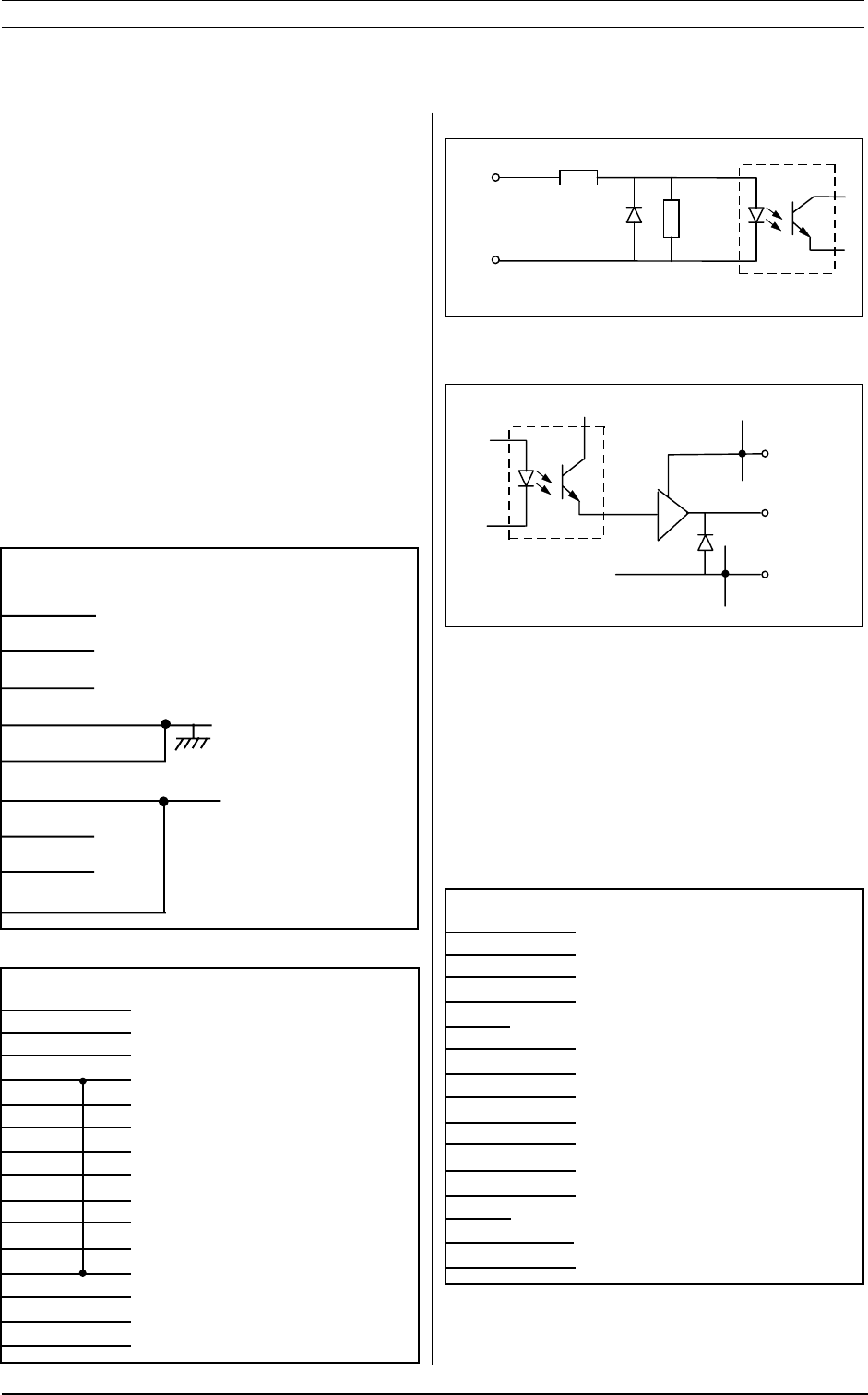
digital inputs and 6 digital outputs available.
The connection is done to POWER and I/O, see
Figure 6.2, 6.3 and 6.4. POWER is a male 9 pin D-
Sub 9 connector. Use cable connector D-Sub 9
female.
Figure 6.2 Power and I/O connection
Installation
POWER
PC3141/03
1
2
3
4
OV
5
6
+24VDC
7
8
9
}
I/O
PC3141/03
OUT5
OUT3
OUT1 (BSY)
+24VDC
IN5
IN3
IN1 (RALA)
OV
OUT4
OUT2 (LOCK)
OUT0 (ALA)
+24VDC
IN4
IN2 (LOCK)
IN0 (OD)
1
2
3
4
5
6
7
8
9
10
11
12
13
14
15
For RS485 and current loop connection also see
figure 6.6, 6.7, 6.8.
HOST
PC3141/03
CLI-
RxD RS232
TxD RS232
CLO-B
RxD –RS485
GND
TxD +RS485
CLI+
RTS
CTS
CLO-A
RxD +RS485
TxD –RS485
1
2
3
4
5
6
7
8
9
10
11
12
13
14
15
Figure 6.3 Interface circuit, input
,1
N
Figure 6.4 Interface circuit, output
'
&%
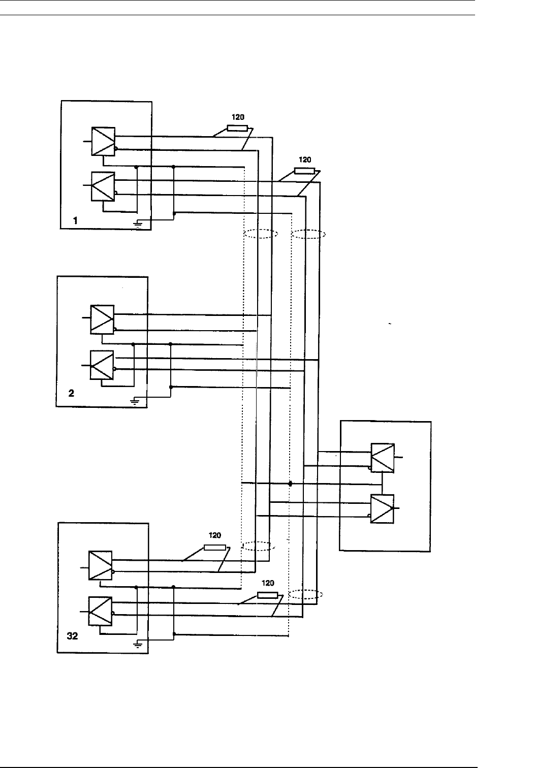
6.2.2 Serial communication (HOST)
The serial interface is RS232, RS485 or passive
current loop. The connection is done to HOST, see
Figure 6.5. HOST is male 15 pin D-Sub connector.
Use cable connector D-Sub 15 female.
Figure 6.5 Serial connection
OIS-P, PC3141/03 Manual Baumer Ident 29
PC 3141/03
8
15
7
14
6
SHIELD
HOST
HOST
8
15
7
14
6
SHIELD
SHIELD
HOST
8
15
7
14
6
Installation
Figure 6.6 RS485 multidrop configuration
HOST
PC3141/03
PC3141/03
30 Baumer Ident OIS-P, PC3141/03 Manual
,1
N
Installation
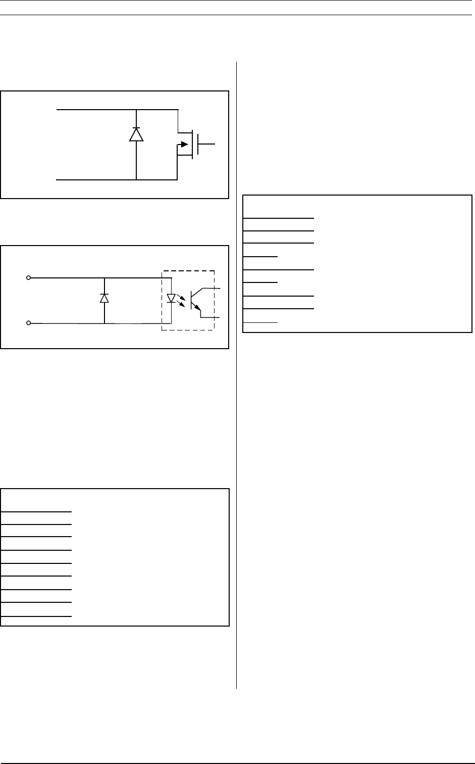
6.2.4 Test terminal
The test terminal is connected to TERMINAL, see
Figure 6.10. TERMINAL is a male 9 pin D-Sub
connector.1500AO. Use cable connector D-Sub 9
female.
Figure 6.10 Test terminal connection
6.2.3 Antenna connection
The central unit PC3141/03A uses a separate
antenna conntected to ANTENNA according to
figure 6.9. ANTENNA is a D-Sub 9 female connector.
Figure 6.9 Antenna connection
For order codes of antenna connection cables, see
section 1.2.
The connection to the antenna must be done with a
shielded cable.
Figure 6.7 Current loop passive transmitter
Figure 6.8 Current loop passive receiver
HOST
CLI+
CLI-
CLO B
CLO A
ANTENNA
PC3141/03
GND
RESERVED IN
RESERVED IN
PF–
EN+
+18V
RESERVED OUT
PF+
EN–
1
2
3
4
5
6
7
8
9
RESERVED
RxD
TxD
GND
RTS (NOT USED)
CTS (NOT USED)
1
2
3
4
5
6
7
8
9
TERMINAL
PC3141/03
When the test terminal is not connected, the
contact must be protected with the cover.
This connection is only intended for test purpose
and is not optoisolated. This means that it should
be used with care, e.g. with a short, shielded cable
and should not be permanently connected.
The terminal can also be used to examine the list of
the most recent error codes, host communication
messages and to test the communicator to a Data
Tag.
HOST
4
12
9
1
{{
{{
{
{{
{{
{
OIS-P, PC3141/03 Manual Baumer Ident 31
Installation and trouble-shooting tools
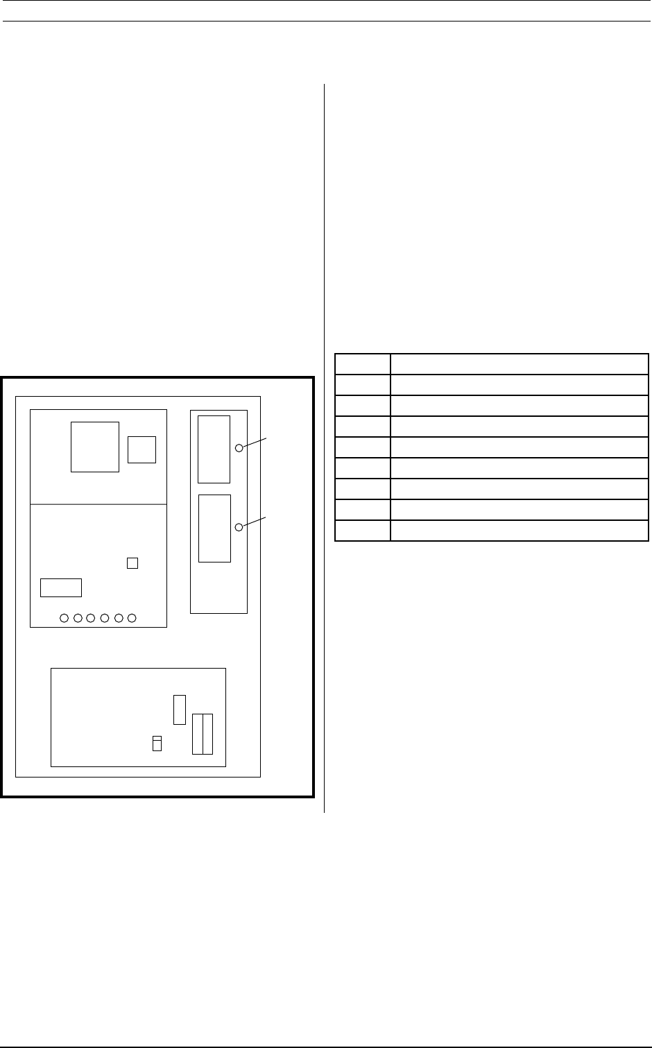
7.1 Communicator Set-Up
The Set-Up of selectable communicator functions is
done by opening the cover of the unit. This will
reveal the CPU4-board that contains DIL-switches
as in Figure 7.1 below.
Figure 7.1 CPU4 board lay-out
boar
The CPU-4 board has 3 sets of DIL switches which
are used to set functional options.
SW1:1
On: Object detect to be used (default)
SW1:2
On: Status to be sent automatically
Off: (default)
SW1:3
On: Extended I/O ( 5 inputs and
6 outputs available)
Off: (default)
SW1:4
On: Timeout option used (4 s) (default)
SW1:5
On: Delayed response (50 ms)
Off: (default)
SW1:6
On: High priority commands
allowed (AP)
Off (default)
SW1:7
Off
SW1:8
Off
The use of SW2 is depending on the used
communication protocol.
7 Installation and trouble-shooting

32 Baumer Ident OIS-P, PC3141/03 Manual
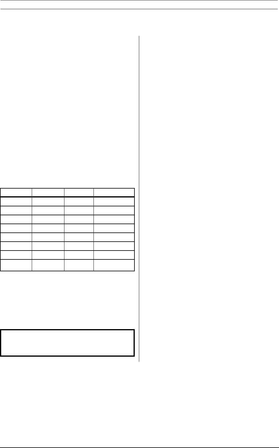
If 3964R protocol is used:
SW2:1-3:
Block length:
Block length 2:3 2:2 2:1
16* Off Off Off
32 Off Off On
64 Off On Off
128 Off On On
256 On Off Off
512 On Off On
1024 On On Off
252 On On On
SW2:4,5:
Character timeout:
Character
timeout ms 2:5 2:4
220* Off Off
330 Off On
440 On Off
550 On On
SW2:6,7:
Acknowledge timeout:
Acknowledge
timeout s 2:7 2:6
2* Off Off
3OffOn
4OnOff
5OnOn
*Default
Installation and trouble-shooting tools
SW 2:8
Off: Eurox protocol used
On: 3964 R protocol used
If EUROX protocol is used:
SW2:1-5:
Communicator address
Addr 2:5 2:4 2:3 2:2 2:1
0* Off Off Off Off Off
1 Off Off Off Off On
2 Off Off Off On Off
3 Off Off Off On On
4 Off Off On Off Off
5 Off Off On Off On
6 Off Off On On Off
7 Off Off On On On
8 Off On Off Off Off
9 Off On Off Off On
: Off On Off On Off
; Off On Off On On
< Off On On Off Off
= Off On On Off On
> Off On On On Off
?OffOnOnOnOn
@ On Off Off Off Off
A On Off Off Off On
B On Off Off On Off
C On Off Off On On
D On Off On Off Off
E On Off On Off On
F On Off On On Off
GOnOffOnOnOn
H On On Off Off Off
I On On Off Off On
J On On Off On Off
KOnOnOffOnOn
L On On On Off Off
MOnOnOnOffOn
NOnOnOnOnOff
OOnOnOnOnOn
OIS-P, PC3141/03 Manual Baumer Ident 33
Installation and trouble-shooting tools
SW3:1
On Host 8 bits data (default)
Off 7 bits data
SW3:2
On Host Even parity (default)
Off Odd parity
SW3:3
On Parity bit used (default)
SW3:4
On Host 2 stop bits.
Off 1 stop bit (default)
SW3:5
On Host CTS signal is used.
Off: (default)
SW3:6-8:
Host baudrate:
Baud SW3:8 SW3:7 SW3:6
150 Off Off Off
300 Off Off On
600 Off On Off
1200 Off On On
2400 On Off Off
4800 On Off On
9600* On On Off
19200** On On On
* Default
** Not for current loop
WT3, WT4 jumpers
WT3 present = long INTERLOCK
WT4 present = short INTERLOCK
Default is no jumper.
After any change of DIL switch or jumper
settings, the communicator must be reset
(power on).
7.2 Test methods and error codes
The status of the Central Unit can be observed by:
– Test terminal. A PC with a terminal emulating
software can be connected to the connector
TERMINAL of the PC3141/03. Here the list of
the most recent error codes as well as the host
communication can be observed. See below.
– LEDs on the CPU and power board show the
present status on data communication and
power supply.
The error code on the TERMINAL consists of 2
characters CH0 and CH1. The meaning of this
code is more described in the Programmers'
Manual.
CH0 Central Unit Operation status
The value 3 means that an error has been
detected.
CH1 Error codes
0 Illegal file number
1 File overflow
2 Data buffer overflow
3 File protection alarm
4 High priority alarm
5 Not used, reserved for future use
6 Invalid data
7 Data Tag test failed
8 Data Tag unreadable
9 File unreadable
A Object detect alarm
B Object detect alarm, no command
C Not used
D Data Tag communication timeout
E Not used
F Initialized (“power on”)

34 Baumer Ident OIS-P, PC3141/03 Manual
Installation and trouble-shooting tools
7.3 PC program for
communication test
The PC3100 product range includes a menu driven
PC program for the EUROX_4 protocol PC 3100/
90A, (CMD3120) which allows communication with
the OIS-P system from an IBM compatible PC/XT/
AT personal computer, operating on DOS and having
at least one serial port, configurable as “COM1” or
“COM2”.
The program features three modes:
High level: Commands can be issued in a very
simple way, such as “read file”, “write to file” etc.
Basic system functionality is easily executed, to
get acquainted with the system or for basic
installation testing.
Low level: Commands are entered in low-level
language, exactly as they are described in the
Programmer’s Manual. The entire command list
can be executed, offering, for instance the
programmer, a hands-on possibility to get
acquanted with the full range of user commands
and command parameters.
Verifier level: Allows verification of execution
reliability for user-definable communication tasks.
The user can enter a sequence of low-level
commands including possible time-delays, to
resemble a typical communication task and
situation. The entered sequence is executed
repeatedly, when Object detect is indicated “active”
to the central unit. Communication reliability
statistics and measured execution
time (maximum, average and minimum) is
continously stored and displayed.
7.4 Built-in communication
reliability statistics
The PC3141/03 central units have a built-in
statistics function, which keeps a count on the
system’s communication reliability. The statistics
count is initiated as soon as power is connected to
the system and a command is received.
These communication statistics are available by
connecting a VT100 (19200 baud, 7 bits, even
parity, one stopbit) compatible terminal to the
Terminal ports RS232 interface. The accumulated
status of four different communication parameters
is displayed simultaneously:
ESuccessful microwave commands
EUnsuccessful microwave commands
ESuccessful microwave operations
EE
EE
EUnsuccessful microwave operations
Definitions: Microwave commands are user
commands that request communication with an
Data Tag.
The execution of every microwave command
requires a number of microwave operations.
EE
EE
EEvery unsuccessful microwave command
verifies that a user request for any reason was
not executed, i.e. a reading or a writing task was
not performed. An investigation of the Data Tag
and/or Communicator in question should be
undertaken.
EE
EE
EAn unsuccessful microwave operation does
not verify that any communication between user
system and Data Tag has failed. It only states
that a greater number of microwave operations
that the theoretical minimum was needed to
execute the requested communication task. The
installation should however be made and
verified in such a way that the number of
unsuccessful microwave operations are as
insignificant as possible compared to the
successful ones. This way, a highly reliable
communication point is ensured.
The stored statistics will be erased as power to
the central unit is shut off. A new statistics count
will automatically start when the power is switched
on again.
All counters are limited to 65 535 (then restart from
0).
OIS-P, PC3141/03 Manual Baumer Ident 35
7.5 Internal inspections and tests
7.5.1 General
If the investigations in the previous sections is not
sufficient to find the cause of a problem or if the
communicator does not operate at all an internal
inspection is required to find out if there is a
connection error or if any main part of the
communicator fails.
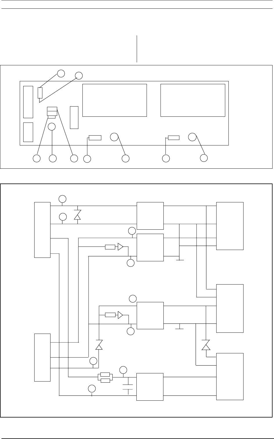
The Figure 7.3 shows an internal view of the
communicator. The main parts are the Connector
Board (down), the CPU Board (left) and the Power
Board (right).
Figure 7.3
Installation and trouble-shooting tools
7.5.2 Connector Board and fuse
The power to the unit is supplied via the connector
(down right), the protection diode CR1 and the fuse
F1.
The type of fuse is: Fast 1 A, 5 mm * 20 mm.
7.5.3 LED indications
The positions of the internal LED’s are shown in
Figure 7.3.
CR2 and CR3 show the power status and CR9 to
CR14 show the status of the host and antenna
communication.
LED Description
CR2 Electronics supply voltage OK
CR3 Antenna voltage OK
CR9 CPU is running
CR10 Object detect is active
CR11 Host receive signal
CR12 Host transmit signal
CR13 Antenna transmit signal
CR14 Antenna receive signal
Table 7.a
PLD
–
C50
+
C9 10 11 12 13 14
PROM
CR2
CR3
IA–F
F1
CR1
24V + 0
10
9
IC40
36 Baumer Ident OIS-P, PC3141/03 Manual
Installation and trouble-shooting tools
7.5.4 Power Board
The power board contains power supplies for the
internal electronics, the antenna and the host
communication current loop transmitter.
Figure 7.4 and 7.5 show the recommended
measuring points and table 7.b the specified
voltage values.
Figure 7.4
Figure 7.5
G
AB
C D E FHI
JP2 JP1
R2 CR3 R1 CR2
JP3
C14
CR4
CR6
A
B
H
I
F
G
C
E
D
24 V 1,2
0V 3,4
CL 5
CL 6
+5V 2
04
+18V 1
CR6
R1 CR2
FILTER
FILTER
FILTER
FILTER
24V/
5V
24V/
±15V
24V/
±12V
R2 CR3
CR4
R5
C14 +
R5
NOT
USED
OIS-P, PC3141/03 Manual Baumer Ident 37
Installation and trouble-shooting tools
Points Description Voltage value
A - B External supply +24 V
C - G Antenna voltage +18V +/- 0,5 V (with
antenna connected)
E - D Not used +24V +5/-2V
F -G Antenna supply + 30V +/- 0,5V
H - I Electronics supply +5V +/- 0,1 V
Table 7.b
Figure 7.6 shows the power supply connection
circuit with the protection diode CR1 and the fuse
F1.
7.5.5 CPU Board
The Figure 7.3 shows the CPU Board in the upper
left corner.
The upper part of the figure shows the position of
the PROM and PLD which may have to be
replaced in the case of a system upgrade.
The Figure 7.3 also shows two voltage measuring
points:
EInsulated external I/O supply: measure 24V
between IC40:9 and IC40:10
(if this voltage is connected).
ECPU supply voltage: measure 5 V between
C50 + and C50 -
+24V
CR1 F1
4
5
06
90
+
Fig 7.6
POWER

38 Baumer Ident OIS-P, PC3141/03 Manual
Installation and trouble-shooting tools
Page intentionally blank.

OIS-P, PC3141/03 Manual Baumer Ident 39
Technical Data
8.1 Communication parameters
Compatibility
Compatible with 8 kbyte Data Tags
PC3104/32A,/22A and PC3105/00D.
Data Tag format not compatible with
earlier PC3100/00.
Communication range
Depending on antenna type used, 0 to 2
meter for PC3114/00A and 0 to 4 m for
PC3114/01A in free space, see figure 2.1.
It is always recommended to only utilise
50 to 75% of the range in free space due
to influences in the actual installation.
Communication speed
(Antenna to tag)
See table in chapter 2.
Communication protocol
EUROX_4
3964R
8.2 Mechanical specification
Weight
3,8 kg
Size
300 x 200 x 85 mm
Casing material
Steel
Casing integrity
IP41
IP65 with extra protection for connectors
ref. IEC 529
Colour
Grey
Mounting
by means of 4 mounting flanges for M8 bolts.
8.3 Electrical specification
Power supply
18 to 36 VDC
Power consumption
10 W maximum (operation)
Startup current 6 times higher
6 W maximum (idle mode)
Digital inputs
24 V AC or DC, 15 mA, optoisolated.
Digital outputs
24 V DC, 60mA, optoisolated.
Interfaces
Host (optoisolated)
RS 232 (150-19200 baud)
RS 485 (150-19200 baud)
Current loop (20 mA) passive
(4800,9600 baud)
Terminal (not optoisolated)
RS232 19200 baud 7 bit, Even parity,
1 stopbit
Connectors
One connector for power (D Sub 9 male)
One connector for serial communication
(D Sub 15 male)
One connector for test terminal
(D Sub 9 male)
One connector for antenna
(D Sub 9 female)
One connector for digital I/O
(D Sub 15 female)
Frequency
2,45 GHz
Emitted power intensity
Max 25 µW/cm2 at 0 cm distance from the
unit.
Max 1,5 µW/cm2 at 100 cm distance from
the unit, for PC3114/00A.
Max 4 µW/cm2 at 100 cm distance from
the unit, for PC3114/01A.
8 Technical Data

40 Baumer Ident OIS-P, PC3141/03 Manual
Technical Data
8.4 Cable specifications
Host connection cable
Depending of the interface chosen the cable with the
following specification must be used :
Common data :
Max AWG 24 AWG
Min copper area 0.22 mm2
Design Twisted pairs, Note 1
Shielding Per pair
Nominal impedance 100 Ohm
Maximum diameter12 mm
Minimum diameter 8 mm
Number of wires 2 x 2 (twisted pairs)
Note 1
Voltage rating 150 V
Cable for current loop interface
Maximum length 1000 m
Nominal capacitance
between conductors 28.5 pF/m
Recommended cable type Belden 9184
Cable for RS-485 interface
Maximum length 1200 m
Nominal capacitance
between conductors 50 pF/m
Recommended cable type Belden 9729
Cable for RS-232-C interface
Maximum length 15 m
Note 1. For RS232: 5 separate wires.
Antenna cable
The connection to the antenna must be done with a
shielded cable. Available Premid Antenna cables
and connectors are listed under “accessories” in
section 1.2 Cable specification is as follows:
Common data :
Max AWG 24 AWG
Min copper area 0.22 mm2
Maximum diameter 8,5 mm
Minimum diameter 7,8 mm
Design Twisted pairs
Impedance +/- 20% 120 Ohm
Shielding Common
Temperature rating 70oC
Voltage rating 30 V
Nominal capacitance
between conductors 50 nF/1000m
DCR of conductors 80 Ohm/1000 m
Number of wires 4 twisted pairs. Note
Maximum cable length100 m
Cable type Belden 9831, DUE
4404 (DUE 7065),
Pirelli, Dataflex 55
Recommended cable PC 3017/02A
Note: Two pairs for power supply must be
connected in parallel to achieve the following
specification:
Total DC resistance max 8 ohm (loop)
DC resistance max 40 ohm/Km
Copper area min 0,44mm2

OIS-P, PC3141/03 Manual Baumer Ident 41
Technical Data
Terminal cable
For connection of the terminal a cable with the
following specification must be used :
Max AWG 24 AWG
Min copper area 0.22 mm2
Shielding Common
Maximum diameter12.0 mm
Minimum diameter 8 mm
Maximum length 3 m
Number of wires 3
Digital inputs/outputs cable
Max AWG 24 AWG
Min copper area 0.22 mm2
Maximum diameter12.0 mm
Minimum diameter 8 mm
Maximum length 100 m
Shielding Common
Other parameters as the cable length, number of
pairs, DC resistance etc. must be chosen
according to the application requirements.
All cables.
Metal housing connected to shield and ferrite close
to Central Unit is required.
8.5 Environmental specification
Temperature range
-40 to +70 °C (storage)
+5 to +40 °C (operating)
Vibration
Sine: ±0.35 mm 10-60 Hz,
1g 60-150 Hz
in ± 3 axis.
Ref.: IEC 68-2-6 Test Fc
EMC
According to pr ETS 300339 including:
Emission EN550022, class B
Immunity ENV 50141 80-1000 MHz
3V, AM 80% at 400 Hz
EFT/burst IEC 801-4 2 kV
ESD test IEC 801-2 4/8 kV

42 Baumer Ident OIS-P, PC3141/03 Manual
Page intentionally blank.

OIS-P, PC3141/03 Manual Baumer Ident 43
Notes
Notes
_____________________________________________________________________________________
_____________________________________________________________________________________
_____________________________________________________________________________________
_____________________________________________________________________________________
_____________________________________________________________________________________
_____________________________________________________________________________________
_____________________________________________________________________________________
_____________________________________________________________________________________
_____________________________________________________________________________________
_____________________________________________________________________________________
_____________________________________________________________________________________
_____________________________________________________________________________________
_____________________________________________________________________________________
_____________________________________________________________________________________
_____________________________________________________________________________________
_____________________________________________________________________________________
_____________________________________________________________________________________
_____________________________________________________________________________________
_____________________________________________________________________________________
_____________________________________________________________________________________
_____________________________________________________________________________________
_____________________________________________________________________________________
_____________________________________________________________________________________
_____________________________________________________________________________________
_____________________________________________________________________________________

44 Baumer Ident OIS-P, PC3141/03 Manual
_____________________________________________________________________________________
_____________________________________________________________________________________
_____________________________________________________________________________________
_____________________________________________________________________________________
_____________________________________________________________________________________
_______________________________________________________________________________________
_______________________________________________________________________________________
_______________________________________________________________________________________
_______________________________________________________________________________________
_______________________________________________________________________________________
_______________________________________________________________________________________
_______________________________________________________________________________________
_______________________________________________________________________________________
_______________________________________________________________________________________
_______________________________________________________________________________________
_______________________________________________________________________________________
_______________________________________________________________________________________
_______________________________________________________________________________________
_______________________________________________________________________________________
_______________________________________________________________________________________
_______________________________________________________________________________________
_______________________________________________________________________________________
_______________________________________________________________________________________
_______________________________________________________________________________________
_______________________________________________________________________________________
_______________________________________________________________________________________
_______________________________________________________________________________________
_______________________________________________________________________________________
Notes

OIS-P, PC3141/03 Manual Baumer Ident 45
Documentation feedback
Documentation feedback
Your opinions are important to us because we want our Manuals to best meet your needs. By completing
and returning this form you will help us make the next issue of this Manual even better.
Usefulness Yes No
Manual: OIS-P PC 3100/01 series, 8kbyte Communicators PC3141/03
System Description and Installation Manual
Order No: B 1030 200
1. Does the information in the Manual cover your needs? VV
VV
VVV
VV
V
Clarity
2. Are the instructions easy to understand? VV
VV
VVV
VV
V
3. Are the examples clear? VV
VV
VVV
VV
V
4. Are there sufficient examples? VV
VV
VVV
VV
V
5. Is the technical language clearly explained? VV
VV
VVV
VV
V
6. Are the abbreviations easy to understand? VV
VV
VVV
VV
V
7. Are the pictures/drawings clear and easy to understand? VV
VV
VVV
VV
V
8. Are the references clarifying? VV
VV
VVV
VV
V
Disposition
9. Does the table of contents make it easy to find information
in the Manual? VV
VV
VVV
VV
V
10. Are chapter headings self-explanatory and informative? VV
VV
VVV
VV
V
11. Is the information in the appropriate order? VV
VV
VVV
VV
V
Comments: Please make any additional comments, preferably with reference to the above questions,
below.
Name: ...........................................................................................................................
Company: ...........................................................................................................................
Department: ...........................................................................................................................
Address: ...........................................................................................................................
Telephone No: .................................................. Fax No: ...........................................................
e-mail:
........................................................................................................................
Thank you for your help!

46 Baumer Ident OIS-P, PC3141/03 Manual
Postage
Baumer Ident AB
Product Documentation
Box 134
S-561 22 Huskvarna
Sweden
___ Fold in middle and seal with tape. ___
OIS-P Documentation