Baxi Solarflo In Roof Tile Quick Start Guide 5121651
2014-11-12
: Baxi Baxi-Solarflo-In-Roof-Tile-Quick-Start-Guide-106955 baxi-solarflo-in-roof-tile-quick-start-guide-106955 baxi pdf
Open the PDF directly: View PDF ![]() .
.
Page Count: 24
© Baxi Heating UK Ltd 2011
GUIDANCE NOTES
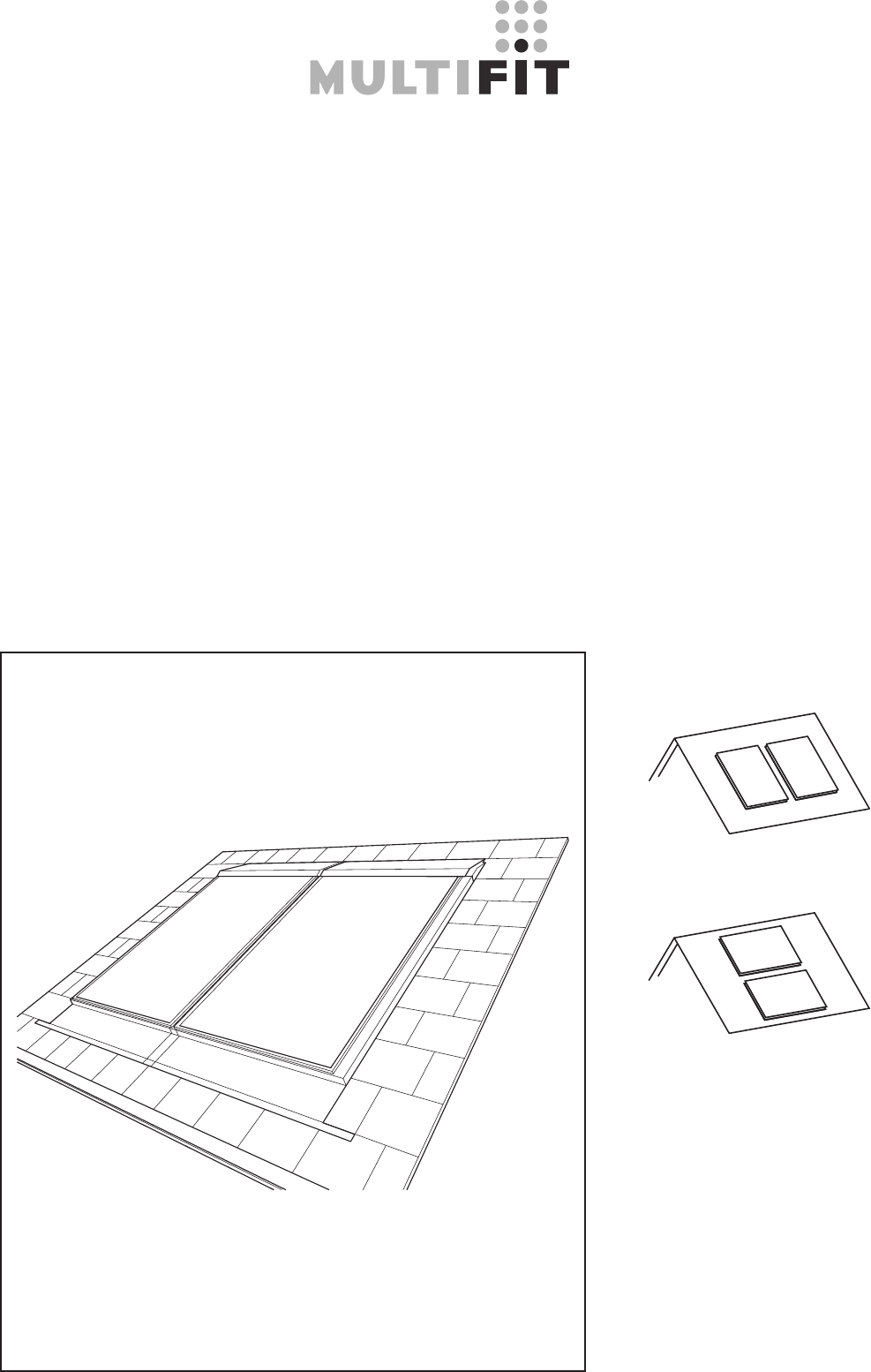
Solar Collectors
In-Roof Tile Installation (First Fix)
Please leave these instructions
with the User

2
Contents
© Baxi Heating UK Ltd 2011
3
4
5
6
8
11
12
13
16
20
24
1.0 Legislation
2.0 General Layout
3.0 Icon Quick Reference Guide
4.0 Dimensions
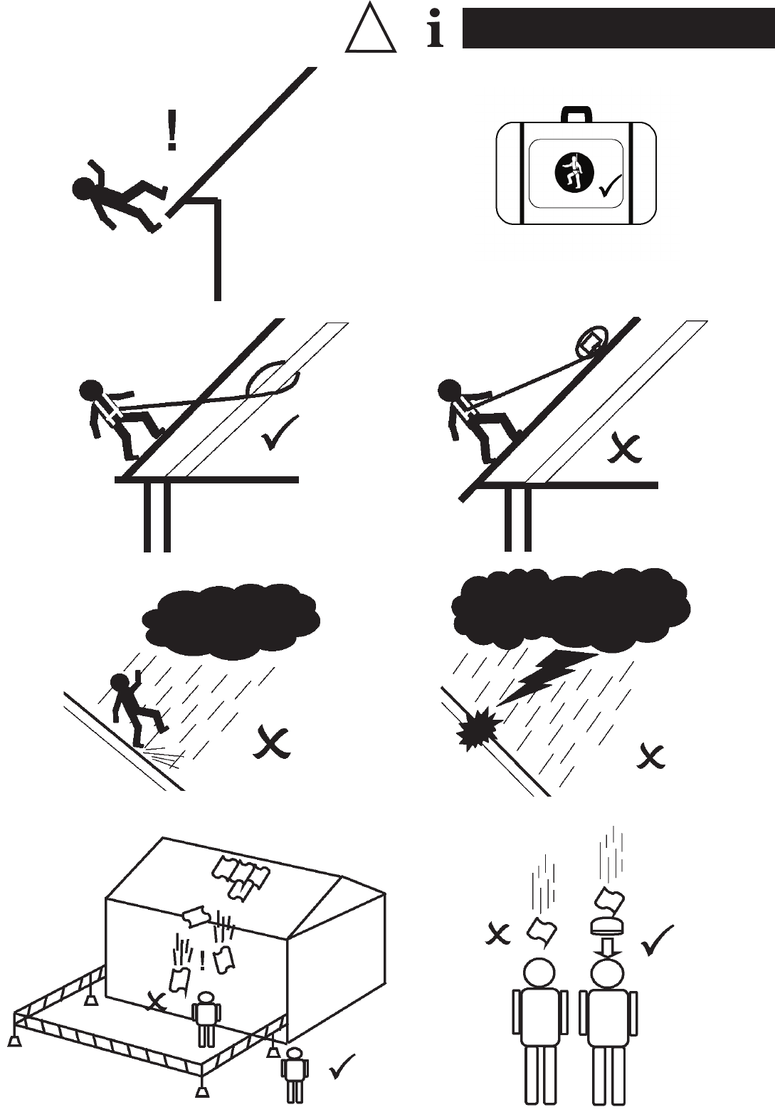
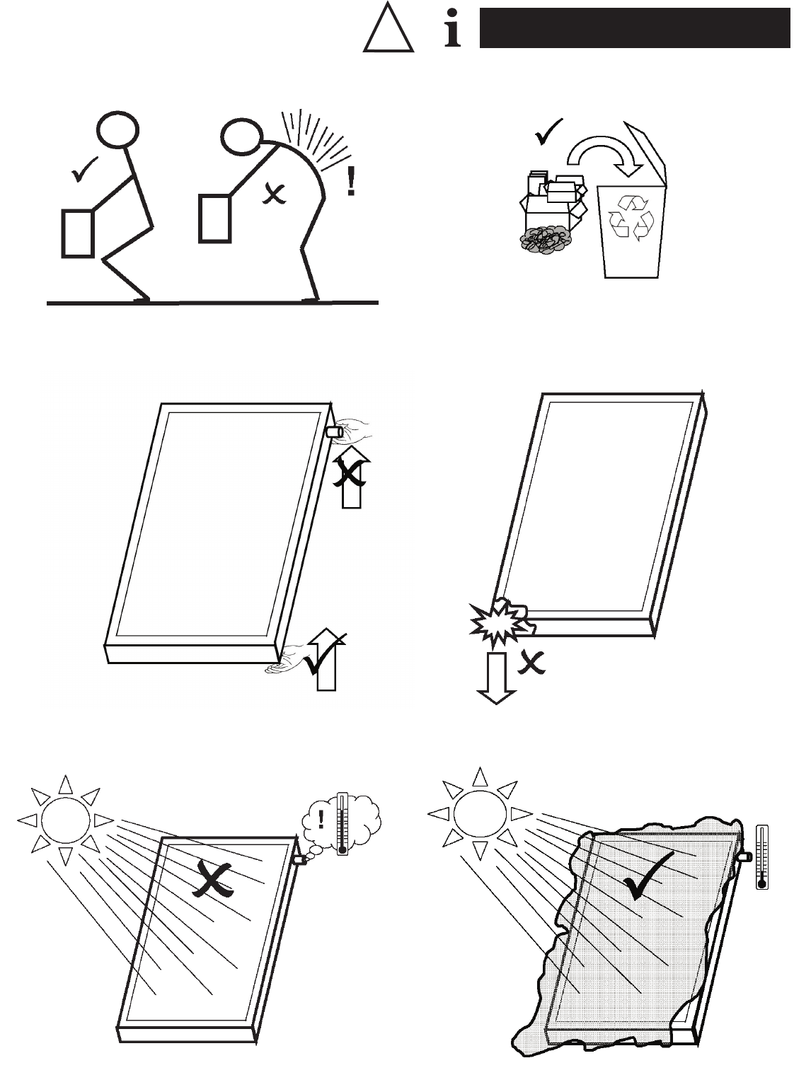
5.0 Health & Safety
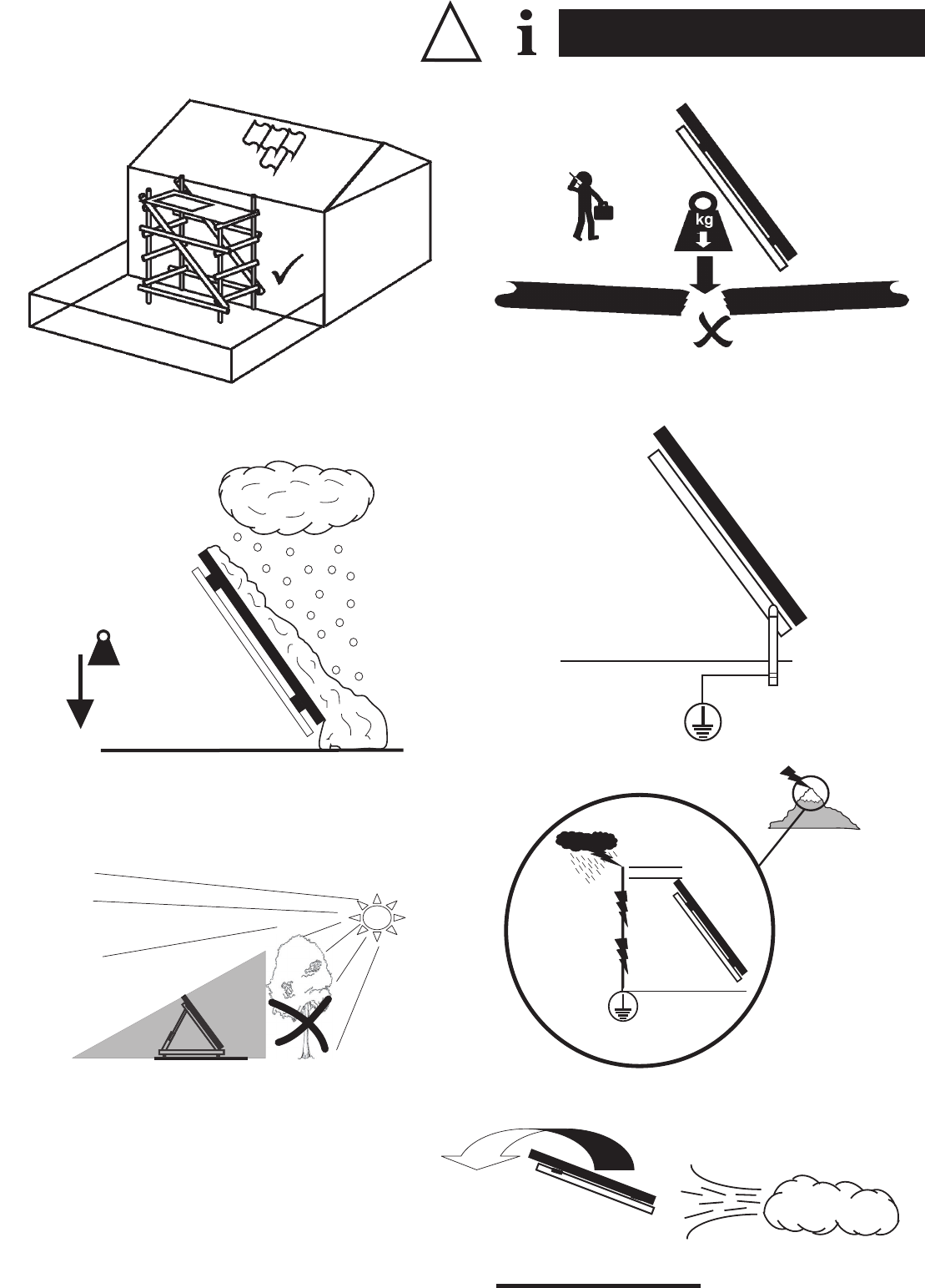
6.0 Snow & Wind Load
7.0 Optimum Pipework Assembly
8.0 Kit Contents and Components
9.0 Installation of the Collector
10.0 Fixing the Flashing
11.0 Maintenance

3
1.0 Legislation
© Baxi Heating UK Ltd 2011
Please note the following instructions regarding laws,
regulations and technical rules.
When setting up solar energy installations, the laws and
regulations at local, state, European and international level that
apply to the country in question must be observed. Generally
acknowledged technical regulations apply; these are usually
formulated in the form of standards, guidelines, provisions,
regulations and technical rules laid down by local and national
bodies, energy supply companies, trade organisations and
technical committees in the relevant fields. The installation of
solar units may require improved rain resistance with regard to
roof, wall and sealing technology and this must be taken into
account accordingly. To meet regulations for the prevention of
accidents, it may be necessary to use safety equipment (straps,
scaffolding, supports, etc.). Such safety equipment is not
supplied and must be ordered separately. Installation must only
be carried out by technically qualified and authorised personnel
with a recognised qualification (verified by a state or national
body) in the relevant technical area.
Use a safety harness when working at height.
The structure of the roof must be assessed for its suitability
prior to commencing work.
This product is unclassified against BS 476-3.
Consult a Structural Engineer if you are unsure of the
collector’s siting.
Loading due to snow may exceed the capability of the
property’s structure.
Wind loads may cause excess forces on the structure and
cause damage.
The Installer is responsible for the suitability of the site and its
sub-structure.
The collector should be sited to avoid damage from falling
debris and vandalism.
All pipe work within this installation must be Earth bonded.
In exposed areas, the collector must be protected against the
risk of lightning.
It is recommended that a minimum of 2 people are used to lift
this product.
The collector must not be lifted by its pipe connections.
Ensure all hydraulic connections are securely fixed and are free
of leaks.
The system must be inspected on completion of the work.
A further inspection is recommended annually.
Avoid installing the collector in shaded areas.
The general recommended torque setting for nuts and bolts is
10Nm.
A separate second array can be installed behind the first if
necessary.
Large arrays will require specialist piping, pump groups and
design.
The collector must not be installed on an uneven roof surface.
Do not apply excessive force when installing the collector.
Hot, exposed surfaces that can be touched must be insulated
to protect against injury.
Lubrication is not required for the ‘O’ ring connections.
4
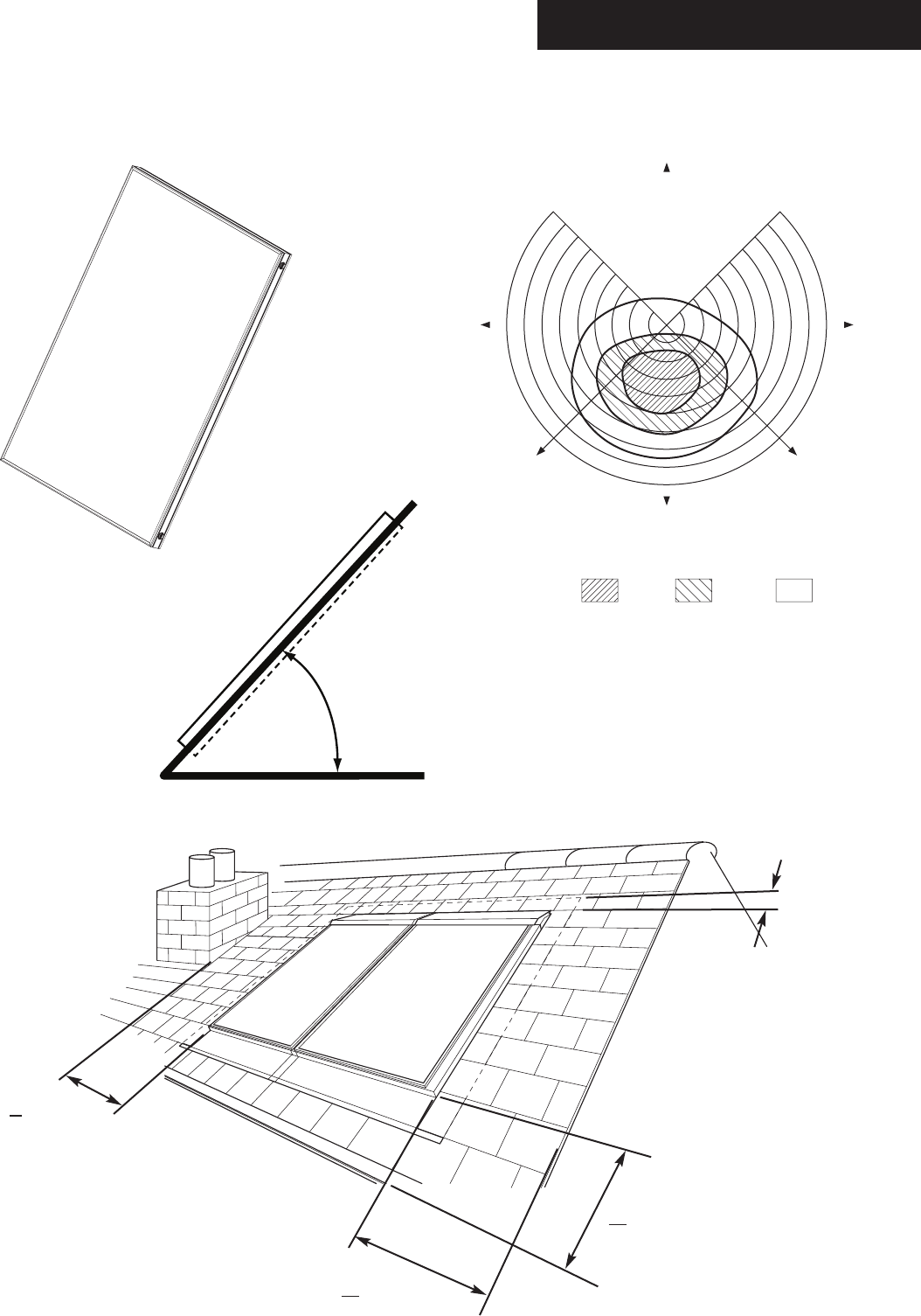
2.0 General Layout
© Baxi Heating UK Ltd 2011
10°10°
20°20°
30°30°
40°40°
50°50°
60°60°
70°70°
80°80°
90°
Angle of tilt
North
South
less than optimum by 0-5% 5-10% 10-20%
East
S.E.S.W.
West
90°
> 350mm
> 500mm
100mm
20° to 55°
> 500mm
5
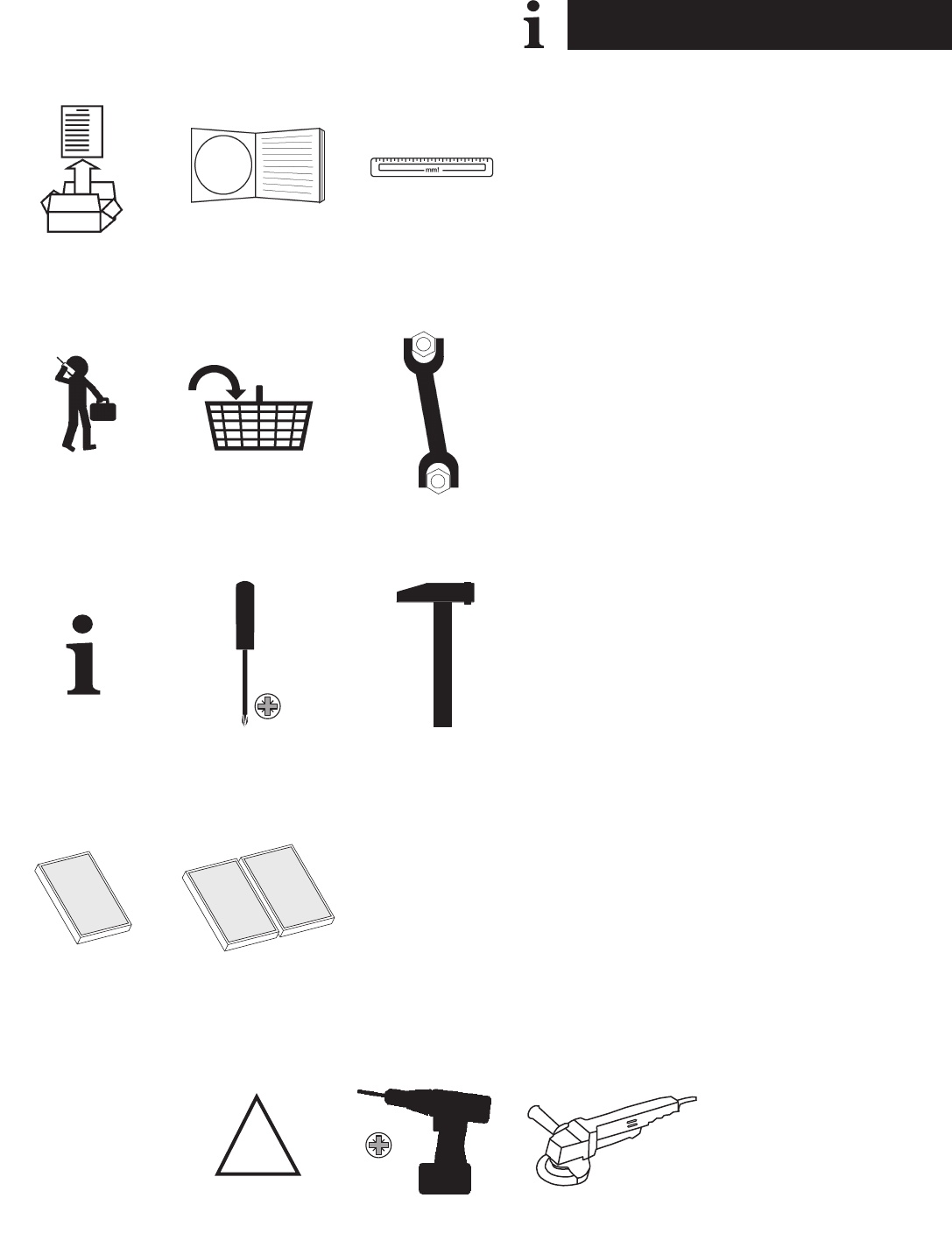
3.0 Icon Quick Reference Guide
© Baxi Heating UK Ltd 2011
3A 3B 3C
3D 3E 3F
3G 3H 3J
3K 3L 3M
3N 3P 3Q
R/H
L/H
13mm
!
3A - Contents
3B - Page Reference Number
3C - Measure
3D - Specialist Advice Required
3E - Materials to be Provided by Installer
3F - Spanner Tight
3G - Information or Advice
3H - Screwdriver
3J - Hammer
3K - 1 Collector
3L - 2 Collectors
3M - Right Hand Side
3N - Left Hand Side
3P - Caution
3Q - Drill / Driver
3R - Tile Cutter
3R
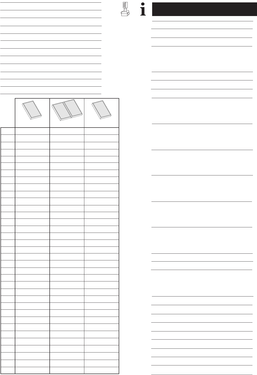
6
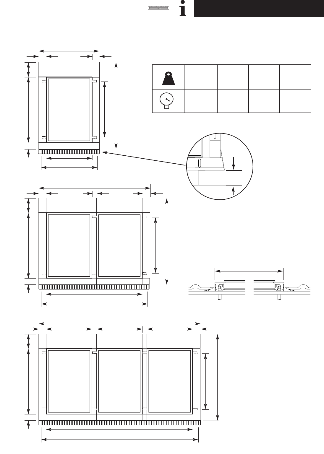
4.0 Dimensions
© Baxi Heating UK Ltd 2011
kg
10
bar
0!
SOL 200
35kg
10bar
36kg
10bar
48kg
10bar
49kg
10bar
SOL 200H SOL 250 SOL 250H
150 /
300mm
a
cd
b
e
f
a
bcd
e
f
a
b c d
e
f
130
390
174.5 40 40 174.5
130
390
174.5 40 174.5
174.5 174.5
130
390
f
7
4.0 Dimensions
© Baxi Heating UK Ltd 2011
a
b
c
d
e
f
a
b
c
d
e
f
a
b
c
d
e
f
a
b
c
d
e
f
a
b
c
d
e
f
1496
1753
1610
2272
1147
1289
2683
1753
1610
2272
2334
2476
3870
1753
1610
2272
3521
3663
5057
1753
1610
2272
4708
4850
6244
1753
1610
2272
5895
6037
Sol 200 Sol 200H Sol 250 Sol 250H
2101
1147
1004
1666
1753
1895
3895
1147
1004
1666
3546
3688
5688
1147
1004
1666
5339
5481
7481
1147
1004
1666
7132
7274
9274
1147
1004
1666
8925
9067
1496
2187
2044
2706
1147
1289
2683
2187
2044
2706
2334
2476
3870
2187
2044
2706
3521
3663
5057
2187
2044
2706
4708
4850
6244
2187
2044
2706
5895
6037
2536
1147
1004
1666
2187
2329
4763
1147
1004
1666
4414
4556
6990
1147
1004
1666
6641
6783
9217
1147
1004
1666
8868
9010
11444
1147
1004
1666
11095
11237
1
2
3
4
5
a
b
c
d
e
f
a
b
c
d
e
f
a
b
c
d
e
f
a
b
c
d
e
f
a
b
c
d
e
f
7431
1753
1610
2272
7082
7224
8618
1753
1610
2272
8269
8411
9805
1753
1610
2272
9456
9598
10992
1753
1610
2272
10643
10785
12179
1753
1610
2272
11830
11972
Sol 200 Sol 200H Sol 250 Sol 250H
11067
1147
1004
1666
10718
10860
12860
1147
1004
1666
12511
12653
14653
1147
1004
1666
14304
14446
16446
1147
1004
1666
16097
16239
18239
1147
1004
1666
17890
18032
7431
2187
2044
2706
7082
7224
8618
2187
2044
2706
8269
8411
9805
2187
2044
2706
9456
9598
10992
2187
2044
2706
10643
10785
12179
2187
2044
2706
11830
11972
13671
1147
1004
1666
13322
13464
15898
1147
1004
1666
15549
15691
18125
1147
1004
1666
17776
17918
20352
1147
1004
1666
20003
20145
22579
1147
1004
1666
22230
22372
6
7
8
9
10
mm mm
8
5.0 Health and Safety
© Baxi Heating UK Ltd 2011
!
9
5.0 Health and Safety
© Baxi Heating UK Ltd 2011
!
10
5.0 Health and Safety
© Baxi Heating UK Ltd 2011
!
!
kg
!
!
!
11
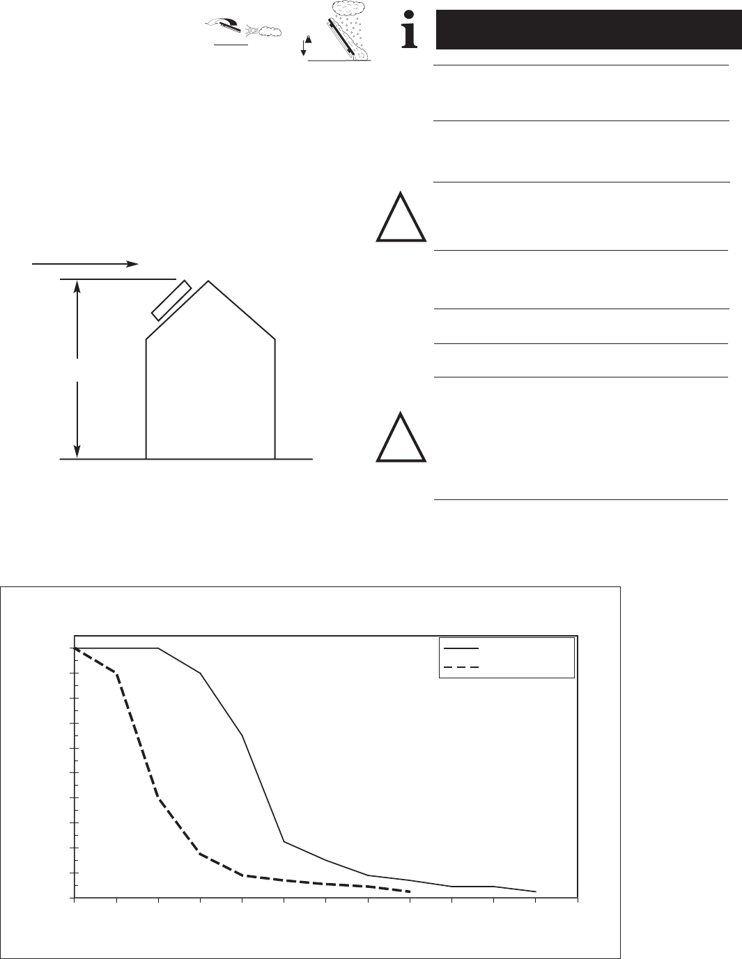
6.0 Snow and Wind Load
© Baxi Heating UK Ltd 2011
EN1991-1-3:2003
- Standard - Snow Loading
SOL 200/200H/250/250H
- Design limit snow load on the ground = 2.8kN/m2
NOTE: This limit may be reduced for installations where
abutments create additional risks of drifting or falling snow.
WARNING: The maximum wind load to be borne by the
mounting structure depends on the height and geographical area
of the site among other factors. This structure must be installed in
accordance with the provisions of the EN1991 standard. Consult
a structural engineer if in doubt.
Limit for in-roof installation for given site basic wind speed
(For c
o
=1)
0
20
40
60
80
100
120
140
160
180
200
21 22 23 24 25 26 27 28 29 30 31 32 33
Y
SOL200/200H
SOL250/250H
X
EN1991-1-4:2005
- Standard - Wind Loading
X - Basic wind speed (Vb, o) in m/s
Y - Maximum height above ground for installation (m)
!
kg
!
Y
X!
!
12
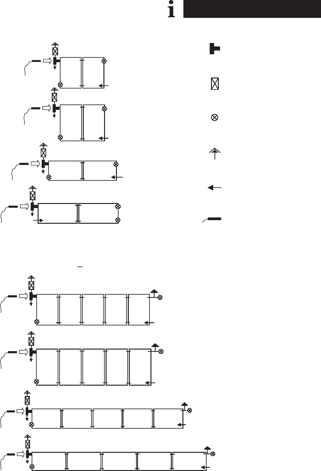
7.0 Optimum Pipework Assembly
© Baxi Heating UK Ltd 2011
SOL 200
SOL 250
SOL 200H
SOL 250H
SOL 200H
SOL 250H
SOL 200
SOL 250
- Tee Piece
- Valve
- Plug
- Air Vent (Optional)
- Flow
- Sensor
n < 5
n > 5
13
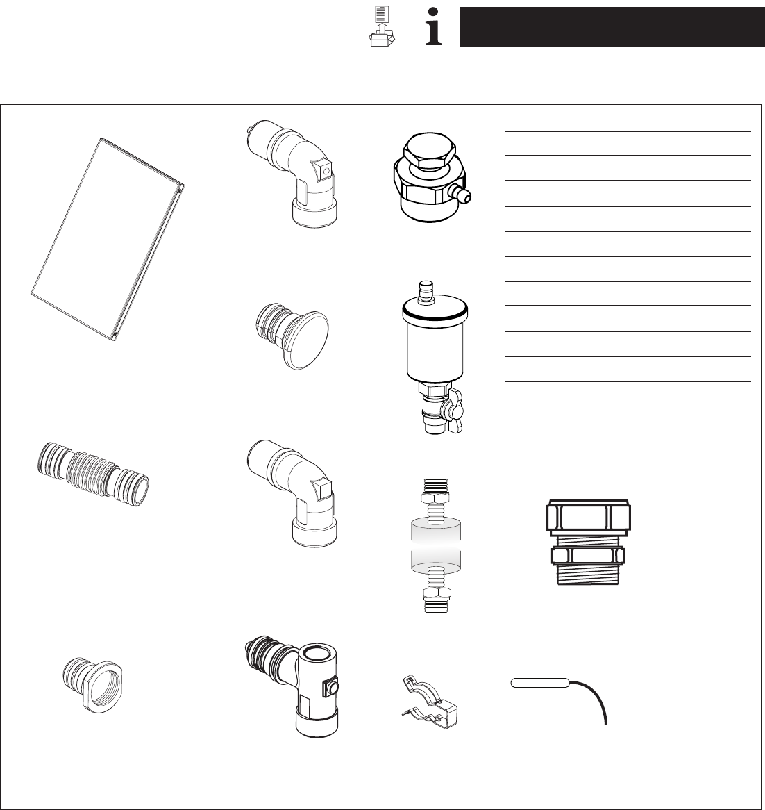
8.0 Kit Contents and Components
© Baxi Heating UK Ltd 2011
AA3 - Collector
BB3 - Sensor Elbow
CC3 - End Cap
DD3 - Joining Piece
EE3 - Elbow
FF3 - Plug for Manual Air Vent
GG3 - Tee Piece
HH3 - Clip
JJ3 - Manual Vent (Optional)
KK3 - Auto Air Vent (Optional)
LL3 - Sensor
MM3 - 2m Pipe Kit
NN3 - Straight Connector with fittings
AA3
DD3
BB3
CC3
EE3
GG3
FF3 HH3
JJ3
KK3
MM3
LL3
NN3
14
8.0 Kit Contents and Components
© Baxi Heating UK Ltd 2011
LL KK
AA YY
DD
NN
PP
OO
FF
BB CC
EE
GG MM
QQ ZZ
V V
UU
TT
RR
WW XX
SS
SOL 250 only
HB
HA
HH
SOL 250 only
JB
JA
JJ
15
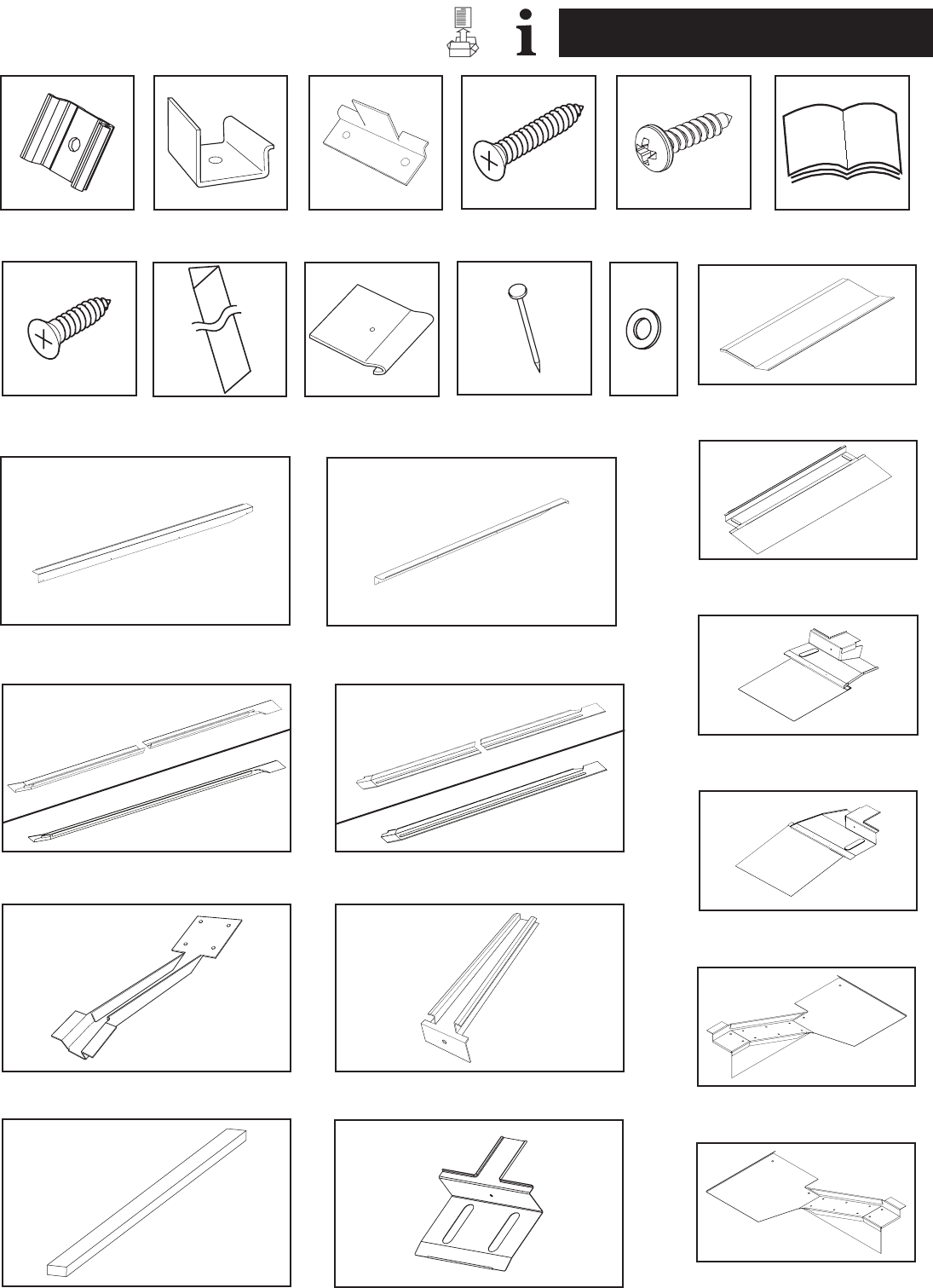
8.0 Kit Contents and Components
© Baxi Heating UK Ltd 2011
AA - Intermediate Clamp
BB - Side Clamp
CC - Bottom Bracket
DD - Top Panel Portrait SOL200/250
- Top Panel Landscape SOL200H
- Top Panel Landscape SOL250H
EE - Top Corner L/H
FF - Top Corner R/H
GG - Top Infill Section
HH - Side Lower L/H Portrait SOL200
- Side Lower L/H Landscape SOL200H/250H
HA/HB - Side Lower L/H Portrait SOL250
JJ - Side Lower R/H Portrait SOL200
- Side Lower R/H Landscape SOL200H/250H
JA/JB - Side Lower R/H Portrait SOL250
KK - Side Cover L/H Portrait SOL200
- Side Cover L/H Portrait SOL250
- Side Cover L/H Landscape SOL200H/250H
LL - Side Cover R/H Portrait SOL200
- Side Cover R/H Portrait SOL250
- Side Cover R/H Landscape SOL200H/250H
MM - Middle Infill Section Portrait SOL200
- Middle Infill Section Portrait SOL250
- Middle Infill Section Landscape SOL200H/250H
NN - Bottom Section Portrait SOL200/250
- Bottom Section Landscape SOL200H
- Bottom Section Landscape SOL250H
OO - Bottom Corner L/H
PP - Bottom Corner R/H
QQ - Batten 25 x 75 x 1200 (mm) SOL200/250
- Batten 25 x 75 x 1800 (mm) SOL200H
- Batten 25 x 75 x 2200 (mm) SOL250H
RR - Wood Screw (75mm)
SS - Wood Screw (25mm)
TT - Coloured Waterproof Washer
UU - Coloured Self Drilling Screw
VV - Nail
WW - Flashing Kit Foam (2m)
XX - Side Flashing Fixing Tab
YY - Instructions
ZZ - Bottom Infill Piece
A- One SOL200 Portrait Collector Kit
B- One SOL250 Portrait Collector Kit
C- One SOL200H Landscape Collector Kit
D- One SOL250H Landscape Collector Kit
E- Two SOL200 Portrait Collector Kit
F- Two SOL250 Portrait Collector Kit
G- Two SOL200H Landscape Collector Kit
H- Two SOL250H Landscape Collector Kit
J- SOL200 + 1 Extension Portrait Kit
K- SOL250 + 1 Extension Portrait Kit
L- SOL200H + 1 Extension Landscape Kit
M- SOL250H + 1 Extension Landscape Kit
A
-
6
2
1
1
1
-
1
1
1
1
-
1
1
1
5
15
16
14
14
8
4
8
1
-
2
-
1
1
AA
BB
CC
DD
EE
FF
GG
HH
HA
HB
JJ
KK
LL
MM
NN
OO
PP
QQ
RR
SS
TT
UU
V V
WW
XX
YY
ZZ
CC3
DD3
EE3
FF3
GG3
HH3
B
-
6
2
1
1
1
-
-
-
1
1
-
1
1
1
5
15
16
14
14
8
4
8
1
-
2
-
1
1
C
-
6
2
1
1
1
-
1
1
1
1
-
1
1
1
5
15
16
14
14
8
3
8
1
-
2
-
1
1
D
-
6
2
1
1
1
-
1
1
1
1
-
1
1
1
10
20
16
14
14
8
4
8
1
-
2
-
1
1
E
3
6
3
2
1
1
1
1
1
1
1
1
2
1
1
10
30
24
19
19
8
4
8
1
1
2
2
1
1
F
3
6
3
2
1
1
1
-
-
1
1
1
2
1
1
10
30
24
19
19
8
5
8
1
1
2
2
1
1
G
3
6
3
2
1
1
1
1
1
1
1
1
2
1
1
10
30
24
19
19
8
4
8
1
1
2
2
1
1
H
3
6
3
2
1
1
1
1
1
1
1
1
2
1
1
20
40
24
19
19
8
5
8
1
1
2
2
1
1
J
3
-
1
1
-
-
1
-
-
-
-
1
1
-
-
5
10
8
5
5
-
1
-
-
1
-
2
-
-
K
3
-
1
1
-
-
1
-
-
-
-
1
1
-
-
5
10
8
5
5
-
1
-
-
1
-
2
-
-
L
3
-
1
1
-
-
1
-
-
-
-
1
1
-
-
5
10
8
5
5
-
1
-
-
1
-
2
-
-
M
3
-
1
1
-
-
1
-
-
-
JA 1---1------
-
JB 1---1------
-1---1------
-1---1------
-
-
1
1
-
-
10
20
8
5
5
-
2
-
-
1
-
2
-
-
11111111- - - -
44444444- - - -
+1

16
9.0 Installation of the Collector
© Baxi Heating UK Ltd 2011
X4
Sol 200
Sol 250
Sol 200H
Sol 250 H
935mm
1185mm
585mm
585mm
X2 =
85mm
RR
QQ
6
7
Sol 200
Sol 250
Sol 200H
Sol 250 H
435mm
560mm
260mm
260mm
X1 =
Sol 200
Sol 250
Sol 200H
Sol 250 H
1435mm
1810mm
910mm
910mm
X3 =
Sol 200
Sol 250
Sol 200H
Sol 250 H
2020mm
2460mm
1415mm
1415mm
X4 =
X3
X2
X1
>a
> d
X2
85mm
X3
X4
X1
> hh >hh
QQ
= hh
=
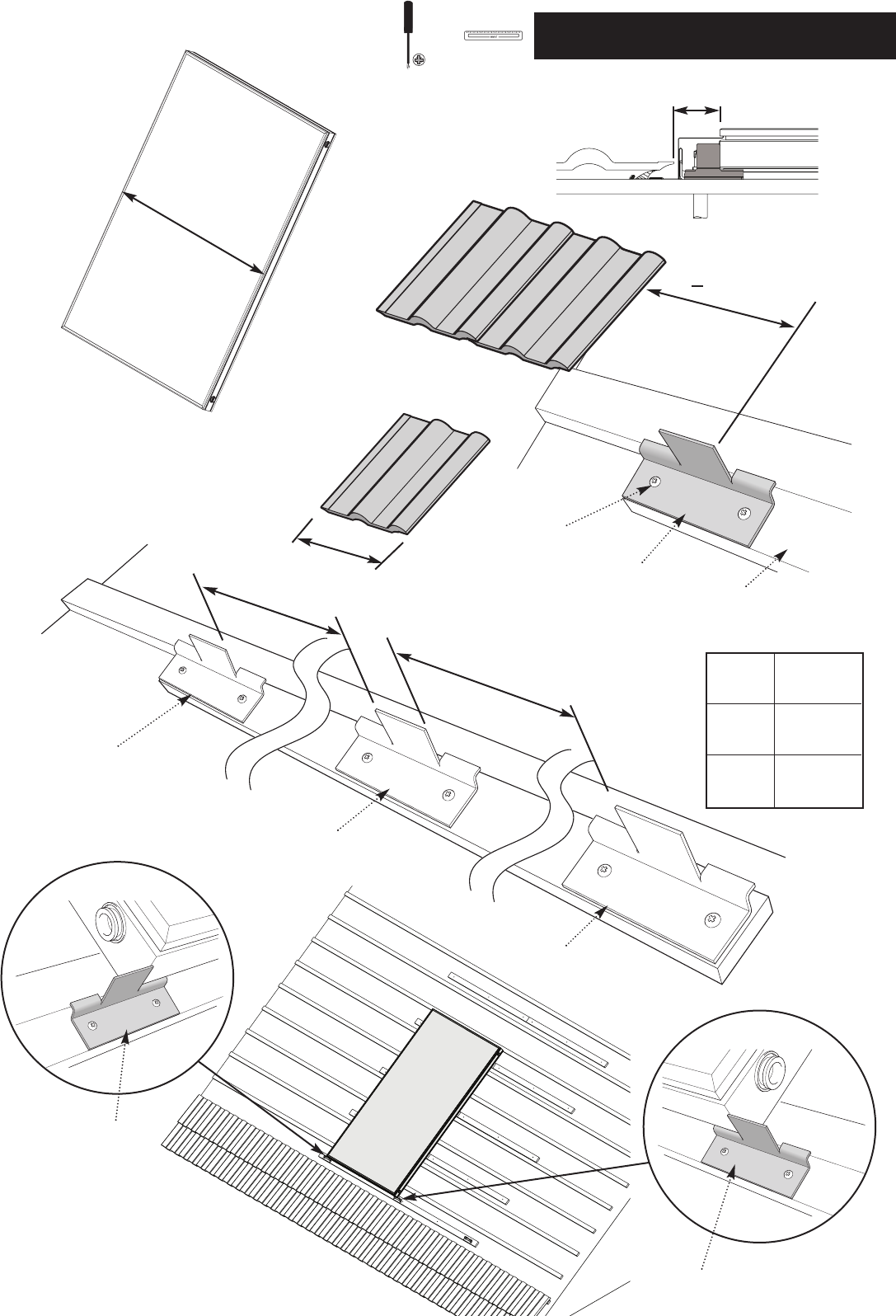
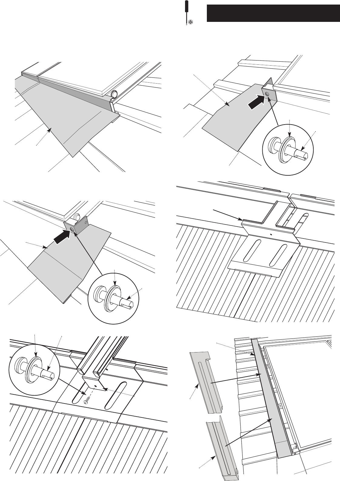
17
9.0 Installation of the Collector
© Baxi Heating UK Ltd 2011
X
CC
CC
CC
SS
Sol
200/250
Sol
200H
Sol
250H
1147mm
1753mm
2186mm
X =
> 220mm
W + 80mm
W
QQ
X
X
CC
CC
CC
80mm
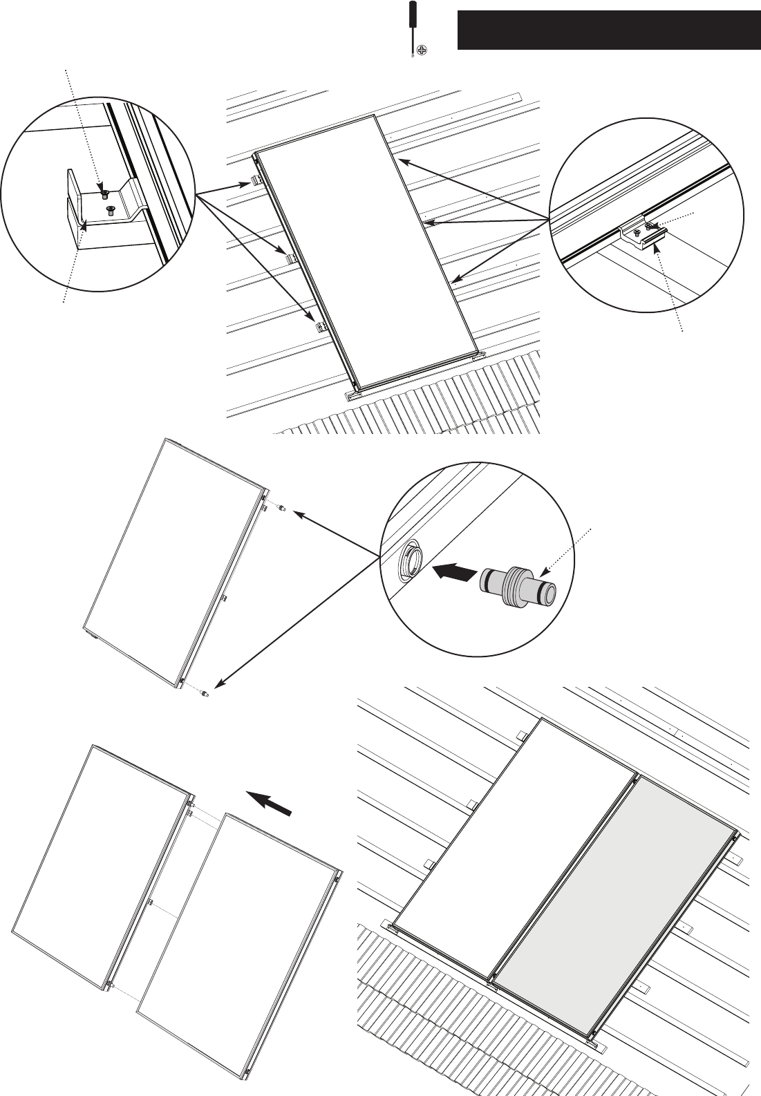
18
9.0 Installation of the Collector
© Baxi Heating UK Ltd 2011
DD3
BB
SS
AA
SS
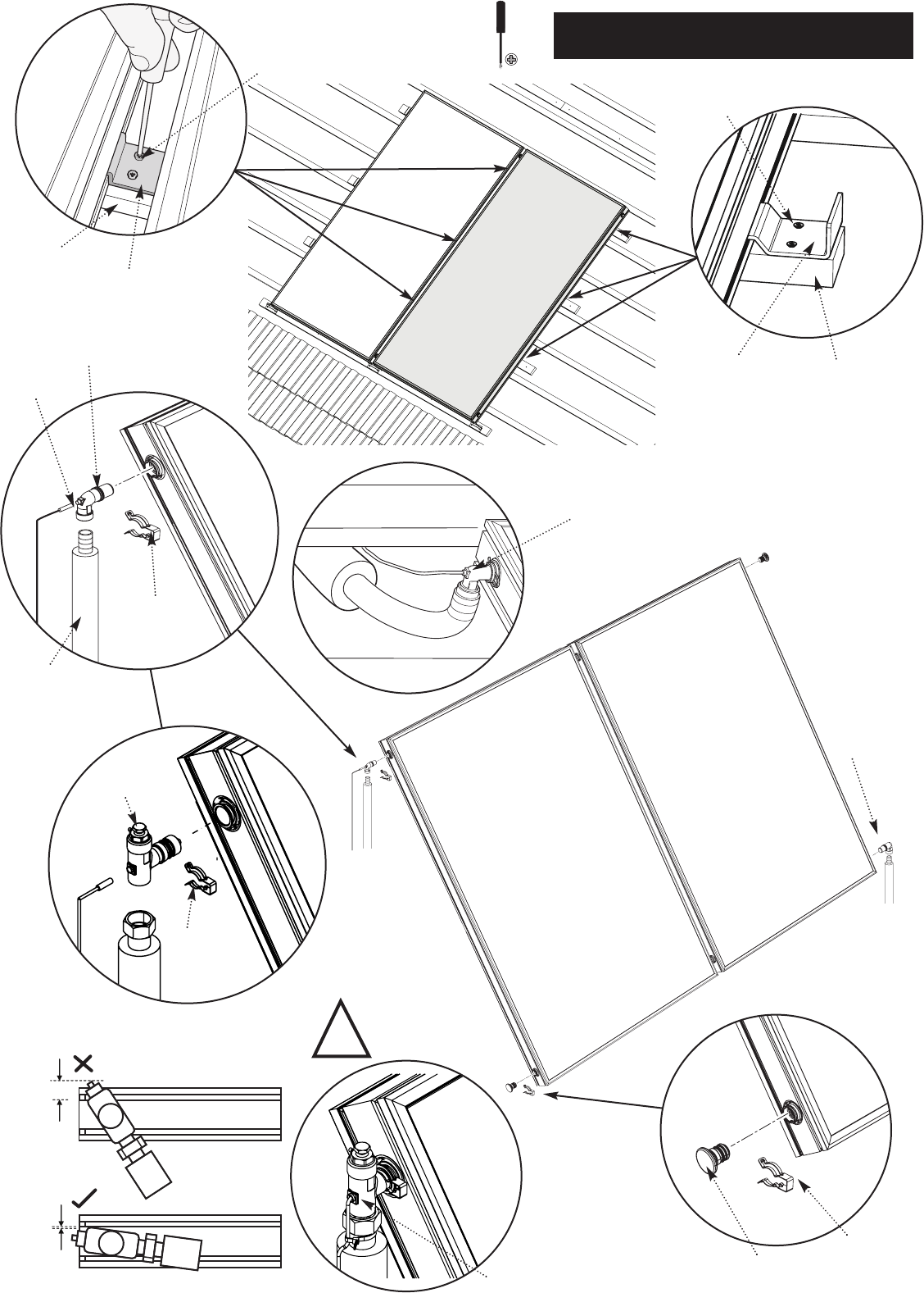
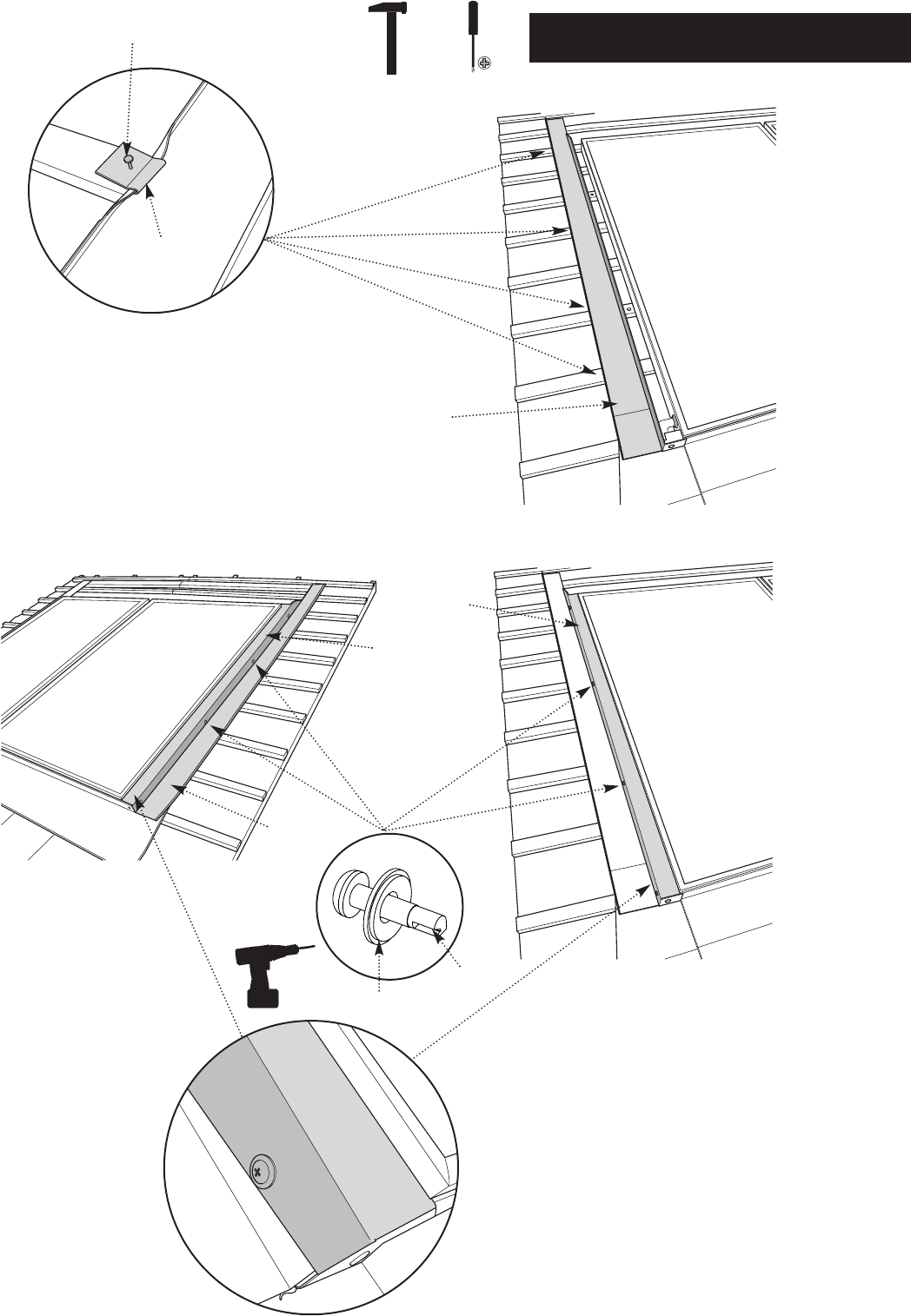
19
9.0 Installation of the Collector
© Baxi Heating UK Ltd 2011
AA
BB
BB3
CC3
EE3
HH3
HH3
SS
QQ
SS
QQ
LL3
Seal using High Temperature
UV Stable Sealant
MM3
GG3
HH3
!
Seal using High Temperature
UV Stable Sealant
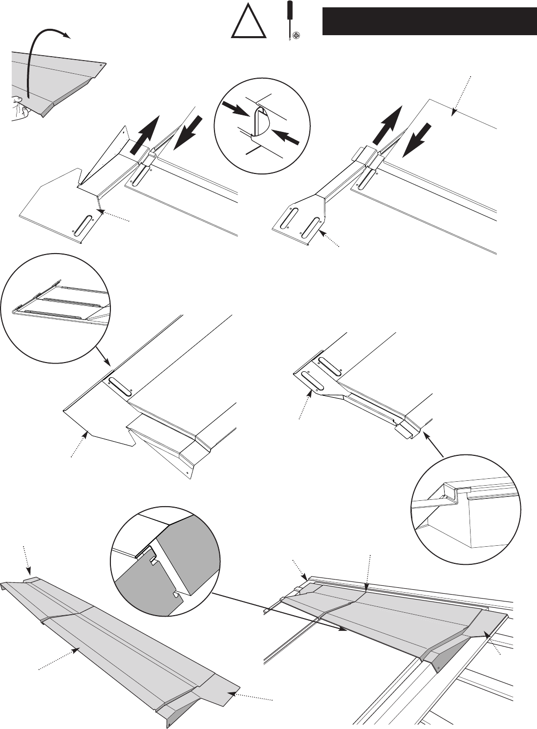
20
10.0 Fixing the Flashing
© Baxi Heating UK Ltd 2011
OO
PP
NN
HH
HA
HB
MM
ZZ
TT UU
TT
UU
TT
UU
21
10.0 Fixing the Flashing
© Baxi Heating UK Ltd 2011
V V
XX
HH
(HA)
(HB)
LL
KK
JJ
(JA)
(JB)
TT UU
22
10.0 Fixing the Flashing
© Baxi Heating UK Ltd 2011
FF
DD
GG
FF
DD
!
EE
EE
EE
GG
EE GG
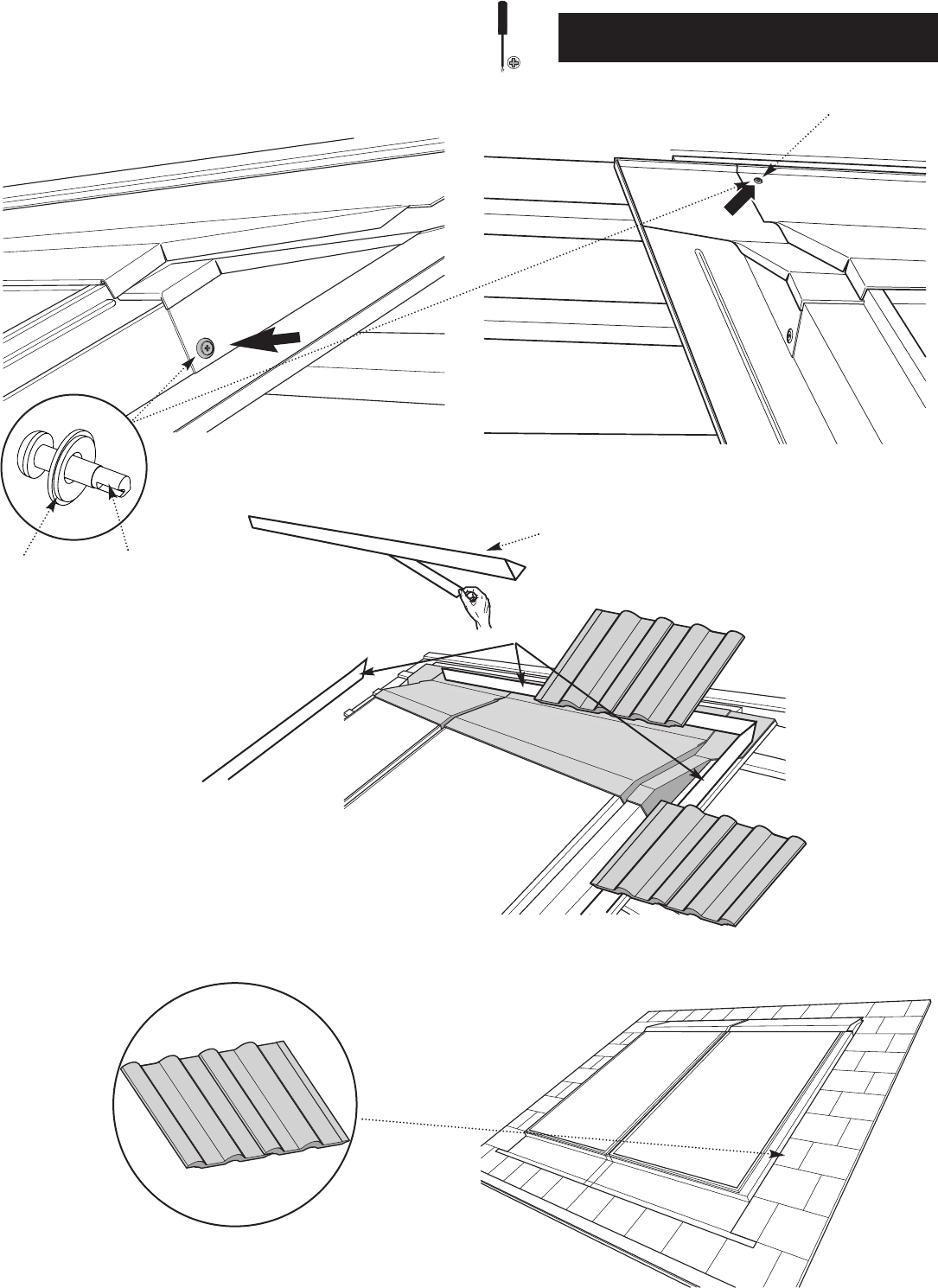
23
10.0 Fixing the Flashing
© Baxi Heating UK Ltd 2011
WW
TT - UU
TT UU

© Baxi Heating UK Ltd 2011 UK Comp No720291002 (4/11)
All descriptions and illustrations provided in this leaflet have been carefully
prepared but we reserve the right to make changes and improvements in
our products which may affect the accuracy of the information contained in
this leaflet. All goods are sold subject to our standard Conditions of Sale
which are available on request.
MULTIFIT
A Trading Division of Baxi Heating UK Ltd (3879156)
Brooks House, Coventry Road, Warwick. CV34 4LL
Technical Enquiries 0844 871 1568
Website www.bdrthermea.com
e&oe
11.0 Maintenance
It is recommended that the following checks are carried out
on an annual basis:
1) Check the collector installation for any signs of damage or
any build up of debris.
2) Check for any corrosion to the collector or the mounting
system and repair if necessary.
3) Check the tightness of the fasteners. Where fasteners
cannot be readily accessed, the overall security of the
collector installation may indicate whether problems exist.
4) Check the fittings and pipe work for any signs of fluid
leakage or damage, including the condition of the pipe
insulation, and repair if necessary. Check inside the building
for any evidence of leaks.
5) Examine the roof tiles around the collector installation for
any damage or deterioration, and repair if necessary.
6) Check for any foliage growth that may cause shading of the
collectors.
7) Where applicable, check the condition of any ballast used
to secure the system.
8) In areas where there may be a build up of dirt on the
collector, only non-abrasive cleaning materials and methods
should be used to clean the collectors and mounting
system components.
