Beacon Display Technology 19LCDC16S LCD Monitor User Manual
Shenzhen Beacon Display Technology Co., Ltd. LCD Monitor
UserManual.wiki
>
Beacon Display Technology
>
19LCDC16S User Manual
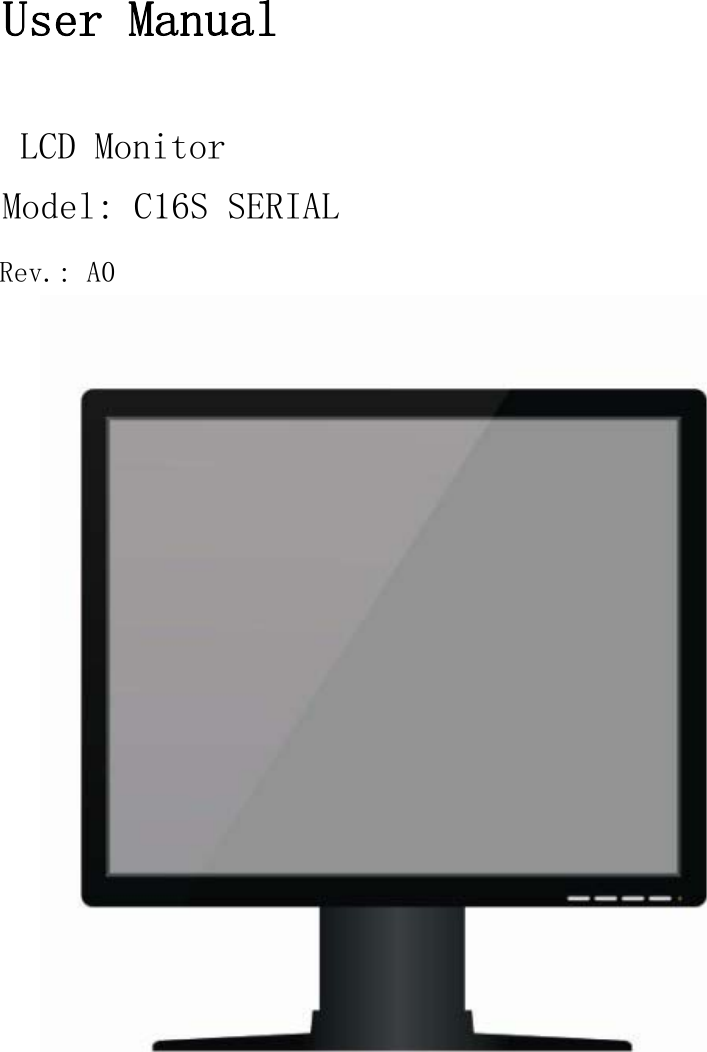
User Manual
Navigation menu
Upload a User Manual
Namespaces
Wiki Guide
HTML
PDF
Info
Views
User Manual
Discussion / Help
Navigation