Beacon Display Technology 19LCDC16S LCD Monitor User Manual
Shenzhen Beacon Display Technology Co., Ltd. LCD Monitor
User Manual
User Manual
LCD Monitor
Model: C16S SERIAL
Rev.: A0

Contents
1. Application................................................................................. 1
2. Declarations................................................................................ 1
3. Installation................................................................................ 6
4. Start-up.................................................................................... 6
4.1 Connecting the power and signal cables................................................. 7
4.1.1 Little cover (removing).......................................................... 7
4.1.2 Cable (attaching)................................................................ 8
4.1.3 Stand base (attaching)........................................................... 9
4.1.4 Mounting Use.................................................................... 10
4.2 Switching on the display.............................................................. 11
4.3 Adjusting the image geometry.......................................................... 11
4.4 Adjusting the brightness and contrast................................................. 11
4.5 Screen saver.......................................................................... 11
5. Connections................................................................................ 12
5.1 Connecting the flat panel display..................................................... 12
5.2 Connection panel...................................................................... 12
5.3 Information on additional serial interface (Service Only) ............................. 12
5.4 Analog and digital inputs (DVI,VGA,DP)................................................ 13
5.5 Power supply connection............................................................... 13
5.6 Serial interface...................................................................... 13
5.7 USB interface………………………………………………………………………………………………13
6. Adjustments................................................................................ 14
6.1 Picture adjustment.................................................................... 14
6.2 Optimum picture quality............................................................... 15
6.3 OSD menu.............................................................................. 16
6.3.1 Keys assignment and operation LED............................................... 16
6.3.2 Key functions without active OSD menu........................................... 17
6.3.3Key functions in the OSD menu.................................................... 17
6.3.4 Menu calls...................................................................... 17
6.3.5 Locking of OSD menu............................................................. 17
6.3.6 Description of the menus........................................................ 18
7. Fault diagnostics.......................................................................... 20
8. Technical data............................................................................. 20
8.1 Display............................................................................... 20
8.2 Power supply.......................................................................... 21
8.3 Electronics........................................................................... 21
8.4 Inputs/outputs........................................................................ 22
8.4.1 Analog signal input............................................................. 22
8.4.2 Digital signal input............................................................ 22
8.4.3 Serial interface................................................................ 22
8.4.4 Timing Input.................................................................... 22
8.5 Controls and connection elements...................................................... 23
8.6 Mechanical design..................................................................... 23
8.7 Climatic conditions................................................................... 24
8.8 Mechanical requirements............................................................... 24
8.9 Safety specifications................................................................. 24
8.10 Electromagnetic compatibility........................................................ 25
9. Dimensional drawings....................................................................... 25
9.1 Front , Platform and Side view........................................................ 25
10 Remarks and contact address................................................................ 25
Page 1 of 26
1. Application
This high-resolution color display with touch screen use is
specifically designed to meet the rigorous performance standards needed
for diagnostic, interventional radiology, and other medical applications.
To guarantee image integrity, features include accurate signal
conversion and a wide range of interfacing options.
Compact design -Low weight and small size with improved performance make
the color flat panel display HL1916S SERIAL preferable to conventional
CRT monitors.
Embedded LUT(Look Up Table )-This monitor is factory calibrated to
achieve Gamma2.2 compliance and Linear gray level reproduction at the
factory set point. Six different settings are stored within the display.
Screen resolution- HL1916S SERIAL is equipped with a panel with Twisted
Nematic technology. The optimal picture resolution is 1280 x 1024 pixels.
Video signals with other resolutions typical to medical engineering are
optimally zoomed in or out to the screen size.
Fast backlight stability- The luminance stabilization circuit employs
a built in photo sensor to keep the back-light lamps at a constant
luminance for consistent calibration over the life of the display and
can control the back light system automatically to extend the life of
the monitor
Multi-interface for video inputs- Support DVI-D, VGA, DisplayPort.
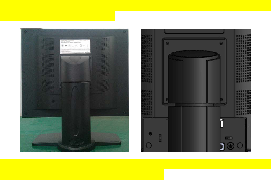
Embedded full functional stand base - The stand base is embedded inside
the monitor and can be easily removed. The stand base is up/down and tilt
adjustable.
2. Declarations
Safety precautions
WARNING:
To avoid risk of electric shock, this equipment must only be connected
to a supply mains with protective earth.
Medical Equipment
With respect to electric shock, Fire and mechanical
hazards only in accordance with ANSI/AAMI
ES60601-1:2005&CSA C22.2 No.60601-1:2008
Page 2 of 26
Appliance coupler or separable plug of is used as isolation means to
isolate the equipment from mains supply.
Accessory equipment connected to the analog and digital interfaces
must be certified according to the respective IEC/EN standards
(e.g.IEC/EN950 for data processing equipment and IEC/EN 60601-1 for
medical equipment).
Furthermore all configurations shall comply with the valid version of
the System standard IEC/EN 60601-1-1.Everybody who connects
additional equipment to the signal input connector or signal output
connector
Configures a medical system, and therefore responsible that the system
Complies with the requirements of the valid version of the system
standard IEC/EN 60601-1-1. If in doubt, consult our technical service
department or your local distributor.
Regular maintenance and calibration are recommended
Please note that liquid crystal displays such as the HL1916S SERIAL
do not have a failure rate of zero and image parameters may change over
time (e.g. luminance or discoloration). Please ensure that all
measures are taken to prevent injuries or incorrect diagnoses. Regular
maintenance and calibration are recommended.
Correct and safe operation of the flat panel displays is dependent on
proper transport, storage, installation and assembly, as well as
careful operation and maintenance. The units must only be used for
applications for which monitors are normally used. The information in
the Section "Technical data" must be observed exactly.
For the sake of safety, the following precautions must be observed:
Only use a perfect power supply cable
A damaged power supply cable may result in a fire or electric shock.
When disconnecting the power supply cable, always do so by holding the
plug.
Only use the same type of fuse
T2A/250V
Do not insert any objects into the housing
Objects inserted into the housing may result in damage to the unit or
personal injury.
Page 3 of 26
Do not place any objects on top of the units
Penetrating liquids may result in a fire or electric shock.
Connection
No contact to a patient must occur when handling the cables.
Do not hurt yourself, when moving the display
The display can be tilted backwards and forwards. Please, pay attention
not to hurt yourself, when moving the display. Fingers or small objects
may get stuck at the bottom of the display.
When moving the display up and down (height adjustment), make sure you
do not squeeze your hand or any other object. The minimum distance
between the display edge and the bottom is only 59 mm.
Caution
Incorrect installation may result in extensive damage to property.
Installation should be carried out by trained personnel
When installing your medical electrical system with our products in
an environment with patients, please observe the safety requirements
of EN 60601-1 (IEC 60601-1) for "Specifications for the safety of
medical electrical systems" in order to prevent injury to patients and
users of your systems.
Take appropriate measures to particularly ensure that discharge
currents remain below the required limits: Appropriate measures:
- Disconnecting devices for signal input or output unit
- Use of a safety transformer
- Use of additional PE conductor
Only use the signal cables and interface cables specified by the
manufacturer for the installation.
Use power cables with a PE contact. Only insert into sockets with a
PE contact.
For certain applications, the video earth can be separately connected
to the PE via the additional PE connection in the plug panel (observe
IEC 60601-1).
Close the plug panel using the provided cover , and secure using the
Page 4 of 26
screws.
Turn switch off and then remove power cord.
Mounting information: The stability of the display must be guaranteed
following mounting of the foot/holder. The immersion depth of the
mounting screws has to be 10 to 12 mm including a 3 mm VESA mounting
plate. (See also table "Mounting screws" on the following). All these
requirements are satisfied when using the original foot. All
requirements must be observed when using customer-specific mounting
solutions.
Notice for users: The plug panel closed by the cover, must not be opened
by users.
Servicing information: If housing components have to be removed for
servicing, this must not be carried out in the presence of patients,
the user, or other persons not involved with servicing.
The following applies to installations in the USA and Canada: Molded
power supply plugs must comply with the requirements for "Hospital
Grade Attachments" UL 498.
Caution
Failure to observe the warnings may result in substantial damage to
property.
Provide sufficient heat dissipation
Holes are provided at the rear of the housing. The display must be
placed or secured on a hard, level surface at least 10cm from the wall
and 15cm away from other devices. Several displays can be butt-mounted
horizontally and vertically.
The following must be observed when mounting (VESA connection):
Mounting screws
Number 4
Thread M4
Strength 12
Immersion depth Min. 10 mm; Max. 12 mm
Torque Max. 3 Nm
Please see 4.1.4 for details.

Page 5 of 26
The permissible ambient temperature range (5 °C ... 35 °C) must n o t
be violated. Do not subject device to unnecessary shocks. Take care
when transporting! Use the original packaging! The panel in particular
should be protected against shocks.
When touching the panel surface, the mechanical contact or an
electrical discharge may cause a brief disturbance in the picture
quality.
Care of unit / cleaning agents
− The front panel is extremely sensitive to mechanical damage. Avoid
all scratches, knocks etc.!
− Remove water drops immediately; extended contact with water
discolors the surface.
Clean the front panel when dirty, using a micro fiber cloth and, if
necessary, a glass cleaning agent. Only clean housing parts using a
cleaning agent for plastics.
z Note:
Do not use cleaning agents containing solvent, e.g. petroleum spirit!
Explanation of the symbols
Alternation current (AC)
Protective earth
China Rohs symbol
EC WEEE symbol
European comformity
China Compulsory Certification
T TUV approval mark
Attention: Consult the accompanying documents

Page 6 of 26
3. Installation
Provide adequate ventilation
Ventilation slots are located on the rear of the housing.
Ambient temperature
The permissible ambient temperature range must not be violated.
Minimize reflections
The display should be positioned so that reflections of lights, windows,
furniture with shiny surfaces or light-colored walls do not appear on
the screen.
Minimize mirroring
In order to reduce mirroring on the unit, ceiling lighting or reflected
light (no dazzling) should be used. Mirroring can only be eliminated
if the screen is clean and free of grease. Clean the display using a
suitable micro fiber cloth.
Change of environment
If the unit is brought into a warm environment from a cold one, water
may condense upon it. The unit should not be switched on until all the
condensed water has evaporated, including that inside the unit. This
may take several hours, depending on the conditions.
4. Start-up
Caution
In order to ensure safe operation of the equipment, close attention
must be paid to the information contained in this Instruction Manual
as well as the warnings in Section 2 "Safety precautions".
Caution Information for end customer
None of the settings must be changed on site by the user, otherwise
the guarantee is canceled. This also applies to settings made using
the HL1916S SERIAL keys. These are therefore locked for certain
applications. If settings have to be changed, please contact the
responsible servicing department.
The display is designed for individual connection to a graphics card
with a power supply of 100 or 240 Volt (TN-S system with PE conductor).
Page 7 of 26
If the display is to be used in a sequence of several displays, or if
it is not exactly known whether the graphics card standard can be output
by the display, refer to Section 5.1 "Connection of the flat panel
display".
In order to start the unit properly, the following steps should be
carried out in the given sequence.
4.1 Connecting the power and signal cables
Warning The display can be tilted backwards and forwards. Please, pay
attention not to hurt yourself, when moving the display. Fingers or
small objects may get stuck at the bottom of the display.
Caution
Use a power cable with PE conductor corresponding to the safety
requirements of the respective country of use. Note for North America:
Molded power supply plugs must comply with the requirements for
hospitals with respect to CSA Std. C22.2 No. 21 and UL 498.The power
supply and signal connections are located on the rear of the color flat
panel display.
Note
Note that the cables are already positioned when you receive the
display (power cable and DVI-D cable). The following steps are only
necessary if you need to connect/disconnect the cables of the scope
of supply.
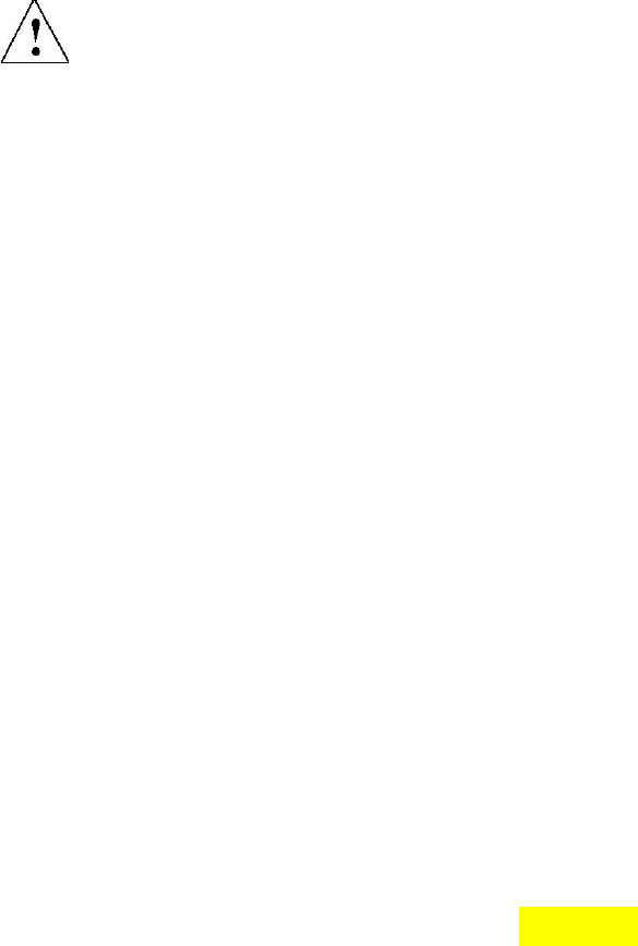
4.1.1 Little cover (removing)
Remove the one screws with a M4 Slot screwdriver (one turn
suffices).Pull down the little cover and then open the little cover
and remove it.
Page 8 of 26
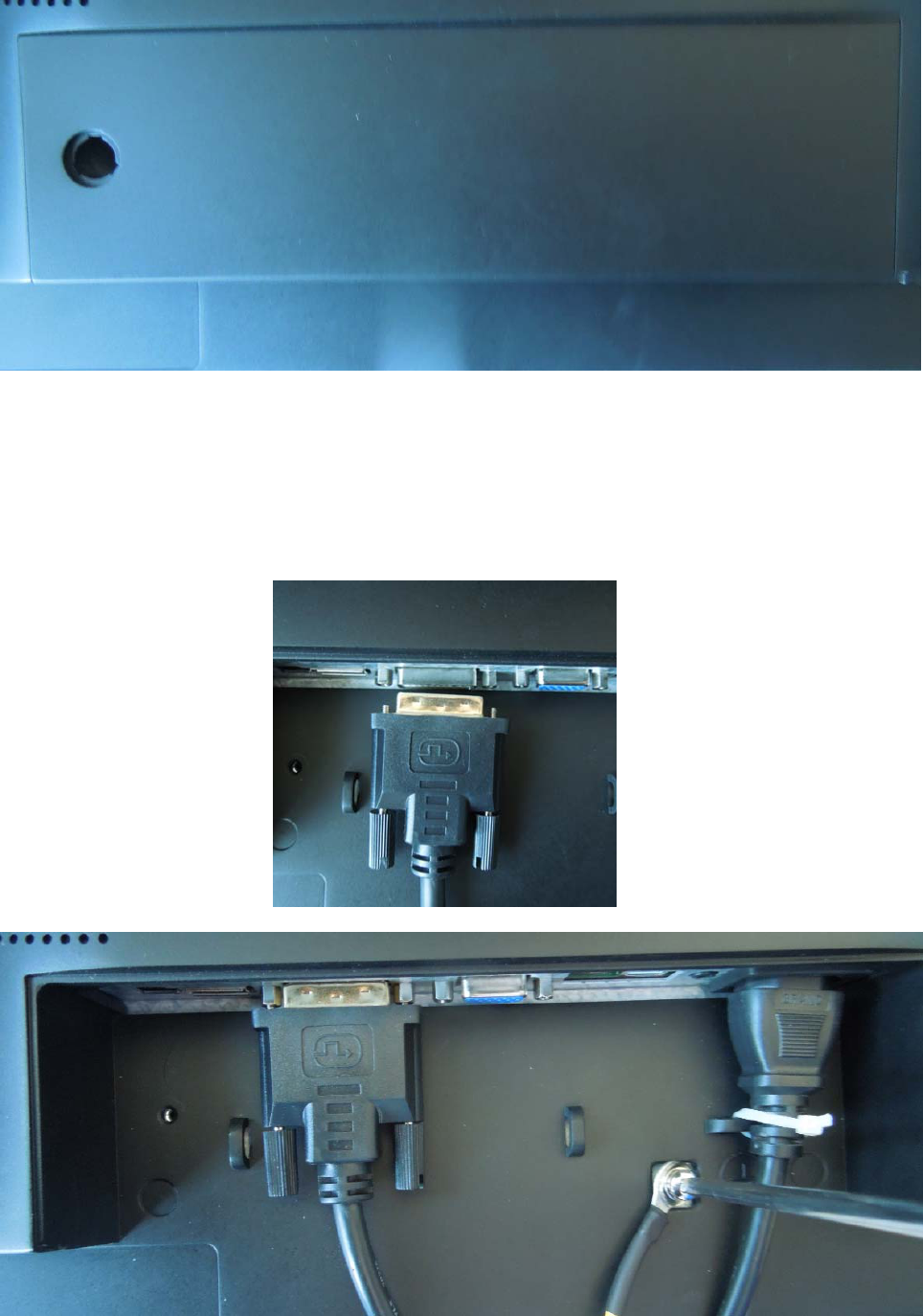
4.1.2 Cable (attaching)
Connect the cables to the display.
VGA connector: the flat panel display can be connected to the computer
system using a VGA Cable on D-sub connection for analog signal. The
Page 9 of 26
display is adapted using an OSD menu.
DVI-D connection: The connection to the computer can also be made via
the digital single link. The picture quality, noise immunity and
radiated interference of the complete system depend on the cable
quality and length.
DP connection: The connection to the computer can also be made via the
DisplayPort connection. The picture quality, noise immunity and
radiated interference of the complete system depend on the cable
quality and length.
Serial connection: you can connect the display via the RJ11 connector
to the computer for firmware updating.
4.1.3 Stand base (attaching)
Put the stand base near VESA holes of the monitor. Fasten the stand
base with four M4x12 screws.
Move the button of stand base towards the right, and lift the monitor,
and then turn the monitor by 90 degrees.
Page 10 of 26
Note: the stand base is optional.
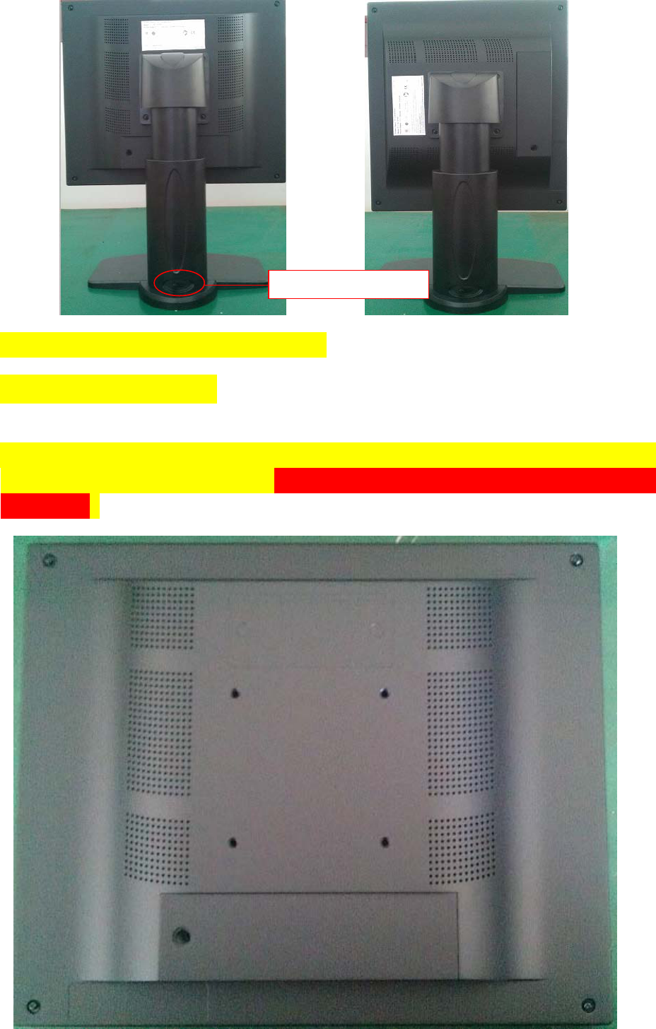
4.1.4 Mounting Use
Remove the stand base according to the contrary way in 4.1.3. Fix the
mount by mounting screws (see page 6 table Mounting Screws for
details).
Button of stand base

Page 11 of 26
4.2 Switching on the display
Switch on the flat panel display using the power switch. The operation
LED lights up (color: green, provided the timing has been recognized
– please refer to section 7 "Fault diagnostics").
4.3 Adjusting the image geometry
The display automatically recognizes the used standard, and set-up
values for each standard are preprogrammed. However, depending on the
graphics card used, it may still be necessary to align and size the
picture for the selected standard (see Section 6.1 "Picture
adjustment"). Normally auto adjust will work.
4.4 Adjusting the brightness and contrast
The brightness and contrast must be adjusted for the respective
graphics card (different output levels) in the system on site.
Note on adjustment
− Use the SMPTE test pattern.
− Adjust the brightness so that image sections with 5% and 0%
blackness still visibly contrast from one another.
− Adjust the contrast so that image sections with 95% and 100%
whiteness still visibly contrast from one another. To adapt the
luminosity to the ambient lighting, adjust the backlight brightness
(note: 180 cd/m² factory setting is then modified).
4.5 Screen saver
A screen saver function should be used in order to reduce "image
sticking" which can occur in TFT displays.
It is high risk to display a static graphic over half an hour.
Image sticking is the effect where a faint image of the previous screen
contents can still be seen after the display contents have changed.
By using a screen saver with permanently changing screen contents,
unnecessary effects of the same image are avoided.
If the keyboard is locked, contact the servicing department in order
to unlock it. The guarantee is cancelled if you unlock it yourself!
Page 12 of 26
5. Connections
5.1 Connecting the flat panel display
Note
All screening precautions contained in the corresponding EMC
guidelines must be observed. If these guidelines are not observed,
interference signals could penetrate the monitor.
Information on cable installation
Only screened cables are permitted for the signal connections.
All connectors should be of screw or locking types (as far as possible).
Signal and power cables must not be routed in the same duct.
The display must not share a power supply with motors or valves
(glitches!).
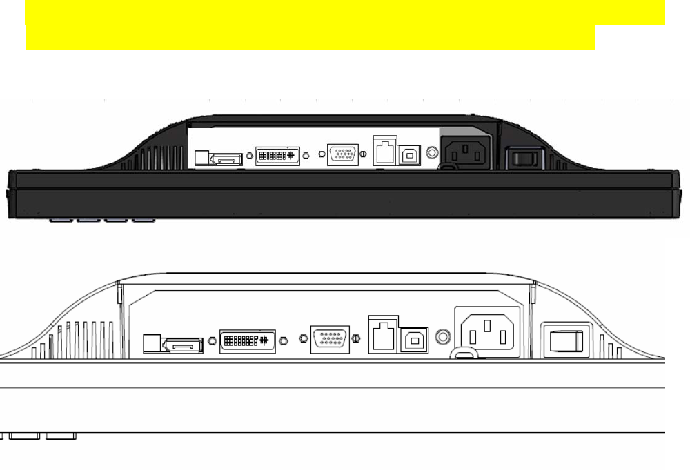
5.2 Connection panel
A connection panel for the signals and power supply is located at the
rear of the flat panel display underneath the little cover.
5.3 Information on additional serial interface (Service Only)
Serial connection: you can connect the display via the RJ11 connector
Page 13 of 26
to the computer for firmware updating and monitor test.
5.4 Analog and digital inputs (DVI,VGA,DP)
DVI socket
With DVI digital signal through DVI cable.
VGA socket
Use VGA cable for VGA input.
DP socket
With DP digital signal through DP cable.
5.5 Power supply connection
Note
Device fuses can not be exchanged outside of the repair centers.
The display power supply is connected using an appliance plug. Only
use the power cable supplied in the delivery, or a cable with PE
conductor and appliance socket to DIN 49 547, IEC 320.
Caution
A power cable with PE conductor must be used which corresponds to the
safety requirements of the respective country of use.
5.6 Serial interface
Caution
No other units may be connected to the service socket. Connection or
disconnection of a unit may only be carried out by servicing personnel
or those trained by them. A Serial Spot Meter or Universal Serial
Luminance Meter must not be connected in the presence of patients.
The display has a serial RS 232 4 pins RJ11 interface sockets to update
the SW.
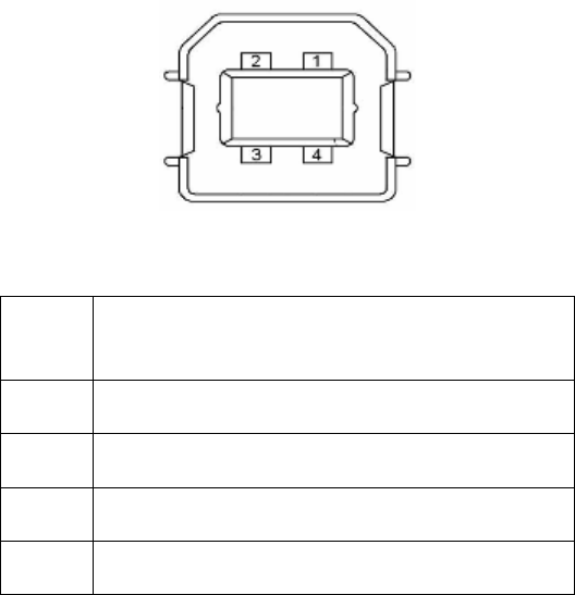
5.7 USB interface
The monitor supports touch function ,the touch screen can be used in the Windows
and the Linux.
Page 14 of 26
Figure 4 USB-B connector
Pin Signal
1 VBUS
2 D-
3 D+
4 GND
6. Adjustments
6.1 Picture adjustment
This section describes the settings for operation of the flat panel
display with a video source. The most important settings are:
Adjusting the graphics memory of the video source
As with all monitors, the flat panel display also has certain limits,
e.g. maximum resolution and vertical frequency. The graphics adapter
must be set when using the flat panel display such that the limits are
observed.
Fine adjustment of the flat panel display
Note
Fine adjustment of the flat panel display can only be carried out via
the analog port. The digital input (DVI-D,DP) does not require a fine
adjustment since the display signal is always optimum.
RGB picture sources via VGA connector supply analog signals which are
basically intended for conventional CRT monitors and which are
processed directly by them.
In contrast, the analog signals must be converted for a flat panel
display into digital signals by a video digitizer. Depending on the

Page 15 of 26
picture source, cable length and video mode (e.g. VGA, SVGA, XGA) this
conversion may cause certain deviations which cannot be corrected
fully automatically by the flat panel display. A manual fine adjustment
is therefore necessary during which the flat panel display (or, more
precisely, the video digitizer) is matched to the respective video
source. The fine adjustment comprises e.g. setting the
horizontal/vertical picture position and the picture sharpness. T hi s
can be carried out for the color flat panel display HL1916S SERIAL
using an OSD menu.
To optimize the display settings for the installed graphic board, and
to ensure all gray levels are distinguishable, we recommend to adjust
the brightness and contrast levels for and only for analog inputs. Note
that the calibration (in the Look Up Table) is not changed by these
adjustments (All the monitors are and remain factory calibrated):
Using a 100% black picture and an appropriate measurement device (a
spot meter recommended), decrease the brightness level using the OSD
controls until the measurement device displays a constant level (i.e.
the measured value no longer changes). Once this is achieved, increase
the brightness level slightly until the display is just above the
absolute lowest black level (one step is generally sufficient).
Similarly, set the white level using a 100%-white test pattern and the
measurement device. Only the contrast level should be adjusted to
ensure that the black level remains unchanged.
• Control again the black value did not change. In case it did you
need to duplicate the two previous steps until it does not change
anymore (cause: pedestal).
Increase the contrast level until the measurement device no longer
detects an increase in luminance. Once this is achieved, decrease the
contrast level slightly (1 or 2 steps is generally sufficient).
At this point, the display is configured for optimal performance with
the installed graphic board. If one is not yet satisfied with the
luminance level, the black and white levels can be further increased
by adjusting the backlight level in the OSD menu. Please note that
higher backlight level settings tend to reduce the stability of
luminance over time.
6.2 Optimum picture quality
In order to achieve an optimum picture quality, the color flat panel
display HL1916S SERIAL should be operated with a graphics resolution
Page 16 of 26
of 1280 x 1024 pixels (settings for graphics card in the PC). When
adjusting the picture position and size, ensure that the picture
appears exactly on the active surface of the display and that it is
not offset by even one pixel. For example, if the horizontal position
is offset by one step to the right, the right-hand edge of the picture
will disappear, and a black pixel column will appear at the left-hand
edge. And similarly for an offset to the left, top or bottom. If the
vertical lines are still slightly fuzzy, adjust the setting
"Frequency/phase" (see Section 6.4 "Description of the menus").
6.3 OSD menu
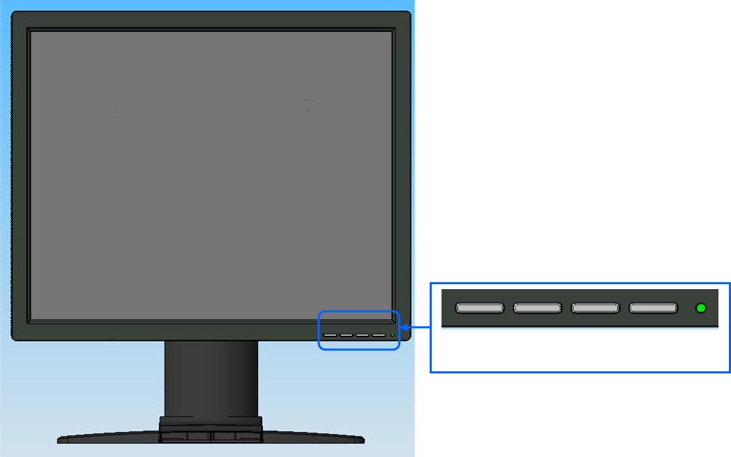
6.3.1 Keys assignment and operation LED
A “dynamic help for keypad function” is available for each menu: it
explains the role of each key depending on the OSD menu window, which
is currently active.
Menu Up Down Set LED
Page 17 of 26
6.3.2 Key functions without active OSD menu
Key Action
Menu Activate OSD
Up Define VGA port
Down Select DVI-D,DP, VGA input source
Note:
While there is no sync in VGA input, there is instruction on the OSD to indicate that how to
define the analog input as VGA input. Press and hold the ‘UP’ key for about 2 seconds, the
monitor will change the analog input between VGA.
The ‘Down’ key function is used to select input source and is enabled only when OSD menu
is locked. This function can be enabled or disabled through OSD selection. This choice is
in case all the signal sources are available. If not, the monitor will auto search DVI-D,
DP and VGA.
6.3.3Key functions in the OSD menu
Key(s) Situation Action
Menu Always Jump to next line
Up Slide controller Increase value
Command "Enter key"
Down Slide controller Decrease value
Set Sub-menu Return to previous menu
6.3.4 Menu calls
Press the “Menu” key while the OSD is active, the function icon will
jump to next line. Pressing the “Up” key, the coordinate submenu will
be selected. Press “Set” key to return to the main menu while in the
submenu state.
6.3.5 Locking of OSD menu
Keys Action
1x Set key,
then 3x Up key
Lock or unlock OSD
Page 18 of 26
6.3.6 Description of the menus
Main Menu Function Adjustment range Description
Brightness 0…100
Set brightness.
Adapting the image quality of darker
picture areas. The center point is in
50 position.
Note:
The brightness settings are
already optimized for digital signals.
Manual changes to these values are not
recommended, as this can result in an
impairment of picture quality (loss of
grayscales).
Contrast 0…100
Adjustment of contrast.
This allows the brighter area to be
seen more distinctly. The center point
is in 50 position.
Note: for DVI-D signals the
Contrast setting is optimized.
Manual changes are not recommended.
Backlight 0…100 It is used to adjust the Brightness of
the monitor.
Performance
Color
Color1
Color2
Color3
User
R G B Gain
R G B Bias
Color 1, Color 2, Color 3 are three
fixed color temperature and can not be
changed. User temperature can be
adjustable and saved.
H Position
(Analog only)
0…255 Shift picture in horizontal direction
V Position
(Analog only)
0…255 Shift picture in vertical direction
Frequency
(Analog only)
0…100 Adjust the frequency and phase of the
input signal.
Hsync Phase
(Analog only)
0…63 Source clock phase
PhaseR
(Analog only)
R ADC clock phase
0…7
PhaseG
(Analog only)
G ADC clock phase
0…7
PhaseB
(Analog only)
B ADC clock phase
0…7
For compensate R,G,B phase for analog
long cable use.
Display
Settings
Sharpness Interpolation
filter -5 to 5
One of the 11 filters can be selected
for the sharpness setting to reduce
scaling artifacts. Interpolation
filters depend on the input
resolution. Digital signals which is
used with 1280X1024 resolution can not
be adjusted since each pixel is
controlled by its own pulse. Other
Page 19 of 26
digital signals which is lower than
1280 x 1024 can be adjusted. Analog
signals can be adjusted in all
supported resolution.
Negative figure is adjusted to get
softer image and positive figure is
adjusted to get sharper image. The
user should individually adjust the
filter depending on the application.
Input
Source
DVI-D
DP
VGA
Select the active input source
priority.
If you call this OSD menu, the current
source is displayed. If current source
is inactive (NO sync) and, it will auto
search other port.
Auto-Color ON / OFF Automatically get input signal
match with the monitor
Auto-Configure ON / OFF Automatically adjust the image display
settings.
Auto Adjust
(Analog only)
Execute The selected auto functions are
executed.
Note: The quality of the function
depends on the applied picture
contents. To get better effect it is
recommended to apply full screen
picture and including white and dark
contents.
Horizontal
position
0 … 255
Adjustment of OSD horizontal position
Vertical
position
0 … 255
Adjustment of OSD vertical
position
Background 0 … 12 Select the OSD background transparency
LED ON/OFF
Setting the status of the operation
LED.
English
OSD Settings
Language
中文
Use the "Language" menu to select the
language of the OSD menu.
English is the default.
While in the English menu state the ”
中文” font means to select to Chinese
menu. And while in Chinese menu state
the “English” font means to select to
English.
Information Firmware version
OSD version
Config version
Power saving
Input Source
LUT
Working hours
Current display status can be
informed。
Service Level 2 Settings in this menu must only be carried out by service person*
Page 20 of 26
Exit Reject changes
Accept changes
Quit OSD
Check box for save or reject the
changes when
Quit OSD menu .
7. Fault diagnostics
Fault Cause Remedy
Broken fuse Inform servicing department No picture appears on
the display,
operation LED off Power cable not
inserted or
incorrectly inserted
Insert power cable
No video signal Check video cable No picture appears on
the display,
operation LED green
blinking
Video source not
supplying a signal
Check video source
Fuzzy picture,
interference in
vertical lines
Scanning frequency
or phase incorrectly
set
Adjust frequency and phase
Loose plugs Plug cables in properly and secure them Other faults –LED
orange blinking
Faulty cable Replace cable
Other faults:
“Temp. High” on
screen
Temperature shutdown
value has been
reached
Display will be automatically shut down
after a certain time (and turn on again
when the temperature decreases enough
again)
Other information available from the 2-colors LED
LED Display status
LED orange blinking No error, stand-by has been activated
LED green Video signal has been recognized, no error
8. Technical data
All technical data are valid after a warming-up period of 2 hours.
8.1 Display
Type TFT, color active matrix
Display area 376.32m x 301.06 mm
Page 21 of 26
Picture diagonal 19" or 48 cm
Native resolution 1280 x 1024 (full-screen format)
Pixel organization 3 vertical sub pixels
Pixel pitch 0.294 mm x 0.294 mm
Contrast ratio Typically 900:1
Horizontal viewing
angle
Typically ± 85° (CR≥10)
Vertical viewing angle Typically ± 80° (CR≥10)
Backlight LED
Brightness Max backlight: brightness MIN 260 cd/m² .
Factory setting: 200 cd/m²(with touch screen)
Lifetime of backlight 50,000 hours typically for LED
(applies to an ambient temperature for the backlight of 25°C)
8.2 Power supply
Input Voltage AC100-240V± 20%, 50 / 60Hz; <0.9A
Normal operation <50W
Power
Consumption Power saving <5W
Power Supply
Input Connector 3P IEC Type
8.3 Electronics
Multi-standard
technology
Video modes with resolutions less than 1280 x 1024 can be expanded
to the TFT resolution, and thus utilize the full display area (like
multi-sync CRTs).
In the same way, resolutions higher than 1280 x 1024 can be reduced
and then displayed. (Caution: depending if the timing is frame
buffered or frame sync, image information might get lost; the gray
levels - the color depth for color images - will also be reduced
and might be visible)
Timing recognition H frequency, V frequency
Page 22 of 26
8.4 Inputs/outputs
8.4.1 Analog signal input
VGA input Via VGA socket, single link
8.4.2 Digital signal input
DVI-D input Via DVI socket , single link
DP input Via DP socket
DDC Via DVI
8.4.3 Serial interface
RS232 Via RJ11 connector
8.4.4 Timing Input
Item SPEC
Frequency Horizontal: 31 ~ 82kHz
Vertical: 56 ~ 75Hz
Pixel clock 25—140 MHz
Video Bandwidth ≥ 165M Hz
Video Input Analog 0.7Vpp
Input Impedance: 75 Ohm
Sync Signal Input Separate Sync, Composite Sync on Hs, TTL/LVTTL
(N or P)
Analog
VGA
VGA EDID datum EDID via VGA I²C bus
SOG Via VGA connector
Analog R,G, B: 0.7Vpp
Input Impedance: 75 Ohm
Sync on Green: 0.2-0.3V
CVS Signal Via VGA connector
(monochrome use)
Video Level: 0.6---0.9V
Input Impedance: 75 Ohm
Sync level: 0.2---0.3V
Page 23 of 26
DVI-Digital
Single link
TMDS: 600mV for each differential line Input
Impedance: 50 ohm
DVI
Digital DVI EDID datum EDID via DVI I2C bus
Display Port 1.1
Receiver
4 main Lanes
Display Port: 600mV for each differential line
Impedance: 100 ohm per differential pair
Display
Port
DP EDID datum EDID via AUX channel
8.5 Controls and connection elements
Front Side Four keys for OSD menu, operation-LED
Rear • Power switch
•Power supply connection
• DVI socket
• DP socket
• VGA socket
• RS 232 sockets 4 pins RJ11
8.6 Mechanical design
Item Set
Width 416.5mm
Depth 179mm
Height 386.7 mm
Tilt Up & Down -5—88 degrees
Housing components Plastic
Visible screen
surface Approx. 376mm×301mm
Ventilation slots In rear panel
Degree of protection IPX0 to DIN40050
Cover color Black/white(Optional)
Mounting At rear VESA 100 x 100 mm
Net weight Approximate5.5 kg (With stand)
Page 24 of 26
8.7 Climatic conditions
Operation
Ambient temperature range +5 -- +35℃
Temperature gradient Max. 7℃/h , no condensation
Relative Humidity 15%-85%
Atmospheric pressure 70 – 106 kPa
Transport and storage (packed)
Ambient temperature range -20 -- +60℃
Temperature gradient Max. 10℃/h, no condensation
Relative Humidity 10%-90%
Atmospheric pressure 70 – 106 kPa
8.8 Mechanical requirements
Operation
Vibration According to EN 60068-2-6
10 ... 58 Hz with ± 0.075 mm deflection
58 ... 500 Hz at 10 m/s²
Shock According to EN 60068-2-27 (single shock)
150 m/s², 6 ms
No permanent shock allowed in operating conditions
Packed unit
According to 2M2 EN60721-3-2
8.9 Safety specifications
Safety standards EN60601-1、IEC60601-1、ANSI/AAMI ES60601-1:2005&CSA C22.2
No.60601-1:2008
Approvals cTUVus、CCC、CB (NCB Lab.)
Protection class Protection class I
Degree of protection
to DIN 40050
IP X0
Page 25 of 26
Type B/BF/CF applied
part No Applied Part
Category AP/APG
equipment No AP/APG
Conformity GAMMA2.2
8.10 Electromagnetic compatibility
IEC60601-1-2 Class B
FCC Part15 class B
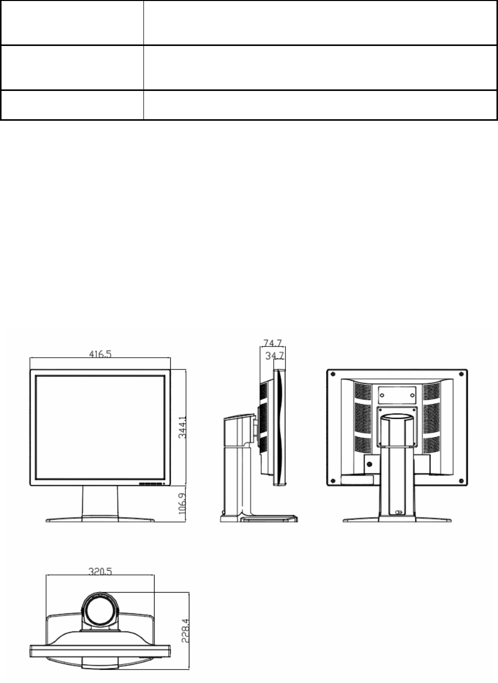
9. Dimensional drawings
All dimensions in mm.
9.1 Front, Platform and Side view
10 Remarks and contact address
Invalidity of guarantee
All unauthorized electrical or mechanical alterations on or in the unit

Page 26 of 26
result in loss of the guarantee.
Information on the Instruction Manual
For clarity reasons, this Instruction Manual does not contain all
detailed information on this product. Your attention is additionally
drawn to the fact that the contents of this Instruction Manual are not
part of a previous or existing agreement, commitment or statutory right
and do not change the latter.
Guarantee
All commitments on the part of Torch-Bigtide are contained in the
respective sales contract which also contains the complete and solely
applicable warranty conditions. These warranty conditions in the
contract are neither extended nor limited by the contents of this
Instruction Manual.
Repairs
Please contact your distributor from whom you originally purchased the
product.
Environmental protection
When disposing of the device, the requirements and laws in the respective
country must be observed.
Contact Information
Shenzhen Beacon Display Technology Co.,Ltd.
Room201, Incubator Building, CASTD, High-tech South 1st Street, Nanshan
District, Shenzhen 518057, China
Tel: 86-24-26995355
FCC Statement:
This device complies with part 15 of the FCC Rules. Operation is subject to the following
two conditions: (1) This device may not cause harmful interference, and (2) this device
must accept any interference received, including interference that may cause undesired
operation.
This equipment has been tested and found to comply with the limits for a Class B digital
device, pursuant to part 15 of the FCC Rules. These limits are designed to provide
reasonable protection against harmful interference in a residential installation. This
equipment generates, uses and can radiate radio frequency energy and, if not installed
and used in accordance with the instructions, may cause harmful interference to radio
communications. However, there is no guarantee that interference will not occur in a
particular installation. If this equipment does cause harmful interference to radio or
television reception, which can be determined by turning the equipment off and on, the
user is encouraged to try to correct the interference by one or more of the following
measures:
—Reorient or relocate the receiving antenna.
—Increase the separation between the equipment and receiver.
—Connect the equipment into an outlet on a circuit different from that to which the
receiver is connected.
—Consult the dealer or an experienced radio/TV technician for help.
Caution: Any changes or modifications not expressly approved by the party responsible
for compliance could void the user's authority to operate the equipment.