Beacon Display Technology C22WTC22WPC22W LCD Monitor User Manual
Shenzhen Beacon Display Technology Co., Ltd. LCD Monitor
UserManual.wiki
>
Beacon Display Technology
>
C22WTC22WPC22W User Manual
User Manual
Navigation menu
Upload a User Manual
Namespaces
Wiki Guide
HTML
PDF
Info
Views
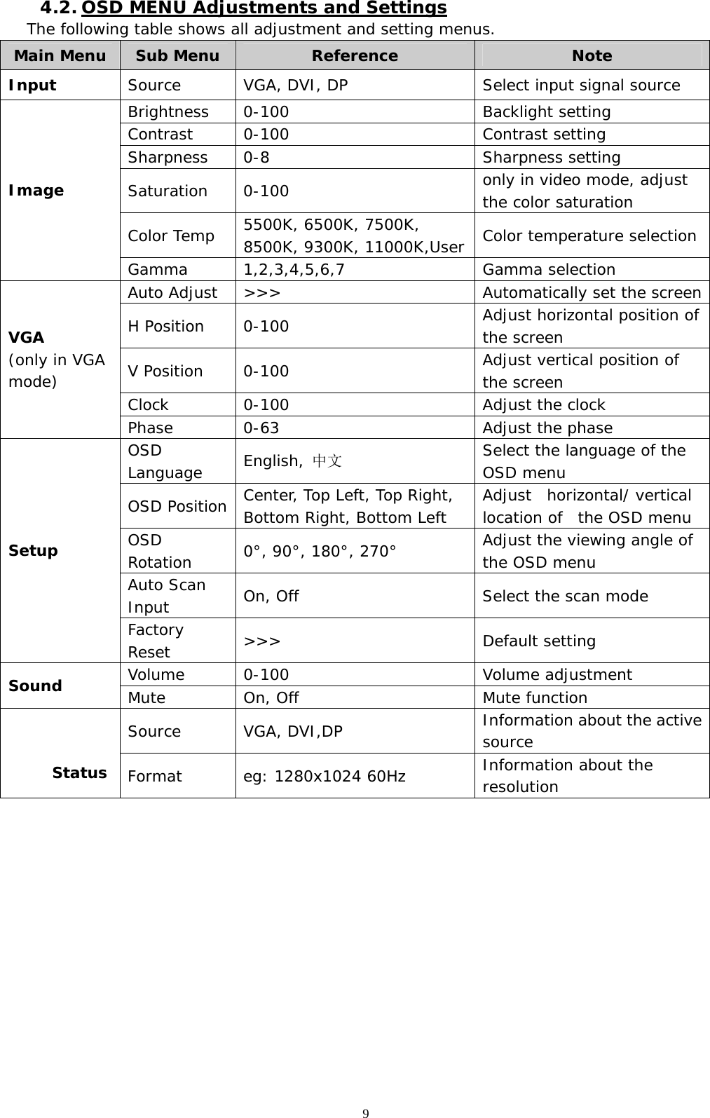
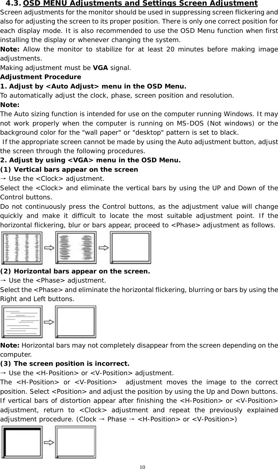
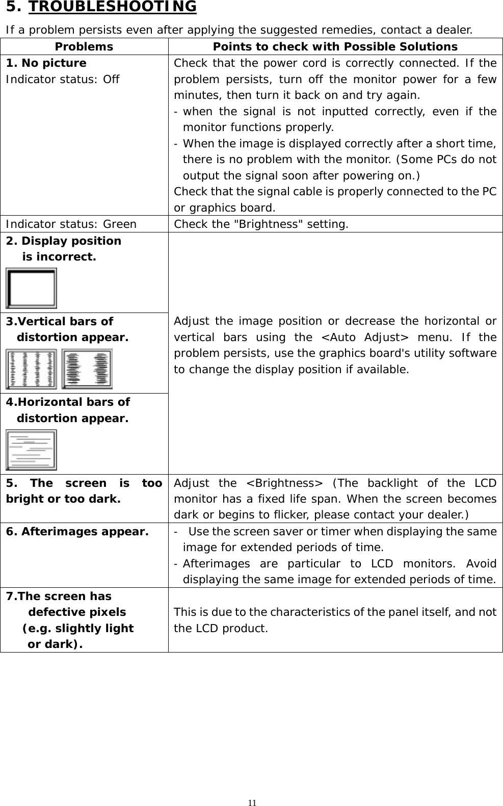
User Manual
Discussion / Help
Navigation