Beacon Display Technology C22WTC22WPC22W LCD Monitor User Manual
Shenzhen Beacon Display Technology Co., Ltd. LCD Monitor
User Manual
User Manual
21.5’’ Color LCD
Model: C22W***
REV: A0
0622282705
2
TABLE OF CONTENTS
1. SAFETY SYMBOLS & PRECAUTIONS .............................................................................. 3
1.1. SAFETY SYMBOLS......................................................................................................... 3
1.2. PRECAUTIONS................................................................................................................ 3
2. INTRODUCTION......................................................................................................................... 6
2.1. Features............................................................................................................................. 6
2.2. Package Contents......................................................................................................... 6
3. CABLE CONNECTION............................................................................................................... 7
3.1. Before Connecting ....................................................................................................... 7
3.2. Connecting the Cables............................................................................................... 7
4. ADJUSTMENT .............................................................................................................................. 8
4.1. How to Use OSD Menu............................................................................................... 8
4.2. OSD MENU Adjustments and Settings ............................................................. 9
4.3. OSD MENU Adjustments and Settings Screen Adjustment ............... 10
5. TROUBLESHOOTING..............................................................................................................11
6. CLEANING................................................................................................................................... 12
7. SPECIFICATION ...................................................................................................................... 13
7.1. Specification.................................................................................................................. 13
7.2. Display Port 20pin Connector............................................................................. 13
7.3. DVI(Digital Visual Interface) Connector...................................................... 14
7.4. D-Sub 15pin Connector........................................................................................... 14
7.5. Preset Timing ............................................................................................................... 15
8. Dimensions ................................................................................................................................ 16
9. Quick Installation Guide.................................................................................................... 17
10. Vendor .......................................................................................................................................... 18
3
1. SAFETY SYMBOLS & PRECAUTIONS
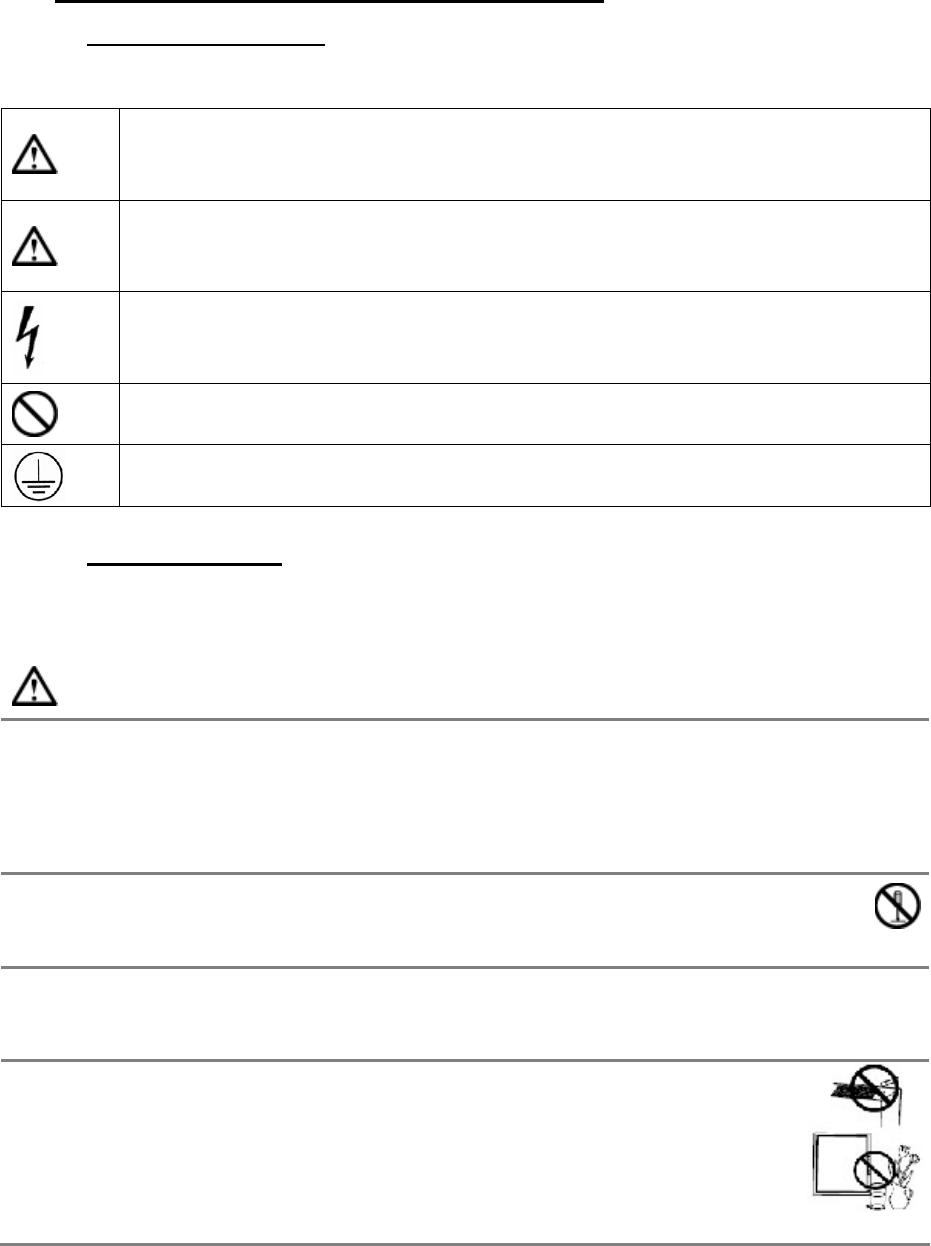
1.1. SAFETY SYMBOLS
This manual uses the safety symbols below. They denote critical information. Please
read them carefully.
WARNING
Failure to abide by the information in a WARNING may result in serious
injury and can be life threatening.
CAUTION
Failure to abide by the information in a CAUTION may result in moderate
injury and/or property or product damage.
Alert electrical hazard.
Indicates a prohibited action.
Indicates to ground for safety.
1.2. PRECAUTIONS
To ensure personal safety and proper maintenance, please read this section and the
caution statements on the unit
WARNING
If the unit begins to emit smoke, smells like something is burning, or makes
strange noises, disconnect all power connections immediately and contact
your dealer for advice.
Attempting to use a malfunctioning unit may result in fire, electric shock, or equipment
damage.
Do not open the cabinet or modify the unit.
Opening the cabinet or modifying the unit may result in fire, electric shock, or
burn.
Refer all servicing to qualified service personnel.
Do not attempt to service this product yourself as opening or removing covers may
result in fire, electric shock, or equipment damage.
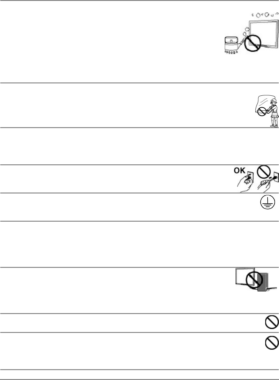
Keep small objects or liquids away from the unit.
Small objects accidentally falling through the ventilation slots into the
cabinet or spillage into the cabinet may result in fire, electric shock, or
equipment damage. If an object or liquid falls/spills into the cabinet,
unplug the unit immediately. Have the unit checked by a qualified service
engineer before using it again.
4
Set the unit in an appropriate location.
Not doing so may result in fire, electric shock, or equipment damage.
- Do not place outdoors.
- Do not place in the transportation system (ship, aircraft, trains,
automobiles, etc.
- Do not place in a dusty or humid environment.
- Do not place in a location where the steam comes directly on the screen.
- Do not place near heat generating devices or a humidifier.
- Do not place in an inflammable gas environment.
To avoid danger of suffocation, keep the plastic packing bags away from
babies and children.
Use the enclosed power cord and connect to the standard power outlet of your
country.
Be sure to remain within the rated voltage of the power cord. Not doing so may result
in fire or electric shock.
To disconnect the power cord, grasp the plug firmly and pull.
Tugging on the cord may damage and result in fire or electric shock.
The equipment must be connected to a grounded main outlet.
Not doing so may result in fire or electric shock.
Use the correct voltage.
- The unit is designed for use with a specific voltage only. Connection to another
voltage than specified in this User’s Manual may cause fire, electric shock, or
equipment damage.
- Do not overload your power circuit, as this may result in fire or electric shock.
Handle the power cord with care.
- The unit is designed for use with a specific voltage only. Connection to
another voltage than specified in this User’s Manual may cause fire,
electric shock, or equipment damage.
- Do not overload your power circuit, as this may result in fire or electric shock.
Never touch the plug and power cord if it begins to thunder.
Touching them may result in electric shock.
Do not touch a damaged LCD panel directly with bare hands.
The liquid crystal that may leak from the panel is poisonous if it enters the eyes or
mouth. If any part of the skin or body comes in direct contact with the panel, please
wash thoroughly. If some physical symptoms result, please consult your doctor.
Follow local regulation or laws for safe disposal.
5
CAUTION
Handle with care when carrying the unit.
Disconnect the power cord and signal cables and remove the optional unit. Moving the
unit with the cord or the option attached is dangerous. It may result in injury.
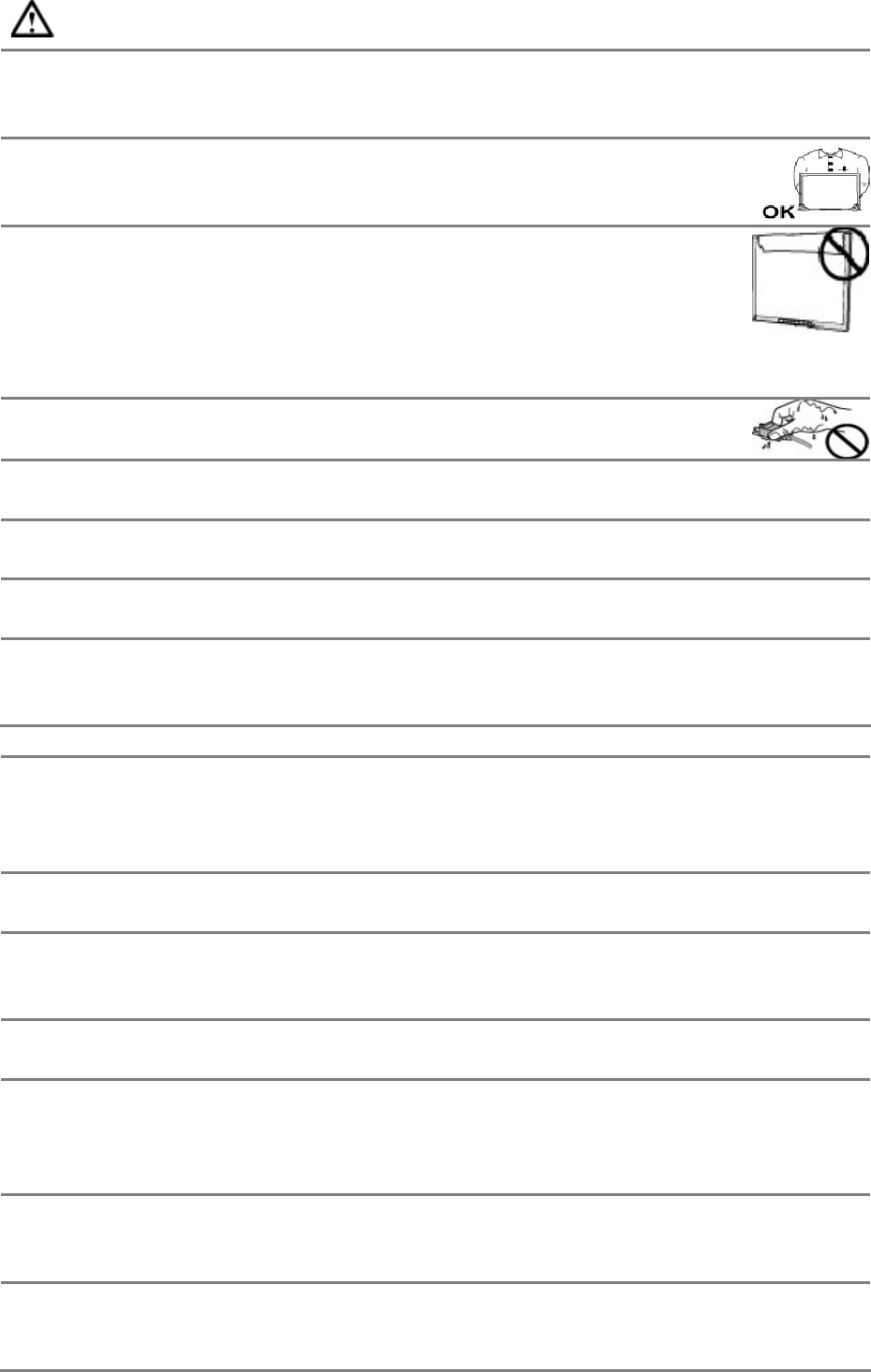
When handling the unit, grip the bottom of the unit firmly with both
hands ensuring the panel faces outward before lifting.
Dropping the unit may result in injury or equipment damage.
Do not block the ventilation slots on the cabinet.
- Do not place any objects on the ventilation slots.
- Do not install the unit in a closed space.
- Do not use the unit laid down or upside down.
- Blocking the ventilation slots prevents proper airflow and may result in fire, electric
shock, or equipment damage.
Do not touch the plug with wet hands.
Doing so may result in electric shock.
Use an easily accessible power outlet.
This will ensure that you can disconnect the power quickly in case of a problem.
Periodically clean the area around the plug.
Dust, water, or oil on the plug may result in fire.
Unplug the unit before cleaning it.
Cleaning the unit while it is plugged into a power outlet may result in electric shock.
If you plan to leave the unit unused for an extended period, disconnect the
power cord from the wall socket after turning off the power switch for the
safety and the power conservation.
LCD PANEL
When the monitor is cold and brought into a room or the room temperature goes up
quickly, dew condensation may occur inside and outside the monitor. In that case, do
not turn the monitor on and wait until dew condensation disappears, otherwise it may
cause some damages to it.
In order to suppress the luminosity change by long-term use and to maintain the stable
luminosity, please use the monitor with the lower brightness.
The screen may have defective pixels. These pixels may appear as slightly light or dark
area on the screen. This is due to the characteristics of the panel itself, and not the
product.
The backlight of the LCD panel has a fixed life span. When the screen becomes dark or
begins to flicker, please contact your dealer.
Do not press on the panel or edge of the frame strongly, as this may result in damage
to the screen. There will be prints left on the screen if the pressed image is dark or
black. If pressure is repeatedly applied to the screen, it may deteriorate or damage
your LCD panel. Leave the screen white to decrease the prints.
Do not scratch or press on the panel with any sharp objects, such as a pencil or pen as
this may result in damage to the panel. Do not attempt to brush with tissues as this
may scratch the LCD panel.
When the screen image is changed after displaying the same image for extended
periods of time, an afterimage may appear. Use the screen saver or timer to avoid
displaying the same image for extended periods of time.

6
2. INTRODUCTION
Thank you very much for choosing this monitor.
2.1. Features
- VGA analog input
- DVI digital input compliant
- Display Port 1.1a compliant
- Resolutions up to 1920x1080.
- Power management system conforms to VESA DPMS standard.
- Supports DDC1/2B for Plug & Play compatibility.
- Advanced On Screen Display (OSD) control for picture quality adjustment
2.2. Package Contents
Please contact your local dealer for assistance if any of the listed items are missing or
damaged.
- LCD Monitor
- D-sub Cable
- DVI Cable
- Display Port Cable
- Power Cable
- DC Adapter
- User Manual
Note: Please retain the packing materials for future transference.
7
3. CABLE CONNECTION
3.1. Before Connecting
Before connecting your monitor to the computer, change the display screen settings
(Resolution and frequency) in accordance with the charts below.
Note:
- The lower display modes like 640x 480, automatically enlarge to the maximum
display mode (1920 x 1080), and some lines of the characters may become fuzzy.
- When your computer and display support VESA DDC, the suitable resolution and the
refresh rate are set by just plugging your display into the computer without any
manual settings.
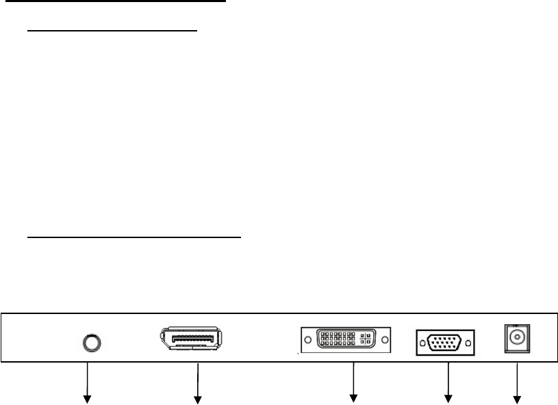
3.2. Connecting the Cables
Note: Be sure that the power switches of both the computer and the monitor are OFF.
AUDIOIN DISPLAYPORT DVI D-SUB DC IN
Audio cable Connection:
Plug the audio cable to the audio port in the rear of the PC system, and plug the other
end to the monitor;
Note: AUDIO IN port is valid for DVI and D-SUB only.
Display Port cable connection:
Plug the Display Port signal cable to the Display Port connector in the rear of the PC
system or other signal source, and plug the other end to the monitor.
DVI cable connection:
Plug the DVI signal cable to the DVI connector in the rear of the PC system, and plug the
other end to the monitor. Secure cable connectors with screws.
VGA cable connection:
Plug 15-pin VGA signal cable to the VGA connector in the rear of the PC system, and
plug the other end to the monitor. Secure cable connectors with screws.
Power cable connection:
1. Connect the adapter power cord to the DC input on the rear of the monitor.
2. Plug the power cord into the DC adapter, and plug the other end of the cord into a
power outlet

8
4. ADJUSTMENT
This monitor will not likely require adjustment. Variations in video output and
application may require adjustments to the monitor to optimize the quality of the
display.
For best performance, the monitor should be operating in native resolution 1920 x 1080.
Use the Display control panel in Windows to choose 1920 x 1080 resolution. Operating
in other resolutions will degrade video performance.
All control adjustments are automatically memorized.
4.1. How to Use OSD Menu
(1) Auto (Auto adjustment or exit OSD menu)
(2) ▲(Up or Increase value)
(3) ▼ (Down or Decrease value)
(4) Menu (Activate OSD menu)
(5) Power (Power on/off)
(6) Power indicator LED
Power indicator LED
1. Entering the OSD Menu
Press the MENU Button once to display the OSD Menu.
2. Making Adjustments and Settings
a. Select the desired sub menu icon using the Control buttons and press the MENU
button. The sub menu appears.
b. Use the Control buttons to select the desired setting icon and press the MENU button.
The setting menu appears.
c. Use the Control buttons to make all required adjustments and press the MENU button
to save the settings.
3. Exiting the OSD MENU
- To exit the OSD menu, Press <Exit> button.
Green Operating
Orange Closed
Off Power Off
9
4.2. OSD MENU Adjustments and Settings
The following table shows all adjustment and setting menus.
Main Menu Sub Menu Reference Note
Input Source VGA, DVI, DP Select input signal source
Brightness 0-100 Backlight setting
Contrast 0-100 Contrast setting
Sharpness 0-8 Sharpness setting
Saturation 0-100 only in video mode, adjust
the color saturation
Color Temp 5500K, 6500K, 7500K,
8500K, 9300K, 11000K,User
Color temperature selection
Image
Gamma 1,2,3,4,5,6,7 Gamma selection
Auto Adjust >>> Automatically set the screen
H Position 0-100 Ad
j
ust horizontal position of
the screen
V Position 0-100 Adjust vertical position of
the screen
Clock 0-100 Adjust the clock
VGA
(only in VGA
mode)
Phase 0-63 Adjust the phase
OSD
Language English, 中文 Select the language of the
OSD menu
OSD Position Center, Top Left, Top Right,
Bottom Right, Bottom Left Adjust horizontal/ vertical
location of the OSD menu
OSD
Rotation 0°, 90°, 180°, 270° Adjust the viewing angle of
the OSD menu
Auto Scan
Input On, Off Select the scan mode
Setup
Factory
Reset >>> Default setting
Volume 0-100 Volume adjustment
Sound Mute On, Off Mute function
Source VGA, DVI,DP Information about the active
source
Status Format eg: 1280x1024 60Hz Information about the
resolution
10
4.3. OSD MENU Adjustments and Settings Screen Adjustment
Screen adjustments for the monitor should be used in suppressing screen flickering and
also for adjusting the screen to its proper position. There is only one correct position for
each display mode. It is also recommended to use the OSD Menu function when first
installing the display or whenever changing the system.
Note: Allow the monitor to stabilize for at least 20 minutes before making image
adjustments.
Making adjustment must be VGA signal.
Adjustment Procedure
1. Adjust by <Auto Adjust> menu in the OSD Menu.
To automatically adjust the clock, phase, screen position and resolution.
Note:
The Auto sizing function is intended for use on the computer running Windows. It may
not work properly when the computer is running on MS-DOS (Not windows) or the
background color for the "wall paper" or "desktop" pattern is set to black.
If the appropriate screen cannot be made by using the Auto adjustment button, adjust
the screen through the following procedures.
2. Adjust by using <VGA> menu in the OSD Menu.
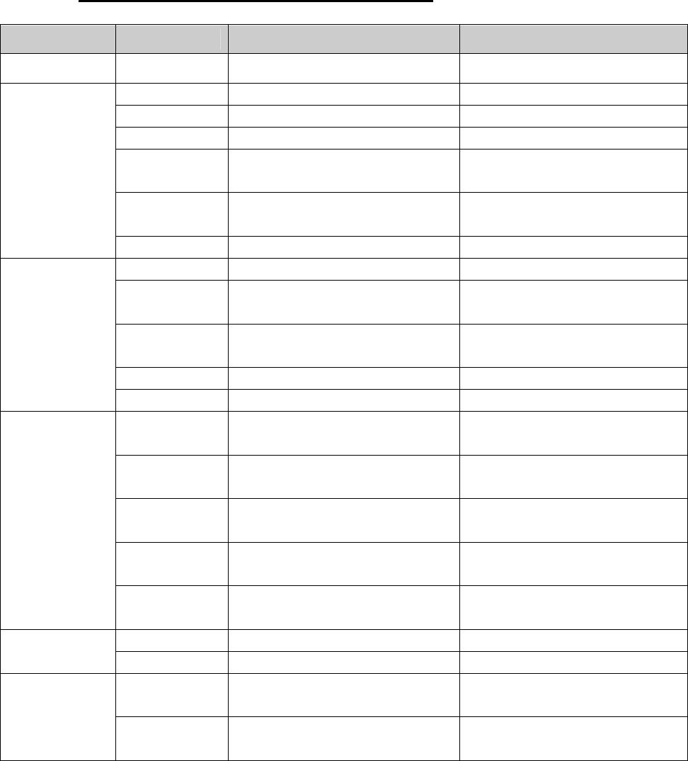
(1) Vertical bars appear on the screen
Use the <Clock> adjustment.→
Select the <Clock> and eliminate the vertical bars by using the UP and Down of the
Control buttons.
Do not continuously press the Control buttons, as the adjustment value will change
quickly and make it difficult to locate the most suitable adjustment point. If the
horizontal flickering, blur or bars appear, proceed to <Phase> adjustment as follows.
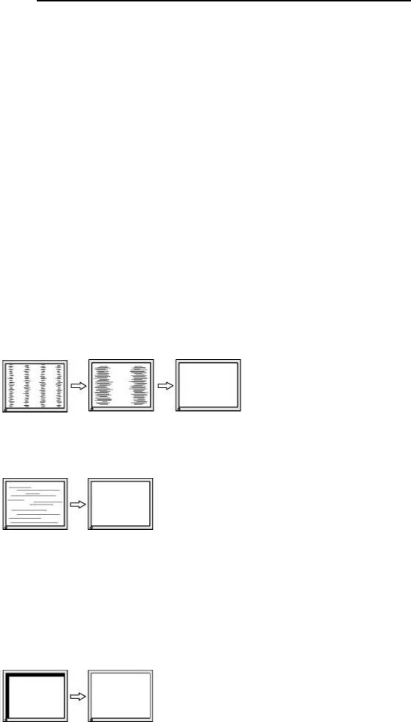
(2) Horizontal bars appear on the screen.
Use the <Phase> adjustment.→
Select the <Phase> and eliminate the horizontal flickering, blurring or bars by using the
Right and Left buttons.
Note: Horizontal bars may not completely disappear from the screen depending on the
computer.
(3) The screen position is incorrect.
Use the <→H-Position> or <V-Position> adjustment.
The <H-Position> or <V-Position> adjustment moves the image to the correct
position. Select <Position> and adjust the position by using the Up and Down buttons.
If vertical bars of distortion appear after finishing the <H-Position> or <V-Position>
adjustment, return to <Clock> adjustment and repeat the previously explained
adjustment procedure. (Clock Phase <→→H-Position> or <V-Position>)
11
5. TROUBLESHOOTING
If a problem persists even after applying the suggested remedies, contact a dealer.
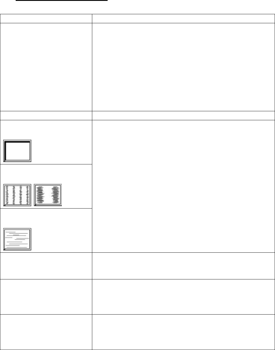
Problems Points to check with Possible Solutions
1. No picture
Indicator status: Off Check that the power cord is correctly connected. If the
problem persists, turn off the monitor power for a few
minutes, then turn it back on and try again.
- when the signal is not inputted correctly, even if the
monitor functions properly.
- When the image is displayed correctly after a short time,
there is no problem with the monitor. (Some PCs do not
output the signal soon after powering on.)
Check that the signal cable is properly connected to the PC
or graphics board.
Indicator status: Green Check the "Brightness" setting.
2. Display position
is incorrect.
3.Vertical bars of
distortion appear.
4.Horizontal bars of
distortion appear.
Adjust the image position or decrease the horizontal or
vertical bars using the <Auto Adjust> menu. If the
problem persists, use the graphics board's utility software
to change the display position if available.
5. The screen is too
bright or too dark. Adjust the <Brightness> (The backlight of the LCD
monitor has a fixed life span. When the screen becomes
dark or begins to flicker, please contact your dealer.)
6. Afterimages appear. - Use the screen saver or timer when displaying the same
image for extended periods of time.
- Afterimages are particular to LCD monitors. Avoid
displaying the same image for extended periods of time.
7.The screen has
defective pixels
(e.g. slightly light
or dark).
This is due to the characteristics of the panel itself, and not
the LCD product.

12
6. CLEANING
Periodic cleaning is recommended to keep the monitor looking new and to prolong its
operation lifetime.
Note: Never use thinner, benzene, alcohol (ethanol, methanol, or isopropyl alcohol),
abrasive cleaners, or other strong solvents, as these may cause damage to the cabinet
or LCD panel.
Cabinet
To remove stains, wipe the cabinet with a soft, lightly moistened cloth using a mild
detergent. Do not spray wax or cleaner directly into the cabinet. (For details, refer to
the manual of the PC.)
LCD Panel
The LCD surface can be cleaned with a soft cloth, such as cotton or lens paper.
If necessary, stubborn stains can be removed by moistening part of a cloth with water
to enhance its cleaning power.
13
7. SPECIFICATION
7.1. Specification
Display
characteristics
Size: 21.5″ active display
Supported color : 16.7M colors
Native resolution: 1920 x1080
Pixel pitch: 0.248 x 0.248 mm
Viewing angle: R/L 170°, U/D 160° @ contrast ratio = 10
Brightness: 250cd/㎡Typ
Contrast ratio: 3000:1Typ.
Response time: 25 ms Typ.
Vertical frequency: 50-76 Hz
Horizontal frequency: 31-80 kHz
External
connections
Digital signal: Display Port, DVI-D
Analog Video Input: 15 pin D-sub
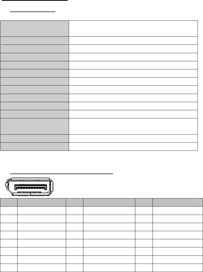
7.2. Display Port 20pin Connector
Pin signal Pin
signal Pin
signal
1 ML_Lane 3(n) 9 ML_Lane 1(p) 17 AUX_CH(n)
2 GND 10 ML_Lane 0(n) 18 HOT-PLUG
3 ML_Lane 3(p) 11 GND 19 RTN
4 ML_Lane 2(n) 12 ML_Lane 0(p) 20 DP_PWR
5 GND 13 GND
6 ML_Lane 2(p) 14 GND
7 ML_Lane 1(n) 15 AUX_CH(p)
8 GND 16 GND
14
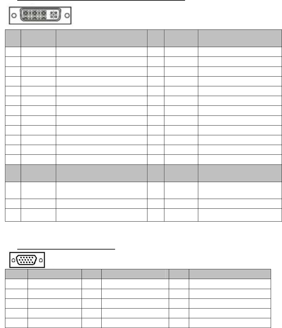
7.3. DVI(Digital Visual Interface) Connector
Pin
Signal Description Pin
Signal Description
1 TX2- Channel 2 Data - 13
TX3+ NC
2 TX2+ Channel 2 Data + 14
+5V +5 V from input
3 SHLD2/4
Channels 2 and 4 Shield 15
5V_GND
Ground for +5 V
4 TX4- NC 16
HPD Hot Plug Detection
5 TX4+ NC 17
TX0- Channel 0 Data -
6 SCL DDC Clock 18
TX0+ Channel 0 Data +
7 SDA DDC Data (bidirectional) 19
SHLD0/5
Channels 0 and 5 Shield
8 VSYNC NC 20
TX5- NC
9 TX1- Channel 1 Data - 21
TX5+ NC
10 TX1+ Channel 1 Data + 22
SCL_GND
DDC Clock Ground
11 SHLD1/3
Channels 1 and 3 Shield 23
TXC+ Clock +
12 TX3- NC 24
TXC- Clock -
Pin
Code Analogue Function Pin
Code Analogue Function
C1 R NC C4
HSYNC NC
C2 G NC C5
ANL_GND
Ground
C3 B NC
Note: This connector only supports the DVI-D signal.
7.4. D-Sub 15pin Connector
Pin Signal Pin
Signal Pin
Signal
1 Red video 6 Red ground 11 Ground Shorted
2 Green video 7 Green ground 12 Data (SDA)
3 Blue video 8 Blue ground 13 H. Sync
4 Ground 9 5V 14 V. Sync
5 GND 10 Ground Shorted 15 Clock (SCL)
15
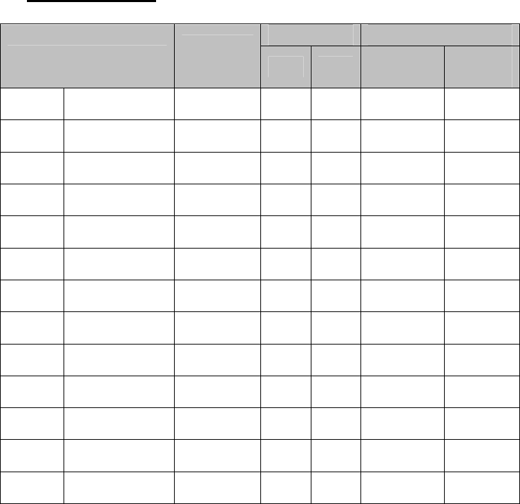
7.5. Preset Timing
polarity Frequency
Mode PixelClk
MHz H V FH
(kHz) FV
(Hz)
VGA 640 x 480 25.175 - - 31.469 59.940
VGA 720x400 28.320 + + 31.469 70.087
VESA 640x480 31.500 - - 37.500 75.000
VESA 800 x 600 40.000 + + 37.879 60.317
VESA 800 x 600 49.500 + + 46.875 75.000
VESA 1024 x 768 65.000 - - 48.363 60.004
VESA 1024 x768 75.000 - - 56.476 70.069
VESA 1024 x768 78.750 - - 60.023 75.029
VESA 1280 x 1024 108.000 + + 63.981 60.020
VESA 1280 x 1024 135.000 + + 79.976 75.025
VESA 1360 x 768 85.500 + + 47.712 60.015
VESA 1680 x 1050 146.250 + + 65.290 59.954
VEA 1920 x 1080 173.000 - + 67.158 59.963
16
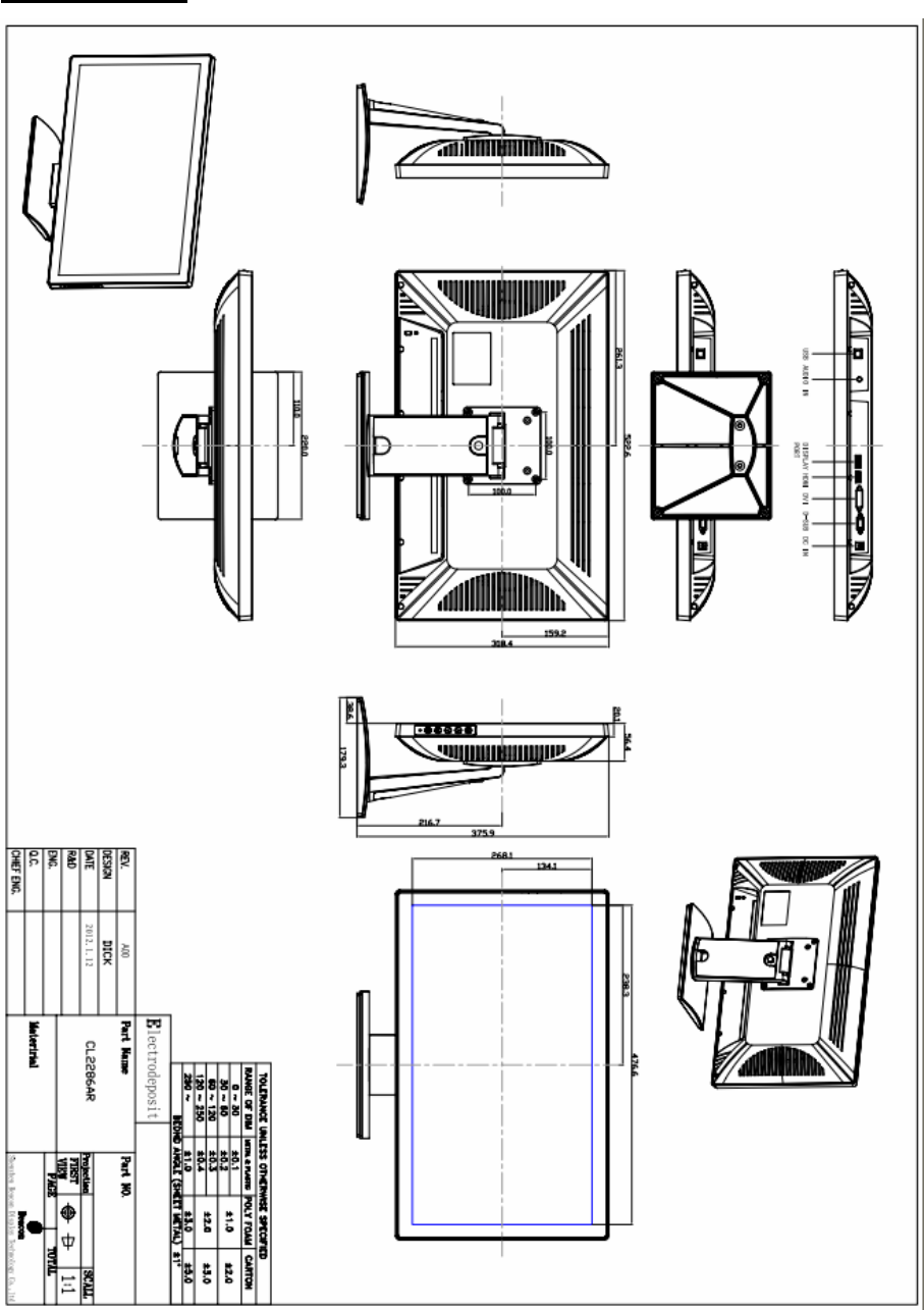
8. Dimensions
17
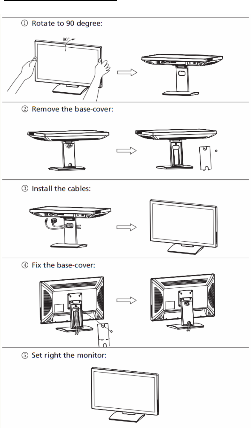
9. Quick Installation Guide

18
10. Vendor
Europe: Headquarter (North America):
FCC Warning:
z This device complies with Part 15 of the FCC Rules. Operation is subject to the
following two conditions:
z (1) this device may not cause harmful interference, and
z (2) this device must accept any interference received, including interference that may
cause undesired operation.
z Changes or modifications not expressly approved by the party responsible for compliance
could void the user's authority to operate the equipment.
z NOTE: This equipment has been tested and found to comply with the limits for a Class B
digital device, pursuant to Part 15 of the FCC Rules. These limits are designed to provide
reasonable protection against harmful interference in a residential installation. This
equipment generates, uses and can radiate radio frequency energy and, if not installed and
used in accordance with the instructions, may cause harmful interference to radio
communications. However, there is no guarantee that interference will not occur in a
particular installation. If this equipment does cause harmful interference to radio or
television reception, which can be determined by turning the equipment off and on, the
user is encouraged to try to correct the interference by one or more of the following
measures:
z -- Reorient or relocate the receiving antenna.
z -- Increase the separation between the equipment and receiver.
z -- Connect the equipment into an outlet on a circuit different from that to which the
receiver is connected.
z -- Consult the dealer or an experienced radio/TV technician for help.