Beautiful Enterprise BTBE1A Bluetooth Module User Manual
Beautiful Enterprise Co., Ltd. Bluetooth Module
UserManual.wiki
>
Beautiful Enterprise
>
BTBE1A User Manual
User Manual
Navigation menu
Upload a User Manual
Namespaces
Wiki Guide
HTML
PDF
Info
Views
User Manual
Discussion / Help
Navigation
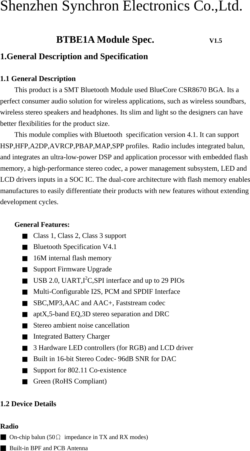
![Shenzhen Synchron Electronics Co.,Ltd. 2.Package Information 2.1 Pin-out Diagram Figure 1: BTBE1A Module Pin-out(Top View) 2.2 Terminal Functions Pin Name Pin Number Description GND 1 Ground AIO[0] 2 Analogue programmable input / output line AIO[1] 3 PCM_OUT 4 Synchronous data output Alternative function PIO[18] PCM_IN 5 Synchronous data input Alternative function PIO[17] PCM_CLK 6 Synchronous data clock Alternative function PIO[20] PCM_SYNC 7 Synchronous data sync Alternative function PIO[19]. GND 8 Ground](https://usermanual.wiki/Beautiful-Enterprise/BTBE1A/User-Guide-3010087-Page-5.png)
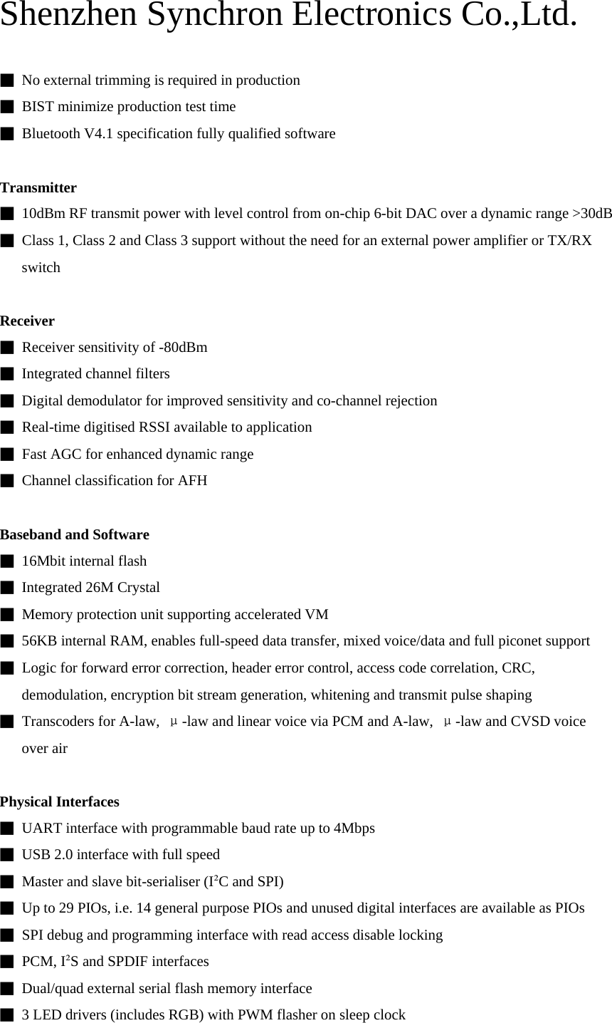
![Shenzhen Synchron Electronics Co.,Ltd. SPI_MOSI 9 SPI data input SPI_CLK 10 SPI clock SPI_MISO 11 SPI data output SPI_CS# 12 Chip select for SPI, active low UART_RX 13 UART data input UART_TX 14 UART data output UART_RTS 15 UART request to send, active low Alternative function PIO[16] UART_CTS 16 UART clear to send, active low GND 17 Ground RST# 18 Reset if low. Input debounced so must be low for >5ms to cause a reset PIO[0] 19 Programmable input / output line GND 20 Ground LED[0]_GREEN 21 LED driver LED[2]_RED 22 LED[1]_BLUE 23 PIO[1] 24 Programmable input / output line PIO[2] 25 PIO[3] 26 PIO[15] 27 PIO[4] 28 PIO[6] 29 PIO[7] 30 PIO[14] 31 PIO[11] 32 GND 33 Ground USB_P 34 USB data plus with selectable internal 1.5kΩpull-up resistor USB_N 35 USB data minus GND 36 Ground VBAT_SENSE 37 Battery charger sense input GND 38 Ground VBAT 39 Battery positive terminal CHG_EXT 40 External battery charger control VBUS 41 Battery charger input GND 42 Ground](https://usermanual.wiki/Beautiful-Enterprise/BTBE1A/User-Guide-3010087-Page-6.png)