Beautiful Enterprise BTBE1A Bluetooth Module User Manual
Beautiful Enterprise Co., Ltd. Bluetooth Module
User Manual
Shenzhen Synchron Electronics Co.,Ltd.
BTBE1A Module Spec. V1.5
1.General Description and Specification
1.1 General Description
This product is a SMT Bluetooth Module used BlueCore CSR8670 BGA. Its a
perfect consumer audio solution for wireless applications, such as wireless soundbars,
wireless stereo speakers and headphones. Its slim and light so the designers can have
better flexibilities for the product size.
This module complies with Bluetoothٛspecification version 4.1. It can support
HSP,HFP,A2DP,AVRCP,PBAP,MAP,SPP profiles. Radio includes integrated balun,
and integrates an ultra-low-power DSP and application processor with embedded flash
memory, a high-performance stereo codec, a power management subsystem, LED and
LCD drivers inputs in a SOC IC. The dual-core architecture with flash memory enables
manufactures to easily differentiate their products with new features without extending
development cycles.
General Features:
■ Class 1, Class 2, Class 3 support
■ Bluetooth Specification V4.1
■ 16M internal flash memory
■ Support Firmware Upgrade
■ USB 2.0, UART,I2C,SPI interface and up to 29 PIOs
■ Multi-Configurable I2S, PCM and SPDIF Interface
■ SBC,MP3,AAC and AAC+, Faststream codec
■ aptX,5-band EQ,3D stereo separation and DRC
■ Stereo ambient noise cancellation
■ Integrated Battery Charger
■ 3 Hardware LED controllers (for RGB) and LCD driver
■ Built in 16-bit Stereo Codec- 96dB SNR for DAC
■ Support for 802.11 Co-existence
■ Green (RoHS Compliant)
1.2 Device Details
Radio
■ On-chip balun (50Ω impedance in TX and RX modes)
■ Built-in BPF and PCB Antenna
Shenzhen Synchron Electronics Co.,Ltd.
■ No external trimming is required in production
■ BIST minimize production test time
■ Bluetooth V4.1 specification fully qualified software
Transmitter
■ 10dBm RF transmit power with level control from on-chip 6-bit DAC over a dynamic range >30dB
■ Class 1, Class 2 and Class 3 support without the need for an external power amplifier or TX/RX
switch
Receiver
■ Receiver sensitivity of -80dBm
■ Integrated channel filters
■ Digital demodulator for improved sensitivity and co-channel rejection
■ Real-time digitised RSSI available to application
■ Fast AGC for enhanced dynamic range
■ Channel classification for AFH
Baseband and Software
■ 16Mbit internal flash
■ Integrated 26M Crystal
■ Memory protection unit supporting accelerated VM
■ 56KB internal RAM, enables full-speed data transfer, mixed voice/data and full piconet support
■ Logic for forward error correction, header error control, access code correlation, CRC,
demodulation, encryption bit stream generation, whitening and transmit pulse shaping
■ Transcoders for A-law, μ-law and linear voice via PCM and A-law, μ-law and CVSD voice
over air
Physical Interfaces
■ UART interface with programmable baud rate up to 4Mbps
■ USB 2.0 interface with full speed
■ Master and slave bit-serialiser (I²C and SPI)
■ Up to 29 PIOs, i.e. 14 general purpose PIOs and unused digital interfaces are available as PIOs
■ SPI debug and programming interface with read access disable locking
■ PCM, I²S and SPDIF interfaces
■ Dual/quad external serial flash memory interface
■ 3 LED drivers (includes RGB) with PWM flasher on sleep clock

Shenzhen Synchron Electronics Co.,Ltd.
Kalimba DSP
■ Enhanced Kalimba DSP coprocessor, 80MIPS, 24‑bit fixed point core
■ 2 single-cycle MACs; 24 x 24-bit multiply and 56-bit accumulator
■ 32-bit instruction word, dual 24-bit data memory
■ 32-bit instruction word, dual 24-bit data memory
■ 12K x 32-bit program RAM including 1K instruction cache for executing out of internal flash
■ 32K x 24-bit + 32K x 24-bit 2-bank data RAM
Audio
■ Audio codec with 2 high-quality dedicated ADCs
■ 2 microphone bias generators and up to 2 analogue microphone inputs
■ Up to 6 digital microphone (MEMS) inputs
■ G.722 compatible, includes improved digital FIR filter path for stop-band attenuation required for
G.722 compliance
■ Enhanced side-tone gain control
■ Supported sample rates of 8, 11.025, 16, 22.05, 32, 44.1,48 and 96kHz (DAC only)
Auxiliary Features
■ On-chip regulators:
3.3V USB pad supply linear regulator, Low-voltage linear regulator for internal digital supply with
0.80V to 1.25V output, Low-voltage linear regulator for internal analogue supply with 1.35V
output
■ On-chip high-efficiency switch-mode regulator:
1.8V and1.35V outputs from battery supply
■ Power-on-reset cell detects low supply voltage
■ Power management includes digital shutdown and wake-up commands with an integrated
low-power oscillator for ultra-low power Park/Sniff/Hold mode
■ Built-in Lithium ion / Lithium polymer battery charger with optional external mode
■ Crystal oscillator with built-in digital trimming
■ Clock request output to control external clock
■ Auxiliary ADC and DAC available to applications
1.3 Specification
Brand name
Model No. BTBE1A
Chipset CSR8670
Specification Version Bluetooth V4.1

Shenzhen Synchron Electronics Co.,Ltd.
Power Class Class2
Frequency Band 2.402~2.480GHz
Max. TX Power -6~+4dBm
RX Sensitivity -80dBm@0.1%BER
Hopping 1600hops/sec, 1MHz channel space
Channel No. 79
Data Rate
1 Mbps for Basic Rate using GFSK
2 Mbps for Enhanced Data Rate using
π/4-DQPSK
3 Mbps for Enhanced Data Rate using
8DPSK
Modulation Type GFSK, π/4-DQPSK,8DPSK
Crystal 26MHz
Distance >10m(Class2 without obstacle)
Flash Size 16M
Operation Temperature -10 ~ +45 ℃
Dimension 27.5mm(L)x 20 mm(W) x 0.8mm(H)
Shenzhen Synchron Electronics Co.,Ltd.
2.Package Information
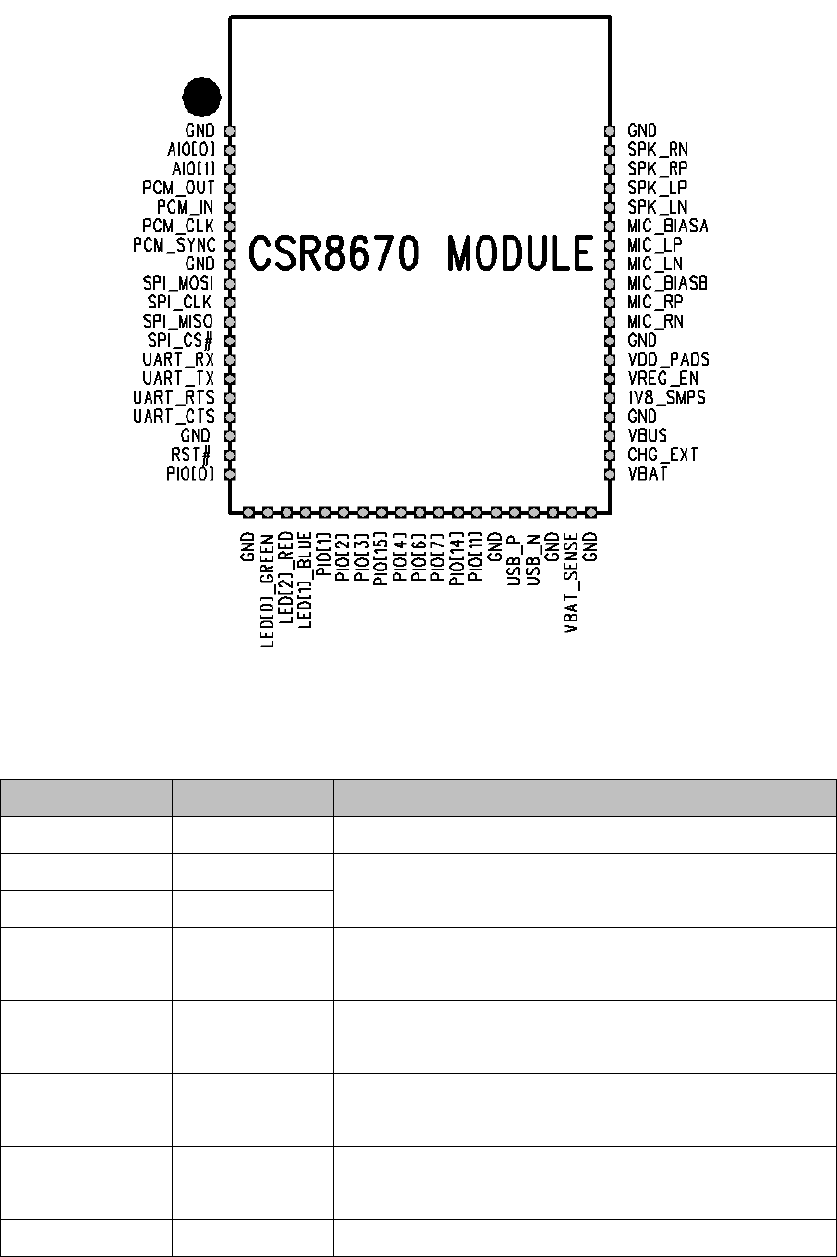
2.1 Pin-out Diagram
Figure 1: BTBE1A Module Pin-out(Top View)
2.2 Terminal Functions
Pin Name Pin Number Description
GND 1 Ground
AIO[0] 2
Analogue programmable input / output line
AIO[1] 3
PCM_OUT 4 Synchronous data output
Alternative function PIO[18]
PCM_IN 5 Synchronous data input
Alternative function PIO[17]
PCM_CLK 6 Synchronous data clock
Alternative function PIO[20]
PCM_SYNC 7 Synchronous data sync
Alternative function PIO[19].
GND 8 Ground

Shenzhen Synchron Electronics Co.,Ltd.
SPI_MOSI 9 SPI data input
SPI_CLK 10 SPI clock
SPI_MISO 11 SPI data output
SPI_CS# 12 Chip select for SPI, active low
UART_RX 13 UART data input
UART_TX 14 UART data output
UART_RTS 15 UART request to send, active low
Alternative function PIO[16]
UART_CTS 16 UART clear to send, active low
GND 17 Ground
RST# 18
Reset if low. Input debounced so must be low
for >5ms to cause a reset
PIO[0] 19 Programmable input / output line
GND 20 Ground
LED[0]_GREEN 21
LED driver LED[2]_RED 22
LED[1]_BLUE 23
PIO[1] 24
Programmable input / output line
PIO[2] 25
PIO[3] 26
PIO[15] 27
PIO[4] 28
PIO[6] 29
PIO[7] 30
PIO[14] 31
PIO[11] 32
GND 33 Ground
USB_P 34 USB data plus with selectable internal 1.5kΩ
pull-up resistor
USB_N 35 USB data minus
GND 36 Ground
VBAT_SENSE 37 Battery charger sense input
GND 38 Ground
VBAT 39 Battery positive terminal
CHG_EXT 40 External battery charger control
VBUS 41 Battery charger input
GND 42 Ground
Shenzhen Synchron Electronics Co.,Ltd.
1V8_SMPS 43 1.8V output
VREG_EN 44 Regulator enable input
VDD_PADS 45 1.7V to 3.6V positive supply input
GND 46 Ground
MIC_RN 47 Microphone input negative, right
MIC_RP 48 Microphone input positive, right
MIC_BIASB 49 Microphone bias B
MIC_LN 50 Microphone input negative, left
MIC_LP 51 Microphone input positive, left
MIC_BIASA 52 Microphone bias A
SPK_LN 53 Speaker output negative, left
SPK_LP 54 Speaker output positive, left
SPK_RP 55 Speaker output positive, right
SPK_RN 56 Speaker output negative, right
GND 57 Ground
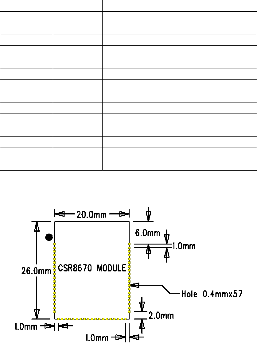
2.3 Package Dimensions
Figure 2: BTBE1A Module package Dimensions
Shenzhen Synchron Electronics Co.,Ltd.
3.Hardware Description
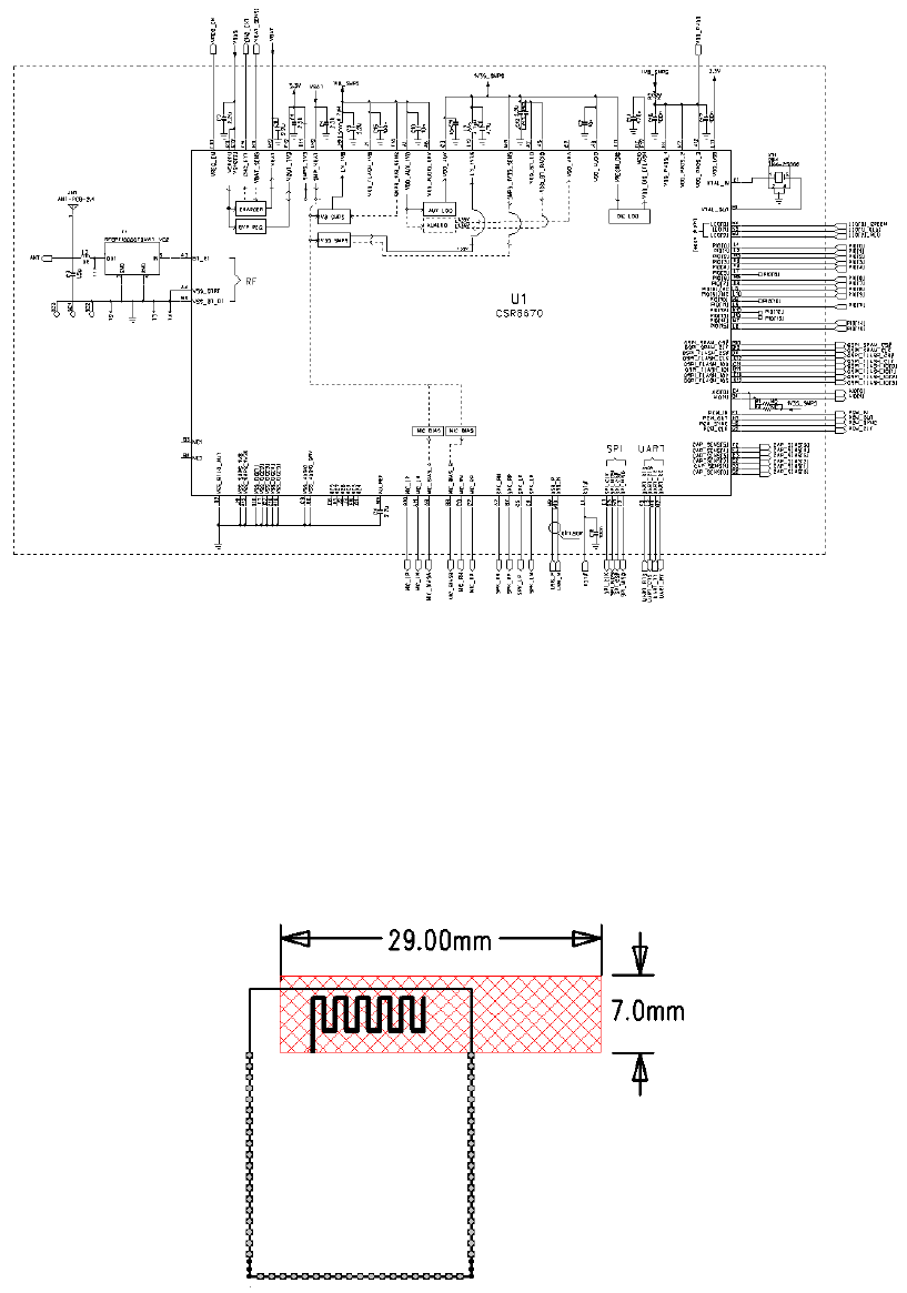
3.1 Reference Schematic
Figure 3: BTBE1A Module Reference Schematic
3.2 Mounting condition
To achieve better RF performance, the area around antenna in red color as below
is the minimum safe area which should be kept away from copper and any other metal.
And it is recommended to lay the antenna at the edge of the mother board while
mounting the Module.
Figure 4: BTBE1A Module mounting condition
Shenzhen Synchron Electronics Co.,Ltd.
3.3 Reset
This Module is reset from several sources: RST# pin, power-on reset, USB
charger attach reset, UART break character and software configured watchdog timer.
The RST# pin is an active low reset and is internally filtered using the internal
low frequency clock oscillator. Keep RST# for low period >5ms is recommended.
Shenzhen Synchron Electronics Co.,Ltd.
4. ELECTRICAL CHARACTERISTIC
4.1 Absolute Maximum Ratings
Rating Min. Max. Unit
Storage temperature -40 105 °C
Supply Voltage
VBAT -0.4 4.4 V
VBUS -0.4 5.75 V
VBAT_SENSE -0.4 5.75 V
4.2 Recommended Operating Conditions
Rating Min. Typ. Max. Unit
Operating temperature range -10 25 45 °C
Supply Voltage
VBAT 2.80 3.70 4.25 V
VBUS 4.75 5.00 5.75 V
VBAT_SENSE 0 3.70 4.25 V
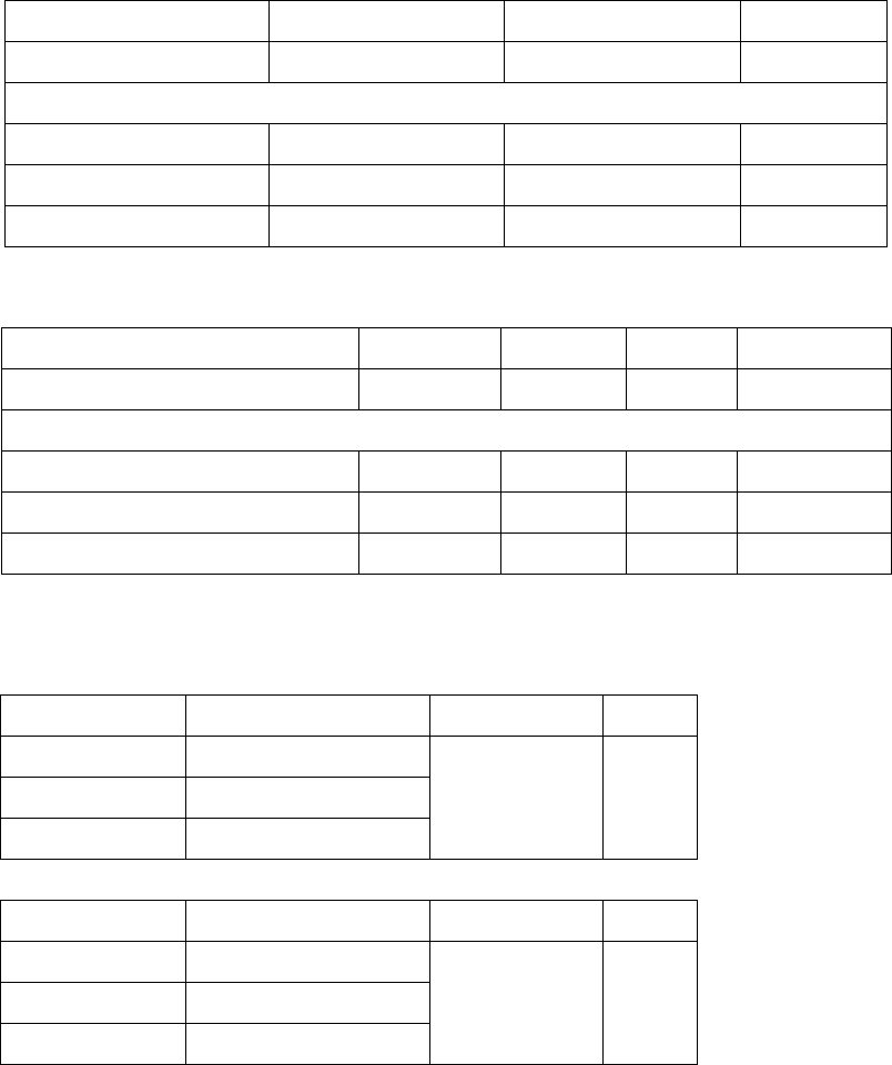
4.3 RF Characteristics (Class 2)
4.3.1 Transmitter output power
Freq. Average power Limit Unit
2402MHz -1
-6~+4 dbm
2441MHz 0
2480MHz 1
4.3.2 Receiver Sensitivity @0.1% BER
Freq. Average sensitivity Limit Unit
2402MHz -84
<=-70 dbm 2441MHz -85
2480MHz -86
Shenzhen Synchron Electronics Co.,Ltd.
5. Green Products and RoHS Compliance
Shenzhen Synchron Electronics Co.,Ltd.
6.Caution for user
FCC Statement
This equipment has been tested and found to comply with the limits for a Class B digital device,
pursuant to Part 15 of the FCC Rules. These limits are designed to provide reasonable
protection against harmful interference in a residential installation. This equipment generates,
uses and can radiate radio frequency energy and, if not installed and used in accordance with
the instructions, may cause harmful interference to radio communications. However, there is
no guarantee that interference will not occur in a particular installation. If this equipment does
cause harmful interference to radio or television reception, which can be determined by turning
the equipment off and on, the user is encouraged to try to correct the interference by one of the
following measures:
- Reorient or relocate the receiving antenna.
- Increase the separation between the equipment and receiver.
- Connect the equipment into an outlet on a circuit different from that to which the receiver is
connected.
- Consult the dealer or an experienced radio/TV technician for help.
FCC Caution:
Any changes or modifications not expressly approved by the party responsible for compliance
could void the user's authority to operate this equipment.
This device complies with Part 15 of the FCC Rules. Operation is subject to the following two
conditions:
(1) This device may not cause harmful interference, and
(2) This device must accept any interference received, including interference that may cause
undesired operation.
FCC Radiation Exposure Statement:
This equipment complies with FCC radiation exposure limits set forth for an uncontrolled
environment.
This End equipment should be installed and operated with a minimum distance of 20
centimeters between the radiator and your body.
IMPORTANT NOTE:
In the event that these conditions can not be met (for example certain laptop configurations or
co-location with another transmitter), then the FCC authorization is no longer considered valid
and the FCC ID can not be used on the final product. In these circumstances, the OEM
integrator will be responsible for re-evaluating the end product (including the transmitter) and

Shenzhen Synchron Electronics Co.,Ltd.
obtaining a separate FCC authorization.
End Product Labeling
The final end product must be labeled in a visible area with the following:
“Contains FCC ID:UZZBTBE1A”.
Manual Information to the End User
The OEM integrator has to be aware not to provide information to the end user regarding how
to install or remove this RF module in the user’s manual of the end product which integrates
this module.
Canada Statement
This device complies with Industry Canada’s licence-exempt RSSs.. Operation is subject to
the following two conditions: (1) this device may not cause interference, and (2) this device
must accept any interference, including interference that may cause undesired operation of the
device.
Le présent appareil est conforme aux CNR d'Industrie Canada applicables aux appareils radio
exempts de licence. L'exploitation est autorisée aux deux conditions suivantes : (1) l'appareil
ne doit pas produire de brouillage, et (2) l'utilisateur de l'appareil doit accepter tout brouillage
radioélectrique subi, même si le brouillage est susceptible d'en compromettre le
fonctionnement.
Caution Exposure:
This device meets the exemption from the routine evaluation limits in section 2.5 of RSS102
and users can obtain Canadian information on RF exposure and compliance.
Le dispositif répond à l'exemption des limites d'évaluation de routine dans la section 2.5 de
RSS102 et les utilisateurs peuvent obtenir des renseignements canadiens sur l'exposition aux
RF et le respect.
The final end product must be labelled in a visible area with the following:
The Industry Canada certification label of a module shall be clearly visible at all times when
installed in the host device, otherwise the host device must be labelled to display the Industry
Canada certification number of the module, preceded by the words “Contains transmitter
module”, or the word “Contains”, or similar wording expressing the same meaning, as follows:
Contains transmitter module IC: 7633A-BTBE1A
Le produit final doit être étiqueté dans une zone visible de ce qui suit:
Shenzhen Synchron Electronics Co.,Ltd.
L'étiquette d'un module de certification Industrie Canada doit être clairement
visible en tout temps lorsqu'il est installé dans le dispositif hôte, sinon le
dispositif hôte doit être étiqueté pour afficher le numéro de certification
Industrie Canada du module, précédée de la mention "Contient le module
émetteur", ou le mot “Contient” ou un libellé similaire exprimant le même sens,
comme suit:
Contient le module émetteur IC: 7633A-BTBE1A
This End equipment should be installed and operated with a minimum distance of 20
centimeters between the radiator and your body.
Cet équipement devrait être installé et actionné avec une distance minimum de 20 centimètres
entre le radiateur et votre corps.
The end user manual shall include all required regulatory information/warning as show in this
manual.
以下內容僅適用於台灣版本:
本產品符合低功率電波輻射性電機管理辦法:
第十二條 經型式認證合格之低功率射頻電機,非經許可,公司、商號或使用者均不得擅自變更
頻率、加大功率或變更原設計之特性及功能。
第十四條 低功率射頻電機之使用不得影響飛航安全及干擾合法通信;經發現有干擾現象時,應
立即停用,並改善至無干擾時方得繼續使用。
前項合法通信,指依電信法規定作業之無線電通信。低功率射頻電機須忍受合法通信或工業、科
學及醫療用電波輻射性電機設備之干擾。
本模組於取得認證后將依認規定於模本體標示審驗合格標簽,并要求平台廠商於平台上標示: