Becker Avionics AR6201 VHF-Transceiver User Manual J VPDATA 14300 Maint and Rep TITEL in op vp

Becker Flugfunkwerk GmbH VHF-Transceiver J VPDATA 14300 Maint and Rep TITEL in op vp

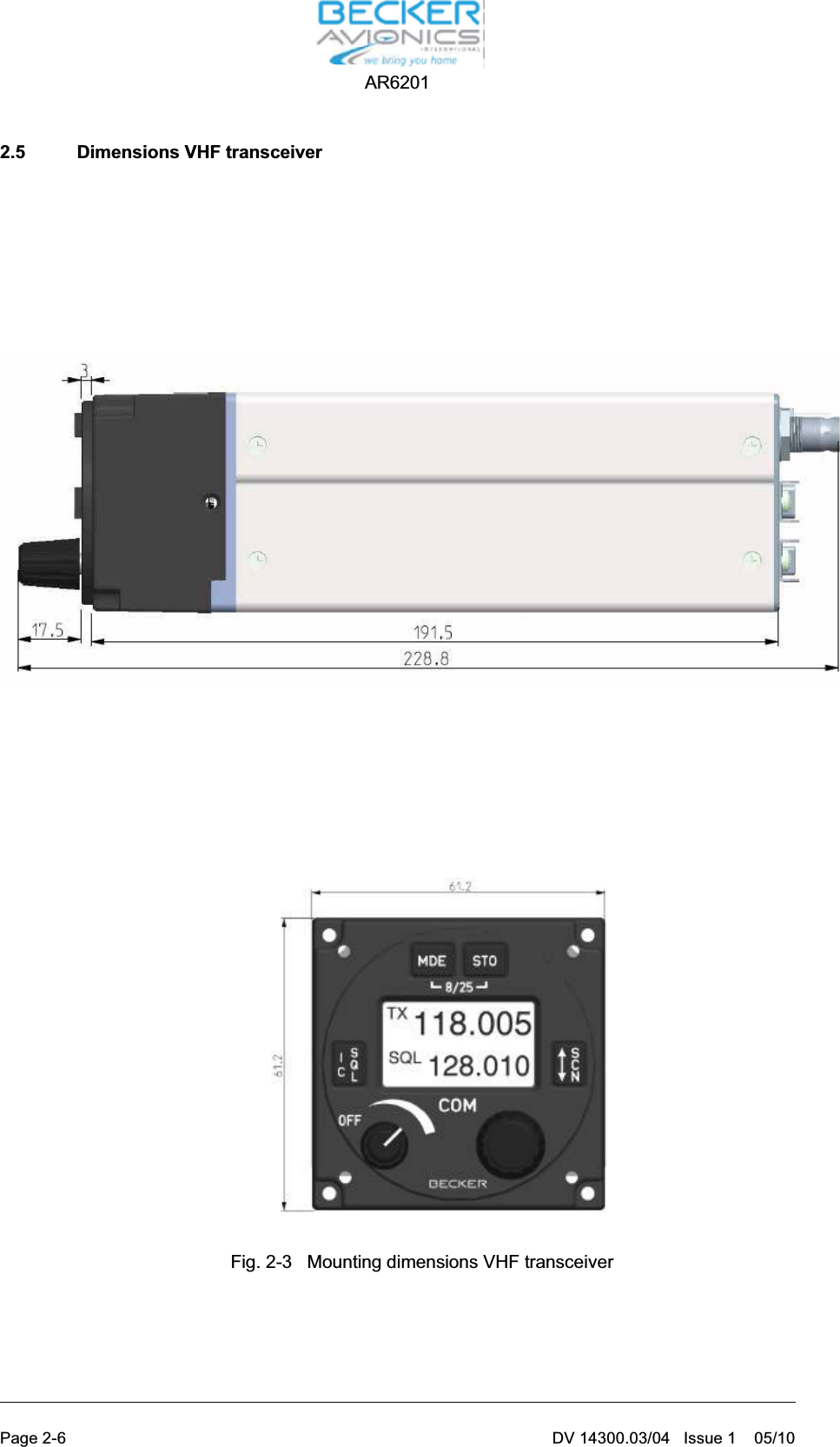
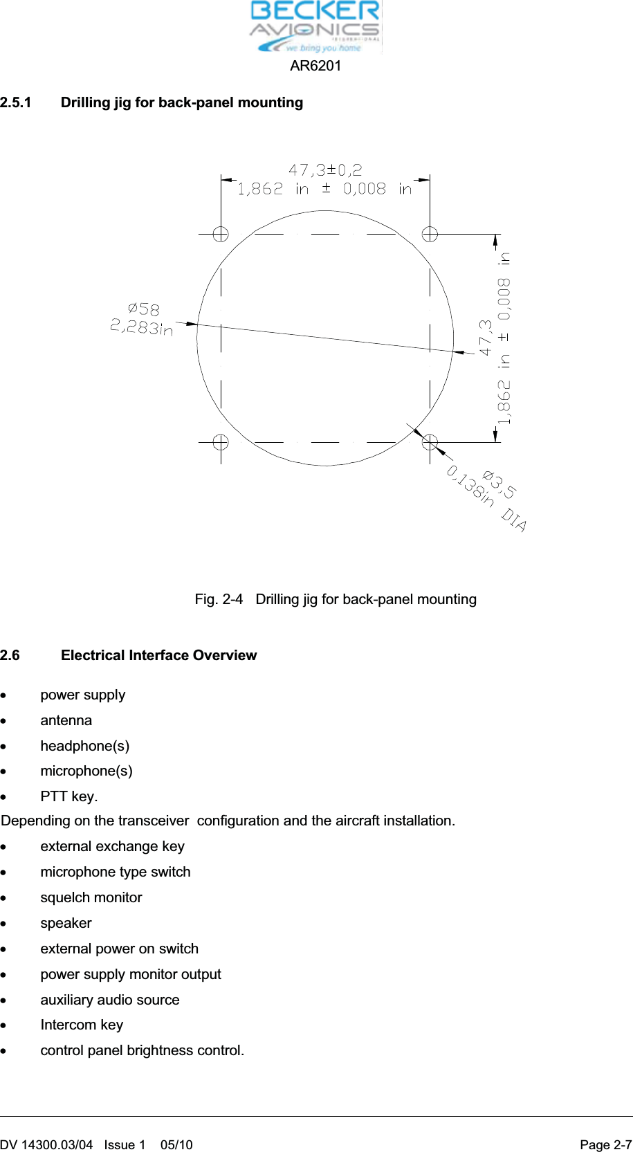
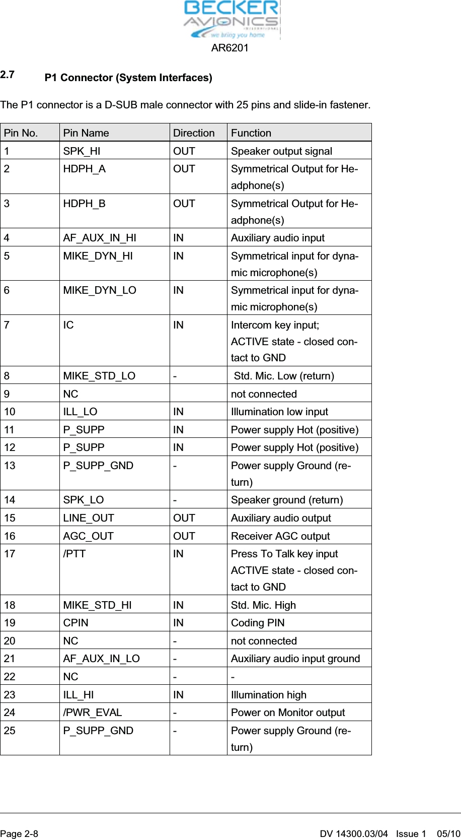
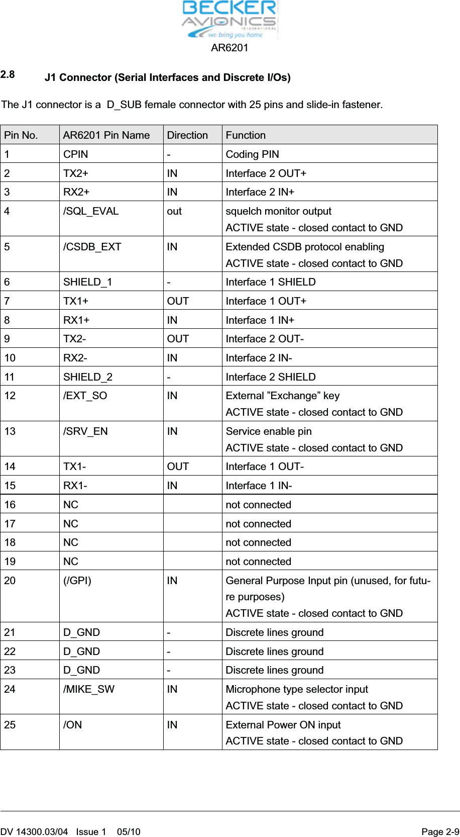
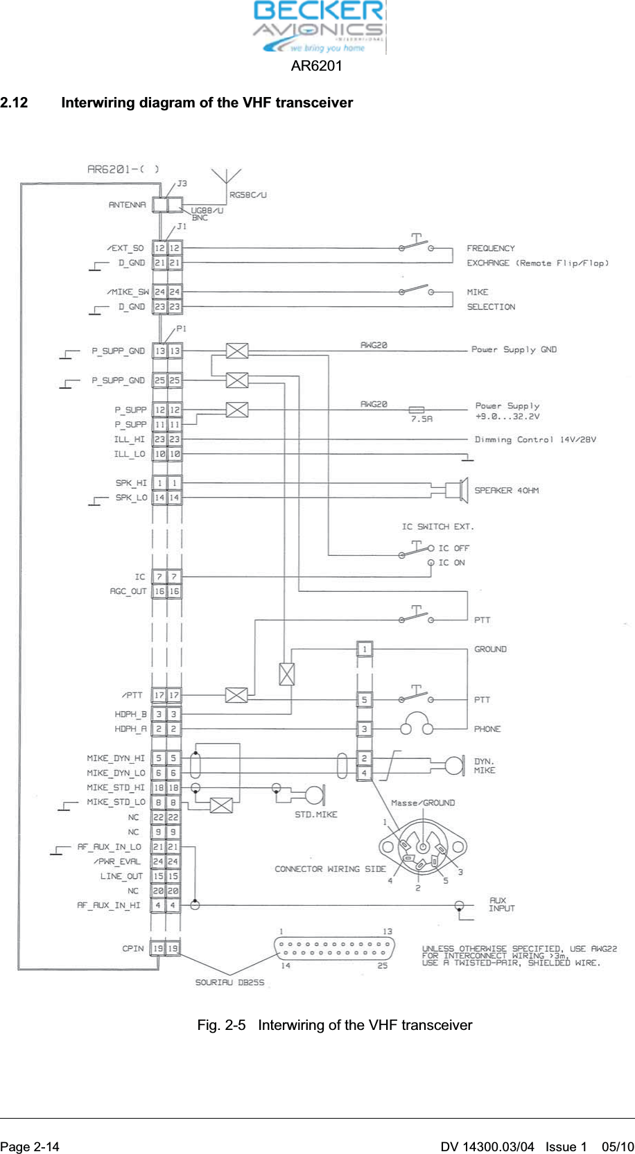
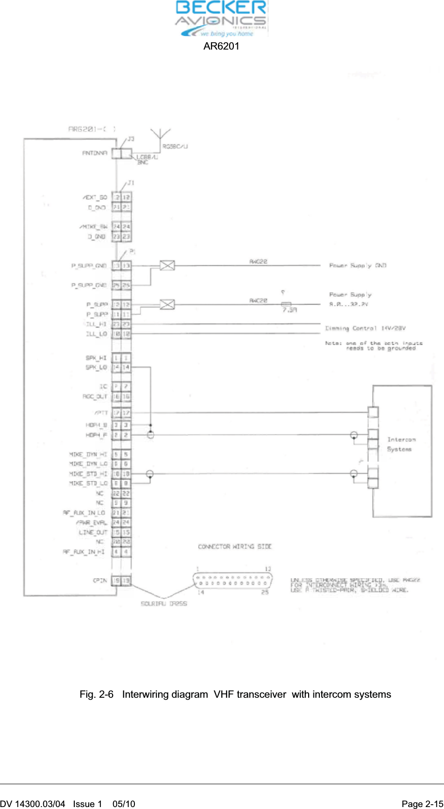
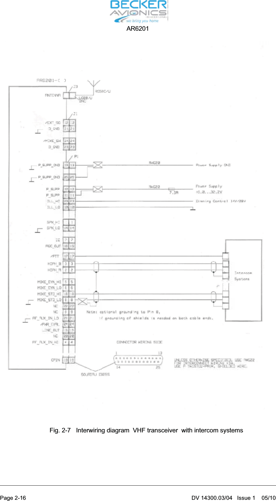
Installation instrauctions

Installation and OperationManual DV 14300.03Issue 1 May 2010Becker Flugfunkwerk GmbH ·Baden Airpark ·77836 Rheinmünster ·GermanyTelephone +49 (0) 7229 / 305-0 ·Fax +49 (0) 7229 / 305-217http://www.becker-avionics.com ·e-mail: info@becker-avionics.deVHF-TransceiverAR6201-(XXX)
FIRST ISSUE AND CHANGESIssue 1 May 2010LIST OF EFFECTIVE PAGESPage No.: Date : Page No.: Date :Cover page1 -I - 1-II1-1 - 1-102-I - 2-II2-1 - 2-183-I - 3-II3-1 - 3-1605/201005/201005/201005/201005/201005/201005/2010DV 14300.03 / Article Number 0617.857-071© 2010 by Becker Flugfunkwerk GmbH / All rights reserved
Table of contentsSection I General Description Page1.1 Introduction 1-11.2 Purpose of equipment 1-11.3 General description 1-11.4 Variants survey 1-31.5 Technical data 1-41.5.1 Power supply data 1-41.6 General data 1-41.6.1 Dimensions Weight 1-41.6.2 Receiver data 1-51.6.3 Transmitter data 1-51.6.4 Software EUROCAE ED-12B/RTCA DO-178B Level D 1-61.7 Approval 1-61.8 Environmental Qualification 1-71.9 Accessories 1-9AR6201DV 14300.03/.04 Issue 1 05/10 Page 1-I
BlankAR6201Page 1-II DV 14300.03/.04 Issue 1 05/10
Section I GENERAL DESCRIPTION1.1 IntroductionThis manual describes the VHF transceiver AR6201-(XXX). The manuals DV 14300.03 (“Installationand Operation”) and DV 14300.04 (“Maintenance and Repair”) contain the following sections.Section DV 14300.03 DV 14300.041General Information XX2Installation XX3Operation XX4Theory of operation N/A X5Maintenance and Repair N/A X6Illustrated Parts List N/A X7Modification and Changes N/A X8Circuit Diagrams N/A x1.2 Purpose of equipmentThe VHF transceiver enables voice communication in the very high frequency band between118.000 MHz to 136.990 MHz (radio communication part of airband) with a channel spacing of 25 kHzin 25 kHz mode and with 8.333 kHz channel spacing in 25+8.33 kHz mixed mode.1.3 General descriptionThe VHF transceiver is designed without any verified environmental class restrictions. It can be fittedin the instrument panel of all aircraft types.The VHF transceiver can be fully remote controlled via a RS422 interface and the industry establishedCommercial Serial Data Bus protocol.DV 14300.03/04 Issue 1 05/10 Page 1-1AR6201
Configuration of the system is possible by means of a dedicated service interface implemented as aRS422 interface line with a proprietary serial data communication protocol.The VHF transceiver is a compact and lightweight single block unit. The dimensions correspond to thestandard instrument diameter of 58 mm (2 1/4 inch). Mounting is by means of four screws (rear panelmounting). All controls and indicators are located on the front panel. The equipment connectors andthe antenna socket are located at the rear of the unit.After switch on, the unit performs a self test (PBIT). After the PBIT the transceiver shows “WAIT” andthe corresponding software versions of the control head and chassis module. If the PBIT detects a fatalerror, the transceiver terminates operation and will be locked.The transmitter is designed for the 118.000 MHz to 137.000 MHz frequency range. The sidetone isavailable on the headphone output during transmission. The sidetone level can be set in the servicemenu.The frequency indication is by means of a liquid crystal display (LCD). The required operating frequen-cy is set with the frequency selector switch. The pushbutton selects the digits.Memory channelsThe VHF transceiver also contains a memory device for storing 99 different frequencies which remainstored even with the unit switched off without an auxiliary battery. Last 9 frequencies are stored auto-matically.Mike inputsThe VHF transceiver has an input for dynamic microphone (DYN_MIKE) and an input for standard mi-crophone (STD_MIKE). Each input is able to operate with single microphone or with 2 microphones ofthe same type connected in parallel.AF auxiliary inputThe AF auxiliary input enables AF signal switching of auxiliary units in the aircraft. The switched AF sig-nals can be monitored in the reception mode only .Audio outputsThe Headphone rated output power is ³300 mW @ 150 Ohm.The transceiver includes a speaker output (SPK). The rated output power from the Speaker Output ismin.4W@4OhmThe transceiver has an asymmetrical LINE output (LINE_OUT). When the transceiver is operating inRX mode the line output supplies the sum of intercom audio, receiver audio and auxiliary audio.Whenthe transceiver is operating in TX mode, then the LINE output supplies the natural sidetone.Intercom modeAircraft internal communication is possible in the intercom mode (IC). The intercom mode is activatedby a long press of the SQL/IC button.Squelch OperationThere are two kinds of squelch methods implemented. The carrier squelch (C_Squelch) and noisesquelch (N_Squelch). The carrier squelch is based on received signal strength; the noise squelch isbased on noise level detected in demodulated received signal.Page 1-2 DV 14300.03/04 Issue 1 05/10AR6201
Scan sub modeThe scan sub-mode is activated by a long press of the EXCHANGE/SCAN key in all selection modes.IlluminationThe VHF transceiver include a dimming input that controls illumination of LCD and push buttons. Thedimming entry is either 14V AC/DC or 28V DC.The illumination can be dimmed from off to full illumination.The display has minimum illumination to en-sure that the indicators are always visible.The characteristic of the dimming and illumination curve can be adapted to other units in the instrumentpanel in the service mode. The unit setup enables selection value of display contrast in range of 0 …100 %.Monitoring stage for the power supply voltageThe VHF transceiver also contains a monitoring stage for the power supply voltage which is activatedwhen the VHF transceiver is switched on. If the supply voltage drops below 10.5 V (Low BatteryThreshold), the display indicates the message “LOW BATT”.Emergency operationIn emergency operation the following performance reduction is possible i.e. when the supply voltagedropped down to 9 V.pFor TX Mode: RF Rated power is ³2W@50Ohm, modulation depth is ³50 %,pFor RX Mode: (S+N)/N ³6 dB for RF level -93 dBm, m = 30% 1 kHz sine1.4 Variants surveyType designationPart-No.:Nominal supplyvoltageTransmitteroutputPanel lighting Panel colourVHF Transceiver single blockGreen AR6201-(000)Article Nr.: 0610.321-91013.75 V ³6W 13.75 V /27.5 VblackVHF Transceiver single block-Blue-White AR6201-(002)Article Nr.: 0614.203-91013.75 V ³6W 13.75 V /27.5 VblackDV 14300.03/04 Issue 1 05/10 Page 1-3AR6201
1.5 Technical data1.5.1 Power supply dataNominal supply voltage 13.75 V DCSupply voltage range 9.0 V … 32.2V DCEmergency operation 9.0 V DC … 10.25 V DCPower consumptionPower off state £0.1 mAReception mode £140 mATransmission mode £2 A TX mode m ³70 %£1.8A@12VDC; TX Carrier unmodulated£4A@14VDC; Antenna VSWR = 3:1DC-Fuse internal 5 A (resettable)Dimming control 13.75 V DC or 27.5 V DC1.6 General dataFrequency range 118.000 MHz to 136.975 MHz for 25 kHzFrequency range 118.000 MHz to 136.990 MHz for 8.333 kHzChannel spacing 25 kHz or 8.333 kHzNummber of channels 760 (25 kHz) / 2278 (8.333 kHz)Storage temperature range -55 °C to +85 °COperating temperature range as perEUROCAE/RTCA ED-14E/DO-160E -20 °C to + 55 °Cshort-time + 70 °COperating altitude as perEUROCAE/RTCA ED-14E/DO-160E 35,000 ftVibration as perEUROCAE/RTCA ED-14E/DO-160E Cat. S+U1.6.1 Dimensions weightFront panel 61.2 mm x 61.2 mmDepth of unit without 208.3 mmcable connectorMounting (backpanel) standard 58 mm diameter (21/4 inch)Material of Case, surface treatment ALMg, blankcoated black matt paintWeight £800 gAR6201Page 1-4 DV 14300.03/04 Issue 1 05/10
1.6.2 Receiver dataSensitivity -93 dBm for a (S+N)/N ratio of 6 dB(mod. 1000 Hz/30%)Effective bandwidth ³±3 kHz at the 6 dB points£±7.37 kHz at the 60 dB pointsSquelch Can be adjusted to any trigger level orswitched offAGC characteristic for £6 dB mod. 30% 1000 Hz-93 dBm to 0 dBmDistortionm=85% £15%Audio frequency response £6 dB 350 Hz to 2500 Hzrelative to 1000 Hz ³35 dB at 4000 HzRated outputfor speaker operation ³4Winto4WRated output powerfor headphone operation ³300 mW into 150 W³100 mW into 600 WAudio auxiliary input 1 V to8Vat600W± 10%adjustable (regardless of volume setting)1.6.3 Transmitter dataTransmitter output ³6 W into 50 WFrequency tolerance £5 ppmDuty cycle 1:4 (Min)Type of modulation A3E (amplitude modulation)Modulation capability ³70%Distortion at 70% modulation £15%Modulation bandwidth £6 dB 350 Hz to 2500 HzDynamic microphone 1 … 20 mV balanced (200 W)(dynamic compressor)Standard microphone 10 mV ..... ³1 V (150 W)(dynamic compressor)AR6201DV 14300.03/04 Issue 1 05/10 Page 1-5
FM deviation with modulationm=70%f=25kHz/8.33 kHz £3 kHzSidetone adjustableAutomatic shutdown on transmit after 30 seconds ... 120 seconds of conti-mode nuous transmission, the transmitter shutsdown1.6.4 Software EUROCAE ED-12B/RTCA DO-178B Level DThe frequency processing, frequency storage and frequency indication are controlled by microproces-sors. The software is classified as Category “MINOR” Level D in accordance with EUROCAE/RTCADocument ED12B/DO-178B.1.7 ApprovalETSO pendingPage 1-6 DV 14300.03/04 Issue 1 05/10AR6201
1.8 Environmental QualificationThe following performance standards under environmental test conditions have been established inaccordance with the procedures set forth in EUROCAE/RTCA Document ED-14E/DO-160E.Condition Section Cat. DescriptionTemperature and Altitude 4.0 C4Ground Survival Low Temperature 4.5.1 -55 deg CShort-Time Operating LowTemperature-20 deg COperating Low Temperature -20 deg CHigh Ground Survival Temperature 4.5.2 +85 deg CHigh Short-Time Operating Temp. 4.5.3 +70 deg COperating High Temp. 4.5.4 +55 deg CIn-flight Loss of Cooling 4.5.5 X No forced cooling requiredAltitude 4.6.1 C4 35,000 ftDecompression 4.6.2Overpressure 4.6.3Temperature Variation 5.0 B 5°C per minuteHumidity 6.0 A StandardShock and Crash Safety 7.0 B Fixed-wing and Helicopter, standardVibration 8.0 SUCurve M for Fixed-wing AircraftCurve G for HelicoptersExplosion proofness 9.0 X N/AWater proofness 10.0 X N/AFluids Susceptibility 11.0 X N/ASand and Dust 12.0 X N/AFungus Resistance 13.0 X N/ASalt Spray 14.0 X N/AMagnetic Effect 15.0 Z Less than 0.3mPower Input 16.0 B DC installations with battery of signi-ficant capacityVoltage Spike 17.0 A High degree of protection againstvoltage spikesDV 14300.03/04 Issue 1 05/10 Page 1-7AR6201
Condition Section Cat. DescriptionAudio Freq. Conducted Susceptibility 18.0 B DC installations with battery of signi-ficant capacityInduced Signal Susceptibility 19.0 AC Primary power DC or AC, 400HzRadio Frequency Susceptibility 20.0 WS Interim High Intensity RadiatedFieldsEmission of Radio Frequency Energy 21.0 B Equipment where interferenceshould be controlled to a tolerablelevelLightning Induced Transients Suscepti-bility22.0 A1E3X Pin test waveform A, level 1Cable bundle test waveform E,level 3Lightning Direct Effects 23.0 X N/AIcing 24.0 X N/AElectrostatic Discharge 25.0 A Equipment operated in an aerospaceenvironmentFire, Flammability 26.0 X N/AAR6201Page 1-8 DV 14300.03/04 Issue 1 05/10
1.9 AccessoriesConnector Kit CK4201-S (soldering version) Article-No.: 0879.304-954consisting of25-pol. cable connector, soldering F Article no. 0725.021-277Connector housing Article no. 0775.479-277Antenna plug Article no. 0725.706-277Label “COMM” Article no. 0711.111-258Connector Kit CK4201-C (crimp version) Article-No.: 0514.901-954consisting of25-pol. cable connector, crimp F Article no. 0472.921-277Connector housing Article no. 0775.479-277Antenna plug Article no. 0725.706-277Label “COMM” Article no. 0711.111-258Connector Kit CK6200-S (soldering version) Article-No.: 0617.903-954consisting of25-pol. cable connector, soldering F Article no. 0725.021-27725-pol. cable connector, soldering M Article no. 0726.331.2772 X Connector housing Article no. 0775.479-277Antenna plug Article no. 0725.706-277Label “COMM” Article no. 0711.111-258AR6201DV 14300.03/04 Issue 1 05/10 Page 1-9
Connector Kit CK6200-C (crimp version) Article-No.: 0617.891-954consisting of25-pol. cable connector, crimp F Article no. 0472.921-27725-pol. cable connector, crimp M Article no. 0891.551-2772 X Connector housing Article no. 0775.479-277Antenna plug Article no. 0725.706-277Label “COMM” Article no. 0711.111-258DocumentationOperating instructions Article no. 0618.764-071Manual Installation and Operation Article no. 0617.857-071Manual Maintenance and Repair Article no. 0617.865-071Page 1-10 DV 14300.03/04 Issue 1 05/10AR6201
Ta ble of con tentsSec tion 2 IN STAL LA TION Page2.1 Ge ne ral 2-12.2 Te sting be fo re in stal la ti on 2-12.3 Me cha ni cal in stal la ti on 2-12.3.1 Me cha ni cal in stal la ti on of VHF trans cei ver. 2-12.4 In stal la ti on wi ring 2-22.4.1 Ge ne ral 2-22.4.2 Mi cro pho ne con nec ti on 2-22.4.3 Spea ker con nec ti on 2-32.4.4 He adpho ne con nec ti on 2-32.4.5 In ter com mode “IC con nec ti on” 2-32.4.6 Pa nel lighting 2-42.4.7 “Au xi lia ry” au dio in put 2-42.4.8 LINE out put 2-52.4.9 In ter nal au to ma tic fuse (re se ta ble) 2-52.5 Di men sions VHF trans cei ver 2-62.5.1 Dril ling jig for back-panel moun ting 2-72.6 Elec tri cal In ter fa ce Over view 2-72.7 P1 Con nec tor (Sy stem In ter fa ces) 2-82.8 J1 Con nec tor (Se ri al In ter fa ces and Di scre te I/Os) 2-92.9 An ten na con nec tor 2-102.10 Trans cei ver groun ding 2-102.11 Ser vi ce mode 2-102.12 In ter wi ring dia gram of the VHF trans cei ver 2-142.13 Te sting af ter in stal la ti on 2-172.13.1 Ground test with en gi ne shut down 2-172.13.2 Ground test with en gi ne run ning 2-17Fig. 2-1 In ter wi ring pa nel lighting 2-4Fig. 2-2 Lo ca tion of au to ma tic fuse (re se ta ble) 2-5Fig. 2-3 Moun ting di men sions VHF trans cei ver 2-6Fig. 2-4 Back-pa nel moun ting 2-7Fig. 2-5 In ter wi ring of the VHF trans cei ver 2-14Fig. 2-6 In ter wi ring dia gram  VHF trans cei ver  with in ter com sys tems 2-15Fig. 2-7 In ter wi ring dia gram  VHF trans cei ver  with in ter com sys tems 2-16AR6201DV 14300.03/.04   Is sue 1     05/10 Page 2-I
BlankAR6201Page 2-II DV 14300.03/.04   Is sue 1     05/10
Sec ti on 2 IN STAL LA TI ON2.1 Ge ne ralThe in stal la ti on of the VHF trans cei ver de pends on the type of air craft and its equip ment. The re fo re,only ge ne ral in for ma ti on can be gi ven in this sec tion.No ti ce:Chan ges or mo di fi ca tions made to this equip ment not ex press ly ap pro ved by Be cker Flug -funk werk may void the aut ho ri za tion to ope ra te this equip ment.2.2 Te sting be fo re in stal la ti onGe ne ralBe fo re in stal ling the VHF trans cei ver in an air craft, in spect the unit for signs of trans port da ma ge.Vi su al exa mi na ti onBe fo re com mis sio ning, vi su al ly exa mi ne the unit pay ing par ti cu lar at ten ti on to the fol lo wing:(1) Dirt, dents, scrat ches, cor ro si on or bro ken at ta ching parts, da ma ged paint work on hou sing,parts of the hou sing and pa nel.(2) Dirt or scrat ches on the iden ti fi ca ti on pla te, front pa nel, LCD or ins crip tions.(3) Dirt, bent or bro ken pins, dis pla ced in serts of plugs and so ckets.(4) Dirt and me cha ni cal da ma ge to push  but tons and ope ra ting knobs.2.3 Me cha ni cal in stal la ti on2.3.1 Me cha ni cal in stal la ti on of VHF trans cei ver.The VHF trans cei ver is de sig ned for in stal la ti on in the in stru ment pa nel of an air craft. It is con struc tedfor moun ting be hind the pa nel. The cir cu lar cu tout and the moun ting ho les are to be dril led in ac cor dan-ce with the  in stru ment size. The moun ting point shall be at least 30 cm away from the air craft mag ne ticcom pass, to avoid any in ter fe ren ce to the mag ne tic com pass by the trans cei ver. The ne ces sa ry di -men sions are gi ven in Fig. 2-3. At tach ment is by me ans of four screws, which are in clu ded in the de li-very.AR6201DV 14300.03/04   Issue 1    05/10 Page 2-1
2.4 In stal la ti on wi ring2.4.1 Ge ne ralThe in stal la ti on wi ring dia grams are shown in Fig. 2-5 to 2-7.Note :(1) Use only ca ble which is fit for air craft use (self ex tingu is hing). AWG 20 for po wer supp lyand AWG 22 for ot her ca bles.(2) Fit slee ves over the sol der joints on the equip ment con nec tor.(3) Pro tect the po wer supp ly with a 7.5 A fuse or cir cuit brea ker.Note :The VHF trans cei ver is pro tec ted in ter nal ly by a 5 A re se ta ble fuse.(4) Type-spe ci fic ca ble har nes ses are also avai la ble for the air craft wi ring (de tails from thema nu fac tu rer).(5) No HF ca bles should be in clu ded in the ca ble har nes ses of the sys tem. The rou ting ofcon nec ting ca bles along si de ca bles which car ry au dio po wer or pul ses should also be avoi ded.(6) Ca re ful ly check the wi ring be fo re swit ching on the unit and check par ti cu lar ly that (+) and (-)have not been re ver sed.2.4.2 Mi cro pho ne con nec ti onStan dard (car bon) mi cro pho ne For stan dard (car bon) mi cro pho ne ope ra ti on mode the trans cei ver has  an asym me tric in put with anin put re sis tan ce of 150 Ohm and a no mi nal sen si ti vi ty of 250 mV. This can be chan ged in the ser vi cemode  from 10 mV to 1 V. The po wer supp ly for stan dard mi cro pho ne is dc supp ly vol ta ge (open cir cuit)10.5 V, feed re sis tan ce 470 Ohm.MIKE EXT (HI) Pin 18 Mi cro pho ne In putMIKE EXT (LO) Pin 8 Mi cro pho ne In putDy na mic mi cro pho neFor dy na mic mi cro pho ne ope ra ti on mode, the transceiver has  a ba lan ced in put  with an im pe dan ce of200 Ohm in put re sis tan ce and a no mi nal sen si ti vi ty of 2 mV. This can be chan ged in the ser vi ce modefrom 1 to 20 mV.MIKE EXT (HI) Pin 5 Mi cro pho ne In putMIKE EXT (LO) Pin 6 Mi cro pho ne In putAR6201Page 2-2 DV 14300.03/04   Issue 1    05/10
The VHF trans cei ver en ab les a ma xi mum of two dy na mic mi cro pho nes or  two stan dard mi cro pho nes(d.c. supp ly) to be con nec ted at the same time.  For con nec ti on bet ween the trans cei ver and any mi -cro pho ne in put lon ger than 1.5 m, ground loop shall be avoi ded.2.4.3 Spea ker con nec ti onA 4 Ohm spea ker can be con nec ted to au dio out put con nec tor P1 pin 1 and pin 14.Speaker Pin 1 Spea ker AF sig nalGND Pin 14 Sig nal groundCAU TI ON :The mag ne tic field of a spea ker in flu en ces the mag ne tic compass. When choo sing the moun ting point,a di stan ce of not ef fec ting the mag. Com pass must be de ter min ed.  Af ter spea ker in stal la tio na com -pass swing must be performed.2.4.4 He adpho ne con nec ti onUp to two he adpho nes with an im pe dan ce of 600 Ohm can be con nec ted to the au dio out put con nec torP1 pin 2 and pin 3.Pho ne Pin 2 He adpho nes AF sig nalGND Pin 3 Sig nal ground2.4.5 In ter com mode “IC con nec ti on”.The in ter com mode is de sig ned for air craft with a high noi se le vel and as su mes ope ra ti on using he ad-sets. When the in ter com mode is set to ON, R/T com mu ni ca ti on can be car ried on but in ter com mu ni ca-ti on is also pos si ble bet ween two crew mem bers. The IC is swit ched off du ring trans mis si on.IC Vo lu me can be ad jus ted by a ”Long press” of ”IC/SQL” key and then tur ning the ro ta ry en co der,possible in all mo des, in clu ding scan mode but ex ept du ring TX mode.The VOX set ting is ac ti vat ed by a  ”Short press” of ”IC/SQL” key or by pres sing the ”ro ta ry en co der” du -ring IC Vo lu me set tings.AR6201DV 14300.03/04   Issue 1    05/10 Page 2-3
2.4.6 Pa nel lightingThe VHF trans cei ver is fit ted with pa nel lighting. It is to be con nec ted to the air craft ex ter nal po wersupp ly via the air craft wi ring.For 0…14 V dim ming vol ta ge ran ge con nect ILL_HI (pin 23)  to dim ming vol ta ge bus and ILL_LO (pin10) to sys tem ground (P_SUPP_GND)  (re fer to the fol lo wing il lu stra ti on).CAU TI ON :The lighting is not swit ched off when the unit is swit ched off (ON/OFF switch)Fig. 2-1   In ter wi ring pa nel lightingFor 0…28 V dim ming vol ta ge ran ge con nect ILL_LO (pin 10) to dim ming vol ta ge bus and ILL_HI  (pin23) to sys tem ground (P_SUPP_GND).2.4.7 “Au xi lia ry” au dio in putThe AF-AUX (P1/4) au xi lia ry au dio in put en ab les the mo ni to ring of au dio sig nals from ot her equip mentin the air craft. These au dio sig nals are mo ni to red in the re cep ti on mode only. The fa ci li ty to switch twounits to get her will be used par ti cu lar ly in tho se air craft which are fit ted with a Trans cei ver and a NAV re -cei ver. An au dio in put vol ta ge of 1 to 8 V, 600 Ohm is ne ces sa ry for mo du la ti on of the au dio am pli fier(can be ad jus ted in the “Ser vi ce” mode).AF AUX Pin 4 Au xi lia ry au dio in putGND Pin 21 Au xi lia ry au dio groundAR6201Page 2-4 DV 14300.03/04   Issue 1    05/1013131212
2.4.8 LINE out putThe trans cei ver has an asym me tric  AF bro ad band  Out put (AC cou pled). The RX AF-sig nal from thetrans cei er is pre sent at this out put. The out put le vel  = 1 VRMS ± 0.2 V 1k Ohm.2.4.9 Lo ca tion of in ter nal au to ma tic fuse (re se ta ble)The in ter nal au to ma tic fuse is re ac ti vat ed by me ans of a mat ching pla stic tool (self made).Fig. 2-2 Lo ca tion of in ter nal au to ma tic fuse (re se ta ble)AR6201DV 14300.03/04   Issue 1    05/10 Page 2-5
2.5 Di men sions VHF trans cei verFig. 2-3   Moun ting di men sions VHF trans cei verAR6201Page 2-6 DV 14300.03/04   Issue 1    05/10
2.5.1 Dril ling jig for back-pa nel moun tingFig. 2-4   Dril ling jig for back-pa nel moun ting2.6 Elec tri cal In ter fa ce Over view•po wer supp ly•an ten na•he adpho ne(s)•mi cro pho ne(s)•PTT key.De pen ding on the trans cei ver  con fi gu ra ti on and the air craft in stal la ti on.•ex ter nal ex chan ge key•mi cro pho ne type switch•squelch mo ni tor•spea ker•ex ter nal po wer on switch•po wer supp ly mo ni tor out put•au xi lia ry au dio sour ce•In ter com key•con trol pa nel bright ness con trol.AR6201DV 14300.03/04   Issue 1    05/10 Page 2-7
2.7 P1 Con nec tor (Sy stem In ter fa ces)The P1 con nec tor is a D-SUB male con nec tor with 25 pins and sli de-in fas te ner.Pin No. Pin Name Di rec ti on Functi on1 SPK_HI OUT Spea ker out put sig nal2 HDPH_A OUT Sym me tri cal Out put for He -adpho ne(s)3 HDPH_B OUT Sym me tri cal Out put for He -adpho ne(s)4 AF_AUX_IN_HI IN Au xi lia ry au dio in put5 MIKE_DYN_HI IN Sym me tri cal in put for dy na-mic mi cro pho ne(s)6 MIKE_DYN_LO IN Sym me tri cal in put for dy na-mic mi cro pho ne(s)7 IC IN In ter com key in put;AC TI VE sta te - clo sed con -tact to GND8 MIKE_STD_LO -  Std. Mic. Low (re turn)9 NC not connected10 ILL_LO IN Il lu mi na ti on low in put11 P_SUPP IN Po wer supp ly Hot (po si ti ve)12 P_SUPP IN Po wer supp ly Hot (po si ti ve)13 P_SUPP_GND - Po wer supp ly Ground (re -turn)14 SPK_LO - Spea ker ground (re turn)15 LINE_OUT OUT Au xi lia ry au dio out put16 AGC_OUT OUT Re cei ver AGC out put17 /PTT IN Press To Talk key in putAC TI VE sta te - clo sed con -tact to GND18 MIKE_STD_HI IN Std. Mic. High19 CPIN IN Co ding PIN20 NC - not con nec ted21 AF_AUX_IN_LO - Au xi lia ry au dio in put ground22 NC - -23 ILL_HI IN Il lu mi na ti on high24 /PWR_EVAL - Po wer on Mo ni tor out put25 P_SUPP_GND - Po wer supp ly Ground (re -turn)AR6201Page 2-8 DV 14300.03/04   Issue 1    05/10
2.8 J1 Con nec tor (Se ri al In ter fa ces and Di scre te I/Os)The J1 con nec tor is a  D_SUB fe ma le con nec tor with 25 pins and sli de-in fas tener.Pin No. AR6201 Pin Name Di rec ti on Functi on1 CPIN - Co ding PIN2 TX2+ IN In ter fa ce 2 OUT+3 RX2+ IN In ter fa ce 2 IN+4 /SQL_EVAL out squelch mo ni tor out putAC TI VE sta te - clo sed con tact to GND5 /CSDB_EXT IN Ex ten ded CSDB pro to col en ab lingAC TI VE sta te - clo sed con tact to GND6 SHIELD_1 - In ter fa ce 1 SHIELD7 TX1+ OUT In ter fa ce 1 OUT+8 RX1+ IN In ter fa ce 1 IN+9 TX2- OUT In ter fa ce 2 OUT-10 RX2- IN In ter fa ce 2 IN-11 SHIELD_2 - In ter fa ce 2 SHIELD12 /EXT_SO IN Ex ter nal ”Ex chan ge” keyAC TI VE sta te - clo sed con tact to GND13 /SRV_EN IN Ser vi ce en ab le pinAC TI VE sta te - clo sed con tact to GND14 TX1- OUT In ter fa ce 1 OUT-15 RX1- IN In ter fa ce 1 IN-16 NC not con nec ted17 NC not con nec ted18 NC not con nec ted19 NC not con nec ted20 (/GPI) IN Ge ne ral Pur po se In put pin (un used, for fu tu-re pur po ses)AC TI VE sta te - clo sed con tact to GND21 D_GND - Di scre te li nes ground22 D_GND - Di scre te li nes ground23 D_GND - Di scre te li nes ground24 /MIKE_SW IN Mi cro pho ne type se lec tor in putAC TI VE sta te - clo sed con tact to GND25 /ON IN Ex ter nal Po wer ON in putAC TI VE sta te - clo sed con tact to GNDAR6201DV 14300.03/04   Issue 1    05/10 Page 2-9
2.9 An ten na con nec torBayo net Nut Con nec tor (BNC 50 Ohm).2.10 Trans cei ver groun dingThe trans cei ver in clu des a groun ding bolt (M4 thre aded bolt).2.11 Ser vi ce modeThe ser vi ce mode is me ant to en ab le the ground tech ni ci ans to set the equip ment con fi gura ti on andmust not be used in flight. The ser vi ce mode is ac ti vat ed when the MDE key is pres sed whi le the trans -cei ver  is swit ched ON.”SE TUP” is in di ca ted on the screen, press any key en ter the ser vi ce mode.Se tup in di ca tionSet the  4-digit nu me ri cal code pass word “6435” using  ”ro ta ry en co der” and push but ton of the ”ro ta-ry en co der” and con firm by pus hing the ”STO” but ton.Pass word Dia logAR6201Page 2-10 DV 14300.03/04   Issue 1    05/10
Push ”ro ta ry en co-der”Turn ”ro ta ry en co der” Ope ra ting View and Con di tionsAR6201  INFO CH-SW(Con trol Head CH)CM-SW(chas sis mo du le CM)SN(Se ri al Num ber)View onlyDim ming input None0 - 14 V DC0 - 28 V DCPush STO key willac ti va te the se lec-ted op ti onBRIGHT NESS 0%...50%...100% Ad just ment is sto-red au to ma ti cal lywit hout pus hingSTO keyDis play ed only if Dim ming in putis set to  ”NONE”IL LUM CUR VE Cha rac te ris tic  points:A - Mi ni mum Il lu mi na ti onB – Ma xi mum Il lu mi na ti on)Y - Mi ni mum Dim ming Vol ta-geZ - Ma xi mum Dim ming Vol ta-geAd just ment is sto-red au to ma ti cal lywit hout pus hingSTO keyDis play ed only if Dim ming in putdif fe rent than ”NONE”14V or 28V is dis play ed de pen-ding on se lec ti onEN AB LE  STO RE En ab le Sto re Pus hing STO key ac ti va tes the se -lec ted op ti onERA SE_MEM(Era se me mo ry chan -nels for se lec ted chan -nel spa cing only)NOYESPus hing STO keyac ti va tes the se -lec ted op ti onCON FIG En ab le Spea kerEn ab le AF_AUX_INEn ab le SCAN BEEPAu to ma tic AUX mutePus hing STO keyis tog gle ON/OFFthe se lec ted va ria-bleAR6201DV 14300.03/04   Issue 1    05/10 Page 2-11BRIGHTNESS50%DIMMING INONONE?0-14VO0-28V
Push ”ro ta ry en co-der”Turn ”ro ta ry en co der” Ope ra ting View and Con di tionsAF_AUX_IN SEN SI TI-VI TY1.0..8.0V,step 0.1VAd just ment is sto -red au to ma ti cal lywit hout pus hingSTO keyDis play ed only if AF_AUX_IN  En ab ledMIKE TYPE HARD WA RE SE LEC TI ONIN VER TED HARD WA RESE LEC TI ONSTD MIKEDYN MIKEMI XEDAd just ment is sto -red au to ma ti cal lywit hout pus hingSTO keySTD MIKE SEN SI TI VI-TY10..1000 mV, in 10 mV steps Ad just ment is sto -red au to ma ti cal lywit hout pus hingSTO keyDis play ed if  MI XED orSTD_MIKE Type is cho -sen by soft wa re or MikeType is set to hard wa rese lec ti on and STD_MIKEis se lec ted on ex ter nal pinDYN MIKE SEN SI TI VI-TY1.0..20.0 mV in 0.2 mV stepAd just ment is sto -red au to ma ti cal lywit hout pus hingSTO keyDis play ed if  MI XED orDYN_MIKE Type is cho sen bysoft wa re or Mike Type is set tohard wa re se lec ti on and DYNMike is se lec ted on ex ter nal pinSNR SQUELCHTHRES HOLD6 ... 12 dB Ad just ment is sto-red au to ma ti cal lywit hout pus hingSTO keyCO SQUELCH THRES HOLD-95 ... -85 dBm Ad just ment is sto-red au to ma ti cal lywit hout pus hingSTO keyPage 2-12 DV 14300.03/04   Issue 1    05/10AR6201
Push ”ro ta ry en co-der”Turn ”ro ta ry en co der” Ope ra ting View and Con di tionsSCAN HOLD TIME 1..60 s Ad just ment is sto-red au to ma ti cal lywit hout pus hingSTO keyLOW BAT TE RYTHRES HOLD10.0 ... 33.0 V, step 0.1 V Ad just ment is sto-red au to ma ti cal lywit hout pus hingSTO keySI DE TO NE ATT 0…12dB Ad just ment is sto-red au to ma ti cal lywit hout pus hingSTO keyAR ER ROR LATCH PBIT and CBIT Fai lu re Listac cor ding /BIT/View onlyERA SE FAIL LIST(LAT CHES)NOYESPus hing STO key ac ti va tes the se -lec ted op ti onRE CALL DE FAULT (FAC TO RY)NOYESPus hing STO keyac ti va tes the se -lec ted op ti onTo re turn from ser vi ce mode the de vi ce must be tur ned OFF and ON again.AR6201DV 14300.03/04   Issue 1    05/10 Page 2-13
2.12 In ter wi ring dia gram of the VHF trans cei verFig. 2-5   In ter wi ring of the VHF trans cei verAR6201Page 2-14 DV 14300.03/04   Issue 1    05/10
Fig. 2-6   In ter wi ring dia gram  VHF trans cei ver  with in ter com sy stemsAR6201DV 14300.03/04   Issue 1    05/10 Page 2-15
Fig. 2-7   In ter wi ring dia gram  VHF trans cei ver  with in ter com sy stemsAR6201Page 2-16 DV 14300.03/04   Issue 1    05/10
2.13 Te sting af ter in stal la ti on2.13.1 Ground test with en gi ne shut down.Af ter in stal la ti on of the unit, mea su re the an ten na tu ning bet ween the base of the an ten na and the an -ten na con nec ting ca ble using a VHF re flec ti on-co ef fi cient me ter (vol ta ge stan ding wave me ter).The VSWR (vol ta ge stan ding wave ra tio) over the com ple te fre quen cy ran ge of the unit shall be wit hin3:1. If this mat ching va lue is ex cee ded it in di ca tes a mis match, cau sed for ex am ple by an in cor rect orunsatis fac to ry coun ter poi se, a ca ble with an im pe dan ce which de via tes sig ni fi cant ly from 50 Ohm oran in cor rect ly tu ned an ten na, or faults on the BNC con nec tors of the an ten na cable.2.13.2 Ground test with en gi ne run ning.With the en gi ne run ning at crui sing speed check that the air craft po wer supp ly is wit hin the per mis si bleto le ran ces at ap pro xi ma te ly 14 V.When per for ming a com mu ni ca tion test, en su re that the dis tan ce from the ground sta ti on is as great aspos si ble, at least 100 m. With the en gi ne at crui sing speed, the ca bin noi se of the air craft should beonly slight ly trans mit ted and com mu ni ca ti on should be cle ar and dis tinct. Hold the mi cro pho ne clo se to the lips whi le spea king.Ac ti va te the  in ter com function  and car ry out a speech test with the en gi ne run ning at crui sing speed. Ifne ces sa ry, ad just the IC vo lu me (re fer to the ser vi ce mode).Switch on the squelch and check the squelch functi on. The thres hold of the squelch  can be set in theser vi ce mode .The si de to ne vo lu me can be adap ted to pi lots con ve nien ce. If ne ces sa ry, ad just the si de to ne vo lu me(re fer to the ser vi ce mode). When using the loud spea ker, the si de to ne should be ad ju sted to zero,  sothat no acous tic feed back oc curs.AR6201DV 14300.03/04   Issue 1    05/10 Page 2-17
BlankAR6201Page 2-18 DV 14300.03/04   Issue 1    05/10
Tab le of con tentsSec tion 3 Ope ra tion Page3.1 Con trols and in di ca tors 3-13.1.1 Rear of unit 3-43.1.2 Ope ra ting in struc tions 3-53.1.3 Ge ne ral but ton functio nal des crip tion 3-53.1.4 Start–up 3-53.1.5 Mode se lec tion 3-53.2 Mode se lec tion function 3-63.2.1 Mode tran si tion ru les: 3-63.2.2 Stan dard mode. 3-63.2.3 Scan Sub-mode 3-63.3 Fre quen cy se lec tion function  3-73.3.1 Di rect tune mode 3-93.3.2 Chan nel mode 3-93.4 Sto ra ge function 3-103.4.1 Au to ma tic sto ra ge function. 3-103.5 In ter com set tings 3-113.5.1 In ter com vo lu me / VOX set tings 3-113.6 Squelch function 3-123.7 Chan nel spa cing swit cho ver 25 kHz 8.33 kHz 3-123.8 Spe ci al set ting of bright ness and squelch thres hold 3-133.9 Built-In Test 3-143.9.1 CBIT test re sults in di ca tion 3-143.9.2 CBIT Stuck_PTT war ning 3-143.9.3 CBIT TX_HOT war ning pre sen ta tion mode 3-143.9.4 CBIT LOW BAT TE RY war ning pre sen ta tion mode 3-143.9.5 CBIT TX_HOT, Stuck_PTT and LOW BAT TE RY war nings 3-153.9.6 CBIT fai lu re 3-153.10 Sa fe ty in struc tions 3-163.11 RF Ex po su re In for ma tion 3-16Fig. 3-1 Con trols and in di ca tors 3-1Fig. 3-2 Rear side 3-4AR6201DV 14300.03/.04   Is sue 1     05/10 Page 3-I
BlankAR6201Page 3-II DV 14300.03/.04   Is sue 1     05/10
Sec tion III OPE RA TION3.1 Con trols and in di ca torsFig. 3-1 con trols and in di ca torsMea ning of sym bols on con trols and in di ca torsSym bol Des crip ti on Type Des crip ti on1.Squelch/IC key Push but ton ”Short press” du ring nor mal ope ra ti ontog gles squelch ON/OFF sta te.“Short press” du ring In ter com set tingstog gles bet ween IC Vo lu me set tingsand VOX set tings.“Short press” du ring Se tup mo vesmenu in back ward di rec ti on.“Long press” du ring nor mal ope ra ti onac ti va tes IC vo lu me set ting.”Long press” du ring VOX set ting de -ac ti va tes VOX set ting and re turns topre vi ous se lec ti on modeAR6201DV 14300.03/04   Issue 05/10 Page 3-1
Sym bol Des crip ti on Type Des crip ti on2 Mode key Push but ton “Short press” du ring nor mal ope ra ti onchan ges se lec ti on mo des.“Long press” du ring nor mal ope ra tionac ti vat ed the set ting for the bright -ness and squelch thres hold .When Key pressed du ring the trans -cei ver is switch ON,  the ser vi cemode is activated.“Long press” to get her with ”STO” keydu ring nor mal ope ra ti on tog gles8.33+25 kHz and 25 kHz chan nelspa cing.“Short press” du ring In ter com set tingsre turns to pre vi ous se lec ti on mode.Short press” du ring Scan Sub-modelea ves Scan Sub-mode to  Stan dardmode.3 Sto re key Push but ton ”Short press” du ring nor mal ope ra ti onac ti va tes sto ra ge pro ce du re.“Long press” to get her with MDE keydu ring nor mal ope ra ti on tog gles8.33+25 kHz and 25 kHz chan nelspa cing.AR6201Page 3-2 DV 14300.03/04   Issue 05/10
Sym bol Des crip ti on Type Des crip ti on4.Ex chan ge/SCAN key Push but ton ”Short press” du ring ”Stan dard mode” and Scan Sub mode  ex chan ges pre -set fre quen cy and ac ti ve fre quen cy.“Short press” du ring Se tup mo vesmenu in for ward di rec ti on.“Long press” in Stan dard mode, Di -rect mode and  Chan nel mode ac ti va-tes Scan Sub-mode.“Short press” du ring Scan Sub-modeex chan ges pre set fre quen cy and ac ti-ve fre quen cy wit hout lea ving theScan Sub-Mode.“Long press” du ring Scan Sub-modelea ves Scan Sub-mode wit hout ex -chan ging pre set and ac ti ve fre quen-cy.5 ON/OFF po werswitch with vo lu mepo ten tio me terVo lu me po ten tio me-ter com bi ned withpo wer switchSwit ches po wer ON/OFF and ad justsvo lu me le vel.6a Ro ta ry en co der Op ti cal en co der(with in te gra tedpush but ton)16 steps per turn ro ta ry en co der,used to chan ge set tings.6b Push but ton of thero ta ry en co derPush but ton (of theop ti cal en co der)Push but ton to move bet ween di gitsfor set tings, ac cep tan ce of se lec tions;ge ne ral ly trea ted as an en ter key.“Short press” du ring Scan Sub-modeac ti va tes set ting of pre set fre quen cy(see fre quen cy se lec ti on functi on forde tails)”.Short press” du ring IC vo lu me set -tings ac ti va tes VOX set tings.7 LCD dis play Dot ma trix Li quid crys tal dis playAR6201DV 14300.03/04   Issue 05/10 Page 3-3
3.1.1 Rear of unit1 ANT BNC 50 Ohm an ten na con nec tor.2 Groun ding bolt3 P1 25-pin D sub-male Equip ment con nec tor for con nec tingthe in stal la tion wi ring.4 J1 25-pin D sub-female Equip ment con nec tor for con nec tingthe in stal la tion wi ring.Fig. 3-2 Rear sideAR6201Page 3-4 DV 14300.03/04   Issue 05/10
3.1.2 Ope ra ting in struc tions3.1.3 Gen eral but ton functio na li ty des crip ti onWhen any push but ton is pres sed, and the ope ra ti on per for med by this con trol is not al lo wed at this time, then for a short pe ri od of time who le con tent of the dis play is in ver ted.Long press is de tec ted when the user presses and holds the key for at least 3 se conds, ot her wi seShort press is as su med.3.1.4 Start–upCAU TIONDo not switch ON the VHF trans cei ver when en gi nes are being start ed or shut down.Note:Ex ces si ve pul ses on the DC Bus of the air craft may cau se a da ma ge on elec tri cal cir cuits of any in -stal led in stru menta. Switch ON the VHF trans cei ver using the ON/OFF po wer switch.Du ring PBIT, dis play is first swit ched to black for 1 se cond to get her with set ting Il lu mina tion to 100%and then swit ched to whi te for 1 se cond (dis play test) to get her with set ting Il lu mi na tion to 0% andslowly (1 … 5 se conds) in crea sing Il lu mi na tion to the last sa ved va lue.b. Af ter PBIT the dis play in di ca tes the mes sa ge ”WAIT”  the soft wa re ver sion of “Con trol Head” (CH)and the soft wa re ver sion of “Chas sis Mo du le” (CM) are in di ca ted.c. If the PBIT has de tec ted  er ror(s), the dis play  in di ca tes ”FAI LU RE” (for de tails see chap ter 3.9.6)3.1.5 Mode se lec ti onThe re are three se lec ti on mo des:Stan dard modeDi rect tune modeChan nel modeDV 14300.03/04   Issue 05/10 Page 3-5AR6201
3.2 Mode se lec ti on functi onWhen the MDE key is short ly pres sed, the se lec ti on mode chan ges from  Stan dard mode to Di recttune mode or Chan nel mode.3.2.1 Mode tran si ti on ru lesWhen chan ged from Stan dard mode to Di rect tune mode the ac ti ve fre quen cy stays the same.When chan ged from Di rect tune mode to Chan nel mode the ac ti ve fre quen cy stays the same. If theac ti ve fre quen cy has no as sig ned chan nel num ber this is in di ca ted in the dis play as ”CH —”When swit ching from Chan nel mode to Stan dard mode the ac ti ve fre quen cy stays the same andthe pre set fre quen cy stays the same as be fo re lea ving Stan dard mode.3.2.2 Stan dard modeBoth pre set and ac ti ve fre quen cies are in di ca ted on Dis play. The ac ti ve fre quen cy is in di ca ted inthe top line. The pre set fre quen cy is in di ca ted in the bot tom line. The pre set fre quen cy is set tab leby using the ”Ro ta ry en co der” (see fre quen cy se lec ti on functi on).Short press the ”Ex chan ge/SCAN” key to ex chan ge ac ti ve and pre set fre quen cy. Ex chan ge is dis -ab led whi le the trans cei ver is in trans mit mode.3.2.3 Scan Sub-mode The Scan Sub-mode can be ac ti vat ed by a long press of Ex chan ge/SCAN key in all se lec ti on mo -desNote: Lea ving Scan Sub-mode me ans going back to the Stan dard modeA short press off the MDE key chan ges back from Scan Sub-mode to Stan dard mode.Both pre set and ac ti ve fre quen cies are in di ca ted on dis play. The ac ti ve fre quen cy is in di ca ted inthe top line. The pre set fre quen cy is in di ca ted in the bot tom line.The SCAN sign in the dis play in di ca tes scan ning mode is ac ti ve.Page 3-6 DV 14300.03/04   Issue 05/10AR6201
If sig nal is de tec ted on the ac ti ve fre quen cy and also si gnal is de tec ted on the pre set fre quen cy(car rier de tec ted), the pre set fre quen cy is in ver ted.A arrow sign near ac ti ve fre quen cy in di ca tes that ac ti ve fre quen cy au dio is pro vi ded to the au dioout puts.If a sig nal is de tec ted on pre set fre quen cy, whi le not hing on the ac ti ve fre quen cy is received, an ar -row sign near pre set fre quen cy in di ca tes that pre set fre quen cy au dio is pro vi ded to the au dio out -puts.Short press of  the Ex chan ge/SCAN key ex chan ges pre set fre quen cy and ac ti ve fre quen cy wit -hout lea ving scan sub-mode. Ex chan ge is dis ab le whi le the trans cei ver is in trans mitt mode.Long press of the Ex chan ge/SCAN key lea ves scan sub-mode (wit hout ex chan ging pre set and ac -ti ve fre quen cy to Stan dard mode).Short press of the en co der push but ton ac ti va tes set ting of pre set fre quen cy (see fre quen cy se lec-ti on functi on for de tails).3.3 Fre quen cy se lec ti on functi onNote:Left side fi gu re for Stan dard mode, right side fi gu re for Di rect tune modeFre quen cy MHz se lec ti onIf se lec ted chan nel spa cing is 25+8.33 kHz (mi xed mode), the fre quen cy is dis play ed in  6 di gits,three for MHz and three for kHz. If se lec ted spa cing is 25 kHz, fre quen cy  is dis play ed in 5 di gits,three for MHz and two for kHz.Di rect edi ting of the ac ti ve fre quen cy whi le trans mit ter is in trans mit mode is disabled.DV 14300.03/04   Issue 05/10 Page 3-7AR6201
Fre quen cy se lec tionBy a short press of the Ro ta ry en co der Push but ton the MHz di gits are in ver ted. By tur ning Ro ta-ry en co der the MHz fre quen cy is in cre men ted/de cre men ted  in 1 MHz steps de pen ding on the tur -ning di rec tion.Note:A ti me out of 5 se conds is im ple men ted to abort se lec tion mode if no user ac tion oc curs.By short press of the Ro ta ry en co der Push but ton again, the 100 kHz  kHz spa cing is se lec ted.The 100 kHz di gits are in ver ted, by tur ning Ro ta ry en co der kHz-fre quen cy is in cre men ted/de cre-men ted de pen ding on the tur ning di rec ti on in 100 kHz steps. Note:A ti me out of 5 se conds is im ple men ted to ab ort se lec tion mode if no user ac tion oc curs.Fre quen cy hun dreds di git se lec ti onBy a short press of the Ro ta ry en co der Push but ton  again the tens / 25 kHz (de pen ding chan nelspa cing 8.33 or 25 kHz mode) di gits are in ver ted and by tur ning Ro ta ry en co der the in di ca ti on isin cre men ted/de cre men ted de pen ding on the tur ning di rec ti on.Note:A ti me out of 5 se conds is im ple men ted to ab ort se lec tion mode if no user ac tion oc curs.Chan nel spa cing 8.33 kHz modeElseChan nel spa cing 25 kHz mode                                  Fre quen cy kHz se lec tionBy short press of the Ro ta ry en co der Push but ton again, the fre quen cy se lec ti on is can cel led.Page 3-8 DV 14300.03/04   Issue 05/10AR6201
3.3.1 Di rect tune modeThe ac ti ve fre quen cy is in di ca ted in the top line.The ac ti ve fre quen cy is set di rect ly using the Ro ta ry en co der if the trans cei ver is not in trans -mit mode.By fre quen cy chan ge in Di rect tune mode, the chan ges be co me ac ti ve im me di ate lyOn the bot tom line the bat te ry sign is in di ca ted with po wer vol ta ge va lue.3.3.2 Chan nel modeSe lect the chan nel mode by short press of the MDE key. In the top line of the dis play the sto -red fre quen cy is in di ca ted. In the bot tom line of the dis play, the chan nel num ber is in di ca ted.By a short press of the Ro ta ry en co der Push but ton the chan nel num ber is in ver ted.Se lect the re qui red chan nel num ber by tur ning the Ro ta ry en co der  (in cre men ted / de cre-men ted de pen ding on the tur ning di rec tion).Only se lec ti on of chan nels with as sig ned fre quen cy in the se lec ted chan nel spa cing is pos si-ble.Note:A ti me out of 5 se conds is im ple men ted to ab ort se lec tion mode if no user ac tion oc curs.Exit from chan nel se lec tion is achie ved by short pres sing the Ro ta ry en co der Push but ton.Chan nel di gits se lec ti onDV 14300.03/04   Issue 05/10 Page 3-9AR6201
3.4 Sto ra ge functi onIt is pos si ble to ac ti va te sto ra ge functi on in all se lec ti on mo des.Du ring sto ra ge pro ce du re:❐”STO” text is dis play ed on the left side of the dis play.❐The trans cei ver is rea dy to trans mit and re cei ve  on the fre quen cy as ac ti ve in pre vi-ous mode, wit hout any re stric ti on.Sto ra ge functi on is ac ti vat ed as fol lows:Short press of the STO key. On the top line ac ti ve fre quen cy is in di ca ted.Chan nel num ber se lec ti on.On the bot tom line chan nel num ber is in di ca ted; if chan nel is free, sign ”FREE” is dis played, ot her-wi se ”USED” is dis play ed as fol lows:“FREE” and “USED” chan nel in di ca ti on.The chan nel di gits are in ver ted. By tur ning the Ro ta ry en co der the chan nel num ber is in cre men ted/ de cre men ted de pen ding on the tur ning di rec ti on in ran ge 10 … 99.Short press of STO key. The trans cei ver sto res the fre quen cy into the se lec ted chan nel and goesback to the pre vi ous mode. If no ac ti on oc curs du ring 7 se conds the trans cei ver goes back to the pre vi ous mode wit hout sto -ring the fre quen cy.3.4.1 Au to ma tic sto ra ge functi onThe trans cei ver con tains a stan dard mode au to ma tic sto ra ge functi on. The last ac ti ve fre quen cy issto red in me mo ry chan nel 1(CH01). The ac ti ve fre quen cy pre vi ous ly lo ca ted in me mo ry chan nels1, 2 … 8 is shif ted to me mo ry chan nels 2, 3 … 9. Fre quen cy chan nel pre vi ous ly lo ca ted in me mo rychan nel 9 is lost. Page 3-10 DV 14300.03/04   Issue 05/10AR6201
Se lect chan nel 1 to 9Se lect the chan nel mode by short press of the MDE key. In the top line of the dis play is the sto redfre quen cy in di ca ted. In the lo wer line of the dis play, the chan nel num ber 10 is in di ca ted.By a short press the Ro ta ry en co der Push but ton the chan nel num ber is in ver ted.Se lect re qui red chan nel num ber by tur ning the Ro ta ry en co der coun ter clock wise.Note:A ti me out of 5 se conds is im ple men ted to ab ort se lec tion mode if no user ac tion oc curs.Exit from chan nel se lec tion is achie ved by short pres sing the Ro ta ry en co der Push but ton.3.5 In ter com settings In ter com me nus give easy ac cess to set tings, for ex am ple:❐In ter com vo lu me❐VOX set tings (En ab le/Dis ab le VOX, VOX thres hold)3.5.1 In ter com vo lu me / VOX set tingsThe  In ter com menu is ac ti vat ed by long press of IC/SQL key in all se lec tion mo des andSCAN-Sub mode.The ac ti ve fre quen cy is in di ca ted in the top line of the dis play. On the bot tom line is in di ca ted  ”ICVo lu me ”with bar graph and va lue.Se lect re qui red va lue by tur ning the Ro ta ry en co der  (in cre men ted / de cre men ted de pen ding onthe tur ning di rec tion).By a short press of the Ro ta ry en co der Push but ton the VOX set ting is ac ti vat ed. Se lect re qui redva lue by tur ning the Ro ta ry en co der  (in cre men ted / de cre men ted de pen ding on the tur ning di rec-tion).When VOX is switched OFF the dis play showsAR6201DV 14300.03/04   Issue 05/10 Page 3-11
When VOX is switched ON the dis play in di ca teds bar ac cor ding to cur rent VOX thres hold va lue.Note:When VOX is ON (0..10) bar is not fil led.The chan ge va lues is au to ma ti cal ly sto red 2 se cond af ter the last chan ge took pla ce.3.6 Squelch functi onSquelch functi on is ac ti vat ed as fol lows:Short press of the SQL/IC key.Squelch is tog gled bet ween ON and OFF sta te.Squelch sta tus ONSquelch sta tus OFFAR6201Page 3-12 DV 14300.03/04   Issue 05/10
3.7 Chan nel spa cing swit cho ver 25 kHz to 8.33 kHzThe swit cho ver bet ween 25 kHz chan nel spa cing and 8.33 kHz  chan nel spa cing is only pos si ble in Stan dard mode and Di rect tune mode.The chan nel spa cing is chan ged by pres sing STO and MDEkeys simultaneously for at least 3 se conds.8.33 kHz  chan nel spa cing25 kHz chan nel spa cing3.8 Spe ci al set ting of bright ness and squelch thres holdSpe ci al set tings se lec tion can be ac ti vat ed by long press of MDE key in all se lec ti on mo des.The ac ti ve fre quen cy is in di ca ted in the top line of the dis play. In di ca ted bright ness value in the bot -tom line of the dis play.Short pres sing of Ro ta ry en co der push but ton. Set ting the va lue with Ro ta ry en co der and sto -red the va lue by pres sing of the STO key. Chan ge to squelch thres hold set ting by Short pres sing of Ro ta ry en co der push but ton. Set theva lue with Ro ta ry en co der and sto re the va lue by pres sing of the STO key. Push ”ro ta ry en co der” Turn ”ro ta ry en -co der”Push ”sto” key View and Con di tionsBRIGHT NESS 0%..50%..100% Sto re im me di ate-lyDis play ed only if Dim ming in putis set to  ”NONE”SQUELCHTHRES HOLD6 ... 12 dB Sto re im me di ate-lyEn ding of the set tings by long press of MDE but ton.DV 14300.03/04   Issue 05/10 Page 3-13AR6201
3.9 Built-In Test3.9.1 CBIT test re sults indicationThe de vi ce is able to in di ca te Con ti nu ous BIT re sult du ring ope ra ti on. Ne ga ti ve re sults are in di ca-ted on the dis play (Fai lu re or war ning mes sa ge is dis play ed).3.9.2 CBIT Stuck_PTT war ningIf the CBIT has de tec ted stuck PTT war ning, the dis play in di ca te it as fol lows:war ning in di ca ti on nor mal ope ra tingfor 1se cond, than for 4 se conds.fCBIT ”Stuck PTT” war ning in di ca ti on3.9.3 CBIT TX_HOT war ning pre sen ta ti on modeIf the CBIT has de tec ted TX HOT war ning, the dis play in di ca tes as fol lows:for 1 se cond than for 4 secondsCBIT ”TX HOT” war ning in di ca ti on3.9.4 CBIT LOW BAT TE RY war ning pre sen ta ti on modeIf the CBIT has de tec ted LOW BAT TE RY war ning, the dis play in di ca tes as fol lows:for 1 se cond than for 4 se condsCBIT ”LOW BATT” war ning in di ca ti on.AR6201Page 3-14 DV 14300.03/04   Issue 05/10
3.9.5 CBIT TX_HOT, Stuck_PTT and LOW BAT TE RY war ningsIf the CBIT has de tec ted TX HOT, Stuck PTT and LOW BAT TE RY war nings in any com bi na tions,the dis play  in di ca tes  in se quen ce: 1st war ning (1 se cond), nor mal ope ra ti on (4 se conds), 2ndwar ning (1 se cond), nor mal ope ra ti on (4 se conds) and  3rd war ning (1 se cond), nor mal ope ra ti on(4 se conds).3.9.6 CBIT fai lu reIf the CBIT has de tec ted Fai lu re, the dis play  in di cats as fol lows:for 1 se cond than for 4 se condIf the CBIT has de tec ted fai lu re to get her with TX HOT and / or Stuck PTT war nings, only fai lu re isin di ca ted.AR6201DV 14300.03/04   Issue 05/10 Page 3-15
3.10 Sa fe ty in struc tionsThe fol lo wing in struc tions must be fol lo wed for safe ope ra tion of the VHF trans cei ver:❐Switch OFF the unit be fo re star ting or shut ting down en gi nes.❐A speech test is to be per for med be fo re start up and it should be no ted that if thespeech test is car ried out clo se to the ground sta tion the re sults may be po si ti ve evenif the an ten na ca ble is bro ken or short-circuited. At a di stan ce of 5 to 10 km no con -nec tion will be made.❐Use a loud voi ce for speech com mu ni ca tion and hold the mi cro pho ne clo se to thelips. Ot her wi se ca bin noi se can be in tru si ve and make un der stan ding dif fi cult.❐Use only mi cro pho nes or he ad sets which are suit ab le for use in air craft. In air craftmade of wood or syn the tic ma te ri als or in gli ders or he li cop ters, in co ming ra dia tion onthe equip ment an ten na can af fect the in te gra ted am pli fier of the mi cro pho ne (feed -back). This is no ti ce ab le in the ground sta tion by whist ling and/or he avy di stor tion.The des cri bed di stur ban ces can oc cur in dif fe rent ways on the dif fe rent trans mis sionchan nels.AR6201Page 3-16 DV 14300.03/04   Issue 05/10

Navigation menu