Becker Avionics AR6201 VHF-Transceiver User Manual J VPDATA 14300 Maint and Rep TITEL in op vp
Becker Flugfunkwerk GmbH VHF-Transceiver J VPDATA 14300 Maint and Rep TITEL in op vp
Installation instrauctions

Installation and Operation
Manual DV 14300.03
Issue 1 May 2010
Becker Flugfunkwerk GmbH ·Baden Airpark ·77836 Rheinmünster ·Germany
Telephone +49 (0) 7229 / 305-0 ·Fax +49 (0) 7229 / 305-217
http://www.becker-avionics.com ·e-mail: info@becker-avionics.de
VHF-Transceiver
AR6201-(XXX)

FIRST ISSUE AND CHANGES
Issue 1 May 2010
LIST OF EFFECTIVE PAGES
Page No.: Date : Page No.: Date :
Cover page
1 -I - 1-II
1-1 - 1-10
2-I - 2-II
2-1 - 2-18
3-I - 3-II
3-1 - 3-16
05/2010
05/2010
05/2010
05/2010
05/2010
05/2010
05/2010
DV 14300.03 / Article Number 0617.857-071
© 2010 by Becker Flugfunkwerk GmbH / All rights reserved

Table of contents
Section I General Description Page
1.1 Introduction 1-1
1.2 Purpose of equipment 1-1
1.3 General description 1-1
1.4 Variants survey 1-3
1.5 Technical data 1-4
1.5.1 Power supply data 1-4
1.6 General data 1-4
1.6.1 Dimensions Weight 1-4
1.6.2 Receiver data 1-5
1.6.3 Transmitter data 1-5
1.6.4 Software EUROCAE ED-12B/RTCA DO-178B Level D 1-6
1.7 Approval 1-6
1.8 Environmental Qualification 1-7
1.9 Accessories 1-9
AR6201
DV 14300.03/.04 Issue 1 05/10 Page 1-I

Blank
AR6201
Page 1-II DV 14300.03/.04 Issue 1 05/10
Section I GENERAL DESCRIPTION
1.1 Introduction
This manual describes the VHF transceiver AR6201-(XXX). The manuals DV 14300.03 (“Installation
and Operation”) and DV 14300.04 (“Maintenance and Repair”) contain the following sections.
Section DV 14300.03 DV 14300.04
1General Information XX
2Installation XX
3Operation XX
4Theory of operation N/A X
5Maintenance and Repair N/A X
6Illustrated Parts List N/A X
7Modification and Changes N/A X
8Circuit Diagrams N/A x
1.2 Purpose of equipment
The VHF transceiver enables voice communication in the very high frequency band between
118.000 MHz to 136.990 MHz (radio communication part of airband) with a channel spacing of 25 kHz
in 25 kHz mode and with 8.333 kHz channel spacing in 25+8.33 kHz mixed mode.
1.3 General description
The VHF transceiver is designed without any verified environmental class restrictions. It can be fitted
in the instrument panel of all aircraft types.
The VHF transceiver can be fully remote controlled via a RS422 interface and the industry established
Commercial Serial Data Bus protocol.
DV 14300.03/04 Issue 1 05/10 Page 1-1
AR6201

Configuration of the system is possible by means of a dedicated service interface implemented as a
RS422 interface line with a proprietary serial data communication protocol.
The VHF transceiver is a compact and lightweight single block unit. The dimensions correspond to the
standard instrument diameter of 58 mm (2 1/4 inch). Mounting is by means of four screws (rear panel
mounting). All controls and indicators are located on the front panel. The equipment connectors and
the antenna socket are located at the rear of the unit.
After switch on, the unit performs a self test (PBIT). After the PBIT the transceiver shows “WAIT” and
the corresponding software versions of the control head and chassis module. If the PBIT detects a fatal
error, the transceiver terminates operation and will be locked.
The transmitter is designed for the 118.000 MHz to 137.000 MHz frequency range. The sidetone is
available on the headphone output during transmission. The sidetone level can be set in the service
menu.
The frequency indication is by means of a liquid crystal display (LCD). The required operating frequen-
cy is set with the frequency selector switch. The pushbutton selects the digits.
Memory channels
The VHF transceiver also contains a memory device for storing 99 different frequencies which remain
stored even with the unit switched off without an auxiliary battery. Last 9 frequencies are stored auto-
matically.
Mike inputs
The VHF transceiver has an input for dynamic microphone (DYN_MIKE) and an input for standard mi-
crophone (STD_MIKE). Each input is able to operate with single microphone or with 2 microphones of
the same type connected in parallel.
AF auxiliary input
The AF auxiliary input enables AF signal switching of auxiliary units in the aircraft. The switched AF sig-
nals can be monitored in the reception mode only .
Audio outputs
The Headphone rated output power is ³300 mW @ 150 Ohm.
The transceiver includes a speaker output (SPK). The rated output power from the Speaker Output is
min.4W@4Ohm
The transceiver has an asymmetrical LINE output (LINE_OUT). When the transceiver is operating in
RX mode the line output supplies the sum of intercom audio, receiver audio and auxiliary audio.When
the transceiver is operating in TX mode, then the LINE output supplies the natural sidetone.
Intercom mode
Aircraft internal communication is possible in the intercom mode (IC). The intercom mode is activated
by a long press of the SQL/IC button.
Squelch Operation
There are two kinds of squelch methods implemented. The carrier squelch (C_Squelch) and noise
squelch (N_Squelch). The carrier squelch is based on received signal strength; the noise squelch is
based on noise level detected in demodulated received signal.
Page 1-2 DV 14300.03/04 Issue 1 05/10
AR6201

Scan sub mode
The scan sub-mode is activated by a long press of the EXCHANGE/SCAN key in all selection modes.
Illumination
The VHF transceiver include a dimming input that controls illumination of LCD and push buttons. The
dimming entry is either 14V AC/DC or 28V DC.
The illumination can be dimmed from off to full illumination.The display has minimum illumination to en-
sure that the indicators are always visible.
The characteristic of the dimming and illumination curve can be adapted to other units in the instrument
panel in the service mode. The unit setup enables selection value of display contrast in range of 0 …
100 %.
Monitoring stage for the power supply voltage
The VHF transceiver also contains a monitoring stage for the power supply voltage which is activated
when the VHF transceiver is switched on. If the supply voltage drops below 10.5 V (Low Battery
Threshold), the display indicates the message “LOW BATT”.
Emergency operation
In emergency operation the following performance reduction is possible i.e. when the supply voltage
dropped down to 9 V.
pFor TX Mode: RF Rated power is ³2W@50Ohm, modulation depth is ³50 %,
pFor RX Mode: (S+N)/N ³6 dB for RF level -93 dBm, m = 30% 1 kHz sine
1.4 Variants survey
Type designation
Part-No.:
Nominal supply
voltage
Transmitter
output
Panel lighting Panel colour
VHF Transceiver single block
Green AR6201-(000)
Article Nr.: 0610.321-910
13.75 V ³6W 13.75 V /
27.5 V
black
VHF Transceiver single block-
Blue-White AR6201-(002)
Article Nr.: 0614.203-910
13.75 V ³6W 13.75 V /
27.5 V
black
DV 14300.03/04 Issue 1 05/10 Page 1-3
AR6201

1.5 Technical data
1.5.1 Power supply data
Nominal supply voltage 13.75 V DC
Supply voltage range 9.0 V … 32.2V DC
Emergency operation 9.0 V DC … 10.25 V DC
Power consumption
Power off state £0.1 mA
Reception mode £140 mA
Transmission mode £2 A TX mode m ³70 %
£1.8A@12VDC; TX Carrier unmodulated
£4A@14VDC; Antenna VSWR = 3:1
DC-Fuse internal 5 A (resettable)
Dimming control 13.75 V DC or 27.5 V DC
1.6 General data
Frequency range 118.000 MHz to 136.975 MHz for 25 kHz
Frequency range 118.000 MHz to 136.990 MHz for 8.333 kHz
Channel spacing 25 kHz or 8.333 kHz
Nummber of channels 760 (25 kHz) / 2278 (8.333 kHz)
Storage temperature range -55 °C to +85 °C
Operating temperature range as per
EUROCAE/RTCA ED-14E/DO-160E -20 °C to + 55 °C
short-time + 70 °C
Operating altitude as per
EUROCAE/RTCA ED-14E/DO-160E 35,000 ft
Vibration as per
EUROCAE/RTCA ED-14E/DO-160E Cat. S+U
1.6.1 Dimensions weight
Front panel 61.2 mm x 61.2 mm
Depth of unit without 208.3 mm
cable connector
Mounting (backpanel) standard 58 mm diameter (21/4 inch)
Material of Case, surface treatment ALMg, blank
coated black matt paint
Weight £800 g
AR6201
Page 1-4 DV 14300.03/04 Issue 1 05/10

1.6.2 Receiver data
Sensitivity -93 dBm for a (S+N)/N ratio of 6 dB
(mod. 1000 Hz/30%)
Effective bandwidth ³±3 kHz at the 6 dB points
£±7.37 kHz at the 60 dB points
Squelch Can be adjusted to any trigger level or
switched off
AGC characteristic for £6 dB mod. 30% 1000 Hz
-93 dBm to 0 dBm
Distortionm=85% £15%
Audio frequency response £6 dB 350 Hz to 2500 Hz
relative to 1000 Hz ³35 dB at 4000 Hz
Rated output
for speaker operation ³4Winto4W
Rated output power
for headphone operation ³300 mW into 150 W
³100 mW into 600 W
Audio auxiliary input 1 V to8Vat600W± 10%
adjustable (regardless of volume setting)
1.6.3 Transmitter data
Transmitter output ³6 W into 50 W
Frequency tolerance £5 ppm
Duty cycle 1:4 (Min)
Type of modulation A3E (amplitude modulation)
Modulation capability ³70%
Distortion at 70% modulation £15%
Modulation bandwidth £6 dB 350 Hz to 2500 Hz
Dynamic microphone 1 … 20 mV balanced (200 W)
(dynamic compressor)
Standard microphone 10 mV ..... ³1 V (150 W)
(dynamic compressor)
AR6201
DV 14300.03/04 Issue 1 05/10 Page 1-5

FM deviation with modulation
m=70%f=25kHz/8.33 kHz £3 kHz
Sidetone adjustable
Automatic shutdown on transmit after 30 seconds ... 120 seconds of conti-
mode nuous transmission, the transmitter shuts
down
1.6.4 Software EUROCAE ED-12B/RTCA DO-178B Level D
The frequency processing, frequency storage and frequency indication are controlled by microproces-
sors. The software is classified as Category “MINOR” Level D in accordance with EUROCAE/RTCA
Document ED12B/DO-178B.
1.7 Approval
ETSO pending
Page 1-6 DV 14300.03/04 Issue 1 05/10
AR6201

1.8 Environmental Qualification
The following performance standards under environmental test conditions have been established in
accordance with the procedures set forth in EUROCAE/RTCA Document ED-14E/DO-160E.
Condition Section Cat. Description
Temperature and Altitude 4.0 C4
Ground Survival Low Temperature 4.5.1 -55 deg C
Short-Time Operating Low
Temperature
-20 deg C
Operating Low Temperature -20 deg C
High Ground Survival Temperature 4.5.2 +85 deg C
High Short-Time Operating Temp. 4.5.3 +70 deg C
Operating High Temp. 4.5.4 +55 deg C
In-flight Loss of Cooling 4.5.5 X No forced cooling required
Altitude 4.6.1 C4 35,000 ft
Decompression 4.6.2
Overpressure 4.6.3
Temperature Variation 5.0 B 5°C per minute
Humidity 6.0 A Standard
Shock and Crash Safety 7.0 B Fixed-wing and Helicopter, standard
Vibration 8.0 S
U
Curve M for Fixed-wing Aircraft
Curve G for Helicopters
Explosion proofness 9.0 X N/A
Water proofness 10.0 X N/A
Fluids Susceptibility 11.0 X N/A
Sand and Dust 12.0 X N/A
Fungus Resistance 13.0 X N/A
Salt Spray 14.0 X N/A
Magnetic Effect 15.0 Z Less than 0.3m
Power Input 16.0 B DC installations with battery of signi-
ficant capacity
Voltage Spike 17.0 A High degree of protection against
voltage spikes
DV 14300.03/04 Issue 1 05/10 Page 1-7
AR6201

Condition Section Cat. Description
Audio Freq. Conducted Susceptibility 18.0 B DC installations with battery of signi-
ficant capacity
Induced Signal Susceptibility 19.0 AC Primary power DC or AC, 400Hz
Radio Frequency Susceptibility 20.0 WS Interim High Intensity Radiated
Fields
Emission of Radio Frequency Energy 21.0 B Equipment where interference
should be controlled to a tolerable
level
Lightning Induced Transients Suscepti-
bility
22.0 A1E3X Pin test waveform A, level 1
Cable bundle test waveform E,
level 3
Lightning Direct Effects 23.0 X N/A
Icing 24.0 X N/A
Electrostatic Discharge 25.0 A Equipment operated in an aerospace
environment
Fire, Flammability 26.0 X N/A
AR6201
Page 1-8 DV 14300.03/04 Issue 1 05/10

1.9 Accessories
Connector Kit CK4201-S (soldering version) Article-No.: 0879.304-954
consisting of
25-pol. cable connector, soldering F Article no. 0725.021-277
Connector housing Article no. 0775.479-277
Antenna plug Article no. 0725.706-277
Label “COMM” Article no. 0711.111-258
Connector Kit CK4201-C (crimp version) Article-No.: 0514.901-954
consisting of
25-pol. cable connector, crimp F Article no. 0472.921-277
Connector housing Article no. 0775.479-277
Antenna plug Article no. 0725.706-277
Label “COMM” Article no. 0711.111-258
Connector Kit CK6200-S (soldering version) Article-No.: 0617.903-954
consisting of
25-pol. cable connector, soldering F Article no. 0725.021-277
25-pol. cable connector, soldering M Article no. 0726.331.277
2 X Connector housing Article no. 0775.479-277
Antenna plug Article no. 0725.706-277
Label “COMM” Article no. 0711.111-258
AR6201
DV 14300.03/04 Issue 1 05/10 Page 1-9

Connector Kit CK6200-C (crimp version) Article-No.: 0617.891-954
consisting of
25-pol. cable connector, crimp F Article no. 0472.921-277
25-pol. cable connector, crimp M Article no. 0891.551-277
2 X Connector housing Article no. 0775.479-277
Antenna plug Article no. 0725.706-277
Label “COMM” Article no. 0711.111-258
Documentation
Operating instructions Article no. 0618.764-071
Manual Installation and Operation Article no. 0617.857-071
Manual Maintenance and Repair Article no. 0617.865-071
Page 1-10 DV 14300.03/04 Issue 1 05/10
AR6201

Ta ble of con tents
Sec tion 2 IN STAL LA TION Page
2.1 Ge ne ral 2-1
2.2 Te sting be fo re in stal la ti on 2-1
2.3 Me cha ni cal in stal la ti on 2-1
2.3.1 Me cha ni cal in stal la ti on of VHF trans cei ver. 2-1
2.4 In stal la ti on wi ring 2-2
2.4.1 Ge ne ral 2-2
2.4.2 Mi cro pho ne con nec ti on 2-2
2.4.3 Spea ker con nec ti on 2-3
2.4.4 He adpho ne con nec ti on 2-3
2.4.5 In ter com mode “IC con nec ti on” 2-3
2.4.6 Pa nel lighting 2-4
2.4.7 “Au xi lia ry” au dio in put 2-4
2.4.8 LINE out put 2-5
2.4.9 In ter nal au to ma tic fuse (re se ta ble) 2-5
2.5 Di men sions VHF trans cei ver 2-6
2.5.1 Dril ling jig for back-panel moun ting 2-7
2.6 Elec tri cal In ter fa ce Over view 2-7
2.7 P1 Con nec tor (Sy stem In
ter fa ces) 2-8
2.8 J1 Con nec tor (Se ri al In ter fa ces and Di scre te I/Os) 2-9
2.9 An ten na con nec tor 2-10
2.10 Trans cei ver groun ding 2-10
2.11 Ser vi ce mode 2-10
2.12 In ter wi ring dia gram of the VHF trans cei ver 2-14
2.13 Te sting af ter in stal la ti on 2-17
2.13.1 Ground test with en gi ne shut down 2-17
2.13.2 Ground test with en gi ne run ning 2-17
Fig. 2-1 In ter wi ring pa nel lighting 2-4
Fig. 2-2 Lo ca tion of au to ma tic fuse (re se ta ble) 2-5
Fig. 2-3 Moun ting di men sions VHF trans cei ver 2-6
Fig. 2-4 Back-pa nel moun ting 2-7
Fig. 2-5 In ter wi ring of the VHF trans cei ver 2-14
Fig. 2-6 In ter wi ring dia gram VHF trans cei ver with in ter com sys tems 2-15
Fig. 2-7 In ter wi ring dia gram VHF trans cei ver with in ter com sys tems 2-16
AR6201
DV 14300.03/.04 Is sue 1 05/10 Page 2-I

Blank
AR6201
Page 2-II DV 14300.03/.04 Is sue 1 05/10

Sec ti on 2 IN STAL LA TI ON
2.1 Ge ne ral
The in stal la ti on of the VHF trans cei ver de pends on the type of air craft and its equip ment. The re fo re,
only ge ne ral in for ma ti on can be gi ven in this sec tion.
No ti ce:
Chan ges or mo di fi ca tions made to this equip ment not ex press ly ap pro ved by Be cker Flug -
funk werk may void the aut ho ri za tion to ope ra te this equip ment.
2.2 Te sting be fo re in stal la ti on
Ge ne ral
Be fo re in stal ling the VHF trans cei ver in an air craft, in spect the unit for signs of trans port da ma ge.
Vi su al exa mi na ti on
Be fo re com mis sio ning, vi su al ly exa mi ne the unit pay ing par ti cu lar at ten ti on to the fol lo wing:
(1) Dirt, dents, scrat ches, cor
ro si on or bro ken at ta ching parts, da ma ged paint work on hou sing,
parts of the hou sing and pa nel.
(2) Dirt or scrat ches on the iden ti fi ca ti on pla te, front pa nel, LCD or ins crip tions.
(3) Dirt, bent or bro ken pins, dis pla ced in serts of plugs and so ckets.
(4) Dirt and me cha ni cal da ma ge to push but tons and ope ra ting knobs.
2.3 Me cha ni cal in stal la ti on
2.3.1 Me cha ni cal in stal la ti on of VHF trans cei ver.
The VHF trans cei ver is de sig ned for in stal la ti on in the in stru ment pa nel of an air craft. It is con struc ted
for moun ting be hind the pa nel. The cir cu lar cu tout and the moun ting ho les are to be dril led in ac cor dan-
ce with the in stru ment size. The moun ting point shall be at least 30 cm away from the air craft mag ne tic
com pass, to avoid any in ter fe ren ce to the mag ne tic com pass by the trans
cei ver. The ne ces sa ry di -
men sions are gi ven in Fig. 2-3. At tach ment is by me ans of four screws, which are in clu ded in the de li-
very.
AR6201
DV 14300.03/04 Issue 1 05/10 Page 2-1

2.4 In stal la ti on wi ring
2.4.1 Ge ne ral
The in stal la ti on wi ring dia grams are shown in Fig. 2-5 to 2-7.
Note :
(1) Use only ca ble which is fit for air craft use (self ex tingu is hing). AWG 20 for po wer supp ly
and AWG 22 for ot her ca bles.
(2) Fit slee ves over the sol der joints on the equip ment con nec tor.
(3) Pro tect the po wer supp ly with a 7.5 A fuse or cir cuit brea ker.
Note :
The VHF trans cei ver is pro tec ted in ter nal ly by a 5 A re se ta ble fuse.
(4) Type-spe ci fic ca ble har nes ses are also avai la ble for the air craft wi ring (de tails from the
ma nu fac tu rer).
(5) No HF ca bles should be in clu ded in the ca ble har nes ses of the sys tem. The rou ting of
con nec ting ca bles along si de ca bles which car ry au dio po wer or pul ses should also be
avoi ded.
(6) Ca re ful ly check the wi ring be fo re swit ching on the unit and check par ti cu lar
ly that (+) and (-)
have not been re ver sed.
2.4.2 Mi cro pho ne con nec ti on
Stan dard (car bon) mi cro pho ne
For stan dard (car bon) mi cro pho ne ope ra ti on mode the trans cei ver has an asym me tric in put with an
in put re sis tan ce of 150 Ohm and a no mi nal sen si ti vi ty of 250 mV. This can be chan ged in the ser vi ce
mode from 10 mV to 1 V. The po wer supp ly for stan dard mi cro pho ne is dc supp ly vol ta ge (open cir cuit)
10.5 V, feed re sis tan ce 470 Ohm.
MIKE EXT (HI) Pin 18 Mi cro pho ne In put
MIKE EXT (LO) Pin 8 Mi cro pho ne In put
Dy na mic mi cro pho ne
For dy na mic mi cro pho ne ope ra ti on mode, the transceiver has a ba lan ced in put with an im pe dan ce of
200 Ohm in put re sis tan ce and a no mi nal sen si ti
vi ty of 2 mV. This can be chan ged in the ser vi ce mode
from 1 to 20 mV.
MIKE EXT (HI) Pin 5 Mi cro pho ne In put
MIKE EXT (LO) Pin 6 Mi cro pho ne In put
AR6201
Page 2-2 DV 14300.03/04 Issue 1 05/10

The VHF trans cei ver en ab les a ma xi mum of two dy na mic mi cro pho nes or two stan dard mi cro pho nes
(d.c. supp ly) to be con nec ted at the same time. For con nec ti on bet ween the trans cei ver and any mi -
cro pho ne in put lon ger than 1.5 m, ground loop shall be avoi ded.
2.4.3 Spea ker con nec ti on
A 4 Ohm spea ker can be con nec ted to au dio out put con nec tor P1 pin 1 and pin 14.
Speaker Pin 1 Spea ker AF sig nal
GND Pin 14 Sig nal ground
CAU TI ON :
The mag ne tic field of a spea ker in flu en ces the mag ne tic compass. When choo sing the moun ting point,
a di stan ce of not ef fec ting the mag. Com pass must be de ter min ed. Af ter spea ker in stal la tio na com -
pass swing must be performed.
2.4.4 He adpho ne con nec ti on
Up to two he adpho nes with an im pe dan ce of 600 Ohm can be con nec ted to the au dio out put con nec tor
P1 pin 2 and pin 3.
Pho ne Pin 2 He adpho nes AF sig nal
GND Pin 3 Sig nal ground
2.4.5 In ter com mode “IC con nec ti on”.
The in ter com mode is de sig ned for air craft with a high noi se le vel and as su mes ope ra ti on using he ad-
sets. When the in ter com mode is set to ON, R/T com mu ni ca ti on can be car ried on but in ter com mu ni ca-
ti on is also pos si ble bet ween two crew mem bers. The IC is swit ched off du ring trans mis si on.
IC Vo lu me can be ad jus ted by a ”Long press” of ”IC/SQL” key and then tur ning the ro ta ry en co der,
possible in all mo des, in clu ding scan mode but ex ept du ring TX mode.
The VOX set ting is ac ti vat ed by a ”Short press” of ”IC/SQL” key or by pres sing the ”ro ta ry en co der” du -
ring IC Vo lu me set tings.
AR6201
DV 14300.03/04 Issue 1 05/10 Page 2-3
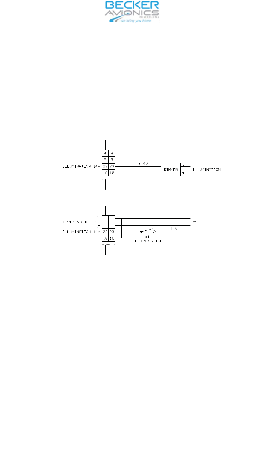
2.4.6 Pa nel lighting
The VHF trans cei ver is fit ted with pa nel lighting. It is to be con nec ted to the air craft ex ter nal po wer
supp ly via the air craft wi ring.
For 0…14 V dim ming vol ta ge ran ge con nect ILL_HI (pin 23) to dim ming vol ta ge bus and ILL_LO (pin
10) to sys tem ground (P_SUPP_GND) (re fer to the fol lo wing il lu stra ti on).
CAU TI ON :
The lighting is not swit ched off when the unit is swit ched off (ON/OFF switch)
Fig. 2-1 In ter wi ring pa nel lighting
For 0…28 V dim ming vol ta ge ran ge con nect ILL_LO (pin 10) to dim ming vol ta ge bus and ILL_HI (pin
23) to sys tem ground (P_SUPP_GND).
2.4.7 “Au xi lia ry” au dio in put
The AF-AUX (P1/4) au xi lia ry au dio in put en ab les the mo ni to ring of au dio sig nals from ot her equip ment
in the air craft. These au dio sig nals are mo ni to red in the re cep ti on mode only. The fa ci li ty to switch two
units to get her will be used par ti cu lar ly in tho
se air craft which are fit ted with a Trans cei ver and a NAV re -
cei ver. An au dio in put vol ta ge of 1 to 8 V, 600 Ohm is ne ces sa ry for mo du la ti on of the au dio am pli fier
(can be ad jus ted in the “Ser vi ce” mode).
AF AUX Pin 4 Au xi lia ry au dio in put
GND Pin 21 Au xi lia ry au dio ground
AR6201
Page 2-4 DV 14300.03/04 Issue 1 05/10
13
13
12
12
2.4.8 LINE out put
The trans cei ver has an asym me tric AF bro ad band Out put (AC cou pled). The RX AF-sig nal from the
trans cei er is pre sent at this out put. The out put le vel = 1 VRMS ± 0.2 V 1k Ohm.
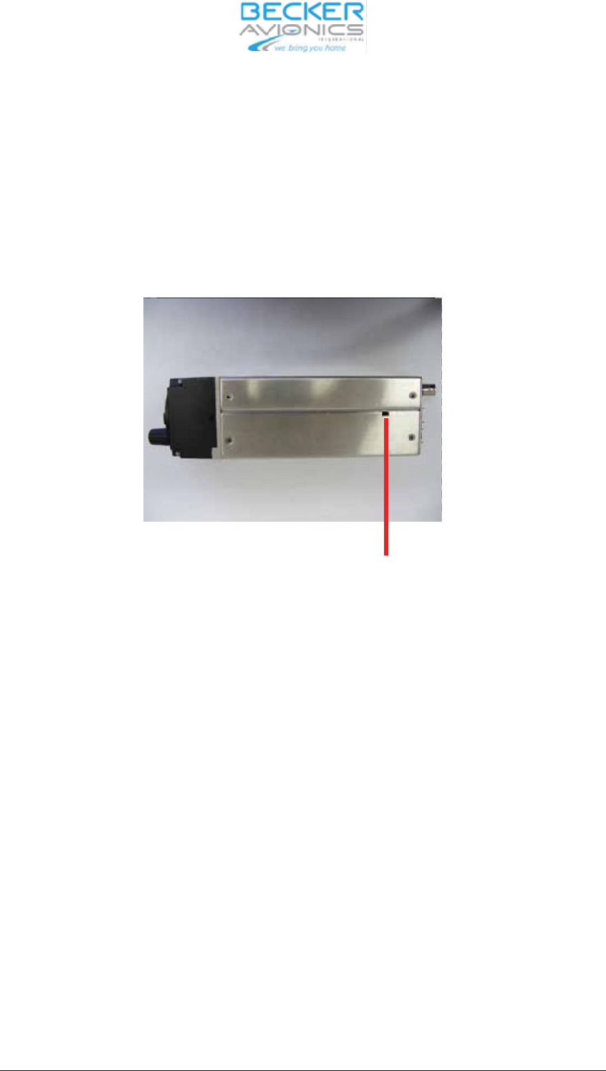
2.4.9 Lo ca tion of in ter nal au to ma tic fuse (re se ta ble)
The in ter nal au to ma tic fuse is re ac ti vat ed by me ans of a mat ching pla stic tool (self made).
Fig. 2-2 Lo ca tion of in ter nal au to ma tic fuse (re se ta ble)
AR6201
DV 14300.03/04 Issue 1 05/10 Page 2-5
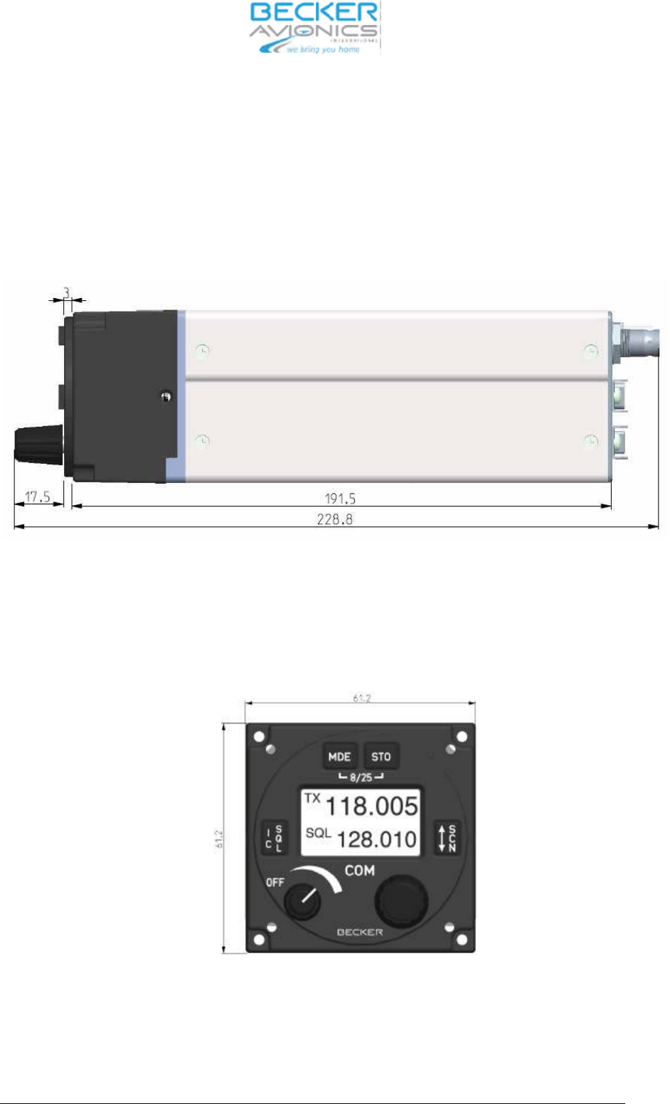
2.5 Di men sions VHF trans cei ver
Fig. 2-3 Moun ting di men sions VHF trans cei ver
AR6201
Page 2-6 DV 14300.03/04 Issue 1 05/10
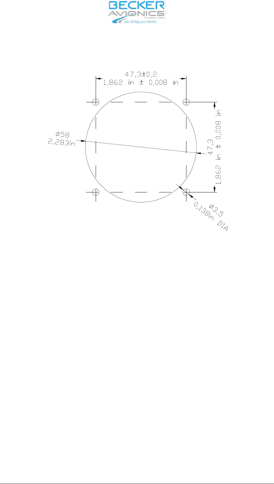
2.5.1 Dril ling jig for back-pa nel moun ting
Fig. 2-4 Dril ling jig for back-pa nel moun ting
2.6 Elec tri cal In ter fa ce Over view
•po wer supp ly
•an ten na
•he adpho ne(s)
•mi cro pho ne(s)
•PTT key.
De pen ding on the trans cei ver con fi gu ra ti on and the air craft in stal la ti on.
•ex ter nal ex chan ge key
•mi cro pho ne type switch
•squelch mo ni tor
•spea ker
•ex ter nal po wer on switch
•po wer supp ly mo ni tor out put
•au xi lia ry au dio sour ce
•In ter com key
•con trol pa nel bright ness con trol.
AR6201
DV 14300.03/04 Issue 1 05/10 Page 2-7

2.7 P1 Con nec tor (Sy stem In ter fa ces)
The P1 con nec tor is a D-SUB male con nec tor with 25 pins and sli de-in fas te ner.
Pin No. Pin Name Di rec ti on Functi on
1 SPK_HI OUT Spea ker out put sig nal
2 HDPH_A OUT Sym me tri cal Out put for He -
adpho ne(s)
3 HDPH_B OUT Sym me tri cal Out put for He -
adpho ne(s)
4 AF_AUX_IN_HI IN Au xi lia ry au dio in put
5 MIKE_DYN_HI IN Sym me tri cal in put for dy na-
mic mi cro pho ne(s)
6 MIKE_DYN_LO IN Sym me tri cal in put for dy na-
mic mi cro pho ne(s)
7 IC IN In ter com key in put;
AC TI VE sta te - clo sed con -
tact to GND
8 MIKE_STD_LO - Std. Mic. Low (re turn)
9 NC not connected
10 ILL_LO IN Il lu mi na ti on low in put
11 P_SUPP IN Po wer supp ly Hot (po si ti ve)
12 P_SUPP IN Po wer supp ly Hot (po si ti ve)
13 P_SUPP_GND - Po wer supp ly Ground (re -
turn)
14 SPK_LO - Spea ker ground (re turn)
15 LINE_OUT OUT Au xi lia ry au dio out put
16 AGC_OUT OUT Re cei
ver AGC out put
17 /PTT IN Press To Talk key in put
AC TI VE sta te - clo sed con -
tact to GND
18 MIKE_STD_HI IN Std. Mic. High
19 CPIN IN Co ding PIN
20 NC - not con nec ted
21 AF_AUX_IN_LO - Au xi lia ry au dio in put ground
22 NC - -
23 ILL_HI IN Il lu mi na ti on high
24 /PWR_EVAL - Po wer on Mo ni tor out put
25 P_SUPP_GND - Po wer supp ly Ground (re -
turn)
AR6201
Page 2-8 DV 14300.03/04 Issue 1 05/10

2.8 J1 Con nec tor (Se ri al In ter fa ces and Di scre te I/Os)
The J1 con nec tor is a D_SUB fe ma le con nec tor with 25 pins and sli de-in fas tener.
Pin No. AR6201 Pin Name Di rec ti on Functi on
1 CPIN - Co ding PIN
2 TX2+ IN In ter fa ce 2 OUT+
3 RX2+ IN In ter fa ce 2 IN+
4 /SQL_EVAL out squelch mo ni tor out put
AC TI VE sta te - clo sed con tact to GND
5 /CSDB_EXT IN Ex ten ded CSDB pro to col en ab ling
AC TI VE sta te - clo sed con tact to GND
6 SHIELD_1 - In ter fa ce 1 SHIELD
7 TX1+ OUT In ter fa ce 1 OUT+
8 RX1+ IN In ter fa ce 1 IN+
9 TX2- OUT In ter fa ce 2 OUT-
10 RX2- IN In ter fa ce 2 IN-
11 SHIELD_2 - In ter fa ce 2 SHIELD
12 /EXT_SO IN Ex ter nal ”Ex chan ge” key
AC TI VE sta te - clo sed con tact to GND
13 /SRV_EN IN Ser vi ce en ab le pin
AC TI VE sta te - clo sed con tact to GND
14 TX1- OUT In ter fa ce 1 OUT-
15 RX1- IN In ter fa ce 1 IN-
16 NC not con nec ted
17 NC not con nec ted
18 NC not con nec
ted
19 NC not con nec ted
20 (/GPI) IN Ge ne ral Pur po se In put pin (un used, for fu tu-
re pur po ses)
AC TI VE sta te - clo sed con tact to GND
21 D_GND - Di scre te li nes ground
22 D_GND - Di scre te li nes ground
23 D_GND - Di scre te li nes ground
24 /MIKE_SW IN Mi cro pho ne type se lec tor in put
AC TI VE sta te - clo sed con tact to GND
25 /ON IN Ex ter nal Po wer ON in put
AC TI VE sta te - clo sed con tact to GND
AR6201
DV 14300.03/04 Issue 1 05/10 Page 2-9
2.9 An ten na con nec tor
Bayo net Nut Con nec tor (BNC 50 Ohm).
2.10 Trans cei ver groun ding
The trans cei ver in clu des a groun ding bolt (M4 thre aded bolt).
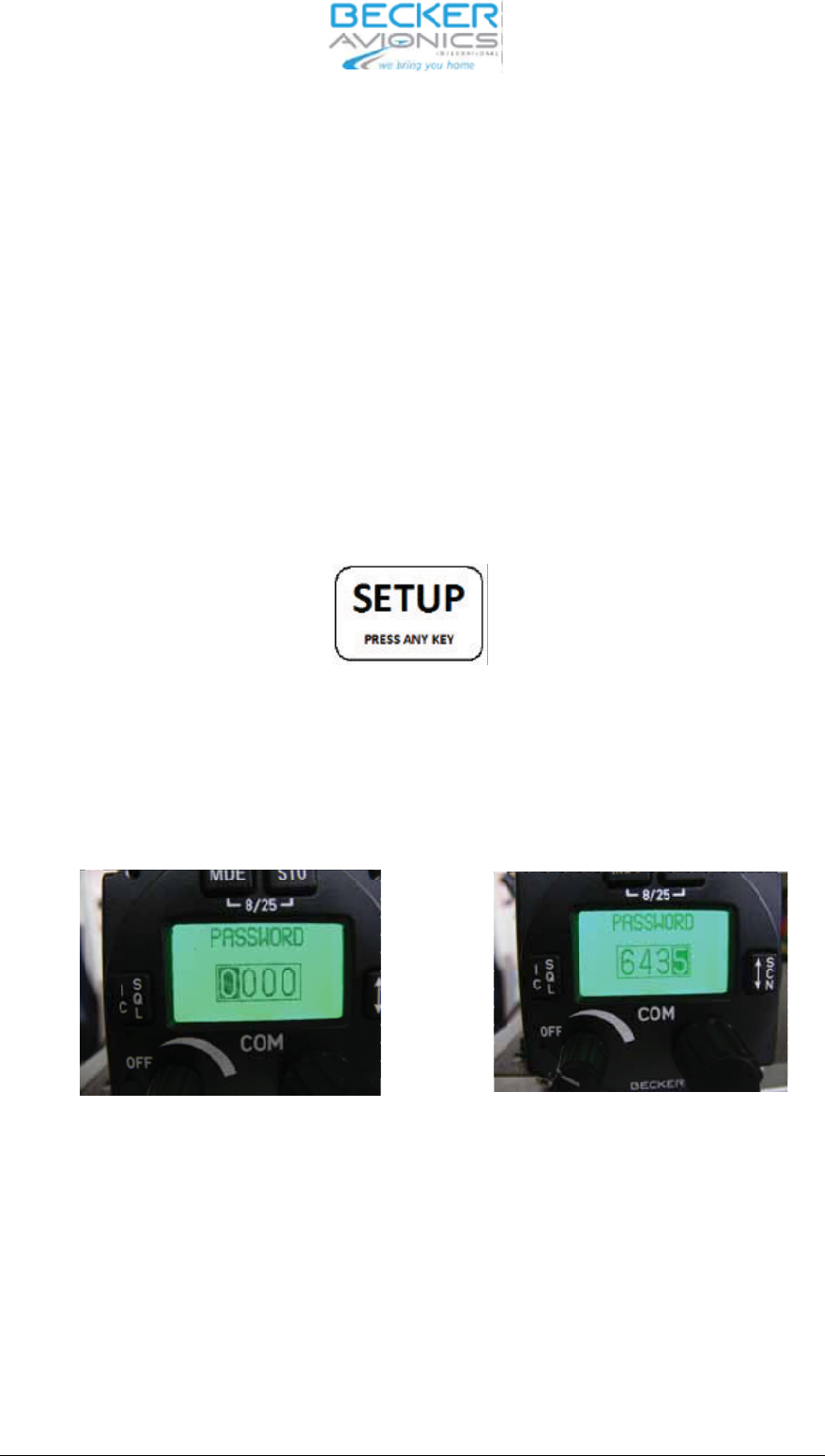
2.11 Ser vi ce mode
The ser vi ce mode is me ant to en ab le the ground tech ni ci ans to set the equip ment con fi gura ti on and
must not be used in flight. The ser vi ce mode is ac ti vat ed when the MDE key is pres sed whi le the trans -
cei ver is swit ched ON.
”SE TUP” is in di ca ted on the screen, press any key en ter the ser vi ce mode.
Se tup in di ca tion
Set the 4-digit nu me ri cal code pass word “6435” using ”ro ta ry en co der” and push but ton of the ”ro ta-
ry en co der” and con firm by pus hing the ”STO” but ton.
Pass word Dia log
AR6201
Page 2-10 DV 14300.03/04 Issue 1 05/10
Push ”ro ta ry en co-
der”
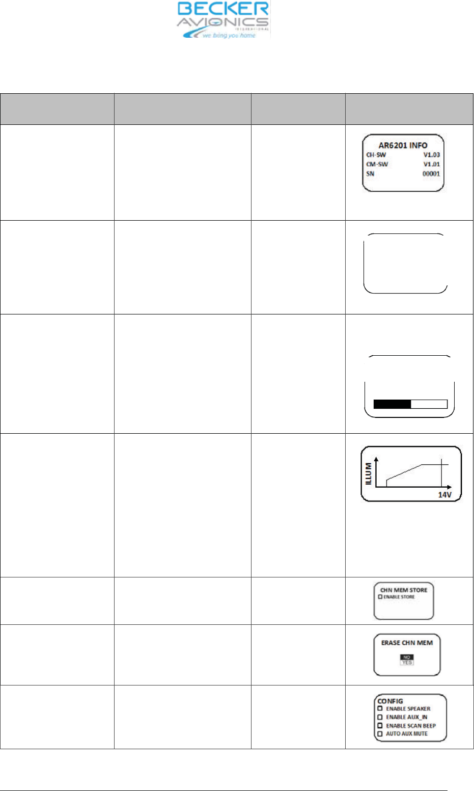
Turn ”ro ta ry en co der” Ope ra ting View and Con di tions
AR6201 INFO CH-SW
(Con trol Head CH)
CM-SW
(chas sis mo du le CM)
SN
(Se ri al Num ber)
View only
Dim ming input None
0 - 14 V DC
0 - 28 V DC
Push STO key will
ac ti va te the se lec-
ted op ti on
BRIGHT NESS 0%...50%...100% Ad just ment is sto-
red au to ma ti cal ly
wit hout pus hing
STO key
Dis play ed only if Dim ming in put
is set to ”NONE”
IL LUM CUR VE Cha rac te ris tic points:
A - Mi ni mum Il lu mi na ti on
B – Ma xi mum Il lu mi na ti on)
Y - Mi ni mum Dim ming Vol ta-
ge
Z - Ma xi mum Dim ming Vol ta-
ge
Ad just ment is sto-
red au to ma ti cal ly
wit hout pus hing
STO key
Dis play ed only if Dim ming in put
dif fe rent than ”NONE”
14V or 28V is dis play ed de pen-
ding on se lec ti on
EN AB LE STO RE En ab le Sto re Pus hing STO key
ac ti va tes the se -
lec ted op ti on
ERA SE_MEM
(Era se me mo ry chan -
nels for se lec ted chan -
nel spa cing only)
NO
YES
Pus hing STO key
ac ti va tes the se -
lec ted op ti on
CON FIG En ab le Spea ker
En ab le AF_AUX_IN
En ab le SCAN BEEP
Au to ma tic AUX mute
Pus hing STO key
is tog gle ON/OFF
the se lec ted va ria-
ble
AR6201
DV 14300.03/04 Issue 1 05/10 Page 2-11
BRIGHTNESS
50%
DIMMING IN
ONONE
?0-14V
O0-28V
Push ”ro ta ry en co-
der”
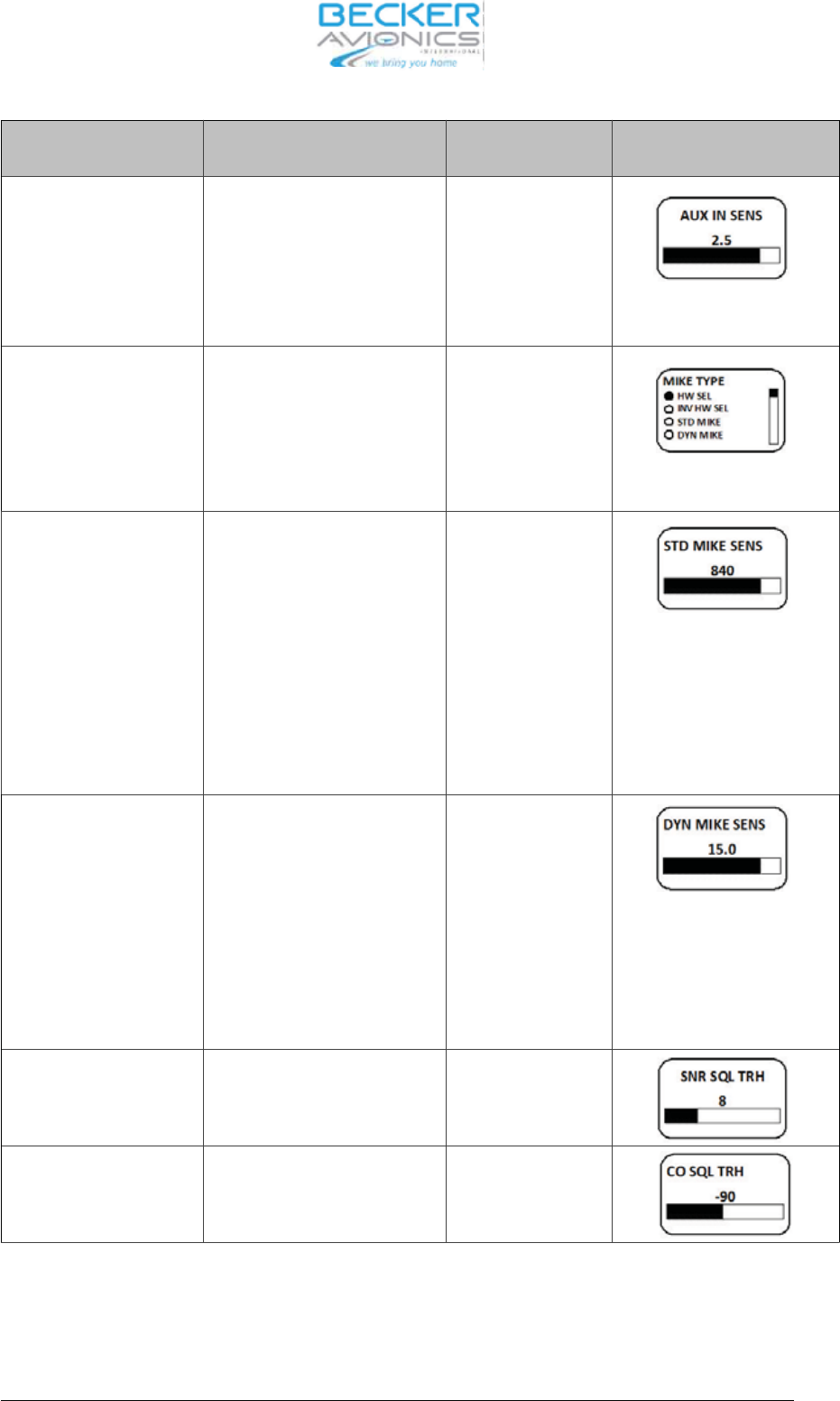
Turn ”ro ta ry en co der” Ope ra ting View and Con di tions
AF_AUX_IN SEN SI TI-
VI TY
1.0..8.0V,
step 0.1V
Ad just ment is sto -
red au to ma ti cal ly
wit hout pus hing
STO key
Dis play ed only if
AF_AUX_IN En ab led
MIKE TYPE HARD WA RE SE LEC TI ON
IN VER TED HARD WA RE
SE LEC TI ON
STD MIKE
DYN MIKE
MI XED
Ad just ment is sto -
red au to ma ti cal ly
wit hout pus hing
STO key
STD MIKE SEN SI TI VI-
TY
10..1000 mV, in 10 mV steps Ad just ment is sto -
red au to ma ti cal ly
wit hout pus hing
STO key
Dis play ed if MI XED or
STD_MIKE Type is cho -
sen by soft
wa re or Mike
Type is set to hard wa re
se lec ti on and STD_MIKE
is se lec ted on ex ter nal pin
DYN MIKE SEN SI TI VI-
TY
1.0..20.0 mV
in 0.2 mV step
Ad just ment is sto -
red au to ma ti cal ly
wit hout pus hing
STO key
Dis play ed if MI XED or
DYN_MIKE Type is cho sen by
soft wa re or Mike Type is set to
hard wa re se lec ti on and DYN
Mike is se lec ted on ex ter nal pin
SNR SQUELCH
THRES HOLD
6 ... 12 dB Ad just ment is sto-
red au to ma ti cal ly
wit hout pus hing
STO key
CO SQUELCH
THRES HOLD
-95 ... -85 dBm Ad just ment is sto-
red au to ma ti cal ly
wit hout pus hing
STO key
Page 2-12 DV 14300.03/04 Issue 1 05/10
AR6201
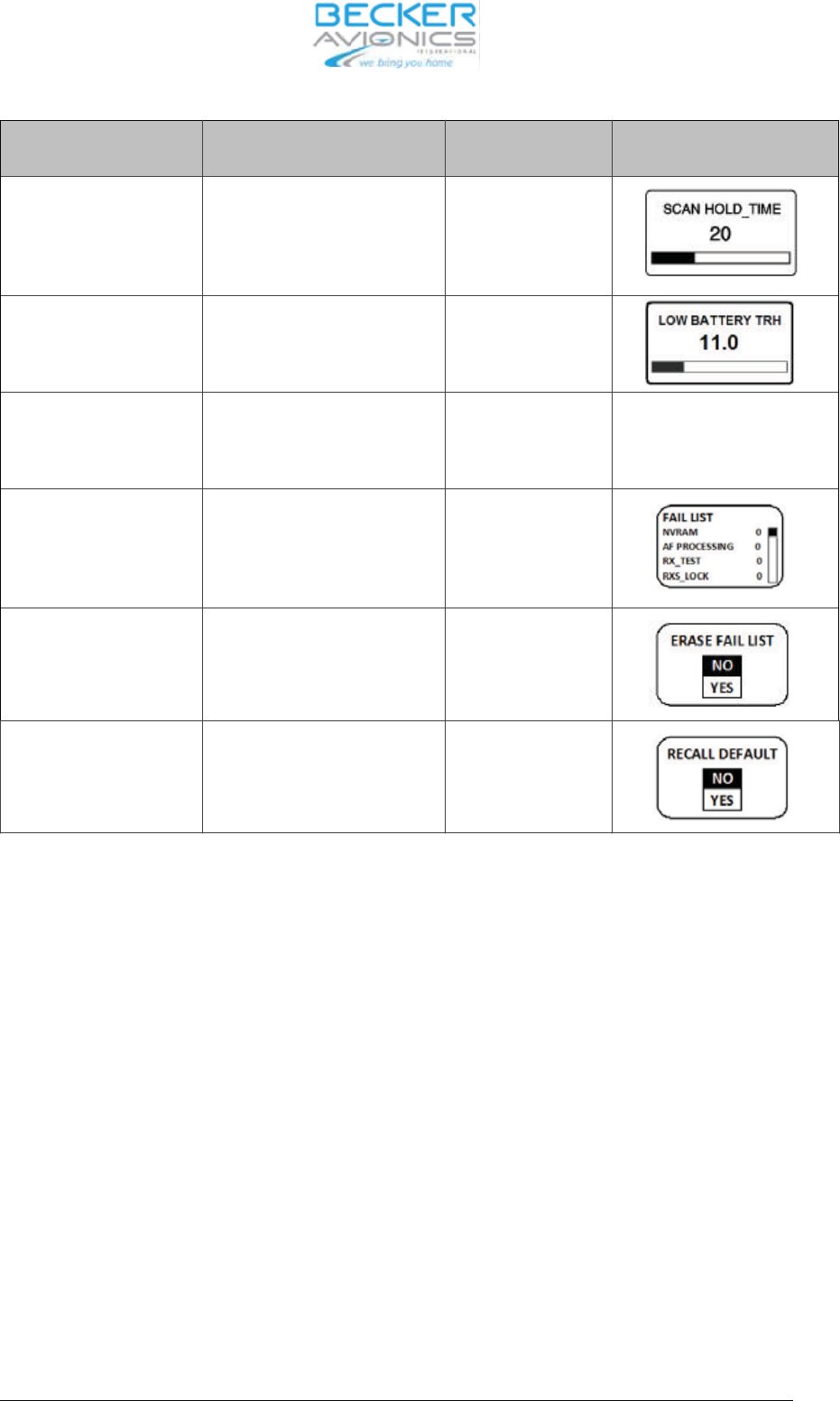
Push ”ro ta ry en co-
der”
Turn ”ro ta ry en co der” Ope ra ting View and Con di tions
SCAN HOLD TIME 1..60 s Ad just ment is sto-
red au to ma ti cal ly
wit hout pus hing
STO key
LOW BAT TE RY
THRES HOLD
10.0 ... 33.0 V, step 0.1 V Ad just ment is sto-
red au to ma ti cal ly
wit hout pus hing
STO key
SI DE TO NE ATT 0…12dB Ad just ment is sto-
red au to ma ti cal ly
wit hout pus hing
STO key
AR ER ROR LATCH PBIT and CBIT Fai lu re List
ac cor ding /BIT/
View only
ERA SE FAIL LIST
(LAT CHES)
NO
YES
Pus hing STO key
ac ti va tes the se -
lec ted op ti on
RE CALL DE FAULT
(FAC TO RY)
NO
YES
Pus hing STO key
ac ti va tes the se -
lec ted op ti on
To re turn from ser vi ce mode the de vi ce must be tur ned OFF and ON again.
AR6201
DV 14300.03/04 Issue 1 05/10 Page 2-13
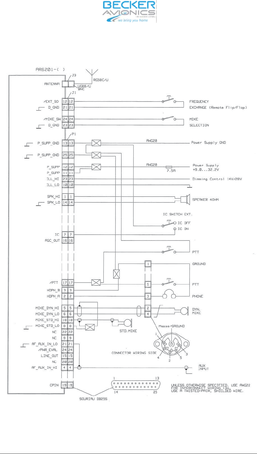
2.12 In ter wi ring dia gram of the VHF trans cei ver
Fig. 2-5 In ter wi ring of the VHF trans cei ver
AR6201
Page 2-14 DV 14300.03/04 Issue 1 05/10
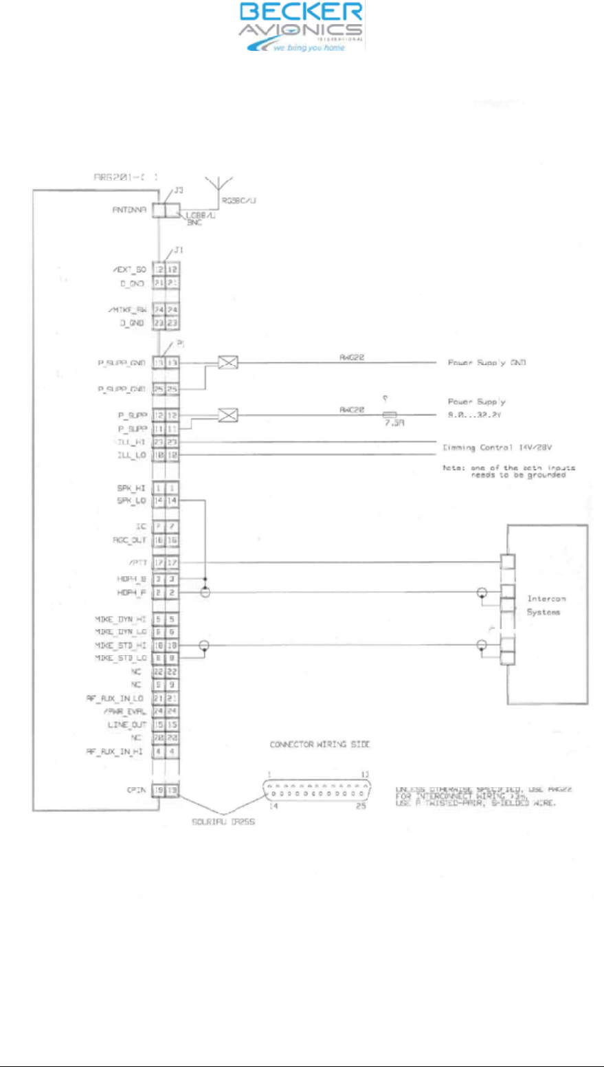
Fig. 2-6 In ter wi ring dia gram VHF trans cei ver with in ter com sy stems
AR6201
DV 14300.03/04 Issue 1 05/10 Page 2-15
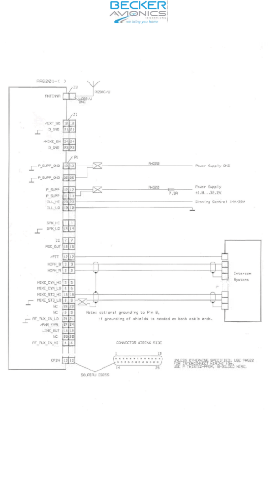
Fig. 2-7 In ter wi ring dia gram VHF trans cei ver with in ter com sy stems
AR6201
Page 2-16 DV 14300.03/04 Issue 1 05/10

2.13 Te sting af ter in stal la ti on
2.13.1 Ground test with en gi ne shut down.
Af ter in stal la ti on of the unit, mea su re the an ten na tu ning bet ween the base of the an ten na and the an -
ten na con nec ting ca ble using a VHF re flec ti on-co ef fi cient me ter (vol ta ge stan ding wave me ter).
The VSWR (vol ta ge stan ding wave ra tio) over the com ple te fre quen cy ran ge of the unit shall be wit hin
3:1. If this mat ching va lue is ex cee ded it in di ca tes a mis match, cau sed for ex am ple by an in cor rect or
unsatis fac to ry coun ter poi se, a ca ble with an im pe dan ce which de via tes sig ni fi cant ly from 50 Ohm or
an in cor rect ly tu ned an ten na, or faults on the BNC con nec tors of the an ten na cable.
2.13.2 Ground test with en gi ne run ning.
With the en
gi ne run ning at crui sing speed check that the air craft po wer supp ly is wit hin the per mis si ble
to le ran ces at ap pro xi ma te ly 14 V.
When per for ming a com mu ni ca tion test, en su re that the dis tan ce from the ground sta ti on is as great as
pos si ble, at least 100 m. With the en gi ne at crui sing speed, the ca bin noi se of the air craft should be
only slight ly trans mit ted and com mu ni ca ti on should be cle ar and dis tinct. Hold the mi cro pho ne clo se to
the lips whi le spea king.
Ac ti va te the in ter com function and car ry out a speech test with the en gi ne run ning at crui sing speed. If
ne ces sa ry, ad just the IC vo lu me (re fer to the ser vi ce mode).
Switch on the squelch and check the squelch functi on. The thres hold of the squelch can be set in the
ser vi ce mode .
The si de to ne vo lu me can be adap ted to pi lots con ve nien ce. If ne ces sa ry, ad
just the si de to ne vo lu me
(re fer to the ser vi ce mode). When using the loud spea ker, the si de to ne should be ad ju sted to zero, so
that no acous tic feed back oc curs.
AR6201
DV 14300.03/04 Issue 1 05/10 Page 2-17

Blank
AR6201
Page 2-18 DV 14300.03/04 Issue 1 05/10

Tab le of con tents
Sec tion 3 Ope ra tion Page
3.1 Con trols and in di ca tors 3-1
3.1.1 Rear of unit 3-4
3.1.2 Ope ra ting in struc tions 3-5
3.1.3 Ge ne ral but ton functio nal des crip tion 3-5
3.1.4 Start–up 3-5
3.1.5 Mode se lec tion 3-5
3.2 Mode se lec tion function 3-6
3.2.1 Mode tran si tion ru les: 3-6
3.2.2 Stan dard mode. 3-6
3.2.3 Scan Sub-mode 3-6
3.3 Fre quen cy se lec tion function 3-7
3.3.1 Di rect tune mode 3-9
3.3.2 Chan nel mode 3-9
3.4 Sto ra ge function 3-10
3.4.1 Au to ma tic sto ra ge function. 3-10
3.5 In ter com set tings 3-11
3.5.1 In ter com vo lu me / VOX set tings 3-11
3.6 Squelch function 3-12
3.7 Chan nel spa cing swit cho ver 25 kHz 8.33 kHz 3-12
3.8 Spe ci al set ting of bright ness and squelch thres hold 3-13
3.9 Built-In Test 3-14
3.9.1 CBIT test re sults in di ca tion 3-14
3.9.2 CBIT Stuck_PTT war ning 3-14
3.9.3 CBIT TX_HOT war ning pre sen ta tion mode 3-14
3.9.4 CBIT LOW BAT TE RY war ning pre
sen ta tion mode 3-14
3.9.5 CBIT TX_HOT, Stuck_PTT and LOW BAT TE RY war nings 3-15
3.9.6 CBIT fai lu re 3-15
3.10 Sa fe ty in struc tions 3-16
3.11 RF Ex po su re In for ma tion 3-16
Fig. 3-1 Con trols and in di ca tors 3-1
Fig. 3-2 Rear side 3-4
AR6201
DV 14300.03/.04 Is sue 1 05/10 Page 3-I

Blank
AR6201
Page 3-II DV 14300.03/.04 Is sue 1 05/10
Sec tion III OPE RA TION
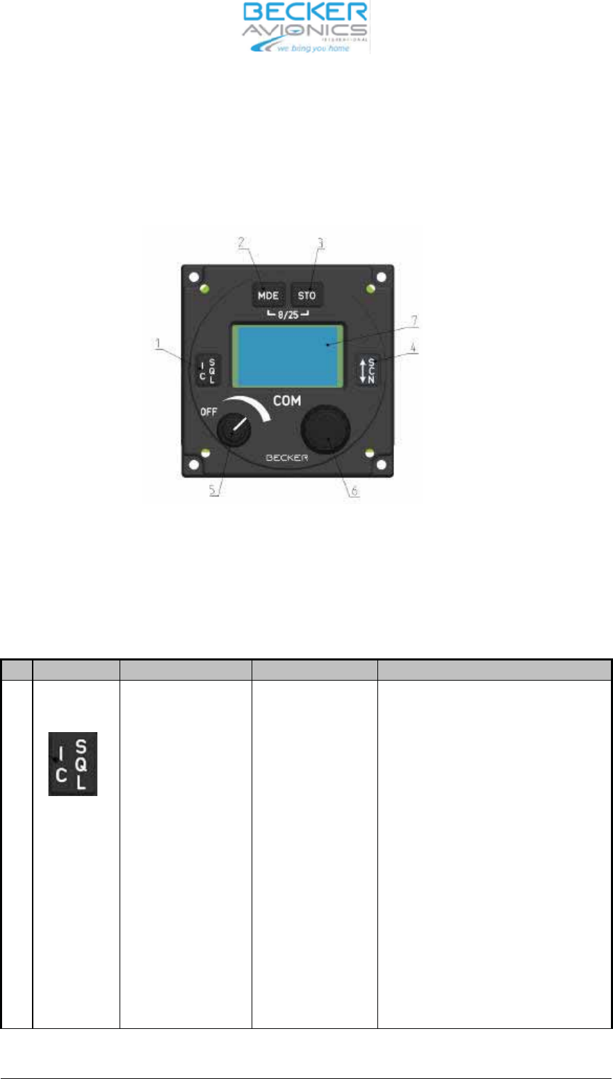
3.1 Con trols and in di ca tors
Fig. 3-1 con trols and in di ca tors
Mea ning of sym bols on con trols and in di ca tors
Sym bol Des crip ti on Type Des crip ti on
1.Squelch/IC key Push but ton ”Short press” du ring nor mal ope ra ti on
tog gles squelch ON/OFF sta te.
“Short press” du ring In ter com set tings
tog gles bet ween IC Vo lu me set tings
and VOX set tings.
“Short press” du ring Se tup mo ves
menu in back ward di rec ti on.
“Long press” du ring nor mal ope ra ti on
ac ti va tes IC vo lu me set ting.
”Long press” du ring VOX set ting de -
ac ti va tes VOX set ting and re turns to
pre vi ous se lec ti on mode
AR6201
DV 14300.03/04 Issue 05/10 Page 3-1
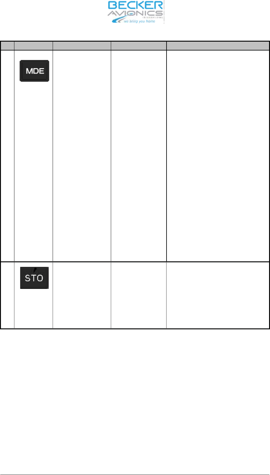
Sym bol Des crip ti on Type Des crip ti on
2 Mode key Push but ton “Short press” du ring nor mal ope ra ti on
chan ges se lec ti on mo des.
“Long press” du ring nor mal ope ra tion
ac ti vat ed the set ting for the bright -
ness and squelch thres hold .
When Key pressed du ring the trans -
cei ver is switch ON, the ser vi ce
mode is activated.
“Long press” to get her with ”STO” key
du ring nor mal ope ra ti on tog gles
8.33+25 kHz and 25 kHz chan nel
spa cing.
“Short press” du ring In ter com set tings
re turns to pre vi ous se lec ti on mode.
Short press” du ring Scan Sub-mode
lea ves Scan Sub-mode to Stan dard
mode.
3 Sto re key Push but ton ”Short press” du ring nor mal ope ra ti on
ac ti va tes sto ra ge pro ce du re.
“Long press” to get her with MDE key
du ring nor mal ope ra ti on tog gles
8.33+25 kHz and 25 kHz chan nel
spa cing.
AR6201
Page 3-2 DV 14300.03/04 Issue 05/10
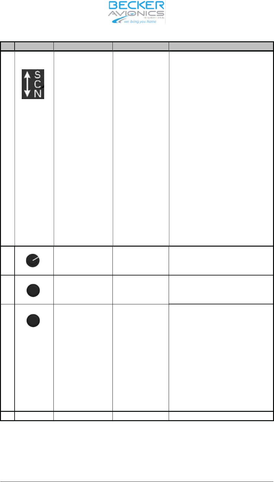
Sym bol Des crip ti on Type Des crip ti on
4.Ex chan ge/SCAN key Push but ton ”Short press” du ring ”Stan dard mode”
and Scan Sub mode ex chan ges pre -
set fre quen cy and ac ti ve fre quen cy.
“Short press” du ring Se tup mo ves
menu in for ward di rec ti on.
“Long press” in Stan dard mode, Di -
rect mode and Chan nel mode ac ti va-
tes Scan Sub-mode.
“Short press” du ring Scan Sub-mode
ex chan ges pre set fre quen cy and ac ti-
ve fre quen cy wit hout lea ving the
Scan Sub-Mode.
“Long press” du ring Scan Sub-mode
lea ves Scan Sub-mode wit hout ex -
chan ging pre set and ac ti ve fre quen-
cy.
5 ON/OFF po wer
switch with vo lu me
po ten tio me ter
Vo lu me po ten tio me-
ter com bi ned with
po wer switch
Swit ches po wer ON/OFF and ad justs
vo lu me le vel.
6a Ro ta ry en co der Op ti cal en co der
(with in te gra ted
push but ton)
16 steps per turn ro ta ry en co der,
used to chan ge set tings.
6b Push but ton of the
ro ta ry en co der
Push but ton (of the
op ti cal en co der)
Push but ton to move bet ween di gits
for set tings, ac cep tan ce of se lec tions;
ge ne ral ly trea ted as an en ter key.
“Short press” du ring Scan Sub-mode
ac ti va tes set ting of pre set fre quen cy
(see fre quen cy se lec ti on functi on for
de tails)”.
Short press” du ring IC vo lu me set -
tings ac ti va tes VOX set tings.
7 LCD dis play Dot ma trix Li quid crys tal dis play
AR6201
DV 14300.03/04 Issue 05/10 Page 3-3
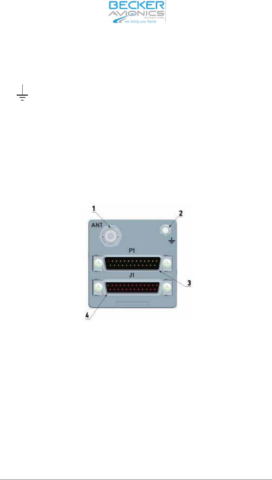
3.1.1 Rear of unit
1 ANT BNC 50 Ohm an ten na con nec tor.
2 Groun ding bolt
3 P1 25-pin D sub-male Equip ment con nec tor for con nec ting
the in stal la tion wi ring.
4 J1 25-pin D sub-female Equip ment con nec tor for con nec ting
the in stal la tion wi ring.
Fig. 3-2 Rear side
AR6201
Page 3-4 DV 14300.03/04 Issue 05/10

3.1.2 Ope ra ting in struc tions
3.1.3 Gen eral but ton functio na li ty des crip ti on
When any push but ton is pres sed, and the ope ra ti on per for med by this con trol is not al lo wed at this
time, then for a short pe ri od of time who le con tent of the dis play is in ver ted.
Long press is de tec ted when the user presses and holds the key for at least 3 se conds, ot her wi se
Short press is as su med.
3.1.4 Start–up
CAU TION
Do not switch ON the VHF trans cei ver when en gi nes are being start ed or shut down.
Note:
Ex ces si ve pul ses on the DC Bus of the air craft may cau se a da ma ge on elec tri cal cir cuits of any in -
stal led in stru ment
a. Switch ON the VHF trans cei ver using the ON/OFF po wer switch.
Du ring PBIT, dis play is first swit ched to black for 1 se cond to get her with set ting Il lu mina tion to 100%
and then swit ched to whi te for 1 se cond (dis play test) to get her with set ting Il lu mi na tion to 0% and
slowly (1 … 5 se conds) in crea sing Il
lu mi na tion to the last sa ved va lue.
b. Af ter PBIT the dis play in di ca tes the mes sa ge ”WAIT” the soft wa re ver sion of “Con trol Head” (CH)
and the soft wa re ver sion of “Chas sis Mo du le” (CM) are in di ca ted.
c. If the PBIT has de tec ted er ror(s), the dis play in di ca tes ”FAI LU RE” (for de tails see chap ter 3.9.6)
3.1.5 Mode se lec ti on
The re are three se lec ti on mo des:
Stan dard mode
Di rect tune mode
Chan nel mode
DV 14300.03/04 Issue 05/10 Page 3-5
AR6201
3.2 Mode se lec ti on functi on
When the MDE key is short ly pres sed, the se lec ti on mode chan ges from Stan dard mode to Di rect
tune mode or Chan nel mode.
3.2.1 Mode tran si ti on ru les
When chan ged from Stan dard mode to Di rect tune mode the ac ti ve fre quen cy stays the same.
When chan ged from Di rect tune mode to Chan nel mode the ac ti ve fre quen cy stays the same. If the
ac ti ve fre quen cy has no as sig ned chan nel num ber this is in di ca ted in the dis play as ”CH —”
When swit ching from Chan nel mode to Stan dard mode the ac ti ve fre quen cy stays the same and
the pre set fre quen cy stays the same as be fo re lea ving Stan dard mode.
3.2.2 Stan dard mode
Both pre set and ac ti ve fre quen cies are in di ca ted on Dis play. The ac ti ve fre quen cy is in di ca ted in
the top line. The pre set fre quen cy is in di ca ted in the bot tom line. The pre set fre quen cy is set
tab le
by using the ”Ro ta ry en co der” (see fre quen cy se lec ti on functi on).
Short press the ”Ex chan ge/SCAN” key to ex chan ge ac ti ve and pre set fre quen cy. Ex chan ge is dis -
ab led whi le the trans cei ver is in trans mit mode.
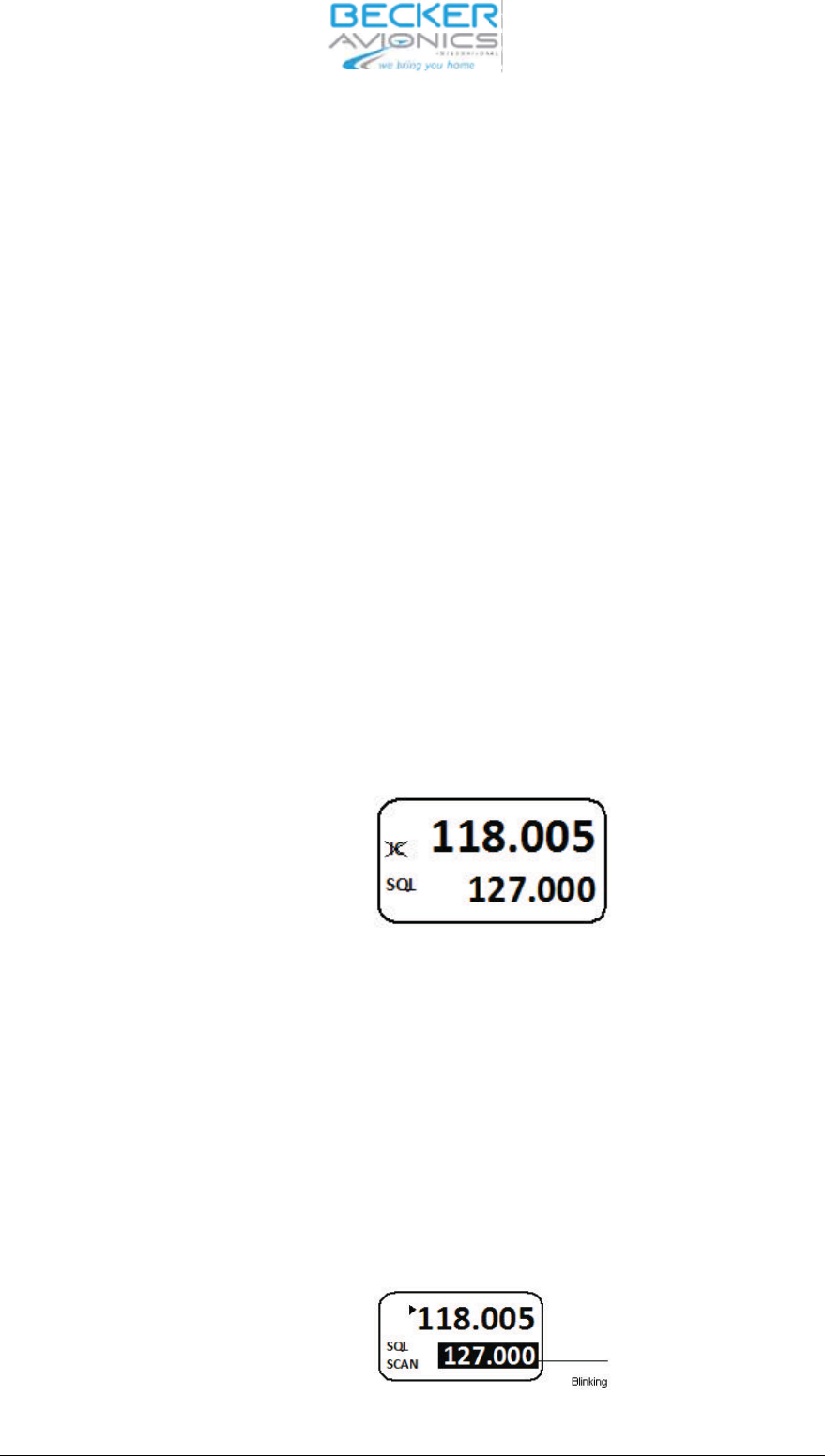
3.2.3 Scan Sub-mode
The Scan Sub-mode can be ac ti vat ed by a long press of Ex chan ge/SCAN key in all se lec ti on mo -
des
Note: Lea ving Scan Sub-mode me ans going back to the Stan dard mode
A short press off the MDE key chan ges back from Scan Sub-mode to Stan dard mode.
Both pre set and ac ti ve fre quen cies are in di ca ted on dis play. The ac ti ve fre quen cy is in di ca ted in
the top line. The pre set fre quen cy is in di ca ted in the bot tom line.
The SCAN sign in the dis play in di ca tes scan ning mode is ac ti ve.
Page 3-6 DV 14300.03/04 Issue 05/10
AR6201
If sig nal is de tec ted on the ac ti ve fre quen cy and also si gnal is de tec ted on the pre set fre quen cy
(car rier de tec ted), the pre set fre quen cy is in ver ted.
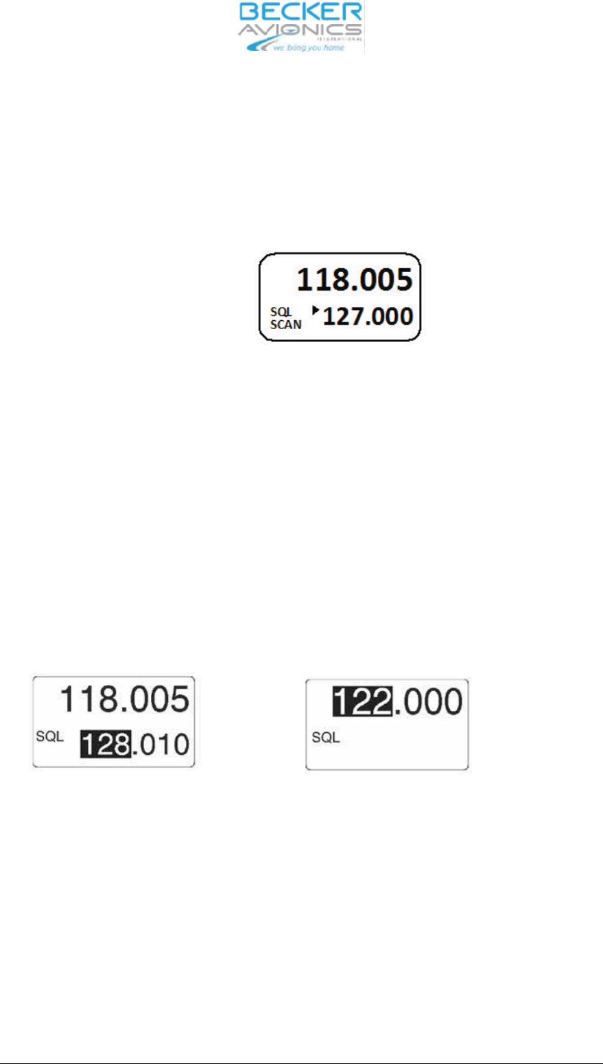
A arrow sign near ac ti ve fre quen cy in di ca tes that ac ti ve fre quen cy au dio is pro vi ded to the au dio
out puts.
If a sig nal is de tec ted on pre set fre quen cy, whi le not hing on the ac ti ve fre quen cy is received, an ar -
row sign near pre set fre quen cy in di ca tes that pre set fre quen cy au dio is pro vi ded to the au dio out -
puts.
Short press of the Ex chan ge/SCAN key ex chan ges pre set fre quen cy and ac ti ve fre quen cy wit -
hout lea ving scan sub-mode. Ex chan ge is dis ab le whi le the trans cei ver is in trans mitt mode.
Long press of the Ex chan ge/SCAN key lea
ves scan sub-mode (wit hout ex chan ging pre set and ac -
ti ve fre quen cy to Stan dard mode).
Short press of the en co der push but ton ac ti va tes set ting of pre set fre quen cy (see fre quen cy se lec-
ti on functi on for de tails).
3.3 Fre quen cy se lec ti on functi on
Note:
Left side fi gu re for Stan dard mode, right side fi gu re for Di rect tune mode
Fre quen cy MHz se lec ti on
If se lec ted chan nel spa cing is 25+8.33 kHz (mi xed mode), the fre quen cy is dis play ed in 6 di gits,
three for MHz and three for kHz. If se lec ted spa cing is 25 kHz, fre quen cy is dis play ed in 5 di gits,
three for MHz and two for kHz.
Di rect edi ting of the ac ti ve fre quen cy whi le trans mit ter is in trans mit mode is disabled.
DV 14300.03/04 Issue 05/10 Page 3-7
AR6201
Fre quen cy se lec tion
By a short press of the Ro ta ry en co der Push but ton the MHz di gits are in ver ted. By tur ning Ro ta-
ry en co der the MHz fre quen cy is in cre men ted/de cre men ted in 1 MHz steps de pen ding on the tur -
ning di rec tion.
Note:
A ti me out of 5 se conds is im ple men ted to abort se lec tion mode if no user ac tion oc curs.
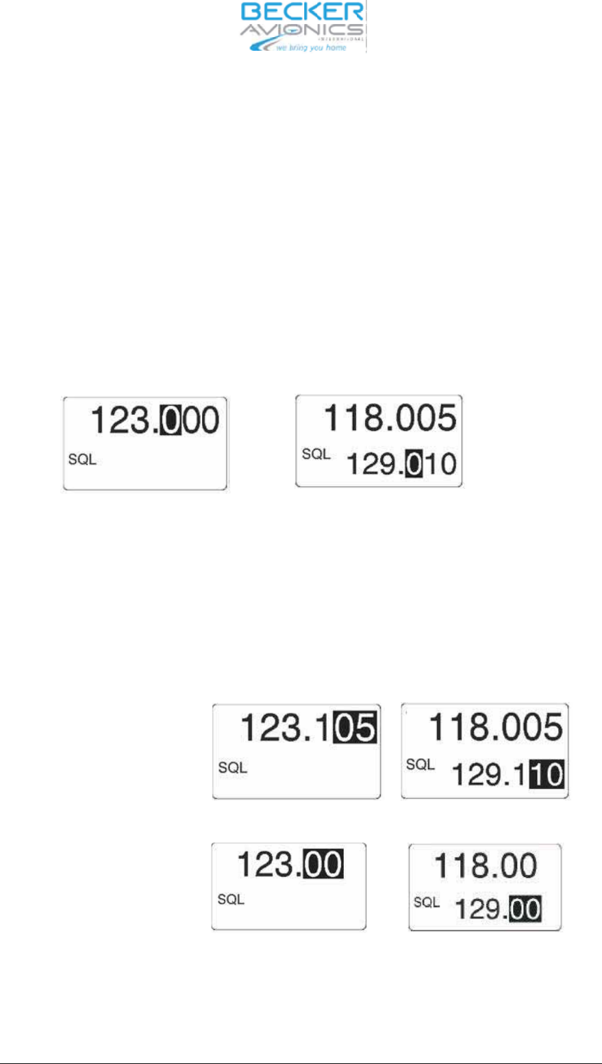
By short press of the Ro ta ry en co der Push but ton again, the 100 kHz kHz spa cing is se lec ted.
The 100 kHz di gits are in ver ted, by tur ning Ro ta ry en co der kHz-fre quen cy is in cre men ted/de cre-
men ted de pen ding on the tur ning di rec ti on in 100 kHz steps.
Note:
A ti me out of 5 se conds is im ple men ted to ab ort se lec tion mode if no user ac tion oc curs.
Fre quen cy hun
dreds di git se lec ti on
By a short press of the Ro ta ry en co der Push but ton again the tens / 25 kHz (de pen ding chan nel
spa cing 8.33 or 25 kHz mode) di gits are in ver ted and by tur ning Ro ta ry en co der the in di ca ti on is
in cre men ted/de cre men ted de pen ding on the tur ning di rec ti on.
Note:
A ti me out of 5 se conds is im ple men ted to ab ort se lec tion mode if no user ac tion oc curs.
Chan nel spa cing 8.33 kHz mode
Else
Chan nel spa cing 25 kHz mode
Fre quen cy kHz se lec tion
By short press of the Ro ta ry en co der Push but ton again, the fre quen cy se lec ti on is can cel led.
Page 3-8 DV 14300.03/04 Issue 05/10
AR6201
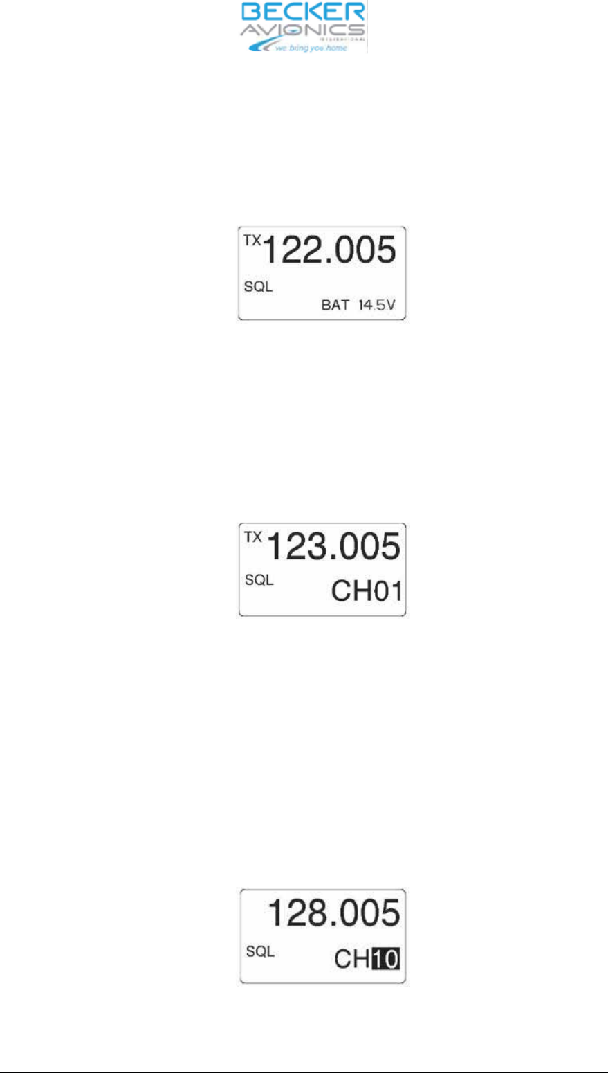
3.3.1 Di rect tune mode
The ac ti ve fre quen cy is in di ca ted in the top line.
The ac ti ve fre quen cy is set di rect ly using the Ro ta ry en co der if the trans cei ver is not in trans -
mit mode.
By fre quen cy chan ge in Di rect tune mode, the chan ges be co me ac ti ve im me di ate ly
On the bot tom line the bat te ry sign is in di ca ted with po wer vol ta ge va lue.
3.3.2 Chan nel mode
Se lect the chan nel mode by short press of the MDE key. In the top line of the dis play the sto -
red fre quen cy is in di ca ted. In the bot tom line of the dis play, the chan nel num ber is in di ca ted.
By a short press of the Ro ta ry en co der Push but ton the chan nel num ber is in ver ted.
Se lect the re qui red chan nel num ber by tur ning the Ro ta ry en co der (in cre
men ted / de cre-
men ted de pen ding on the tur ning di rec tion).
Only se lec ti on of chan nels with as sig ned fre quen cy in the se lec ted chan nel spa cing is pos si-
ble.
Note:
A ti me out of 5 se conds is im ple men ted to ab ort se lec tion mode if no user ac tion oc curs.
Exit from chan nel se lec tion is achie ved by short pres sing the Ro ta ry en co der Push but ton.
Chan nel di gits se lec ti on
DV 14300.03/04 Issue 05/10 Page 3-9
AR6201
3.4 Sto ra ge functi on
It is pos si ble to ac ti va te sto ra ge functi on in all se lec ti on mo des.
Du ring sto ra ge pro ce du re:
❐”STO” text is dis play ed on the left side of the dis play.
❐The trans cei ver is rea dy to trans mit and re cei ve on the fre quen cy as ac ti ve in pre vi-
ous mode, wit hout any re stric ti on.
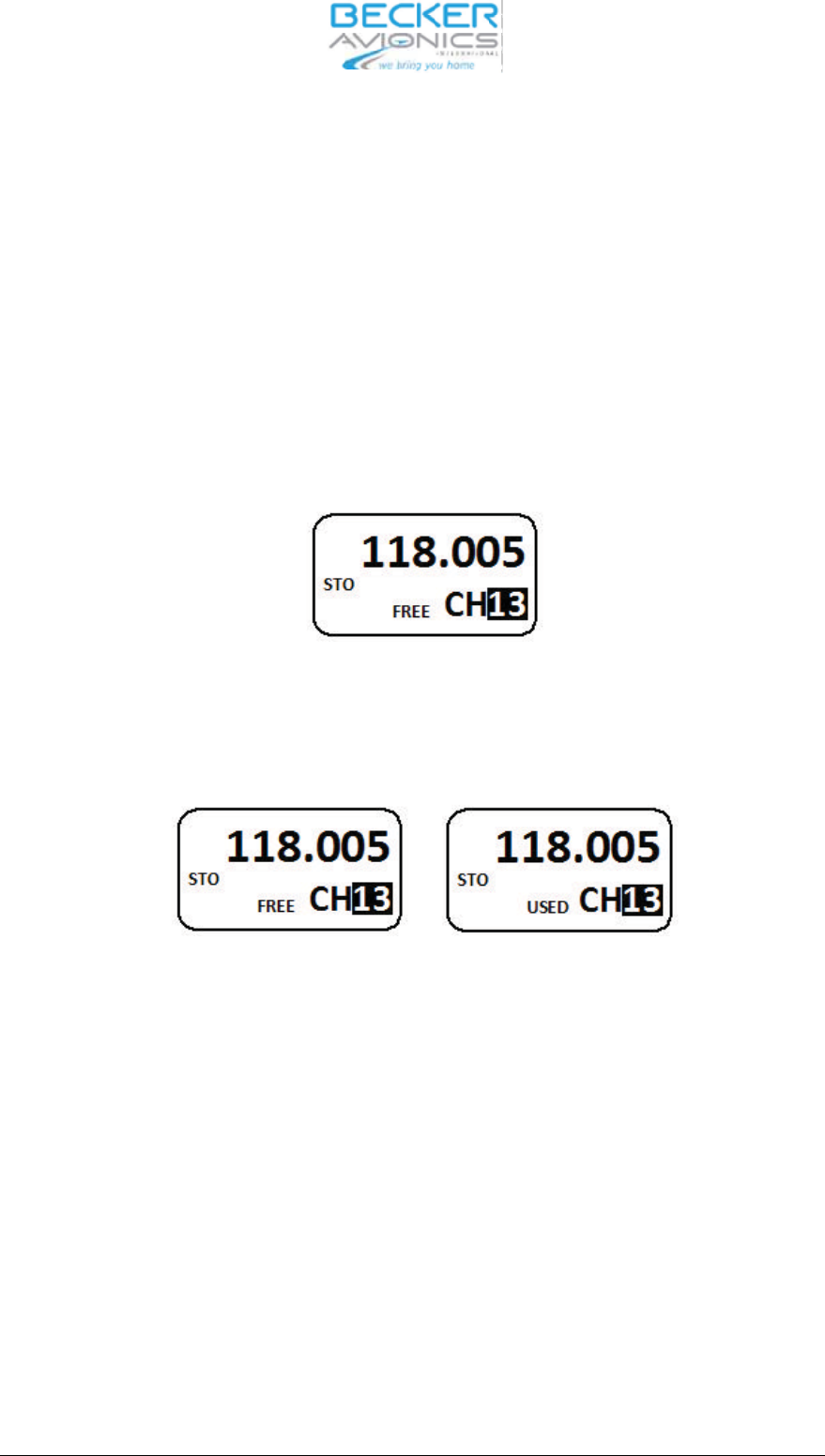
Sto ra ge functi on is ac ti vat ed as fol lows:
Short press of the STO key. On the top line ac ti ve fre quen cy is in di ca ted.
Chan nel num ber se lec ti on.
On the bot tom line chan nel num ber is in di ca ted; if chan nel is free, sign ”FREE” is dis played, ot her-
wi se ”USED” is dis play ed as fol lows:
“FREE” and “USED” chan nel in di ca ti on.
The chan nel di gits are in ver ted. By tur ning the Ro ta
ry en co der the chan nel num ber is in cre men ted
/ de cre men ted de pen ding on the tur ning di rec ti on in ran ge 10 … 99.
Short press of STO key. The trans cei ver sto res the fre quen cy into the se lec ted chan nel and goes
back to the pre vi ous mode.
If no ac ti on oc curs du ring 7 se conds the trans cei ver goes back to the pre vi ous mode wit hout sto -
ring the fre quen cy.
3.4.1 Au to ma tic sto ra ge functi on
The trans cei ver con tains a stan dard mode au to ma tic sto ra ge functi on. The last ac ti ve fre quen cy is
sto red in me mo ry chan nel 1(CH01). The ac ti ve fre quen cy pre vi ous ly lo ca ted in me mo ry chan nels
1, 2 … 8 is shif ted to me mo ry chan nels 2, 3 … 9. Fre quen cy chan nel pre vi ous ly lo ca ted in me
mo ry
chan nel 9 is lost.
Page 3-10 DV 14300.03/04 Issue 05/10
AR6201
Se lect chan nel 1 to 9
Se lect the chan nel mode by short press of the MDE key. In the top line of the dis play is the sto red
fre quen cy in di ca ted. In the lo wer line of the dis play, the chan nel num ber 10 is in di ca ted.
By a short press the Ro ta ry en co der Push but ton the chan nel num ber is in ver ted.
Se lect re qui red chan nel num ber by tur ning the Ro ta ry en co der coun ter clock wise.
Note:
A ti me out of 5 se conds is im ple men ted to ab ort se lec tion mode if no user ac tion oc curs.
Exit from chan nel se lec tion is achie ved by short pres sing the Ro ta ry en co der Push but ton.
3.5 In ter com settings
In ter com me nus give easy ac cess to set tings, for ex am ple:
❐In ter com vo lu me
❐VOX set tings (En ab le/Dis ab le VOX, VOX thres hold)
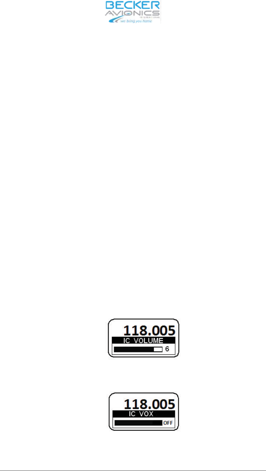
3.5.1 In ter com vo lu me / VOX set tings
The In ter com menu is ac ti vat ed by long press of IC/SQL key in all se lec tion mo des and
SCAN-Sub mode.
The ac ti ve fre quen cy is in di ca ted in the top line of the dis play. On the bot tom line is in di ca ted ”IC
Vo lu me ”with bar graph and va lue.
Se lect re qui red va lue by tur ning the Ro ta ry en co der (in cre men ted / de cre men ted de pen ding on
the tur ning di rec tion).
By a short press of the Ro ta ry en co der Push but ton the VOX set ting is ac ti vat ed. Se lect re qui red
va lue by tur ning the Ro ta ry en co der (in cre men ted / de cre men ted de pen ding on the tur ning di rec-
tion).
When VOX is switched OFF the dis play shows
AR6201
DV 14300.03/04 Issue 05/10 Page 3-11
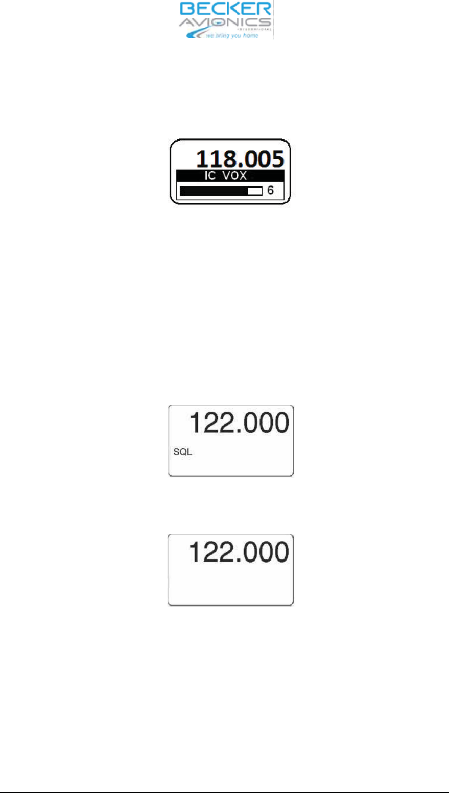
When VOX is switched ON the dis play in di ca teds bar ac cor ding to cur rent VOX thres hold va lue.
Note:
When VOX is ON (0..10) bar is not fil led.
The chan ge va lues is au to ma ti cal ly sto red 2 se cond af ter the last chan ge took pla ce.
3.6 Squelch functi on
Squelch functi on is ac ti vat ed as fol lows:
Short press of the SQL/IC key.
Squelch is tog gled bet ween ON and OFF sta te.
Squelch sta tus ON
Squelch sta tus OFF
AR6201
Page 3-12 DV 14300.03/04 Issue 05/10
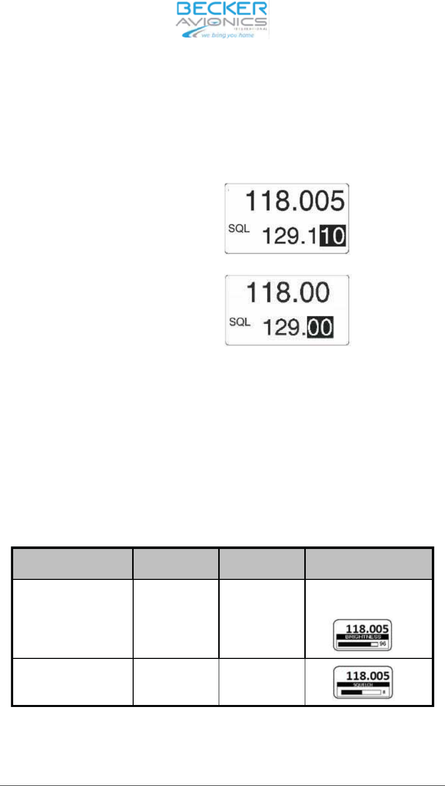
3.7 Chan nel spa cing swit cho ver 25 kHz to 8.33 kHz
The swit cho ver bet ween 25 kHz chan nel spa cing and 8.33 kHz chan nel spa cing is only pos si ble in
Stan dard mode and Di rect tune mode.The chan nel spa cing is chan ged by pres sing STO and MDE
keys simultaneously for at least 3 se conds.
8.33 kHz chan nel spa cing
25 kHz chan nel spa cing
3.8 Spe ci al set ting of bright ness and squelch thres hold
Spe ci al set tings se lec tion can be ac ti vat ed by long press of MDE key in all se lec ti on mo des.
The ac ti ve fre quen cy is in di ca ted in the top line of the dis play. In di ca ted bright ness value in the bot -
tom line of the dis play.
Short pres sing of Ro ta ry en co der push but ton. Set ting the va lue with Ro ta ry en co der and sto -
red the va lue by pres sing of the STO key.
Chan ge to squelch thres hold set ting by Short pres sing of Ro ta
ry en co der push but ton. Set the
va lue with Ro ta ry en co der and sto re the va lue by pres sing of the STO key.
Push ”ro ta ry en co der” Turn ”ro ta ry en -
co der”
Push ”sto” key View and Con di tions
BRIGHT NESS 0%..50%..100% Sto re im me di ate-
ly
Dis play ed only if Dim ming in put
is set to ”NONE”
SQUELCH
THRES HOLD
6 ... 12 dB Sto re im me di ate-
ly
En ding of the set tings by long press of MDE but ton.
DV 14300.03/04 Issue 05/10 Page 3-13
AR6201
3.9 Built-In Test
3.9.1 CBIT test re sults indication
The de vi ce is able to in di ca te Con ti nu ous BIT re sult du ring ope ra ti on. Ne ga ti ve re sults are in di ca-
ted on the dis play (Fai lu re or war ning mes sa ge is dis play ed).
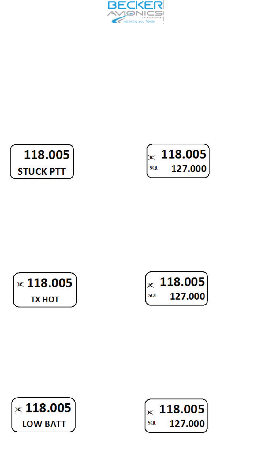
3.9.2 CBIT Stuck_PTT war ning
If the CBIT has de tec ted stuck PTT war ning, the dis play in di ca te it as fol lows:
war ning in di ca ti on nor mal ope ra ting
for 1se cond, than for 4 se conds.f
CBIT ”Stuck PTT” war ning in di ca ti on
3.9.3 CBIT TX_HOT war ning pre sen ta ti on mode
If the CBIT has de tec ted TX HOT war ning, the dis play in di ca tes as fol lows:
for 1 se cond than for 4 seconds
CBIT ”TX HOT” war ning in di ca ti on
3.9.4 CBIT LOW BAT TE RY war ning pre sen ta ti on mode
If the CBIT has de tec ted LOW BAT TE RY war
ning, the dis play in di ca tes as fol lows:
for 1 se cond than for 4 se conds
CBIT ”LOW BATT” war ning in di ca ti on.
AR6201
Page 3-14 DV 14300.03/04 Issue 05/10

3.9.5 CBIT TX_HOT, Stuck_PTT and LOW BAT TE RY war nings
If the CBIT has de tec ted TX HOT, Stuck PTT and LOW BAT TE RY war nings in any com bi na tions,
the dis play in di ca tes in se quen ce: 1st war ning (1 se cond), nor mal ope ra ti on (4 se conds), 2nd
war ning (1 se cond), nor mal ope ra ti on (4 se conds) and 3rd war ning (1 se cond), nor mal ope ra ti on
(4 se conds).
3.9.6 CBIT fai lu re
If the CBIT has de tec ted Fai lu re, the dis play in di cats as fol lows:
for 1 se cond than for 4 se cond
If the CBIT has de tec ted fai lu re to get her with TX HOT and / or Stuck PTT war nings, only fai lu re is
in di ca ted.
AR6201
DV 14300.03/04 Issue 05/10 Page 3-15

3.10 Sa fe ty in struc tions
The fol lo wing in struc tions must be fol lo wed for safe ope ra tion of the VHF trans cei ver:
❐Switch OFF the unit be fo re star ting or shut ting down en gi nes.
❐A speech test is to be per for med be fo re start up and it should be no ted that if the
speech test is car ried out clo se to the ground sta tion the re sults may be po si ti ve even
if the an ten na ca ble is bro ken or short-circuited. At a di stan ce of 5 to 10 km no con -
nec tion will be made.
❐Use a loud voi ce for speech com mu ni ca tion and hold the mi cro pho ne clo se to the
lips. Ot her wi se ca bin noi se can be in tru si ve and make un der stan ding dif fi cult.
❐Use only mi cro pho nes or he ad sets which are suit ab le for use in air craft. In air craft
made of wood or syn the tic ma te ri als or in gli ders or he li cop ters, in co ming ra dia tion on
the equip
ment an ten na can af fect the in te gra ted am pli fier of the mi cro pho ne (feed -
back). This is no ti ce ab le in the ground sta tion by whist ling and/or he avy di stor tion.
The des cri bed di stur ban ces can oc cur in dif fe rent ways on the dif fe rent trans mis sion
chan nels.
AR6201
Page 3-16 DV 14300.03/04 Issue 05/10