Becker Avionics ATC3401 Aviation Trasponder User Manual TIT IO
Becker Flugfunkwerk GmbH Aviation Trasponder TIT IO
UserManual.wiki
>
Becker Avionics
>
ATC3401 User Manual
Manual
Navigation menu
Upload a User Manual
Namespaces
Wiki Guide
HTML
PDF
Info
Views
User Manual
Discussion / Help
Navigation
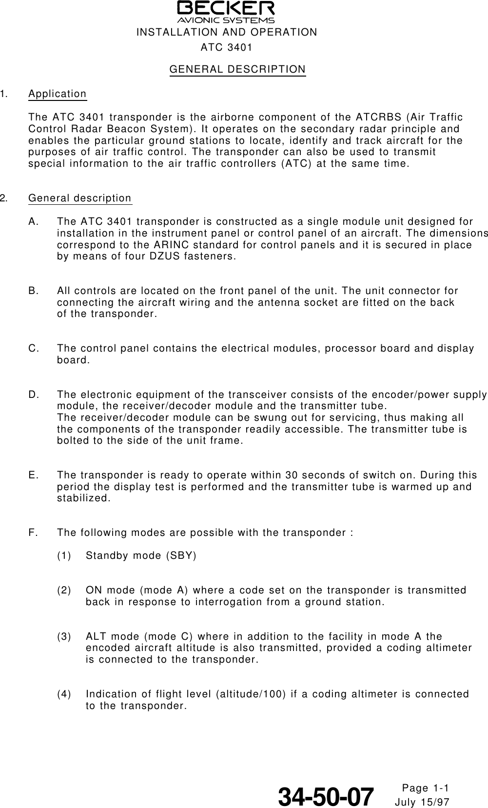
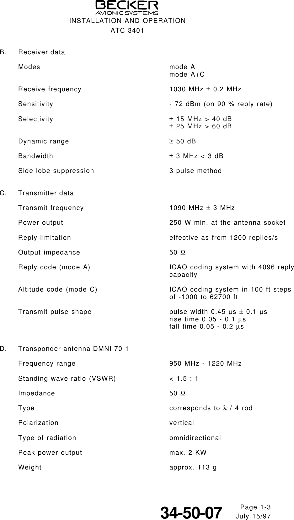
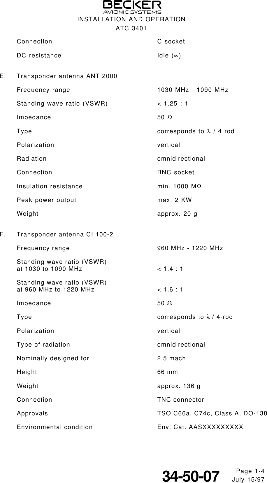
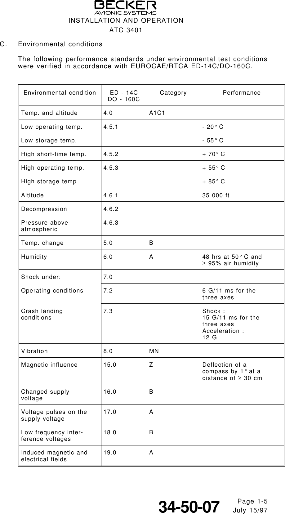
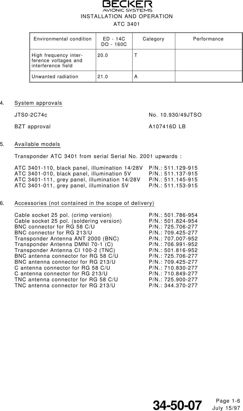
![(5) Additional identification information whereby the ident button of the trans-ponder is pressed on instructions from the air traffic controller. The iden-tification pulse (SPI pulse) transmitted in this case enables immediateidentification of the aircraft on the controller’s radar screen, by means ofan additional marking on the object display.(6) Test function by pressing the TEST push-button in which all digits flash in the displays and the reply lamp comes on.3. Technical dataA. General dataSupply voltage 10.0 V - 32.2 V DCCurrent consumption 1.5 A at 14 V(without panel lighting) 0.8 A at 28 V- in standby mode 0.5 A at 14 V0.3 A at 28 VPanel lighting typ. 480 mA at 14 Vtyp. 240 mA at 28 Vtyp. 1.5 A at 5 VWarm-up time approx. 30 sFuse protection 2 A medium-blowOperating temperature range - 20° C bis + 55° C (short-time + 70° C)Altitude max. 35 000 ft.EUROCAE/RTCA ED-14C/DO-160C Cat. A1 C1(no altitude limitation in pressurizedaircrafts)Vibration EUROCAE/RTCA ED-14C/DO-160C Cat. M+N(rigid mounted in all aircraftswithout limitations)Environmental conditions EUROCAE/RTCA ED-14C/DO-160CEnv. Cat. [A1C1]-BA(MN)XXXXXXZBABATAXXXWeight 1.2 kgMechanical dimensionsFront panel 47.5 x 146 mm (H x W)Case depth 217 mm above antenna socketTest and assembly standards JTSO-C74c Class 1ARTCA DO-150 Cat. B.(cat. A conversion possible)INSTALLATION AND OPERATIONATC 3401Page 1-234-50-07 July 15/97](https://usermanual.wiki/Becker-Avionics/ATC3401/User-Guide-49090-Page-8.png)