Becker Avionics ATC3401 Aviation Trasponder User Manual TIT IO
Becker Flugfunkwerk GmbH Aviation Trasponder TIT IO
Manual

Transponder
ATC 3401
from Serial No. 2001 upwards
INSTALLATION AND OPERATION
Becker Flugfunkwerk GmbH
Baden Airpark Postfach 34 76549 Hügelsheim
Tel. 07229 / 3050 Fax 07229 / 305217
34-50-07 July 15/97
DV 63803.03
© 1997 by Becker Flugfunkwerk GmbH
All rights reserved

LIST OF EFFECTIVE PAGES
SUBJECT PAGE DATE SUBJECT PAGE DATE
Title Page 1 July 15/97
List of Effective
Page 1 July 15/97
Table of Contents 1 July 15/97
Introduction 1 July 15/97
General
Description I-I July 15/97
1-1 July 15/97
1-2 July 15/97
1-3 July 15/97
1-4 July 15/97
1-5 July 15/97
1-6 July 15/97
Installation II-I July 15/97
2-1 July 15/97
2-2 July 15/97
2-3 July 15/97
2-4 July 15/97
2-5 July 15/97
2-6 July 15/97
2-7 July 15/97
2-8 July 15/97
2-9 July 15/97
2-10 July 15/97
2-11 July 15/97
2-12 July 15/97
2-13 July 15/97
2-14 July 15/97
Operation III-I July 15/97
3-1 July 15/97
3-2 July 15/97
3-3 July 15/97
3-4 July 15/97
3-5 July 15/97
3-6 July 15/97
3-7 July 15/97
3-8 Blank
INSTALLATION AND OPERATION
ATC 3401
LEP Seite 1
34-50-07 July 15/97

TABLE OF CONTENTS
Page
INTRODUCTION 1
GENERAL DESCRIPTION 1-1
INSTALLATION 2-1
OPERATION 3-1
INSTALLATION AND OPERATION
ATC 3401
TOC Page 1
34-50-07 July 15/97

INTRODUCTION
1. General
This component maintenance manual describes the BECKER transponder
ATC 3401 from serial No. 2001 upwards.
2. Manufacturing
The transponder ATC 3401 is manufactured and product supported by :
Becker Flugfunkwerk GmbH
Baden Airpark
P.O. Box 34
76549 Hügelsheim
Germany
Telephone: 0 72 29 - 305 - 0
Telex: 78 12 71
Telefax: 0 72 29 - 305 - 217
3. Layout of manual
The manual is divided into three sections. Section 1 contains the general descripti-
on of the transponder and gives the technical data. Section 2 describes the instal-
lation instructions and Section 3 the operation of the unit.
INSTALLATION AND OPERATION
ATC 3401
INTRO Page 1
34-50-07 July 15/97

Table of contents
GENERAL DESCRIPTION Page
1. Application 1-1
2. General description 1-1
3. Technical data 1-2
4. System approvals 1-6
5. Available models 1-6
6. Accessories (not contained in the scope of delivery) 1-6
INSTALLATION AND OPERATION
ATC 3401
Page I-I
34-50-07 July 15/97

GENERAL DESCRIPTION
1. Application
The ATC 3401 transponder is the airborne component of the ATCRBS (Air Traffic
Control Radar Beacon System). It operates on the secondary radar principle and
enables the particular ground stations to locate, identify and track aircraft for the
purposes of air traffic control. The transponder can also be used to transmit
special information to the air traffic controllers (ATC) at the same time.
2. General description
A. The ATC 3401 transponder is constructed as a single module unit designed for
installation in the instrument panel or control panel of an aircraft. The dimensions
correspond to the ARINC standard for control panels and it is secured in place
by means of four DZUS fasteners.
B. All controls are located on the front panel of the unit. The unit connector for
connecting the aircraft wiring and the antenna socket are fitted on the back
of the transponder.
C. The control panel contains the electrical modules, processor board and display
board.
D. The electronic equipment of the transceiver consists of the encoder/power supply
module, the receiver/decoder module and the transmitter tube.
The receiver/decoder module can be swung out for servicing, thus making all
the components of the transponder readily accessible. The transmitter tube is
bolted to the side of the unit frame.
E. The transponder is ready to operate within 30 seconds of switch on. During this
period the display test is performed and the transmitter tube is warmed up and
stabilized.
F. The following modes are possible with the transponder :
(1) Standby mode (SBY)
(2) ON mode (mode A) where a code set on the transponder is transmitted
back in response to interrogation from a ground station.
(3) ALT mode (mode C) where in addition to the facility in mode A the
encoded aircraft altitude is also transmitted, provided a coding altimeter
is connected to the transponder.
(4) Indication of flight level (altitude/100) if a coding altimeter is connected
to the transponder.
INSTALLATION AND OPERATION
ATC 3401
Page 1-1
34-50-07 July 15/97

(5) Additional identification information whereby the ident button of the trans-
ponder is pressed on instructions from the air traffic controller. The iden-
tification pulse (SPI pulse) transmitted in this case enables immediate
identification of the aircraft on the controller’s radar screen, by means of
an additional marking on the object display.
(6) Test function by pressing the TEST push-button in which all digits flash
in the displays and the reply lamp comes on.
3. Technical data
A. General data
Supply voltage 10.0 V - 32.2 V DC
Current consumption 1.5 A at 14 V
(without panel lighting) 0.8 A at 28 V
- in standby mode 0.5 A at 14 V
0.3 A at 28 V
Panel lighting typ. 480 mA at 14 V
typ. 240 mA at 28 V
typ. 1.5 A at 5 V
Warm-up time approx. 30 s
Fuse protection 2 A medium-blow
Operating temperature range - 20° C bis + 55° C (short-time + 70° C)
Altitude max. 35 000 ft.
EUROCAE/RTCA ED-14C/
DO-160C Cat. A1 C1
(no altitude limitation in pressurized
aircrafts)
Vibration EUROCAE/RTCA ED-14C/
DO-160C Cat. M+N
(rigid mounted in all aircrafts
without limitations)
Environmental conditions EUROCAE/RTCA ED-14C/DO-160C
Env. Cat. [A1C1]-BA(MN)XXXXXX
ZBABATAXXX
Weight 1.2 kg
Mechanical dimensions
Front panel 47.5 x 146 mm (H x W)
Case depth 217 mm above antenna socket
Test and assembly standards JTSO-C74c Class 1A
RTCA DO-150 Cat. B.
(cat. A conversion possible)
INSTALLATION AND OPERATION
ATC 3401
Page 1-2
34-50-07 July 15/97

B. Receiver data
Modes mode A
mode A+C
Receive frequency 1030 MHz ± 0.2 MHz
Sensitivity - 72 dBm (on 90 % reply rate)
Selectivity ± 15 MHz > 40 dB
± 25 MHz > 60 dB
Dynamic range ≥ 50 dB
Bandwidth ± 3 MHz < 3 dB
Side lobe suppression 3-pulse method
C. Transmitter data
Transmit frequency 1090 MHz ± 3 MHz
Power output 250 W min. at the antenna socket
Reply limitation effective as from 1200 replies/s
Output impedance 50 Ω
Reply code (mode A) ICAO coding system with 4096 reply
capacity
Altitude code (mode C) ICAO coding system in 100 ft steps
of -1000 to 62700 ft
Transmit pulse shape pulse width 0.45 µs ± 0.1 µs
rise time 0.05 - 0.1 µs
fall time 0.05 - 0.2 µs
D. Transponder antenna DMNI 70-1
Frequency range 950 MHz - 1220 MHz
Standing wave ratio (VSWR) < 1.5 : 1
Impedance 50 Ω
Type corresponds to λ / 4 rod
Polarization vertical
Type of radiation omnidirectional
Peak power output max. 2 KW
Weight approx. 113 g
INSTALLATION AND OPERATION
ATC 3401
Page 1-3
34-50-07 July 15/97

Connection C socket
DC resistance Idle (∞)
E. Transponder antenna ANT 2000
Frequency range 1030 MHz - 1090 MHz
Standing wave ratio (VSWR) < 1.25 : 1
Impedance 50 Ω
Type corresponds to λ / 4 rod
Polarization vertical
Radiation omnidirectional
Connection BNC socket
Insulation resistance min. 1000 MΩ
Peak power output max. 2 KW
Weight approx. 20 g
F. Transponder antenna CI 100-2
Frequency range 960 MHz - 1220 MHz
Standing wave ratio (VSWR)
at 1030 to 1090 MHz < 1.4 : 1
Standing wave ratio (VSWR)
at 960 MHz to 1220 MHz < 1.6 : 1
Impedance 50 Ω
Type corresponds to λ / 4-rod
Polarization vertical
Type of radiation omnidirectional
Nominally designed for 2.5 mach
Height 66 mm
Weight approx. 136 g
Connection TNC connector
Approvals TSO C66a, C74c, Class A, DO-138
Environmental condition Env. Cat. AASXXXXXXXXX
INSTALLATION AND OPERATION
ATC 3401
Page 1-4
34-50-07 July 15/97

G. Environmental conditions
The following performance standards under environmental test conditions
were verified in accordance with EUROCAE/RTCA ED-14C/DO-160C.
Environmental condition ED - 14C
DO - 160C Category Performance
Temp. and altitude 4.0 A1C1
Low operating temp. 4.5.1 - 20° C
Low storage temp. - 55° C
High short-time temp. 4.5.2 + 70° C
High operating temp. 4.5.3 + 55° C
High storage temp. + 85° C
Altitude 4.6.1 35 000 ft.
Decompression 4.6.2
Pressure above
atmospheric 4.6.3
Temp. change 5.0 B
Humidity 6.0 A48 hrs at 50° C and
≥ 95% air humidity
Shock under: 7.0
Operating conditions 7.2 6 G/11 ms for the
three axes
Crash landing
conditions 7.3 Shock :
15 G/11 ms for the
three axes
Acceleration :
12 G
Vibration 8.0 MN
Magnetic influence 15.0 ZDeflection of a
compass by 1° at a
distance of ≥ 30 cm
Changed supply
voltage 16.0 B
Voltage pulses on the
supply voltage 17.0 A
Low frequency inter-
ference voltages 18.0 B
Induced magnetic and
electrical fields 19.0 A
INSTALLATION AND OPERATION
ATC 3401
Page 1-5
34-50-07 July 15/97

Environmental condition ED - 14C
DO - 160C Category Performance
High frequency inter-
ference voltages and
interference field
20.0 T
Unwanted radiation 21.0 A
4. System approvals
JTS0-2C74c No. 10.930/49JTSO
BZT approval A107416D LB
5. Available models
Transponder ATC 3401 from serial Serial No. 2001 upwards :
ATC 3401-110, black panel, illumination 14/28V P/N.: 511.129-915
ATC 3401-010, black panel, illumination 5V P/N.: 511.137-915
ATC 3401-111, grey panel, illumination 14/28V P/N.: 511.145-915
ATC 3401-011, grey panel, illumination 5V P/N.: 511.153-915
6. Accessories (not contained in the scope of delivery)
Cable socket 25 pol. (crimp version) P/N.: 501.786-954
Cable socket 25 pol. (soldering version) P/N.: 501.824-954
BNC connector for RG 58 C/U P/N.: 725.706-277
BNC connector for RG 213/U P/N.: 709.425-277
Transponder Antenna ANT 2000 (BNC) P/N.: 707.007-952
Transponder Antenna DMNI 70-1 (C) P/N.: 706.991-952
Transponder Antenna CI 100-2 (TNC) P/N.: 501.816-952
BNC antenna connector for RG 58 C/U P/N.: 725.706-277
BNC antenna connector for RG 213/U P/N.: 709.425-277
C antenna connector for RG 58 C/U P/N.: 710.830-277
C antenna connector for RG 213/U P/N.: 710.849-277
TNC antenna connector for RG 58 C/U P/N.: 725.900-277
TNC antenna connector for RG 213/U P/N.: 344.370-277
INSTALLATION AND OPERATION
ATC 3401
Page 1-6
34-50-07 July 15/97

Table of contents
INSTALLATON Page
1. General 2-1
2. Inspection before installation 2-1
3. Mechanical configuration 2-3
4. Aircraft wiring 2-3
5. Installing the transponder antenna 2-6
6. Checking after installation 2-6
Fig. 2-1 Test setup 2-8
Fig. 2-2 Dimensions ATC 3401 2-9
Fig. 2-3 Installation of fastener strips 2-10
Fig. 2-4 Dimensions DMNI 70-1 2-11
Fig. 2-5 Dimensions ANT 2000 2-12
Fig. 2-6 Dimensions CI 100-2 2-13
Fig. 2-7 Installation wiring ATC 3401 2-14
INSTALLATION AND OPERATION
ATC 3401
Page II-I
34-50-07 July 15/97

INSTALLATION
1. General
Installation of the transponder ATC 3401 depends on the aircraft type and its
equipment. Therefore, only general information can be provided in this Section.
2. Inspection before installation
Before the transponder is installed in an aircraft, a visual inspection for possible
transport damages shall be performed.
A. Visual inspection
Please look out for the following defects:
(1) Dirt, dents, scratches, corrosion, broken fastening elements on housing
and housing parts.
(2) Dirt and scratches on nameplate, front plate and inscriptions.
(3) Dirt, bent or broken pins, cracked insert of unit connector and antenna
socket.
(4) Dirt, stiffness and mechanical damage to the pushbuttons, rotary switches
and LC displays.
(5) Missing screws.
B. Checking procedure
Connect the transponder to the test setup as shown in Fig. 2-1 and carry out
the following tests in the given sequence. Instead of the transponder test set
SQUAWK/NAUT I an equivalent test set or a ramp test set can be used.
(1) Checking receiver sensitivity
(a) Set SQUAWK/NAUT I to mode A on and 400 interrogations per
second. Note that the amplitude of pulse P 2 is ≤ - 9 dB of pulse
P 1.
(b) Note that pulses P 1 and P 3 have equal amplitudes. Set the RF
input level to - 72 dB and observe that the transponder replies to
at least 90 % of the interrogations.
(c) Set SQUAWK/NAUT I to mode C and repeat test.
INSTALLATION AND OPERATION
ATC 3401
Page 2-1
34-50-07 July 15/97

(2) Checking side lobe suppression (SLS)
(a) Set SQUAWK/NAUT I to mode A on and 400 interrogations per
second.
(b) Set pulses P 1 and P 2 to same amplitude.
(c) Alter the HF input level from - 69 dBm to - 24 dBm, whereby the
transponder must reply to not more than 1 % of the interrogation
pulses.
(3) Checking reply pulses
(a) Set SQUAWK/NAUT I to mode A at and 400 interrogations per
second. Set pulses P 1 and P 3 to - 60 dBm.
(b) Transmit frequency must be 1090 MHz ± 3 MHz.
(c) The output power shall be ≥ 250 W of the antenna terminal.
CAUTION : If RG 58 C/U is used as indicated in the test
setup Fig. 2-1, the cable attenuation of app. 1 dB
will reduce the output power by app. 50 W.
(d) Pulse spacing between the frame pulses F 1 and F 2 must be
20.3 µs ± 0.1 µs.
(e) The width of a reply pulse must be 0.45 µs ± 0.1 µs.
(f) The necessary spacing between the reply pulses is 1.45 µs
± 0.1 µs.
(4) Checking reply limiting (AOC)
Set SQUAWK/NAUT I to max. interrogation rate at which the transpon-
der must respond with min. 1200 replies/s.
(5) Checking the SPI hold time
(a) Briefly press the IDENT button on the transponder.
(b) For approx. 15 - 30 seconds, the SPI pulse must appear after the
last frame pulse F 2 at a spacing of 4.35 µs.
INSTALLATION AND OPERATION
ATC 3401
Page 2-2
34-50-07 July 15/97

(6) Checking mode A coding
(a) Set code 0000 on the transponder, resulting in only the frame pulses
F 1 and F 2 being visible on the oscilloscope.
(b) Set code 7777, this must produce all 12 reply pulses including the
frame pulses on the oscilloscope.
(7) Checking mode C coding
If a coding altimeter is connected to the transponder, check with the
aid of the MoA Gilham code whether the coded pulse sequence agrees
with the measured altitude. If the coding altimeter is not connected to
the transponder it transmits in mode C operation the frame pulses only.
3. Mechanical configuration
A. The transponder ATC 3401 is designed for installation aircraft instrument panel
or control panel. The dimensions for installation of the transponder are shown
in Fig. 2-2.
B. Fitting the fastener strips e.g. on the instrument panel is shown in Fig. 2-3. The
transponder is mounted after fitting the fastener strips with the aid of four DZUS
fasteners.
4. Aircraft wiring
A. The aircraft wiring of the transponder together with the connection to the enco-
ding altimeter is shown in Fig. 2-7.
CAUTION : The transponder supply lines must not be loomed together with
other equipment looms. In addition care must be taken to avoid
running all transponder wiring in the close vicinity of ADF or other
pulse equipment looms.
INSTALLATION AND OPERATION
ATC 3401
Page 2-3
34-50-07 July 15/97

B. Pin connections of the unit connector
Connector : P 8
Pin :
1Ident button external
2TX-B (RS 422)
3Illumination + 14 V (5 V)
4Illumination + 28 V (5 V)
5TX-A (RS422)
6Switched output +10 . . . 32 V (encoding altimeter)
7RX-B (RS 422)
8TX-A (RS 422)
9FUNCTION ON external
10 DME/transponder suppression
11 Supply voltage GND
12 Supply voltage GND
13 Supply voltage +10 . . . 32 V DC
14 Altitude pulse A 4
15 Altitude pulse A 2
16 Altitude pulse A 1
17 Altitude pulse B 1
18 Altitude pulse B 4
INSTALLATION AND OPERATION
ATC 3401
Page 2-4
34-50-07 July 15/97

Pin :
19 Altitude pulse B 2
20 Altitude pulse C 4
21 Altitude pulse C 2
22 Altitude pulse C 1
23 Altitude pulse D 4
24 Altitude encoding GND
25 Supply voltage +10 . . . 32 V DC
C. External IDENT push-button
If this input (Pin 1 of unit connector P8) is briefly connected to GND (e.g. by
an external push-button, the IDENT function is started in the same way as
with the IDENT push-button on the front panel.
D. DME suppression
If required, connnect the suppression in/out of transponder (pin 10 of unit con-
nector P8) with the corresponding pin of the DME unit with type RG 178 B/U
cable.
INSTALLATION AND OPERATION
ATC 3401
Page 2-5
34-50-07 July 15/97

5. Installing the transponder antenna
A. The transponder antenna is fitted to the underside of the aircraft fuselage at a
horizontal, flat location in the longitudinal direction. This location should not be
in the "shadow" of aircraft structure items. The highest range is achievied when
the antenna is located at the low point on the aircraft fuselage.
B. The installation dimensions of the transponder antennas are shown in Fig. 2-4
to Fig. 2-6.
CAUTION :
•Tranponder antenna DMNI 70-1 is provided with a cork gasket which
must be interposed between the skin of the aircraft and the anten-
na. To mount the antenna use only stainless screws in conjunction
with lock washers.
•The transponder antenna ANT 2000 is provided with a silicone rub-
ber gasket which must also be interposed between the skin of the
aircraft and the antenna.
•In aircraft having a wooden or plastic airframe an electric counter-
weight plate or panel must be located within the fuselage at the an-
tenna location with minimum dimension 40 x 40 cm.
(1) Antenna cable
Use type RG 58 C/U coaxial cable when a length of 3 m or less is requi-
red. Use type RG 213/U when the length exceeds 3 m.
CAUTION : Keep the antenna cable as short as possible so that as litt-
le power is dissipated in the cable as possible.
6. Checking after installation
A. General
After the installation, check the transponder to ensure satisfactory operation
of the unit. The transmit frequency is to be checked and to be adjusted if
necessary.
B. Checking procedure
Carry out post installation check following the description of section 2./B. uti-
lizing a ramp test set.
INSTALLATION AND OPERATION
ATC 3401
Page 2-6
34-50-07 July 15/97

C. Test and adjustment of transmit frequency
Set code 0000 on the transponder and mode A interrogation on the ramp test
set. Check transmit frequency by means of the ramp test set. Transmit fre-
quency must be 1090 ± 3 MHz. If necessary use special wrench (1/4") loo-
sen trimmnut through the hole in the top cover and adjust transmit frequency
by means of the tuning screw.
CAUTION : After adjustment carefully tighten the trimmnut.
D. Pre-flight check using self test
(1) Activate the self test by pressing the TEST push-button (K). All digits
in the displays flash and the reply lamp (J) comes on.
(2) The EEPROM will be automatic tested with every write access. A failure
is indicated by "EE" in the left display and by "FAIL" in the right display.
INSTALLATION AND OPERATION
ATC 3401
Page 2-7
34-50-07 July 15/97
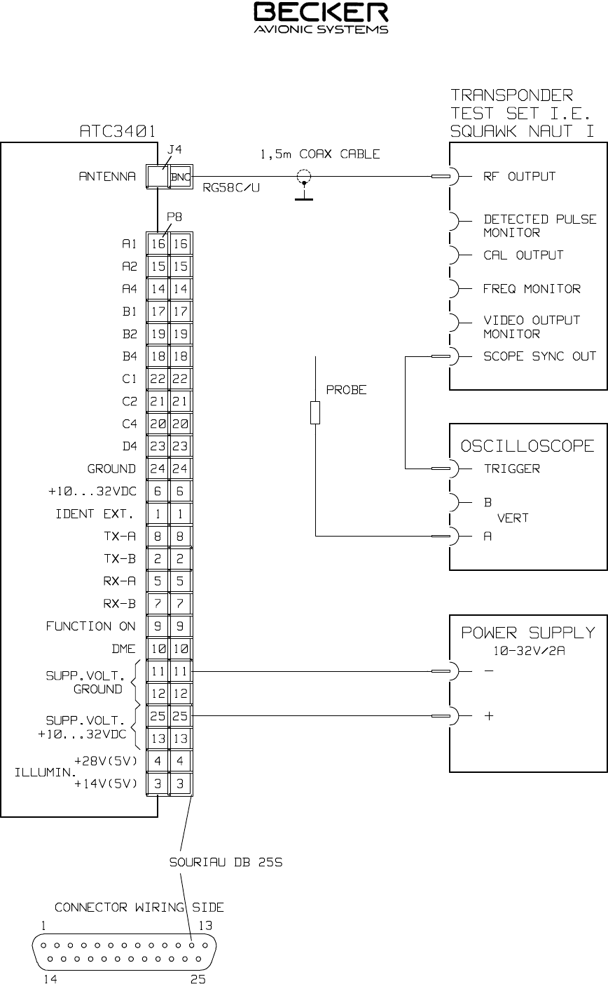
Fig. 2-1 Test setup
INSTALLATION AND OPERATION
ATC 3401
Page 2-8
34-50-07 July 15/97
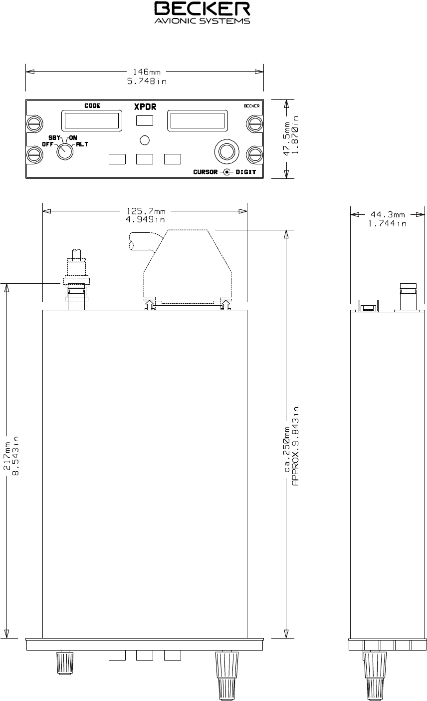
Fig. 2-2 Dimensions ATC 3401
INSTALLATION AND OPERATION
ATC 3401
Page 2-9
34-50-07 July 15/97
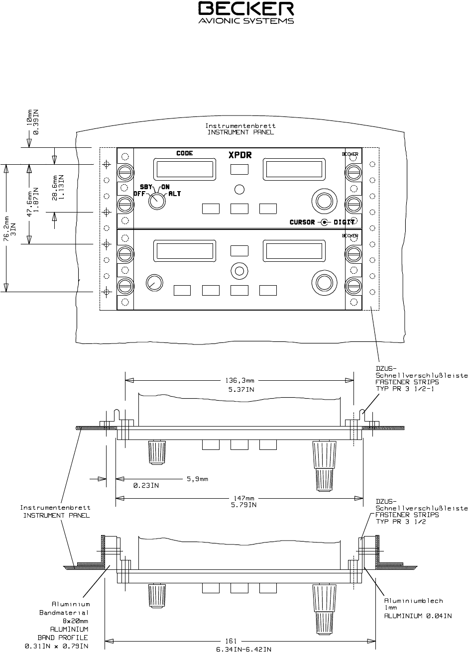
Fig. 2-3 Installation of fastener strips
INSTALLATION AND OPERATION
ATC 3401
Page 2-10
34-50-07 July 15/97
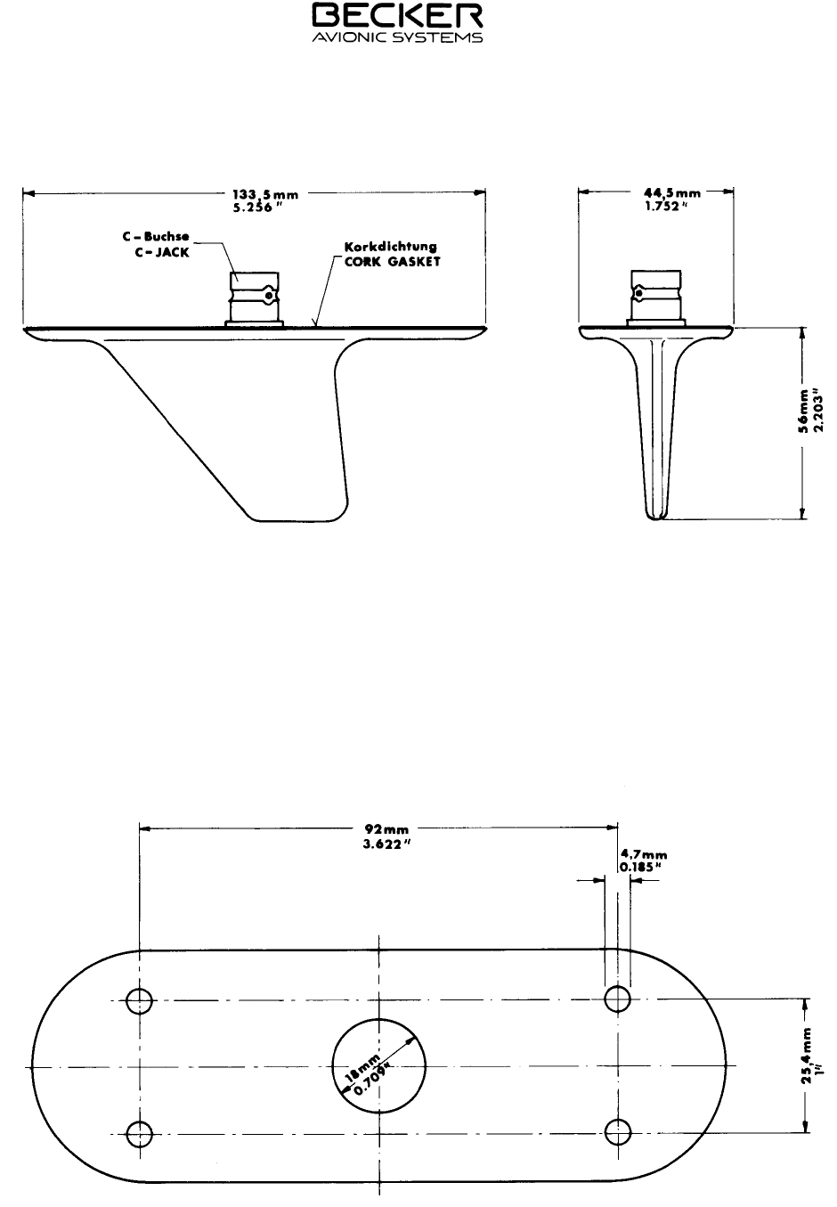
Fig. 2-4 Dimensions DMNI 70-1
INSTALLATION AND OPERATION
ATC 3401
Page 2-11
34-50-07 July 15/97
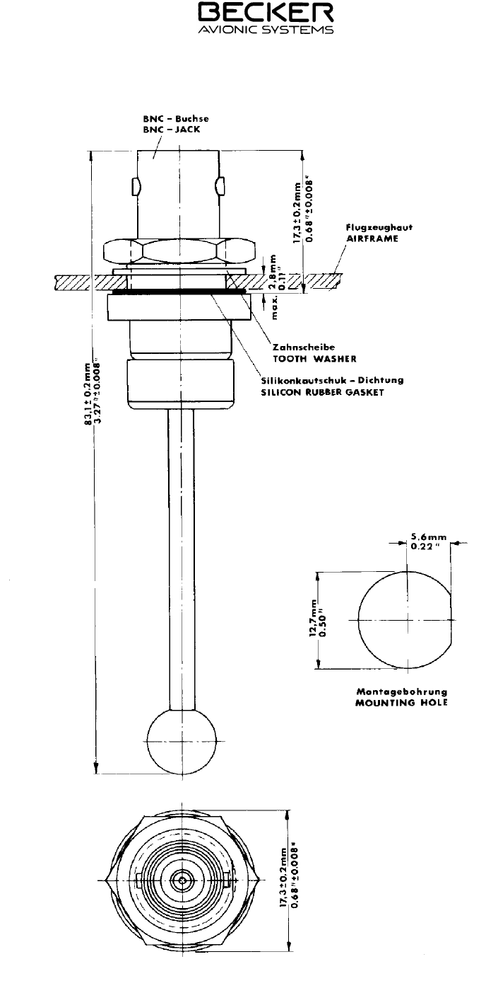
Fig. 2-5 Dimensions ANT 2000
INSTALLATION AND OPERATION
ATC 3401
Page 2-12
34-50-07 July 15/97
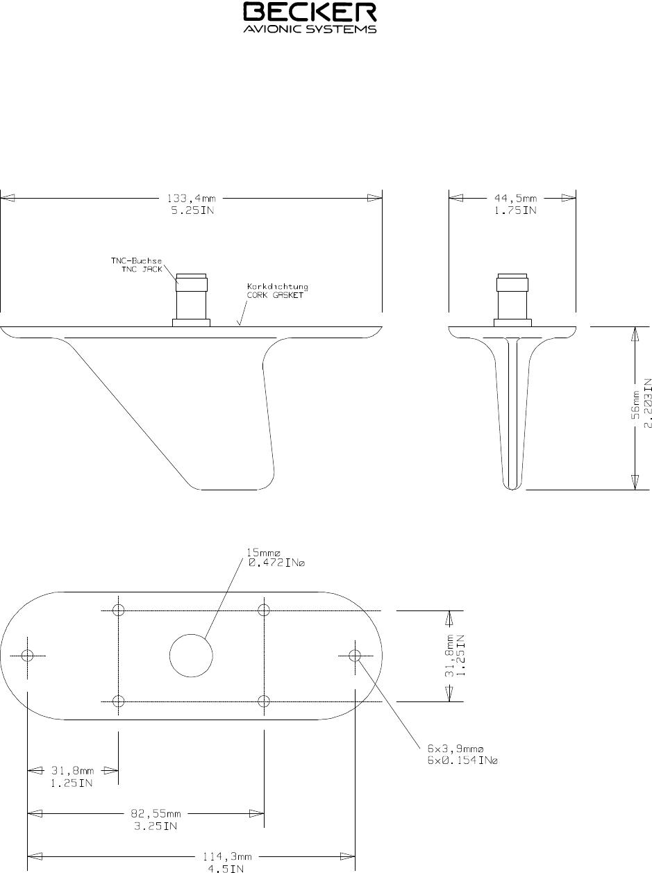
Fig. 2-6 Dimensions CI-100-2
INSTALLATION AND OPERATION
ATC 3401
Page 2-13
34-50-07 July 15/97
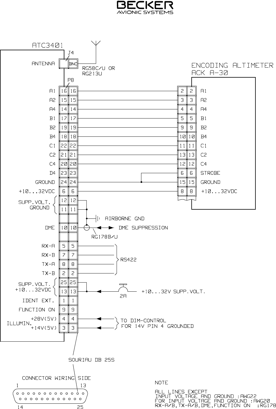
Fig. 2-7 Installation wiring ATC 3401
INSTALLATION AND OPERATION
ATC 3401
Page 2-14
34-50-07 July 15/97

TABLE OF CONTENTS
OPERATION Page
1. Controls and indicators 3-1
2. Funtion of controls and indicators 3-1
3. Transponder operating instructions 3-2
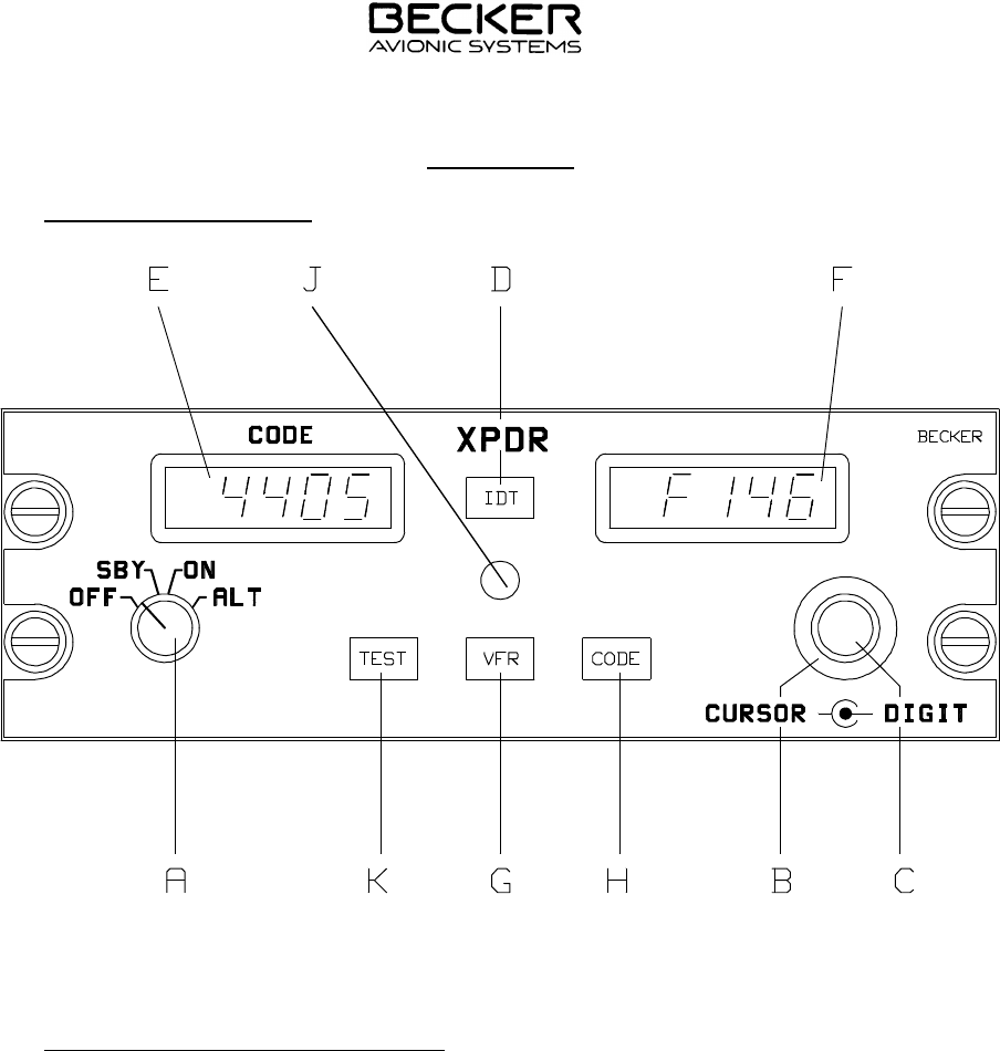
Fig. 3-1 Front panel of ATC 3401 3-1
INSTALLATION AND OPERATION
ATC 3401
Seite III-I
34-50-07 July 15/97
OPERATION
1. Controls and indicators
Fig. 3-1 Front panel of ATC 3401
2. Function of controls and indicators
A. OFF/SBY/ON/ALT OFF position : Transponder is switched off
rotary mode switch (exept panel ligthing).
with 4 lock positions SBY position : Standby is switched on.
ON position : ON mode (Mode A) is switched on.
ALT position : ALT mode (Modes A+C) is switched on.
B. Rotary coding switch Control of the cursor in one of the 4 code digits
with 8 lock positions, or from the display field.
continuously rotable
C. Rotary coding switch Setting the code digits from 0 to 7.
with 8 lock positions,
continuously rotable
D. Identification push-button In the ON and ALT modes this triggers the trans-
IDT mission of an identification impulse additional to the
Mode A reply code for approximately 25 seconds.
INSTALLATION AND OPERATION
ATC 3401
Page 3-1
34-50-07 July 15/97

E. Left LC display Code indication :
Codes from 0000 to 7777 are possible.
F. Right LC display Mode indication and flight level indication :
SBY mode :
"SBY" is displayed. This display flashes during the
warm up phase, i.e. for 30 seconds after power on.
ON mode :
"On" appears in the display.
ALT mode :
If a valid altitude code is present, the flight level
(height in steps of 100 ft) preceded by F (e.g. "F241"
= 24100 ft) appears. If no valid altitude code is pre-
sent, "F " is displayed.
"Idt" is displayed for the duration of the identification
function.
G. Code push-button Activates a user-specific VFR code.
VFR
H. Code push-button Activates a user-specific transponder reply code.
CODE
J. Reply lamp The green LED signals a transponder reply and/or
REPLY activation of the identification function.
K. Test push-button Activates the test function.
TEST
3. Transponder operating instructions
A. Switch on the unit (preflight check)
(1) Check that the circuit breaker is set and switch on the aircraft power
supply.
WARNING : Do not switch on the transponder if the motors or engines
are being started or shut down.
(2) Using the mode switch (A), switch the transponder from OFF to SBY.
A display test then follows for 3 seconds.
(3) The transponder is in the warm up phase for 30 seconds after power on.
After the display test (3 seconds) has elapsed, "SBY" flashes for 27 seconds
in the mode display. The transponder cannot transmit during this time.
(4) After the warm up phase has elapsed, the transponder switches to the
mode set on the mode switch (A).
INSTALLATION AND OPERATION
ATC 3401
Page 3-2
34-50-07 July 15/97

B. Flight operation in the ON mode (transponder reply code only)
(1) The transponder remains switched in the standby mode until requested
from the ground station (ATC) to send a code, e.g. "squawk alpha 6426".
(2) Check the code display. Do not set a code with 75XX/76XX/77XX. These
codes are reserved for emergencies.
(3) Using the double rotary switch (B,C), set the 4-digit code requested by
ATC as follows.
(a) Using switch (B) move the cursor to the particular digit. Digits 0 to 7
can then be set using switch (C).
NOTE : If switch (B) is turned clockwise or counterclockwise,
the cursor is moved one position to the left or the
right. The cursor appears only in the code display and
is indicated by the flashing digit. If no cursor is visible,
the first digit flashes after a clockwise rotation and the
last digit after a counterclockwise rotation. When the
code is being changed in the ON or ALT position, the
transponder replies not of incoming interrogations.
The active time of the cursor and the rate of flashing
can be changed in the configuration mode.
(b) If the cursor is not moved again within 3 seconds (can be changed in
the configuration mode) or if the cursor is moved so far that it can no
longer be seen in the display field or if the ident push-button (D) is
pressed (in the ON or ALT modes only), the code currently set is
switched active.
NOTE : Whilst settings are taking place, the transmission branch of the
transponder is inhibited to prevent unintentional transmission.
If only two digits were named by ATC, e.g. "squawk alpha 64", then
a zero is to be used for positions three and four, i.e. "6400".
(4) Set mode switch (A) from SBY to ON. The transponder immediately replies
with the set code. The green LED signals the transponder replies.
(5) After a "squawk ident" request from ATC, press ident push-button (D)
briefly. This transmits an additional, special impulse (SPI) for approxima-
tely 25 seconds, which enables the aircraft to be clearly identified on the
radar screen of the controller. Idt appears in the right LC display (F) during
this time.
(6) The last used code is stored in each case and is also activated when the
transponder is switched on.
INSTALLATION AND OPERATION
ATC 3401
Page 3-3
34-50-07 July 15/97

(7) During the approach, ATC normally gives the instruction "squawk standby".
The transponder must then be immediately switched to SBY using mode
switch (A), because the high transmission power of the unit can cause
disturbance on the radar screen. The transponder remains in the standby
mode until a new instruction to transmit is received.
C. Flight operation in the ALT mode (reply code and altitude code)
(1) If ATC requests the transmission "alpha/charlie" or "charlie", switch the
transponder to ALT using mode switch (A).
NOTE : This only makes sense if the transponder is connected to a
coding altimeter. If not, tell ATC that you do not have a mode C
("mode charlie not available").
(2) The transponder replies using the code set under Section B and in res-
ponse to mode C requests it transmits the flight level of the aircraft to ATC.
The green LED (J) signals the transponder replies.
(3) After "squawk ident" request from ATC, press the ident push-button (D)
briefly. This transmits an additional special impulse (SPI) for approxima-
tely 25 seconds which enables the aircraft to be clearly identified on the
radar screen of ATC. Idt appears in the right LC display (F) during this time.
(4) During the approach, ATC normally gives the instruction "squawk standby".
The transponder must then be switched to SBY using mode switch (A),
because the high transmission power of the unit can cause disturbance on
the radar screen. The Transponder remains in the standby mode until a
new request to send is received.
D. Special codings
(1) Two user-specific transponder codes can be stored on the transponder and
activated :
Push-button (G) : User-defined VFR code.
Push-button (H) : User-defined transponder code.
(2) Storing a new code.
(a) Set the code to be stored in accordance with Section B.
(b) Press VFR button (G) or CODE button (H) and hold for at least three
seconds. The old stored code first appears in the left display (E) and
this is followed after three seconds by the new code, which is stored
at the same time.
INSTALLATION AND OPERATION
ATC 3401
Page 3-4
34-50-07 July 15/97

(3) Activation of a stored code
(a) Press the VFR button (G) or CODE button (H). The selected code is
then displayed. After 3 seconds, the displayed code becomes active
and overwrites the previously-set reply code.
(b) Pressing button (G) or (H) again within 3 seconds reactivates the
previously-set reply code (changeable in the configuration mode).
NOTE : When the unit is delivered, the store keys are not
assigned a code. This means that if these keys are
pressed for 0.5 seconds, "----" is shown in the code
display and the transponder then switches back to the
previously-active code.
E. Test
(1) The test is activated by pressing the TEST button (K). All digits in the dis-
plays flash and the reply lamp (J) comes on.
(2) The EEPROM will be automatic tested with every write access. A failure
is indicated by "EE" in the left display and by "FAIL" in the right display.
F. Special codes for air emergencies
(1) Special codes, which depend on the type of emergency, are laid down
for certain air emergencies:
7500 Hijacking of the aircraft
7600 Failure of the radio communications
7700 Emergency on the aircraft which poses an immediate
danger to the aircraft.
(2) The code evaluation equipment of the radar systems automatically alerts
the controller through the radar screen as soon as one of these special
codes is received.
(3) An unintentional transmission of an emergency code is prevented in that
the transponder responses are inhibited whilst the code is being set.This
applies particularly where the new code is being set in the ON or ALT
mode. Also if a special code is called up, no transponder reply takes place
during the period in which the previous code can be reactivated (approx.
3 seconds).
INSTALLATION AND OPERATION
ATC 3401
Page 3-5
34-50-07 July 15/97

G. Configuration mode
(1) The configuration mode is used set the unit on the ground by qualified
personnel and must not be called up in flight.
(2) The configuration mode is activated as follows.
(a) Press and hold the CODE button (H) and the same time switch mode
(A) from OFF to SBY. Await the display test (all digits flashing).
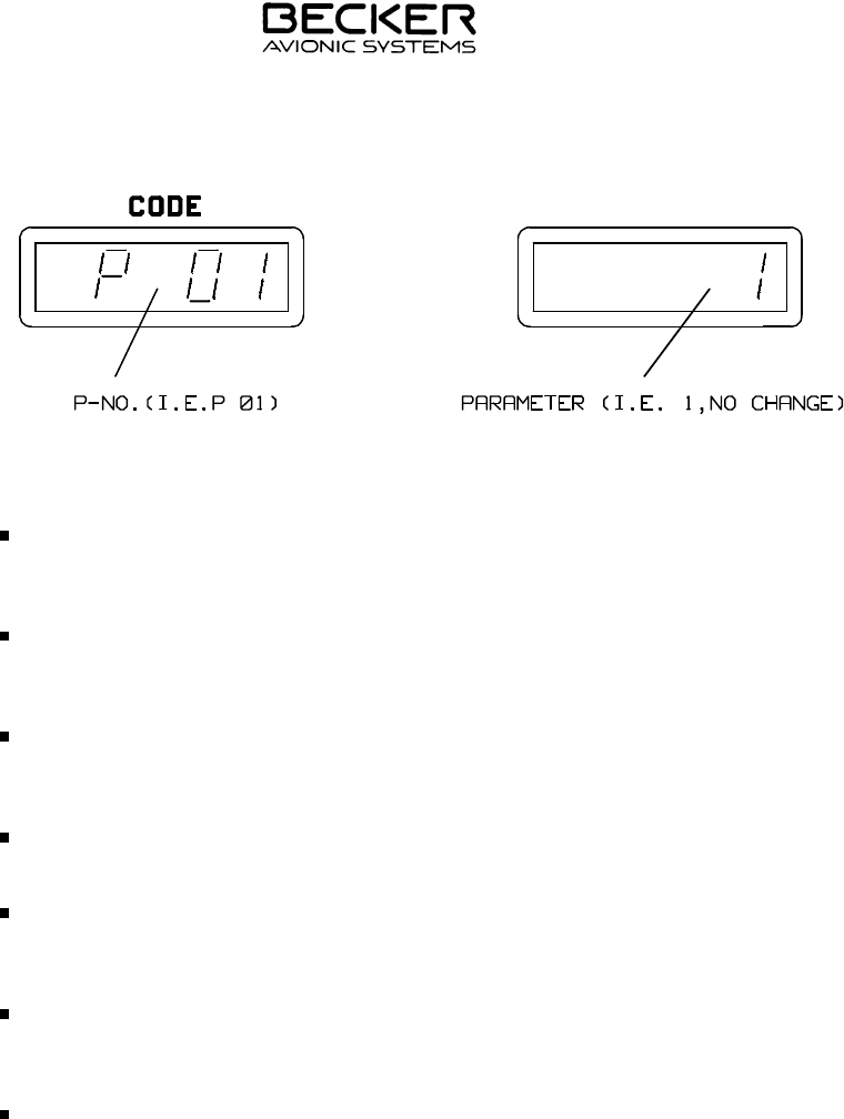
(b) The parameter number can be set in the left display using rotary
switch (B) and the parameter value in the right display using rotary
switch (C).
(c) The following settings are possible :
P number Description Parameter
(value) Procedure
P 01 Reset to factory
setting 1
2
No change
All parameters
to standard
(memory blank
= "----")
P 02 Delay time for
activation of code 2 (standard)
1 (min.)
4 (max.)
P 03 Cursor active time 3 s (standard)
1 s (min.)
5 s (max.)
P 04 Delay time for
return to previous
code
3 s (standard)
0 s (min.)
5 s (max.)
(3) The reset to the factoring setting (parameter 2) is only active if changed
not further parameters (P02 - P04) before storing.
(4) Press TEST button (K) to leave the configuration mode and store the set
values. This stores the new parameters and the transponder changes to
the mode set by mode switch (A).
(5) To leave the configuration mode without storing, set mode switch (A) to
OFF. This switches off the transponder and changes in the configuration
mode are not stored.
Example of a unit configuration :
INSTALLATION AND OPERATION
ATC 3401
Page 3-6
34-50-07 July 15/97
H. Safety
Do not connect the control unit to an a.c. voltage source of more than
32.2 V.d.c.
Do not connect the control unit to a power source with the polarities incor-
rect.
Avoid installing and using the control unit in environmental temperatures
below -20°C and over +55°C.
Switch off the unit when starting or shutting down motors or engines.
The control unit should be protected from the aircraft system by its own
1 A circuit breaker.
Do not set a code with 75XX / 76XX / 77XX. These special codes are re-
served for emergencies.
In the ON and ALT modes, the identifcation impulse is transmitted in addi-
tion to the reply code for approximately 25 seconds only in response to
Mode A requests.
INSTALLATION AND OPERATION
ATC 3401
Page 3-7
34-50-07 July 15/97

Blank
INSTALLATION AND OPERATION
ATC 3401
Page 3-8
34-50-07 July 15/97