Beckett Genisys 7505 Users Manual 61658 Control Data R08
7505 to the manual 6b128e60-f92b-448b-a674-ce4a43fdffdd
2015-01-24
: Beckett Beckett-Genisys-7505-Users-Manual-343533 beckett-genisys-7505-users-manual-343533 beckett pdf
Open the PDF directly: View PDF ![]() .
.
Page Count: 2
PARTS & ACCESSORIES
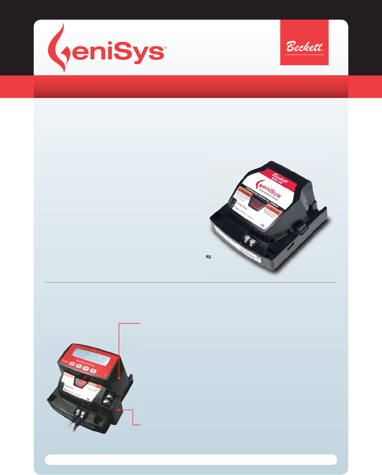
Product Description
The Beckett GeniSys™ Advanced Burner Control is a 120 Vac primary safety control for residential and light commercial oil burners used
in boiler, furnace, and water heater applications. The GeniSys is used with a suitable cad cell fl ame sensor to control the oil burner motor,
igniter, and optional solenoid valve. It has 24 Vac thermostat terminals (if applicable) compatible with both mechanical and many power
stealing thermostats. It can provide interrupted or intermittent duty ignition, and it has a 15-second lockout time.
Features & Benefi ts
Thermostat and boiler control compatible
Customizable pre-time and post-time
Three status lights for system monitoring and diagnostics
Welded relay protection with redundant motor relays
Limited reset and limited recycle
Sleek, modern design
Cad cell resistance indicator
Technician Pump Prime mode
5-Year Warranty
Two communication ports for adding alarm contacts, programming display,
and/or future wireless communications
•
•
•
•
•
•
•
•
•
•
●
7505
Advanced Burner Control
To learn more, see www.beckettcorp.com or ask for literature pt. nos. 61669 & 61687
32 character backlit alphanumeric display
Sealed pushbutton keypad
Low voltage operation
Continuous real-time cycle monitoring
Continuous cad cell resistance reading
Continuous AC line voltage read-out
Real-time error notifi cation
•
•
•
•
•
•
•
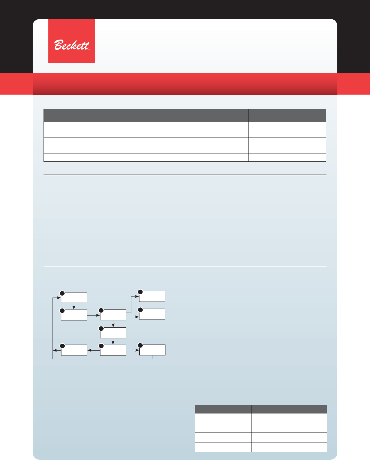
Add a GeniSys Display and GeniSys Lockout Alarm
to fully utilize the features of the GeniSys advanced burner control.
The GeniSys Display (Pt. No. 52067) allows a technician to monitor and program the
primary control variables. The display shows current burner status, control timings, and
burner cycle history. The display’s programming mode allows a technician to customize both
the pre-time and post-time settings and a lockout service message.
The GeniSys Lockout Alarm (Pt. No. 52040) functions as the interface between the primary
control and an existing alarm panel or any alarm mechanism requiring contact closure in the
event of a soft or hard lockout of the GeniSys Control.
Customizable pre-time (valve-on delay) &
post-time (motor off delay)
15 cycle history monitoring
Five Year Warranty
Customizable lockout service message
•
•
•
•
Form No. 61658 R08, Printed in the USA 04/08
PARTS & ACCESSORIES
R.W. Beckett Corporation
Mail: P.O. Box 1289, Elyria, OH 44036 ● Phone: 800-OIL-BURN (800-645-2876) ● FAX: (440)327-1064
R.W. Beckett Canada Ltd.
Unit 3 - 430 Laird Road, Guelph, Ontario, Canada N1G 3X7 ● Phone: 800-665-6972 ● FAX: (519)763-5656
www.beckettcorp.com
Priming The Pump
Initiate a call for heat.
When the burner starts, press and hold the reset button for 15
seconds until the yellow light turns on.
Release the button. The yellow light will turn off and the burner
will start again.
At burner start up, click the reset button while the igniter is still on
to enter Pump Prime mode. The yellow light will turn on.
Bleed the pump until all froth and bubbles are purged.
If necessary, repeat steps 4 and 5 until the pump is fully primed
and the oil is free of bubbles.
When fi nished, hold the reset button or remove the call for heat to
exit Pump Prime mode and return to Standby.
1.
2.
3.
4.
5.
6.
7.
Operation
Sequence of Operation
Yellow LED Flashes Cad Cell Resistance
1
Normal (0 - 400 ohms)
2
Normal (400 - 800 ohms)
3
Normal (800 - 1600 ohms)
4
Limited (1600 ohms - Lockout)
Resetting From Restricted Lockout
If the control locks out three times without a satisfi ed call for
heat or fails the motor relay check, the Lockout becomes
restricted in order to prevent repetitious resetting by the
homeowner. To reset, hold the button down for 15 seconds
until the red light turns off and the yellow LED turns on.
Disable Function
Any time the burner is running, press and hold the reset
button to disable the burner. The burner will remain off as
long as the button is held.
Cad Cell Resistance Indicator
During the burner Run state, click the reset button to check
the cad cell fl ame resistance range. The yellow light will fl ash
1 to 4 times depending on the amount of light detected by the
cad cell. See the table below:
Cross-Reference Chart
Beckett GeniSys
Control Part No. Lockout
Time Valve-on
delay time2Motor-off
delay time2Replaces
Honeywell: Replaces
Carlin:
7505A 0000 15 sec - - R7184A, R8184G 48245, 40200 42230, 502001
7505B 1500 15 sec 15 sec - R7184B -
7505P 1515 15 sec 15 sec 15 sec R7184P, R7184U1602001
7505P 1530 15 sec 15 sec 30 sec R7184P, R7184U1602001
7505P 152M 15 sec 15 sec 2 min R7184P, R7184U1602001
1) Beckett snap-in alarm module required for direct replacement of the control. 2) Valve-on delay and motor-off delay timings on all models are programmable with Beckett snap-in programming display. Other factory set
timings are available. Contact Beckett for alternate timings.
Electrical Ratings
Inputs
Voltage: 102 to 132 Vac
Current: 150 mA plus burner motor, igniter, and valve loads
Frequency: 60 Hz
Outputs
Motor:
120 Vac, 10 full load amps (FLA*), 60 locked rotor amps (LRA)
Note – Reduce motor FLA rating by igniter current
Igniter: 120 Vac, 3 A @ 0.7 PF min
Solenoid Valve: 120 Vac, 1 A @ 0.7 PF min
Thermostat Anticipator Current: 0.1 A (If applicable)
Thermostat Voltage: 24 Vac (If applicable)
Application Ratings
Oil Burner Input: < 20gph
Control Programming: UL372 Group 2
Environmental Ratings
Storage & Operating Ambient Temp.: -40°F to +150°F (-40°C to
+65°C)
Moisture: 5 to 95% RH, non-condensing and non-crystallizing
Approvals
Underwriters Laboratory Recognition per UL372 and UL1998,
and CSA
C22.2 No. 199
Standby
Motor-off
delay
Valve-on
delay Trial for
ignition
Ignition
carryover
Run
Lockout
Recycle
Pump
prime
1
234
9
7
6
5
8
