Beckman Coulter Biomedical B40421 B40421 RFID module User Manual B40420 B40421 RFID Modules
Beckman Coulter Biomedical GmbH B40421 RFID module B40420 B40421 RFID Modules
User Manual
Instructions for Use
B40420 & B40421 RFID Modules
B40420B40421
July 2015
Manufactured by
Beckman Coulter, Inc.
250 S. Kraemer Blvd.
Brea, CA 92821 U.S.A.

Instructions for Use
B40420 & B40421 RFID Modules
PN B40420B40421 (July 2015)
© 2015 Beckman Coulter, Inc.
All Rights Reserved.
Trademarks
The following Beckman Coulter trademarks are registered in the
USPTO and may be used in this manual:
• Beckman Coulter and the Beckman Coulter logo
All other trademarks are the property of their respective owners.
Find us on the World Wide Web at:
www.beckmancoulter.com
EC REP
Beckman Coulter Ireland, Inc.
Mervue Business Park, Mervue Galway, Ireland 353 91 774068
Beckman Coulter do Brasil Com e Imp de Prod de Lab Ltda
Calçada Aldebarã, 39, Centro De Apoio 2 - Alphaville,
Cep 06541-055 - Santana De Parnaíba, Sp, Brasil
CNPJ: 42.160.812/0001-44
製造販売業者: ベックマン・コールター株式会社
〒135-0063
東京都江東区有明三丁目 5 番7 号
TOC 有明ウエストタワー
贝克曼库尔特有限公司,
美国加利福尼亚州,Brea 市,S. Kraemer 大街 250 号,
邮编:92821 电话:(001) 714-993-5321
Beckman Coulter KK
贝克曼库尔特株式会社
东京都江东区有明三丁目 5 番7 号
邮编:135-0063
Original Instructions

Contents
CHAPTER 1: Important User Information, 1-1
Prologue, 1-1
Important User Information, 1-1
Declaration of Conformity, 1-1
Comprehensive Integration Instructions, 1-2
Labeling of Host Equipment, 1-2
ESD Instructions, 1-3
Product Identification, 1-3
Product Information, 1-3
Intended Use, 1-3
Unintended Use, 1-4
Product Photos, 1-4
Physical Dimensions, 1-5
Electrical Interface, 1-5
Connector Type, 1-5
Connector Pin Allocation, 1-6
Technical Specifications, 1-6
Supported TAGs, 1-7
Communication Protocol, 1-7
Timing Diagram, 1-8
Port Settings, 1-8
Commands, 1-8
Firmware Update, 1-11
Contact, 1-11
B40420B40421 iii

Contents
iv B40420B40421

CHAPTER 1
Important User Information
Prologue
These Instructions For Use must be read prior to the installation and initial start-up of the
RFID modules! It provides operating and maintenance instructions, commands, tag
references, and other detailed product information like certification and conformity.
Lire ce guide d'utilisation avant de procéder à l'installation et première mise en service du
module RFID. Il fournit des instructions d'utilisation et de maintenance, des commandes,
références de balises RFID et d'autres informations detaillées sur le produit tels que
certification et conformité.
Important User Information
IMPORTANT: Changes or modifications to this product not authorized by Beckman Coulter
Biomedical GmbH or improper use could void the Certification and negate your authority to
operate this product.
IMPORTANT: Les changements ou modifications à ce produit qui ne sont pas autorisés par
Beckman Coulter Biomedical GmbH, ainsi que la mauvaise utilisation peuvent rendre
invalide la certification et annuler votre autorisation d'opérer ce produit.
Declaration of Conformity
USA Information
The following is communications regulation information on the RFID modules Model
B40420 and B40421.
FCC ID: 2AEGN-B40420
FCC ID: 2AEGN-B40421
This device complies with 47 CFR Part 15 Rules. Operation is subject to the following two
conditions:
1. This device may not cause harmful interference.
2. This device must accept any interference received, including interference that may
cause undesired operation.
B40420B40421 1-1

Canada Information
This device complies with Industry Canada RSS-210. Operation is subject to the following
two conditions: (1) this device may not cause interference, and (2) this device must accept
any interference, including interference that may cause undesired operation of the device.
Le présent appareil est conforme aux CNR d'Industrie Canada applicables aux appareils
radio RSS-210. L'exploitation est autorisée aux deux conditions suivantes: (1) l'appareil ne
doit pas produire de brouillage, et (2) l'utilisateur de l'appareil doit accepter tout brouillage
radioélectrique subi, même si le brouillage est susceptible d'en compromettre le
fonctionnement.
IC: 20032 - B40420
IC: 20032 - B40421
Information
These devices fully comply with R&TTE Directive 1999/5/EC.
Comprehensive Integration Instructions
For proper integration of modules in the final products it is required that following detailed
and comprehensive instructions are followed by the integrators so that any subsequent
associated party (grantee, host manufacture, original equipment manufacturer (OEM),
integrator, or end-user) can clearly understand the conditions and limitations for
authorized uses of the modular transmitter:
• Do not exceed the DC power supply voltage of 5.5V.
• The power supply has to be a SELV (Safety Extra Low Voltage) type compliant to EN
60950-1.
• The DC power supply should have an output current limited to 500mA DC to avoid fire
hazard in case of a short circuit into the module or cable.
• Do not use the modules into an explosive ambient.
• Do not use any liquids or solvents to clean the modules.
• Follow the ESD instructions from this Manual.
• Do not place any electrical conductive or ferromagnetic parts into a distance of 30mm
from the PCB surface (measured perpendicular to it in both top and bottom direction)
or 10mm coplanar with the PCB from any edge of the board, in order to avoid
distorting the antenna characteristic.
• Use only the protocol and commands described in this document to control the
modules.
Labeling of Host Equipment
If the FCC / IC / CE identification number is not visible when the module is installed inside
another device, then the outside of the device into which the module is installed must also
display a label referring to the enclosed module. This exterior label should contain the
following, as applicable by model:
Important User Information
Comprehensive Integration Instructions
1-2 B40420B40421
US: Contains Transmitter Module FCC ID: 2AEGN-B40420, FCC ID: 2AEGN-B40421
Canada: Contains Transmitter Module IC: 20032-B40420, IC: 20032-B40421
Europe:
ESD Instructions
This equipment is sensitive to electrostatic discharge that can cause internal damage and
affect normal operation. Follow these guidelines when you handle this equipment:
• Touch a grounded object to discharge potential static before handling the product.
• Wear an approved grounding wrist strap or ESD clothes / shoes at a static-safe
workstation if available.
• Do not touch connectors or pins on component boards.
• Do not touch circuit components inside the equipment.
• Store the equipment in appropriate static-safe packaging when not in use.
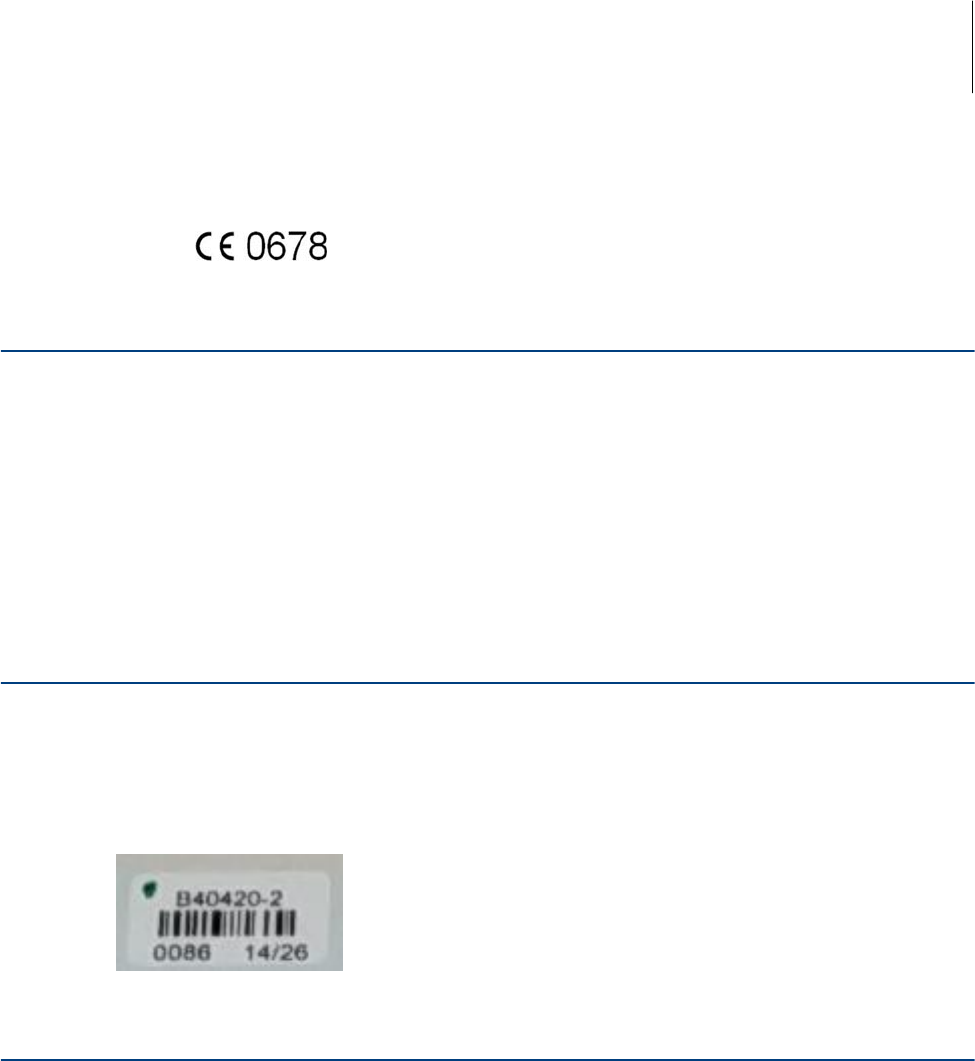
Product Identification
Model: B40420 multi antenna RFID Reader
Model: B40421 single antenna RFID Reader
Figure 1.1 Example Label
Product Information
This manual applies to B40420 and B40421 13.56 MHz RFID reader boards.
Intended Use
The modules should be used to read RFID Tags, under specific communication protocol,
power supply, and environmental conditions in industrial environment, as a part of other
equipment, machine or device. The modules are delivered without housing. Present manual
should be read and followed by technicians, engineers and manufacturing personnel
handling, building, installing, servicing or using the product. Violation of intended use may
lead to loss of compliance certification.
Important User Information
ESD Instructions 1
B40420B40421 1-3
Unintended Use
These modules are not designed and manufactured for use as standalone, or in any mobile,
consumer, automotive or outdoor application. Any product change, modification, firmware
update should only be carried out after prior approval of Beckman Coulter Biomedical
GmbH.
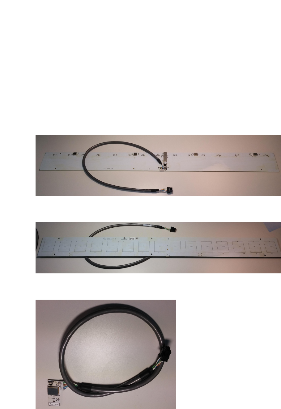
Product Photos
Figure 1.2 B40420 Top View
Figure 1.3 B40420 Bottom View
Figure 1.4 B40421 Top View
Important User Information
Product Information
1-4 B40420B40421
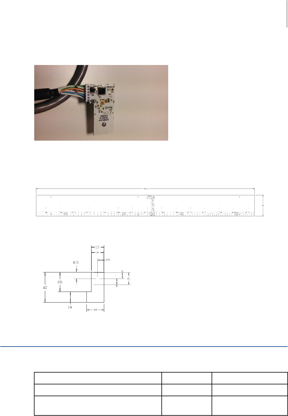
Figure 1.5 B40421 Bottom View
Physical Dimensions
Figure 1.6 B40420 PCB size: 662.5 x 63 mm, Cable length: 750 ±mm
Figure 1.7 B40421 PCB size: 23 x 40 mm, Cable length: 750 ±mm
Electrical Interface
Connector Type
Designation Manufacturer Manufacturer's part no.
RECEPTACLE, 8-POLE, MICRO-FIT 3.0 MOLEX 43025-0800
CRIMPCONTACT, FEMALE, AWG 24-20,MICRO-FIT
3.0
MOLEX 43030-0001
Important User Information
Electrical Interface 1
B40420B40421 1-5
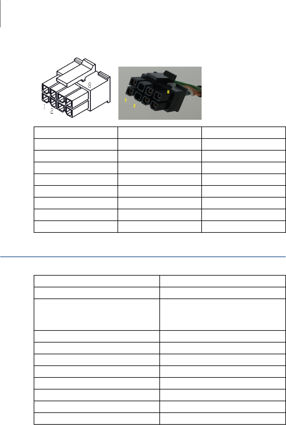
Connector Pin Allocation
Pin # Wire color Signal
1 WH/G GND
2
3 OG RX A
4 WH/BU TX Y
5 GN +5VDC
6
7 WH/OG RX B
8 BU TX Z
Technical Specifications
Model no. B40420
Item Specification
Power supply +5V ± 10%
Current consumption Standby: 32mA
Read: approx. 100mA
Communication interface 4 wire ANSI/TIA/EIA-485
Storage temperature -40°C ÷ 85°C
Operating temperature 0°C ÷ 50°C
Operating frequency 13.56 MHz
TX power Max. 200mW
Number of antennas 15, multiplexed
Type of antenna PCB integrated
Reading range 0 ÷ 30mm
Important User Information
Technical Specifications
1-6 B40420B40421

Item Specification
Supported tags ISO 15693 RFID tags
Model no. B40421
Item Specification
Power supply +5V ± 10%
Current consumption Standby: 32mA
Read: approx. 100mA
Communication interface 4 wire ANSI/TIA/EIA-485
Storage temperature -40°C ÷ 85°C
Operating temperature 0°C ÷ 50°C
Operating frequency 13.56 MHz
TX power Max. 200mW
Number of antennas 1
Type of antenna PCB integrated
Reading range 0 ÷ 10mm
Supported tags ISO 15693 RFID tags
Supported TAGs
• For B40420
Beckman order # B46145 TAG, RFID, 22mmx3mm - RCK
• For B40421
Beckman order # B41938 TAG, RFID, 10mm x 2mm - TRAN
Communication Protocol
The RFID Boards communicate using a 4 wire ANSI/TIA/EIA-485 serial communication
interface. The general structure of the communication is that the host sends a request to
the RFID Board in a defined format. The RFID board then responds to the request in a
defined time frame with a defined format. No spontaneous messages are sent by the RFID
boards. The communication protocol is compatible to the ISO/IEC 13239 Standard.
Important User Information
Supported TAGs 1
B40420B40421 1-7
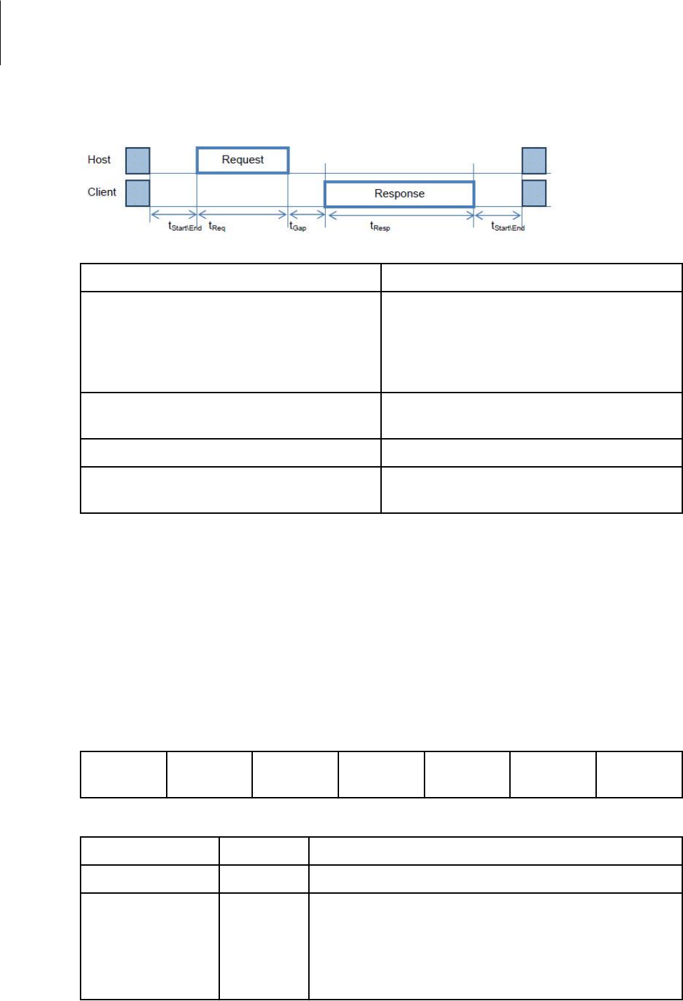
Timing Diagram
Description Symbol
Time period before start of the request telegram
or after end of a response transmission, where no
signal on the communication line is allowed. This is
defined to ensure that no collision of transmitting
happens.
tStart\End
Time period for the request telegram to be send.
Depends on the baud rate and data length.
tReq
Time period between request and response tGap
Time period of the response length. Depends on
the baud rate and data length.
tResp
Port Settings
The default setting for the serial interface is: 57.6 kbps, 8N1. These values are fixed by
firmware and cannot be changed by user. The default bus address for the RFID board is
'0x01'.
Commands
Request Format
General request format
Start Flag Address Command Parameter
Size
Parameter CRC End Flag
The definition for the fields is in the following table.
Field name Size Description
Start Flag 1 Byte Fixed value of '0x7F'.
Address 1 Byte Address of the Client that has to respond to this request.
0x01 - 0xFE : Client Address Range
0xFF: Broadcast for all connected Clients
Important User Information
Communication Protocol
1-8 B40420B40421

Field name Size Description
Command 1 Byte Command to execute from the Client. See Command
Description
Parameter Size 2 Bytes Amount of bytes used in the parameter section
Parameter n Byte(s) Parameter bytes depending on the Command
CRC 2 Bytes Checksum value CRC-16 (a.k.a. CRC-CCITT) as per definition in
ISO/IEC 13239. See [3.1.1.7] for a detailed description
End Flag 1 Byte Fixed value of '0xF7'.
Response Format
General response format
Start Flag Address Command Data Size Data CRC End Flag
The definition for the fields is in the following table.
Field name Size Description
Start Flag 1 Byte Fixed value of '0x80'.
Address 1 Byte Address of the Client that responds to the host's request.
0x00 - 0xFE : Client Address Range
Command 1 Byte Command that has been executed and that the client is
responding to
Data Size 2 Bytes Amount of bytes used in the Return section
Data n Byte(s) Data bytes depending on the Command. Contains the Return
Code.
CRC 2 Bytes Checksum value CRC-16 (a.k.a. CRC-CCITT) as per definition in
ISO/IEC 13239.
End Flag 1 Byte Fixed value of '0xF8'.
The RFID boards Serial Communication Interface supports the following (request and
response) commands:
• Initialization
—Purpose: Initialize the hardware and firmware of the client.
—Command Code: 0x01
—Format: Return Code / Board ID / Firmware Version Major / Firmware Version
Minor
—Input: NA
—Output: RFID Board ID, Firmware Version
• Set Communication Parameters
—Purpose: Sets the communication parameters for the serial communication port.
Important User Information
Communication Protocol 1
B40420B40421 1-9

—Command Code: 0x08
—Input: Bit rate, Data Bits, Parity bits, Stop bits. The Default values for the
communication parameters are 57.6 kbps, 1 start bit, 8 bits data, 1 stop bit and no
parity bit (8N1).
—Output: NA
• Start Firmware Update
—Purpose: Sets the RFID reader board to the firmware update mode.
—Command Code: 0x0A
—Input: NA
—Output: NA
• Firmware Data
—Purpose: Send the firmware data from the host to the RFID reader board.
—Command Code: 0x0B
—Input: Firmware HEX file
—Output: NA
• Set Address
—Purpose: Sets the RS-485 Bus Address for the RFID reader board.
—Command Code: 0x0F
—Input: RS-485 Bus Address
—Output: NA
• Reset Address
—Purpose: Reset the RS-485 Bus Address of the RFID reader board to the Default
value.
—Command Code: 0xFF
—Input: NA
—Output: NA
• Get antenna connection state
—Purpose: Identify the connected antennas and to know how many are connected
to the RFID Board.
—Command Code: 0x10
—Input: NA
—Output: Amount of connected antennas and Antenna indices
• Get inventory
—Purpose: Read out the inventory from all RFID tag's that are in the range of the
connected antennas.
—Command Code: 0x11
—Input: NA
—Output: Amount of connected antennas, Antenna indices, DSFID, UID
• Get memory
—Purpose: Read out the RFID Memory Data of all known RFID tag's or only one
defined RFID tag.
—Command Code: 0x1F
—Input: RFID Tag
—Output: Number of RFID Tags, Index of the antenna, Amount of data bytes for
each RFID tags and Memory data
Important User Information
Communication Protocol
1-10 B40420B40421

Firmware Update
The firmware is preprogrammed during manufacturing. The boards have both the option to
firmware update in field (in installed and powered state) during serial communication
interface, according to following procedure.
• Send / respond the following commands
— Initiation, Get Inventory for ensuring the RFID Reader Board is working fine
— Set the new baud rate (For example: 115000-8-Even-1) : 0x01
• Communication settings are changed and updated in the Application code execution
• Then send / respond the following commands
— Initiation, Get Inventory for ensuring the RFID Reader Board is working fine with
new baud rate
— Start firmware upgrade and Firmware Data - to upgrade the new firmware
command and write the new .hex file data to the flash (hex file available from
Beckman Coulter)
• Firmware upgrade command is issued firmware will jump to boot
• Boot loader will receive new firmware data with changed communication settings
• But after successful programming of new application hex file, the RFID board will
communicate with default communication settings (57600-8-None-1).
• RFID board needs power cycle after successful firmware upgrade process.
Contact
Beckman Coulter Biomedical GmbH
Sauerbruchstrasse 50
81377 Munich, Germany
Tel: +49 (0) 89 579589-0
www.beckmancoulter.com
Important User Information
Contact 1
B40420B40421 1-11

Important User Information
Contact
1-12 B40420B40421