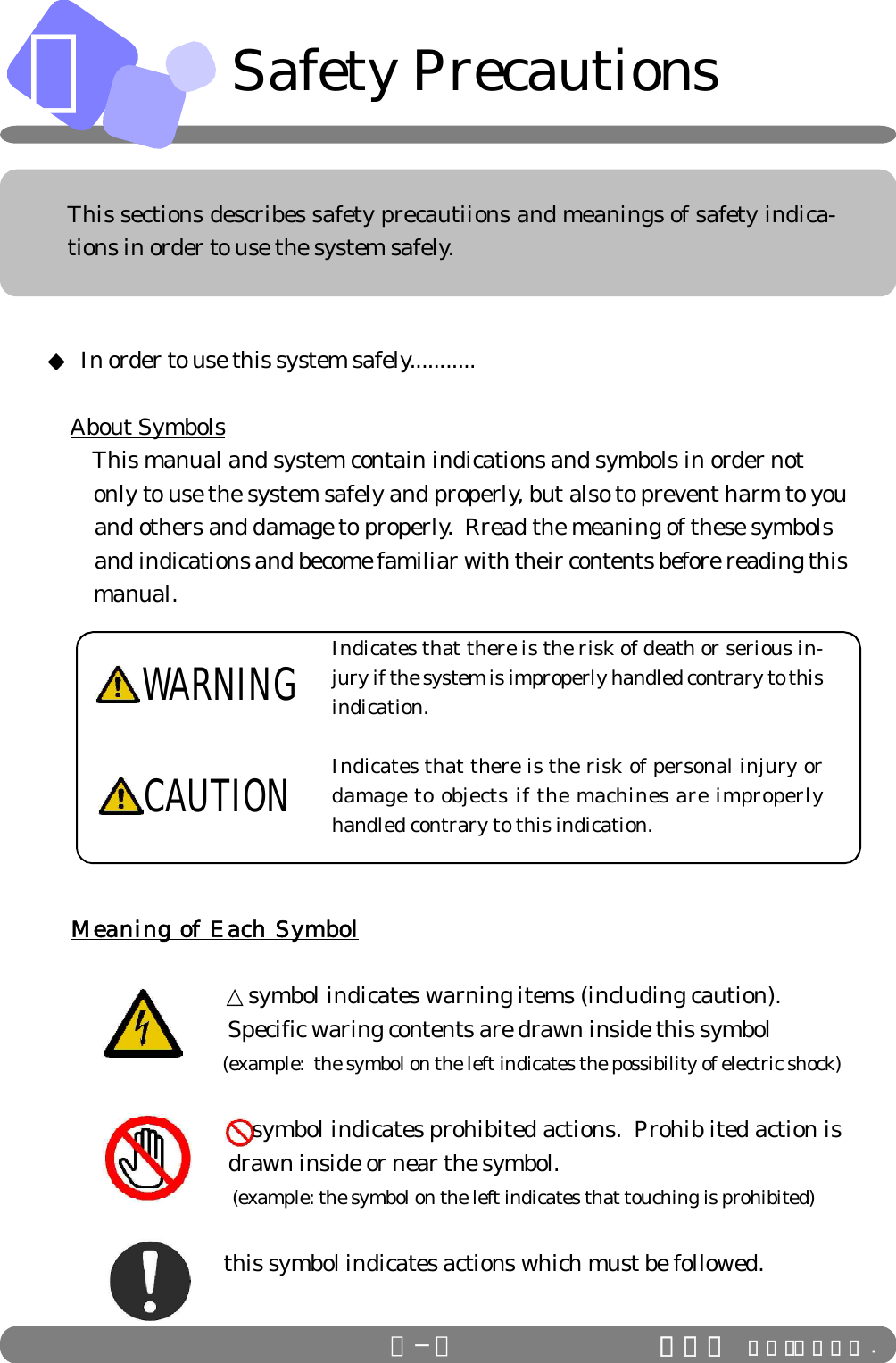
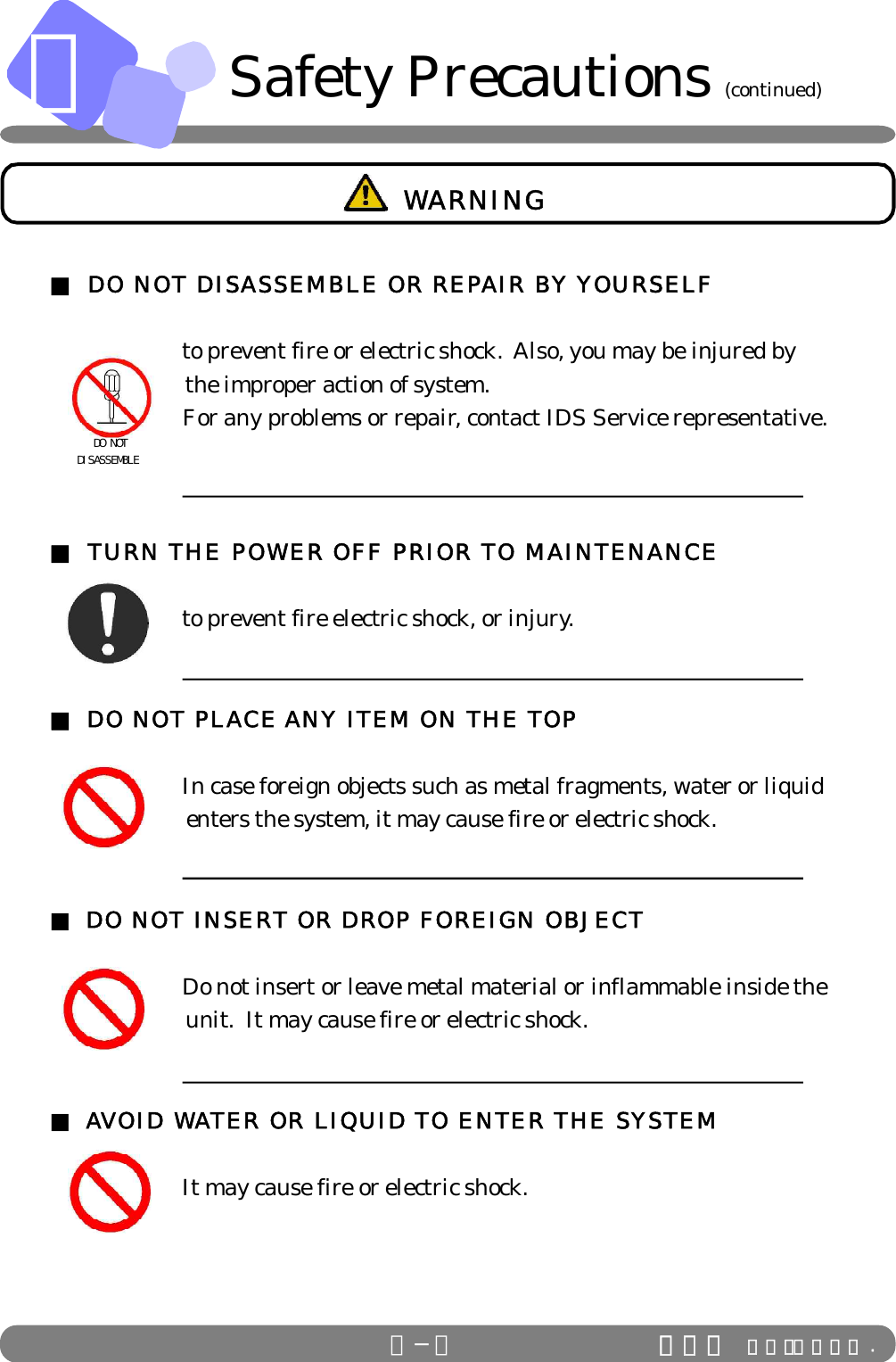
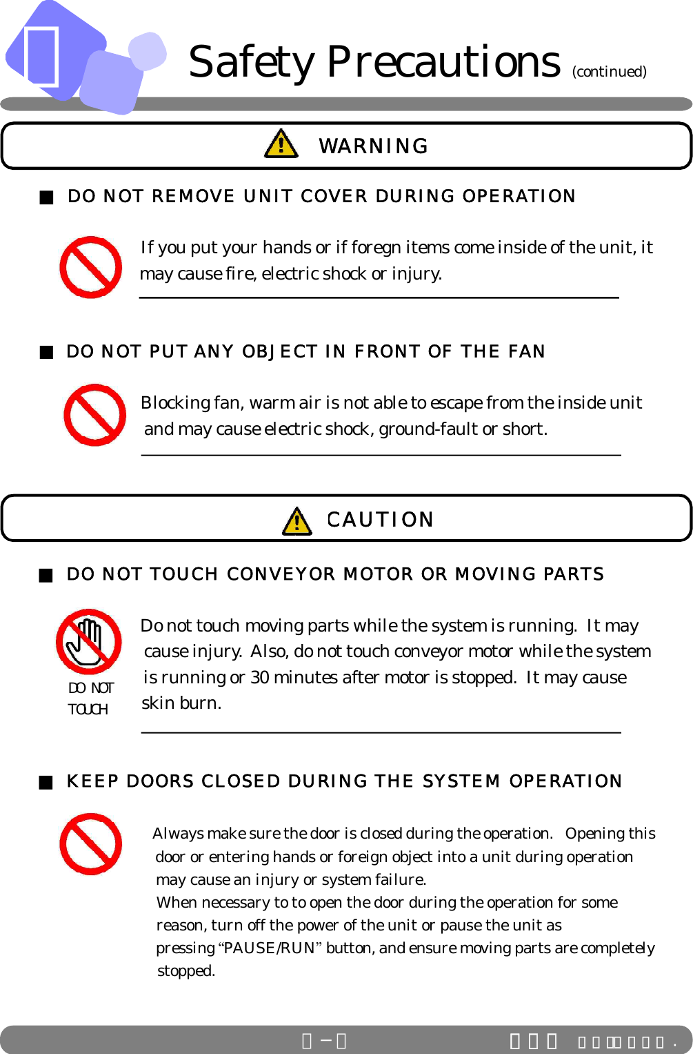
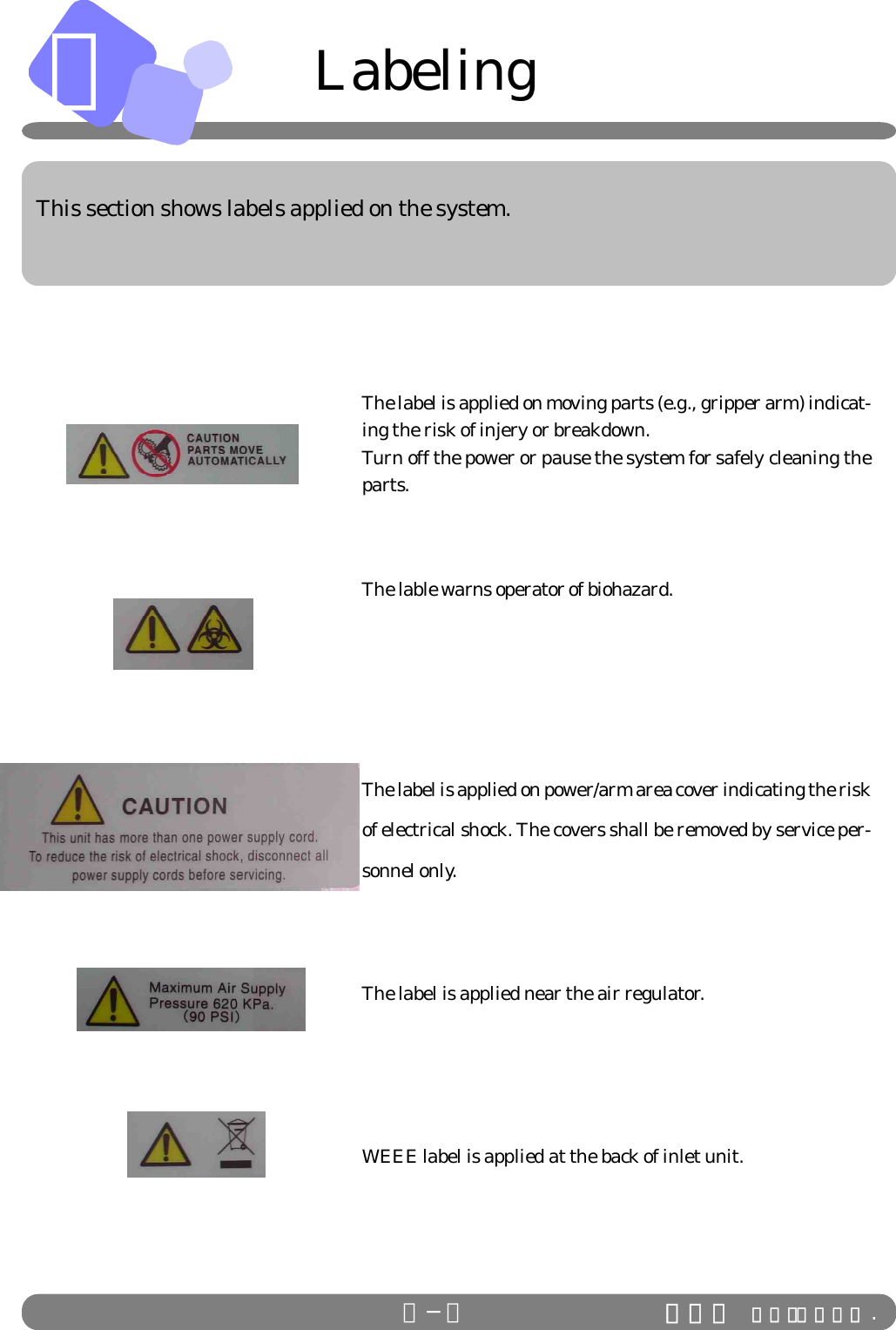
Beckman Coulter A00044109 IDS RFID Module User Manual manual

Beckman Coulter Inc., IDS RFID Module manual

manual

Stanford Hillview       IDS Co., Ltd.IDS-880Laboratory Automation SystemFirst EditionOperator’s  Manual
To our customerOur system can offer you effective space management, time saving processing power, highlyreliable parts selection and peace and quiet in your lab. Our system is designed to meet yourspecific needs.Please read this material well in order to use the system safely and properly. Also keep thishandy and with care so you can refer to more information at all times.Please note that matters described in this material can be amended without previous notice.NOTE: This equipment has been tested and found to comply with              the limits for a Class A digital device, pursuant to Part 15 of the FCC Rules.              These limits are designed to provide reasonable protection against harmful              interference when the equipment is operated in a commercial environment.              This equipment generates, uses, and can radiate radio frequency energy and,              if not installed and used in accordance with the instruction manual, may cause              harmful interference to radio communications.  Operation of this equipment in              a residential area is likely to cause harmful interference in which case the user              will be required to correct the interference at his own expense. FCC WARNING: Changes or modifications not expressly approved by the party                              responsible for compliance could void the user’s authority to operate                              the equipment.
<< Table of Contents >>A.  General Information  System Overview -------------------------------------------------------------------------- A-1 System Configuration--------------------------------------------------------------------- A-2 Safety Precautions------------------------------------------------------------------------- A-3 Labeling--------------------------------------------------------------------------------------- A-6 Marking--------------------------------------------------------------------------------------- A-7  B.    Basic Operation  Startup/Shutdown --------------------------------------------------------------------------B-1 Control Panel ------------------------------------------------------------------------------- B-2  C. Unit Function  Inlet Unit-------------------------------------------------------------------------------------- C-1 Auto Centrifuge----------------------------------------------------------------------------- C-3 Inlet Unit ------------------------------------------------------------------------------------- C-5 Recapper Unit------------------------------------------------------------------------------- C-7 Outlet------------------------------------------------------------------------------------------- C-8  D. Troubleshooting  Troubleshooting------------------------------------------------------------------------------- D-1
This section describes the explanation of general outline of IDS Labora-tory Automation System, its configuration, safety precautions, safety la-bels, and markings used throughout this manual.General InformationA
AA−1 This section describes function and features of Laboratory Automation System.System Overview◆ What does Laboratory Automation System do?   Laboratory Automation System automates sample preparation processes        based on the aliquot/sort information from the host computer and through       C-CPU (Line Control CPU) that controls each unit.        Automating routine and labor intensive tasks enhances the efficiency of        laboratory operation.◆ Key Features of IDS System Barcode Control:   All samples are managed by barcode, which                                     eliminates human error including taking a wrong          sample.    Eliminate hospital infection:  By automating sample preparation  processes, the risk of hospital infection can  be minimized.  Real-time Processing:  Single Tube Transport Method provides                                               maximum flexibility to route samples to each own        destination and accomplishes real-time processing.IDS Co.,Ltd .
A◆  The system is consisted of units as below.System ConfigurationA−2 IDS Co.,Ltd .パトライト解除1 S-3000 12 I Lane2 I Lane 13 Inlet3 S-3000 14 I Lane4 H Lane 15 Recapper5 S-3000 16 Recapper6 I Lane 17 Recapper7 S-3000 18 I Lane8 S-3000 Conn. Conveyor 19 Outlet9 Centrifuge 20 Outlet10 Inlet 21 Outlet11 I Lane1234567 8 9 1011 12 13 141516171819 20 21     This section shows configuration of the system.
AA−3 IDS Co.,Ltd .This sections describes safety precautiions and meanings of safety indica-tions in order to use the system safely.Indicates that there is the risk of death or serious in-jury if the system is improperly handled contrary to thisindication.Indicates that there is the risk of personal injury ordamage to objects if the machines are improperlyhandled contrary to this indication.◆ In order to use this system safely........... About Symbols  This manual and system contain indications and symbols in order not        only to use the system safely and properly, but also to prevent harm to you        and others and damage to properly.  Rread the meaning of these symbols         and indications and become familiar with their contents before reading this        manual.   Meaning of Each Symbol        △symbol indicates warning items (including caution).                                Specific waring contents are drawn inside this symbol                                (example:  the symbol on the left indicates the possibility of electric shock)           symbol indicates prohibited actions.  Prohib ited action is                                drawn inside or near the symbol.                                  (example: the symbol on the left indicates that touching is prohibited)        this symbol indicates actions which must be followed.WARNINGCAUTIONSafety Precautions
AA−4 IDS Co.,Ltd .■ DO NOT DISASSEMBLE OR REPAIR BY YOURSELF      to prevent fire or electric shock.  Also, you may be injured by                        the improper action of system.      For any problems or repair, contact IDS Service representative.■ TURN THE POWER OFF PRIOR TO MAINTENANCE      to prevent fire electric shock, or injury.■ DO NOT PLACE ANY ITEM ON THE TOP      In case foreign objects such as metal fragments, water or liquid                        enters the system, it may cause fire or electric shock.■ DO NOT INSERT OR DROP FOREIGN OBJECT      Do not insert or leave metal material or inflammable inside the                        unit.  It may cause fire or electric shock.■ AVOID WATER OR LIQUID TO ENTER THE SYSTEM      It may cause fire or electric shock.   DO NOTDISASSEMBLE WARNINGSafety Precautions (continued)
AA−5 IDS Co.,Ltd .■ DO NOT REMOVE UNIT COVER DURING OPERATION      If you put your hands or if foregn items come inside of the unit, it                       may cause fire, electric shock or injury.■ DO NOT PUT ANY OBJECT IN FRONT OF THE FAN            Blocking fan, warm air is not able to escape from the inside unit                        and may cause electric shock, ground-fault or short. WARNING■ DO NOT TOUCH CONVEYOR MOTOR OR MOVING PARTS      Do not touch moving parts while the system is running.  It may                        cause injury.  Also, do not touch conveyor motor while the system                        is running or 30 minutes after motor is stopped.  It may cause                        skin burn.■ KEEP DOORS CLOSED DURING THE SYSTEM OPERATION                      Always make sure the door is closed during the operation.   Opening this                            door or entering hands or foreign object into a unit during operation                            may cause an injury or system failure.         When necessary to to open the door during the operation for some                            reason, turn off the power of the unit or pause the unit as                               pressing “PAUSE/RUN” button, and ensure moving parts are completely                            stopped. DO NOT TOUCHCAUTIONSafety Precautions (continued)
A   LabelingA−6The label is applied on moving parts (e.g., gripper arm) indicat-ing the risk of injery or breakdown.Turn off the power or pause the system for safely cleaning theparts.The lable warns operator of biohazard.The label is applied on power/arm area cover indicating the riskof electrical shock. The covers shall be removed by service per-sonnel only.The label is applied near the air regulator.WEEE label is applied at the back of inlet unit.IDS Co.,Ltd .     This section shows labels applied on the system.
AA−7 IDS Co.,Ltd .MarkingsThis section shows markings used in this manual.Check Ref.NOTE! indicates that the special care is required in the process.indicates the items that need to be noted for the certainprocess or handling.indicates the page number or the name of manual that canbe used as reference and gives you the related informationor procedure in detail.
BBasic OperationThis section explains operating instructions for the control panel and  howto startup/shutdown the system.
セット清掃。のOFFBB−1How to startup system:Step 1:  Turn on air supply.Step 2:  Turn on the system power.Step 3:  Prepare the following for each unit.     Inlet/Outlet Unit for primary samples … Set empty racks.     Outlet Unit for secondary samples …Set empty racks.     Decapper Unit … Remove caps from disposal box and clean the chute.     Labeler Unit … Refill with tubes and set labels.               Aliquoter Unit … Refill with tips. Remove used aliquot tips from disposal                                           box and clean the chute.Step 4:  Turn on C-CPU power.How to shutdown system:Step 1:  Turn off C-CPU power.Step 2:  Turn system power.Step 3:  Turn off air supply.IDS Co.,Ltd .This section describes how to startup/shutdown system.  The procedures inthis page is also included in the manual for IDS-3000.    Startup/Shutdown
BB−2 IDS Co.,Ltd .Control Panel (IDS-880)This section describes how to use control panel and the functions of each but-tons.MODE CHANGE switchPAUSE / RUN button ALARM buttonENTER button Digital DisplayControl PanelLEDLED LED LEDFUNCTION button◆ General outline of each mode 1) Operation  Mode   There are two modes for operation mode; Auto Mode and Manual Mode.  By pressing          AUTO/MANU button twice, the mode can be switched back and forth between the two modes.     >  AUTO MODEThis mode is to make each unit be in operation, and process samplesautomatically when they arrive on the system or each unit. >  MANUAL MODE/MAINTENANCE MODEThis mode is to make each unit in halt condition.  When this mode is selected,                                “00” is displayed on the LED display.  To select MAINTENANCE mode, press                                FUNCTION button while the system is in MANUAL mode.  By pressing ENTER button, the maintenance mode is executed.  To switch to Auto Mode, press AUTO/MANU button twice.         To use MANUAL (MAINTENANCE) MODE, call IDS Service representative                              for the procedure.              In the case the operation mode is switched during a process, it will be switched                                  over after completing the process being in action.  The LED keeps flashing                                  during this process of mode change.  By pressing AUTO/MANU button for or                                  more than 3 seconds, the mode is forcefully switched over.     CheckNOTE!WARNING LEDRACK CHANGE LEDRACK LOAD buttonLEDPRIORITY buttonLEDENTERAUTOMANUAL RUNALARMPAUSEFUNCTIONRACKLOADPRIORITY
BB−3 IDS Co.,Ltd .Control Panel (IDS-880)           (continued)2)  PAUSE/RUNBy pressing PAUSE / RUN button, the system is suspended.  To resume operation, pressPAUSE / RUN button again.3)  ALARMWhen an error occurs during the operation, the system pauses operation, ALARM            LED start flashing and error code is displayed on the digital screen.  By pressing FUNCTION button, the location of error (i.e., sensor or cylinder number) is displayed on the screen.  To stop the alarm, press ALARM button.  Refer to Error Code List and recover from            the error.  Press PAUSE/RUN button to resume operation and yellow LED turns off.     ◆ Functions of each button and indications by LED1) AUTO/MANUAL buttonTo switch operation mode, press AUTO/MANUAL button to select the mode.  The LED     blinks for 5 seconds.  By pressing the button while LED is flashing, operation mode switches to           the other mode.   When power is turned on, the mode is automatically set AUTO.      If mode is switched in the process of operation, it will be switched after completing it.◎AUTO mode/ LED Display>  Sample are processed automatically.>  LED of AUTO mode turns on.>  If AUTO/MANU button is pressed while the LED of AUTO mode is on, the              LED flashes for 5 seconds.◎MANUAL mode/ LED Display>  Samples are not processed automatically, and the unit is disconnected from the system.>  LED of MANUAL mode turns on.>  If AUTO/MANU button is pressed while the LED of MANUAL is on, the              LED flashes for 5 seconds.2) PAUSE/RUN button◎When pressed in the process of operation,>  Unit will pause operation once the process is completed, and will not start the next                   process.◎When pressed while unit is paused/ LED Display>  Resume opearation.Check
BB−4 IDS Co.,Ltd .< Sound Patter of Auditable Alarm >(Sound Pattern) (Condition)Continuous sound Error occurredDiscontinuous sound Error occurred in sample order monitoring.  3) ALARM buttonPress ALARM button and the audible alarm stops.   ◎ ALARM button  and WARNING  LED      >  LED on ALARM button flashes with alarm sound.>  Press ALARM button, the alarm stops and LED stops flashing.>  Press PAUSE/RUN button to resume the operation, the LED turns off.> Turn on/off of ALARM LED and WARNING LED are synchronized.      4) ENTER button   ◎ Pressed while the system is in MANUAL mode>  Execute the maintenance mode selected.   ◎ Pressed while the system is in MAINTENANCE mode     >  Complete the ongoing process, switche operation mode to AUTO.5) RACK LOAD button   This  button allows rack change before rack becomes full or empty>  Press RACK LOAD button, rack can be changed after the robotic arm completes                       the operation in process. LED of RACK LOAD stops flashing when the arm com                       plete the operation.      >  When LED of RACK LOAD is turned on after the arm completes the pro                         cesses, stop the auditable alarm and change the rack.     >  Press PAUSE / RUN button and resume the operation.6) PRIORITY button   Press PRIOTIRY button and unit start or continue process without waiting for the          predetermined number of samples or carriers at  a certain position, or waiting predeter         mined time period.Control Panel (IDS-880)           (continued)
BB−5 IDS Co.,Ltd .7) FUNCTION (+/-) button         The button changes error displays on the panel indicating error type and location.            See the TABLE 1 below for the descriptions       + By pressing (+) switch, error type is displayed on the panel   and error location is displayed by pressing (-).+ When multiple errors occurs, errors are displayed in the order of   their occurrence. After clearing an error, the next error will be dis    played.   (TABLE 1)CheckControl Panel (IDS-880)           (continued)Error Type  Error Location  Description 0  01 - 99  Barcode read error at position 01-99 1  01 - 99  Error at SN01-99, SN: Sensor 2  01 - 99  Error at SL01-99, SL: Cylinder 3  01 - 99  Error at BR01-99, BR: Barcode Reader 4  01 - 99  Error at PM01-99, PM: Pulse Motor 5  01 - 99  Connection error with Analyzer 7  01 - 99  Error at AS01-99, AS: Auto Switch 9  01 - 99  Other errors
B−6 IDS Co.,Ltd .BB−6     >>  Lane Through   This function is used when a holder needs to be forced to the next unit.   < Procedure>(1)  Change operation mode of the unit to MANUAL (Maintenance.)(2)   Set ・1・using + or - of FUNCTION button, and press ENTER button.(3)  To exit the lane through function, change the operation mode to                          AUTO.         Lane Through function can also be set at C-CPU.Only from C-CPU, all the units can go into Lane Through.>>  Forced pass for the sample in case of barcode read error             (Error Type 0)      This function is used to pass sample tubes (or holder) with barcode read error.      When barcode read error occurs, error type “0” is displayed on the panel. < Procedure>      (1)  Press ALARM button to stop the audible alarm.(2)  Press PAUSE/RUN button with ENTER to move the error sample out of                         barcode reader.>> Emmergency Stop Switch                    If this is pressed in emergency, system power shuts off.IDS Co.,Ltd .CheckControl Panel (IDS-880)           (continued)
CUnit FunctionThis section explains functions and features of each unit.
C      Inlet Unit◆Inlet Unit    The inlet arm automatically loads a sample into sample carrier    on lane. When barcode read error occurs, no sample programming     is available or sample barcode is duplicate,the sample tubes  sort to     error rack marked  4 in the previous page. When they are sorted to     the error rack, audible alarm warns operator.◆Changing Racks ・Before rack becomes full,      1. When inlet trays (see the next page) becomes empty, buzzer sounds to notify operator.       2. Press ALARM button to stop buzzer sound. If the button is not pressed for 5 seconds, the buzzer stops         automatically.      3. After confirming that the arm is paused, change the racks. When trays with samples are loaded,         PUAUSE/RUN LED starts flashing.      4. Press PAUSE/RUN to resume operation.C−1 IDS Co.,Ltd .ENTERAUTOMANUAL RUNALARMPAUSEFUNCTIONRACKLOADPRIORITYControl Panel
C  Inlet Unit  (continued)                      IDS Co.,Ltd ◆Changing Racks ・Before rack becomes full,        1. Press RACK LOAD button, the robotic arm pauses operation and buzzer           sounds.      2. Press ALARM button to stop the buzzer sound.        3. Unload the rack to be changed.        4. Load empty tray on the rack set position.        5. PAUSE/RUN LED starts flashing. Press PAUSE/RUN button.        6. After changing the rack, reume the operation.◆ Manual Load of a Sample Tube   1. Press PAUSE/RUN button and confirm that the robotic arm puased operation.        2. Set a sample tube into the empty holder at the loading position.        3. Press PAUSE/RUN button and the sample in the holder will  be released from the position.       Manually loaded tube as above procedures is prioritized over tubes in rack.◆Rack TypeRack Number◆①②③④Tubes to Tubes to Tubes to Errorbe loaded be loaded be loaded Samples① ② ③Sample Tube Position◆1 2 3 4 5The position of rack is assigned from the left tothe right and front to the back.49 50C−2 IDS Co.,Ltd .
CAuto Centrifuge◆ Centrifuge:         automatically loads sample tubes set in sample         rack into the centrifuge rotor and unload to         the lane after centrifugation.◆ Operationg condition:        When five sample tubes arrived on the lane, centrifuge        arm starts loading samles into the unit. (Centrifuge arm        starts loading after predetermined timeout even when        there are less than 5 sample tubes on the convyeor. Also,        if PRIORITY is pressed, centrifuge arm starts loading.)◆ How to change the setup at the control panel on unit     side:    Changing timeout:      (centrifugation with less than 40 sample tubes.)         1. While in MANUAL (Maintenance) mode, set “82”             and press ENTER.        2. Press FUNCTION and enter a number, which will be set as timeout             (i.e., period after the first sample arrives at centrifuge and wait for the           next tube.)U n i tU n i tTIM ER FUNCTIONSPE ED×100 rpm ×10 SEC.C o n t r o lENTERAUTOMANUAL RUNALARMPAUSEFUNCTIONRACKLOADPRIORITYENTERAUTOMANUAL RUNALARMPAUSEFUNCTIONRACKLOADPRIORITY        Note!   The display shows 1/10 of the time.C−3 IDS Co.,Ltd .
C             Changing spin time:   1. While in MANUAL (Maintenance mode), select  “81” and press ENTER.   2. Enter time using FUNCTION, press ENTER.      Note!   The display shows 1/10 of the time in seconds. Changing spin speed:     Turn the volume clockwise for faster speed, and turn it counterclockwise for     lower speed.      Note!    The display shows the current speed during spin                     (1/100 in seconds.) ◆ Opening the centrifuge lid:     Turn “Releae Door Lock” switch to unlock and open the lid. ◆ Error display:  ・ Errors on unit and conveyor sides are displayed on each control paenel.    (i.e., error specific to centrifuge unit will be displayed on the panel of           unit side, while lane related error will be displayed on the panel of           conveyor side.)  ・ If the error is related to both, it will be displayed on both of the panels.For basic panel operation, refer to  B in this document.C−4 IDS Co.,Ltd .        Auto Centrifuge (continued)Ref.
C      Inlet Unit◆Inlet Unit    The inlet arm automatically loads a sample into sample carrier    on lane. When barcode read error occurs, no sample programming     is available or sample barcode is duplicate,the sample tubes  sort to     error rack marked  4 in the previous page. When they are sorted to     the error rack, audible alarm warns operator.◆Changing Racks ・Before rack becomes full,      1. When inlet trays (see the next page) becomes empty, buzzer sounds to notify operator.       2. Press ALARM button to stop buzzer sound. If the button is not pressed for 5 seconds, the buzzer stops         automatically.      3. After confirming that the arm is paused, change the racks. When trays with samples are loaded,         PUAUSE/RUN LED starts flashing.      4. Press PAUSE/RUN to resume operation.C−5 IDS Co.,Ltd .ENTERAUTOMANUAL RUNALARMPAUSEFUNCTIONRACKLOADPRIORITYControl Panel
C  Inlet Unit  (continued)                      IDS Co.,Ltd ◆Changing Racks ・Before rack becomes full,        1. Press RACK LOAD button, the robotic arm pauses operation and buzzer           sounds.      2. Press ALARM button to stop the buzzer sound.        3. Unload the rack to be changed.        4. Load empty tray on the rack set position.        5. PAUSE/RUN LED starts flashing. Press PAUSE/RUN button.        6. After changing the rack, reume the operation.◆ Manual Load of a Sample Tube   1. Press PAUSE/RUN button and confirm that the robotic arm puased operation.        2. Set a sample tube into the empty holder at the loading position.        3. Press PAUSE/RUN button and the sample in the holder will  be released from the position.       Manually loaded tube as above procedures is prioritized over tubes in rack.◆Rack TypeRack Number◆①②③④Tubes to Tubes to Tubes to Errorbe loaded be loaded be loaded Samples①②③Sample Tube Position◆1 2 3 4 5The position of rack is assigned from the left tothe right and front to the back.49 50C−6 IDS Co.,Ltd .
CC−7  Recapper Unit◆ Recaper Unit  The unit put caps on sample tubes to prevent evapolation       of sample.◆Opening the door     1. Press DOOR button and LED of the button turns off.         LED of PAUSE/RUN button turns on indicating the unit in puase and         operator can open the door.     2. When the door is closed, LED of DOOR button turns on and automatically         lock the door.     3. Press PAUSE/RUN button to resume operation.     Note: Rear interlock cover is unlocked at the button located on the rear              side. ALARM and PAUSE button on the rear side can also be used.◆Supplying caps   1. Alarm sounds when caps in the feeder requires refill.   2. Press ALARM button and refill caps in the feeder.   3. Press PAUSE/RUN to resume operation.    Too many caps in the feeder may cause errors. Caps failed to be put on tubes               shall be cleaned regularly.               Alarm sounds when cap disposl box becomes full. Press ALARM button and               discard caps.   Note!IDS Co.,Ltd .ENTERAUTOMANUAL RUNALARMPAUSEFUNCTIONRACKLOADPRIORITYControl Panel
C◆Outlet Unit  The robotic armunloads coagulation and hematology    samples into rack. Information of the samples unloaded at    Outlet unit can be checked at C-CPU.◆Changing Racks ・When rack becomes full,  1. The robotic arm stops operation, buzzer sounds to notify operator.  2. Press ALARM button to stop the buzzer.      3. Rack number that became full is displayed on the panel. Unload the rack.        4. Load empty tray on the rack set position.        5. After PAUSE/RUN LED starts flashing, press PAUSE/RUN button to           re sume  operation.  C−8 IDS Co.,Ltd .ENTERAUTOMANUAL RUNALARMPAUSEFUNCTIONRACKLOADControl Panel         Outlet Unit
C  ◆Changing Racks ・Before rack becomes full,        1.  Press RACK LOAD button, the robotic arm pauses operation and buzzer            sounds.      2.  Press ALARM button to stop the buzzer sound.        3.  Unload the rack to be changed.        4.  Load empty tray on the rack set position.        5.  PAUSE/RUN LED starts flashing. Press PAUSE/RUN button.        6.  After changing the rack, reume the operation.◆Rack Type     Warning:  Do not touch the rack area or change rack while the robotic arm is                         in operation.  Outlet Unit (continued)C−9 IDS Co.,Ltd .Sample Tube Position◆1 2 3 4 5The position is assigned from the left to the rightand front to the back.49 50Rack Number◆① ③ ⑤ ⑦② ④ ⑥ ⑧
TroubleshootingDThis section covers troubleshooting
DD−1  IDS Co.,Ltd .NOTE!              Adjustment or replacement of parts shall be performed by autorized              engineers.TroubleshootingProblem CountermeasureError occurred on theentire system at power-on. Turn on the power of compressor."SL" errors occurredthroughout the system. Open the air valve.There is an obstructionwithin the operating rangeof the cylinder.Remove the obstruction.Check the air pressure.Adjust the speed controller.The cylinder got damaged. Replace the cylinder.Replace the solenoid valve.Replace the air duct.There is a break in a autoswitch cable. Replace the cable.A connector pin is notconnected. Connect the connector pin.The auto-switch is not atthe proper position. Adjust the position of auto-switch.Clean the pulley.Replace the bearing.Replace the motor.Replace the belt.Replace the timing belt.Connect the connector pin.Replace the fuse.Replace the barcode reader.Clean LED area of barcode reader.Replace or adjust the sensitivity ofamplifier.Clean the fiber head.Replace the sensor.Replace the motor.Replace the cable.Replace the fuse.Connect the connector pin.Tighten the screw.Grease driving part.Replace the printer head.Poor print quality (too light) Clean the printer headSample tubes can not berouted to analyzer. Interface setting at the C-CPU is off. Turn on the CPU interface setting.CauseThe compressor is not powered on.The air valve for the compressor or air tank is notopened.Cylinder is notfunctioning properly.Cylinder errorPulley is covered with dust.Bearing is damaged.Motor is damaged.Conveyor does not moveor move smoothly.Malfunction of solenoid valve.Auto-switch is notreacting properly.The movement of cylinderis too slow.Air duct is damaged.Belt is damaged.Chain is damaged.Connector pin is not connected.Fuse of the control board blew out.Fuse blew out.Malfunction of barcode reader.LED area is not clean.Sensitivity of fiber amplifier is not appropriate.fiber head is not clean.Barcode reader does notread bar-code.A unit does not workproperly.Bar-coder printer does notwork properly.Connector pin came off.Screw is loose.Lack of grease.Printer head is damaged.Proximity sensor is damaged.Motor is damaged.There is a break in a cable.

Navigation menu