Beijing GODA Instruments GDRD5X6XC Pulse Radar Level Instrument User Manual FCC version12 02
Beijing GODA Instruments Co., LTD. Pulse Radar Level Instrument FCC version12 02
Users Manual
Beijing GODA Instruments Co.,Ltd.
北京古大仪表有限公司
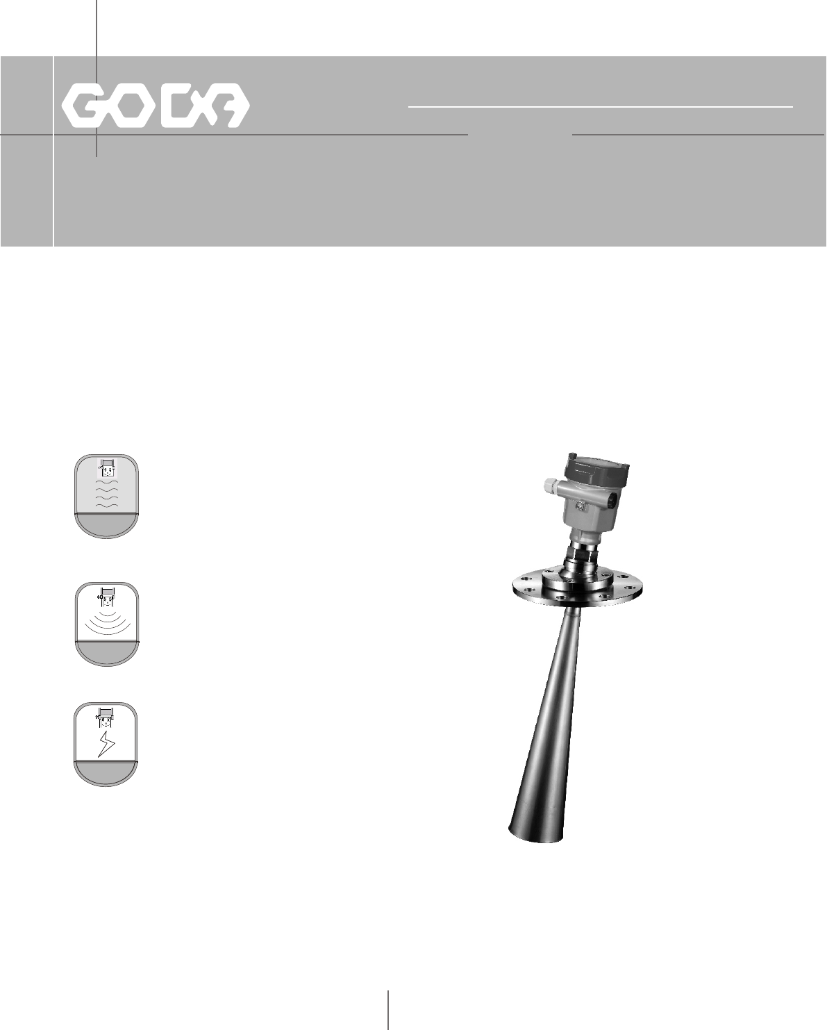
Pulse Radar Level Instrument
Level Measurement Expert

Table of Contents
1 For your safety...... ............... ....1
2 Measurement Principle ................ ...2
3 Product Overview.................... ....3
4 Mounting Requirement................. ...7
5 Electrical Connection.................. ...13
6 Adjustment Instructions................. ..15
7 Dimensional Drawings.................. ..18
8 Technical Specifications...................22
9 Selection & Ordering Information............27
10 Application Questionnaire ............ ...33

1
1.For your safety
All operations described in this operating instructions manual must be carried out ouly by trained
specialist personnel authorised by the plant operator.
During work on and with the device the required personal protective equipment must always be
worn.
Operational reliability is ensured only if the instrument is properly used according to the
specifications in the operating instructions manual as well as possible supplementary instructions.
This device complied with Part 15 of the FCC Rules. Operation is subject to the following
two conditions:
(1)this device may not cause harmful interference, and
(2)this device must accept any interference received, including interference that may
cause undesired operation.
Changes or modifications not expressly approved by the manufacturer could void the user's
authority to operate the equipment.
Authorised personal
Appropriate use
FCC Certification
Warning: User must keep a safety distance of at least 20cm from the antenna.
NOTE: This equipment has been tested and found to comply with the limits for a Class B digital
device, pursuant to Part 15 of the FCC Rules. These limits are designed to provide reasonable
protection against harmful interference in a residential installation. This equipment generates,
uses and can radiate radio frequency energy and, if not installed and used in accordance with the
instructions, may cause harmful interference to radio communications. However, there is no
guarantee that interference will not occur in a particular installation. If this equipment does cause
harmful interference to radio or television reception, which can be determined by turning the
equipment off and on, the user is encouraged to try to correct the interference by one or more of
the following measures:
-- Reorient or relocate the receiving antenna.
-- Increase the separation between the equipment and receiver.
-- Connect the equipment into an outlet on a circuit different
from that to which the receiver is connected.
-- Consult the dealer or an experienced radio/TV technician for
help.
2.Measurement Principle
The extremely narrow microwave pulse emitted by the antenna on radar level instrument
can travel at the speed of light and part of its energy, which is reflected off the surface of
target medium, is received by the very same antenna. The time lapse between pulse emission
and reception by the antenna is proportional to the distance between the surface of target
medium and the reference point on antenna. However, due to the fact that the electromagnetic
wave is transmitted at extremely high speed, which leads to the tiny time lapse (nanosecond
level) and makes it difficult to be identified, GDRD series of radar level instrument have
adopted a special demodulation technology, enabling itself to detect the time lapse between
pulse emission and reception correctly, and eventually generate accurate measurement result.
Principle
The pulse radar level instrument, adopted K band range as transmission frequency, which
make this series have specialties as below: Small beam angle, which centralize energy, make
GDRD high ability of anti-jamming, hence high accuracy and reliable. Small antenna size,
easy to mount and easy to equip extra dust protection. Small blind zone, good accuracy
ev en fo r s ma ll ve ss e ls . S ho rt er wa ve - le ng t h, su it ab le fo r s ma ll po we r.
Equipped with advanced microprocessor and unique EchoDiscovery echo processing
technology, the radar level instrument can be used under various hazardous process conditions
The pulse radar level instrument, with pulses as its working tool and extremely low
emission power, can be mounted on various metal or nonmetal vessels, harmless towards
the environment and human beings.
Features
2
3 Product Overview
Max Measurement Range::
Measurement Accuracy:
Process Temperature:
Process Pressure:
Signal Output:
Power:
Display module:
Housing:
Process Connection:
Flange Accessories:
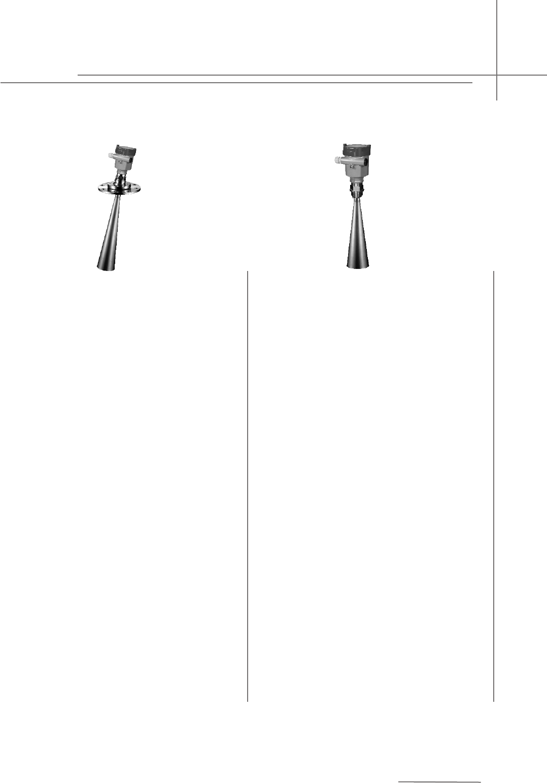
Antenna:
Application:Liquid
Level measurement in liquids,
especially highly erosive liquids
10m
±5mm
o
(-40~130) C
(-0.1~0.3)MPa
(4~20)mA/HART
2-wire(DC24V)
A
F
L
R
GDRD55
GDRD61
Liquid
Common 30m Enhanced 70m
±3mm ±10mm
o
(-40~100) C
Ordinary pressure
(4~20)mA/HART
2-wire(DC24V)
None
Pa66
Lifting frame or 1’NPT
3
GDRD56
Liquid
Level measurement in liquids, under certain
temperature and pressure, mildly erosive liquids
30m
±3mm
o
(-40~80) C
o
(-40~130) C
o
(-60~250) C
o
(-60~400) C
Normal
(-0.1~4)MPa
(-0.1~40)MPa
(4~20)mA/HART
2-wire(DC24V)
Optional
A
H/I/J/K
L/M/P
T/V
GDRD57
Liquid
Level measurement of highly erosive
medium under certain pressure/
temperature limit and suitable for
20m
±3mm
o
(-40~150) C
(-0.1~0.5)MPa
(4~20)mA/HART
2-wire(DC24V)
Optional
A
U
4
GDRD58
Solid
strong dew/dust/crystal
70m
±15mm
o
(-40~80) C
o
(-40~120) C
o
(-60~250) C
o
(-60~400) C
Normal
(-0.1~4)MPa
(-0.1~40)MPa
(4~20)mA/HART
2-wire(DC24V)
Optional
A
H/I/J/K
L/M/P
T/V
GDRD59
Solid
Normal Temperature/Normal Pressure
15m
±10mm
o
(-40~80) C
Normal
(4~20)mA/HART
2-wire(DC24V)
Optional
A
G
L/M/N
T
5
Pulse Radar Level Instrument
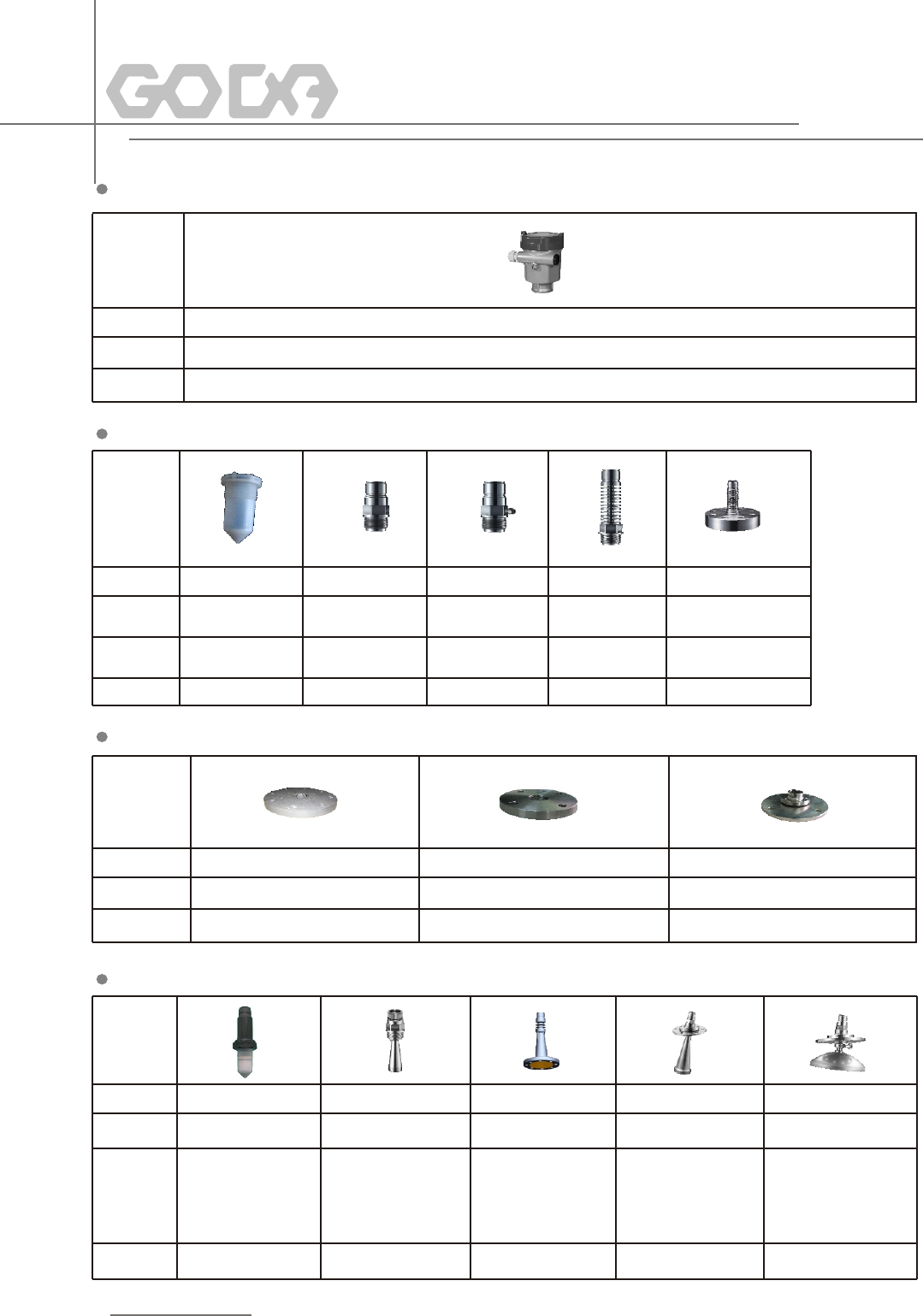
Serial number
Material
Specialty
Serial number F H I J K
Material PFA Stainless Steel Stainless Steel\\ Stainless Steel Stainless Steel Flange
(Huff)
Serial number L M P
Material (PTFE/PP)Flange Stainless Steel Flange Stainless Steel Gimbal Flange
Specialty Rust tolerated High temp./High Pressure High temp./Normal Pressure
Serial number R T U V W
Material Stainless steel PFA Stainless steel(PFA
shield)
Specification Φ44/Length86 Φ48/Length140 Φ98/300
Φ44/Length108 Φ78/Length227 Dn80 Φ123/625
Φ98/Length288 DN100
Φ123/Length620
Housing
Process Connection
Flange Accessories
Antenna
Pressure (-0.1~0.3)MPa (-0.1~4)MPa (-0.1~0.5)MPa (-0.1~4)MPa (-0.1~40)MPa
o o o o o
Temperature (-40~130)C (-60~150)C (-60~130)C (-60~250)C (-60~400)C
Specialty Normal Temperature Temperature tolerated/ Rust tolerated/ Normal Temperature/ Temperature tolerated/
Pressure tolerated Pressure tolerated Normal Pressure Pressure tolerated
6
A
Aluminium
Stainless steel
Φ198
Φ246
4.Mounting Requirements
Basic Requirements
7
>200mm
11
2
11111111
2222
33
3
33
100%
0%
4
There is a certain existing beam angle while the antenna transmitting microwave pulses. There should be no barriers
between the lower edge of antenna and surface of measured medium. Therefore it is highly recommended to avoid
facilities inside vessels, such asladders, limit switches, heating spirals, struts and etc, during the mounting process.
“False echo learning” must be carried out during the installation in this case. Furthermore, microwave beams must
NOT intersect the filling streams. Be cautions during the installation: the highest level of target medium must NOT
enter into blanking zone; the instrument must keep certain distance to vessel walls; every possible measure needs
to be taken to position the instrument so that the direction of antenna emission is perpendicular to the surface of
measured medium. The installation of instruments in explosion proof area must abide by relevant local or federal
safety regulations. Stainless steel housing should be used for intrinsically safe explosion proof version, which is also
applicable in explosion proof areas. The instrument must be connected with ground in this case.
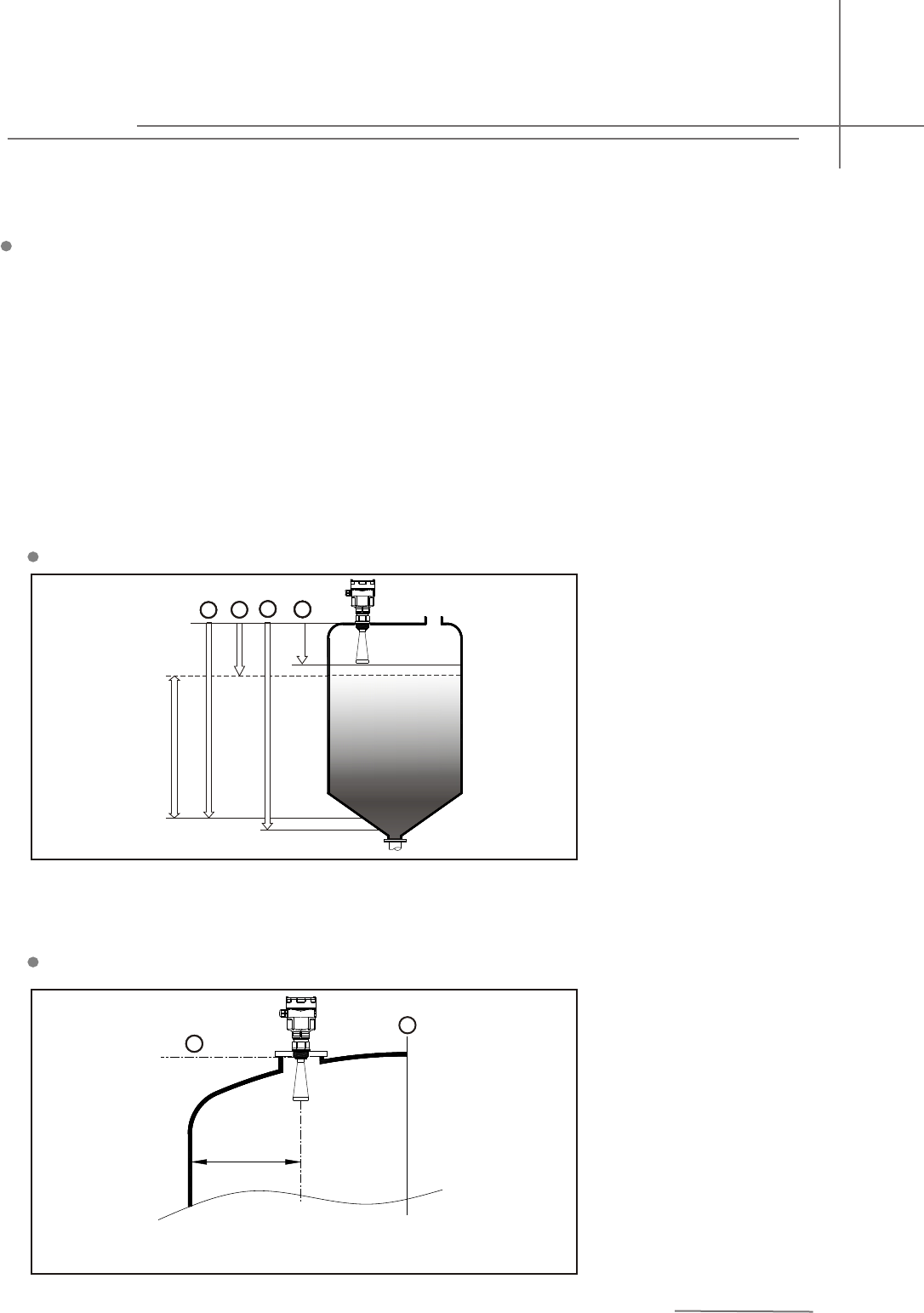
Illustrations
1.Reference Plane
2.Center of Vessel or Symmetrical
Axis
Minium distance of 500mm
between instrument and vessel
wall during installation
The reference plane is the
thread or flange surface
1. Blanking Zone(menu1.9)
2. Empty(menu1.8)
3. Max. Adjustment(menu1.2)
4. Min. Adjustment(menu1.1)
Note:The highest level of measured medium must not enter into vlanking zone while
radar level measurement instrument is in operation.
Mounting Position
Pulse Radar Level Instrument
>200mm
1
2
R
2
1R
Installation with Gimbal
8
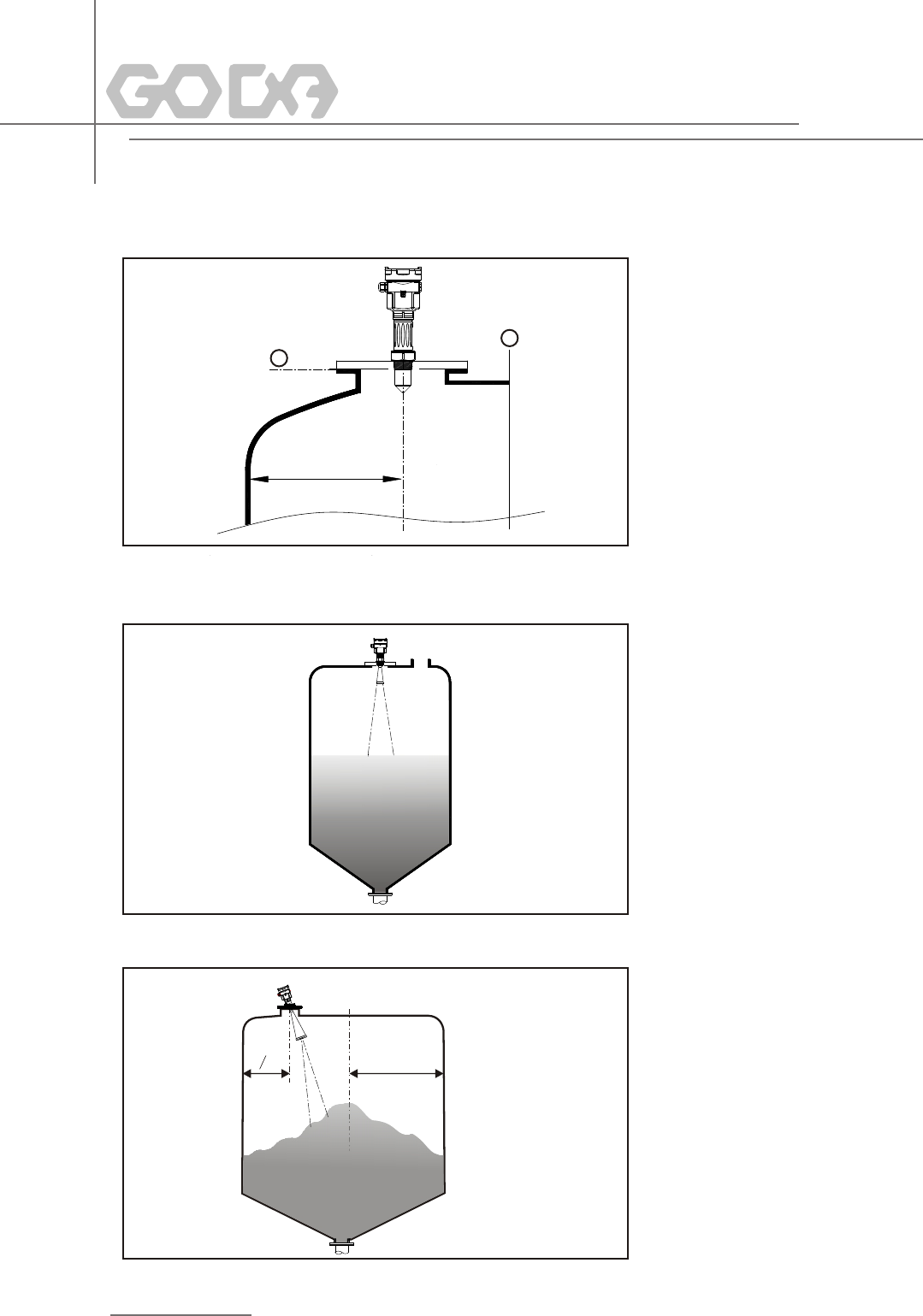
1.Reference Plane
2.Center of Vessel or Symmetrical
Axis
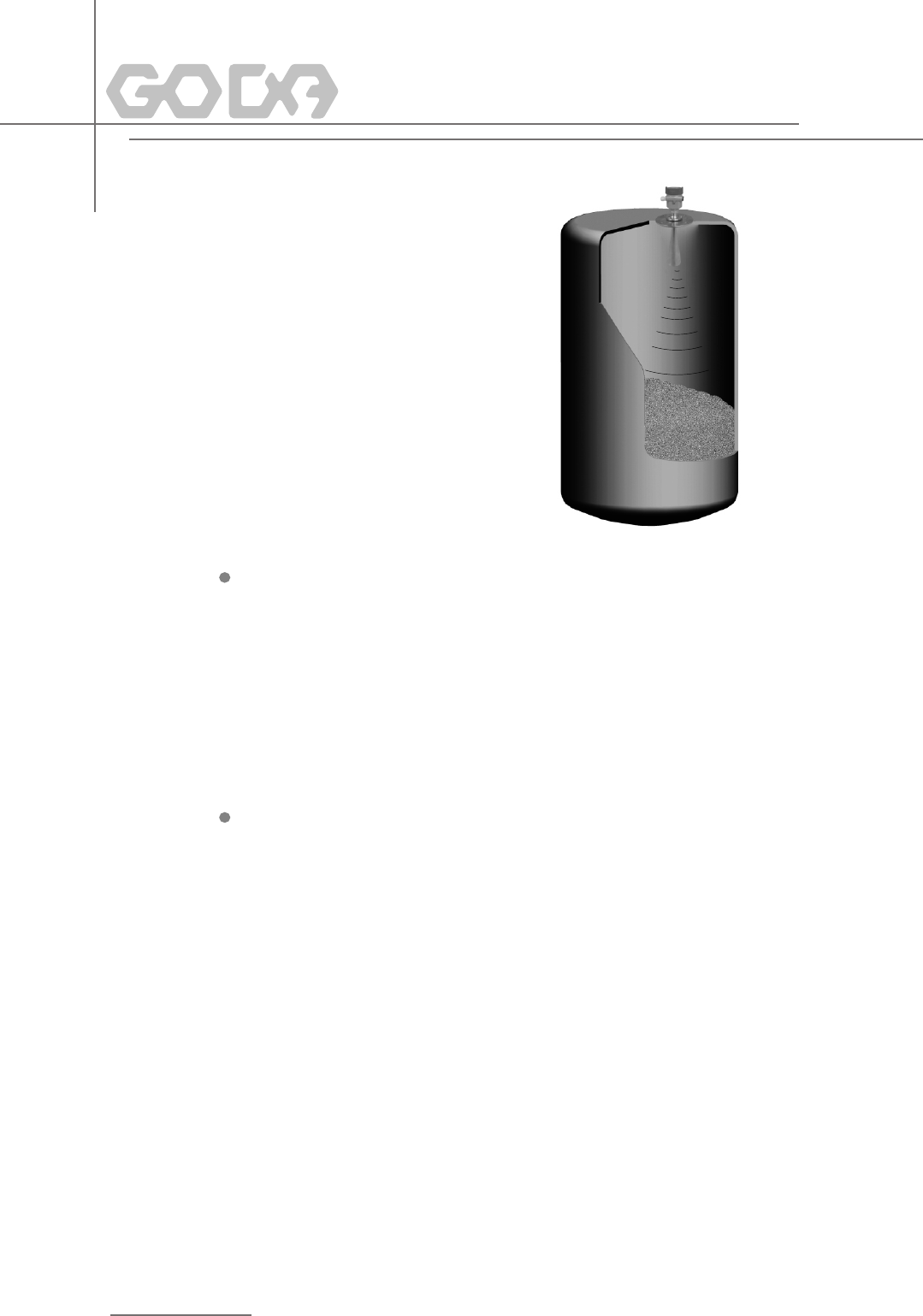
The best mounting position for a
conical vessel with flat top is the
center of its top, as the effective
measurement can reach the
bottom of vessel.
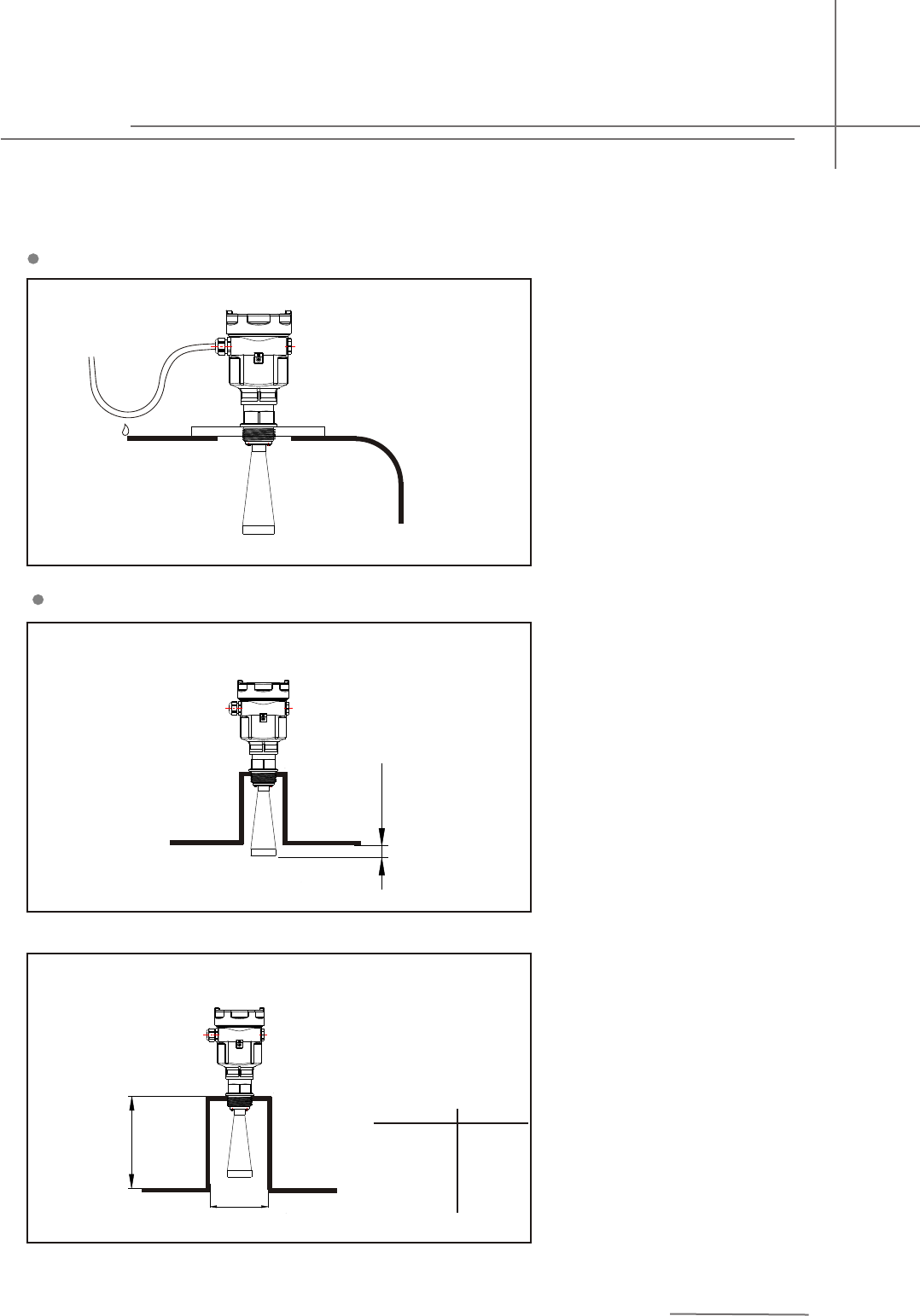
>10mm
d
h
d hma x
20 0m m
25 0m m
30 0m m
50 0m m
80 0m m
1½"
50mm(2")
80mm(3")
100mm(4")
150mm(6")
If the senser is mounted in a
socket extension that is too long,
strong false echoes are generated
which enterfere with the measurement.
Make sure that the horn antenna
protrudes out of the socket piece.
GDRD56 Antenna Extension
Damp-proof
Antenna Extension
9
In order to avoid dampness under
outdoor or humid indoor conditions
or for those instruments mounted
on cooling/heating vessels, seal
rings used on cables should be
screwed tight, plus the cable must
be bended downward outside
cable entry, indicated on the
diagram below
The transducer end must at
least protrude 10mm out of
socket.
Pulse Radar Level Instrument
d hmax
10 0m m
15 0m m
25 0m m
50mm(2")
80mm(3")
100 m m(4")
GDRD 57 Ex tens ion pi pe de mnst rati on
12
10
D
3
1
A大约
A
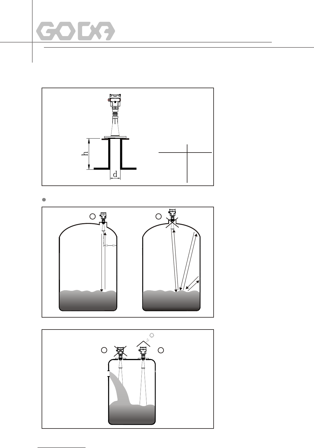
21 1.Correct
2.Wrong:Instruments are mounted
in the center of concave or arched
vassel tops, which results in
multiple echoes.
Rights and Wrongs in Mounting
1.Wrong: Mount the instrument
in/above filling stream, which
results in the measurement of
filling stream not the target medium.
2.Correct:
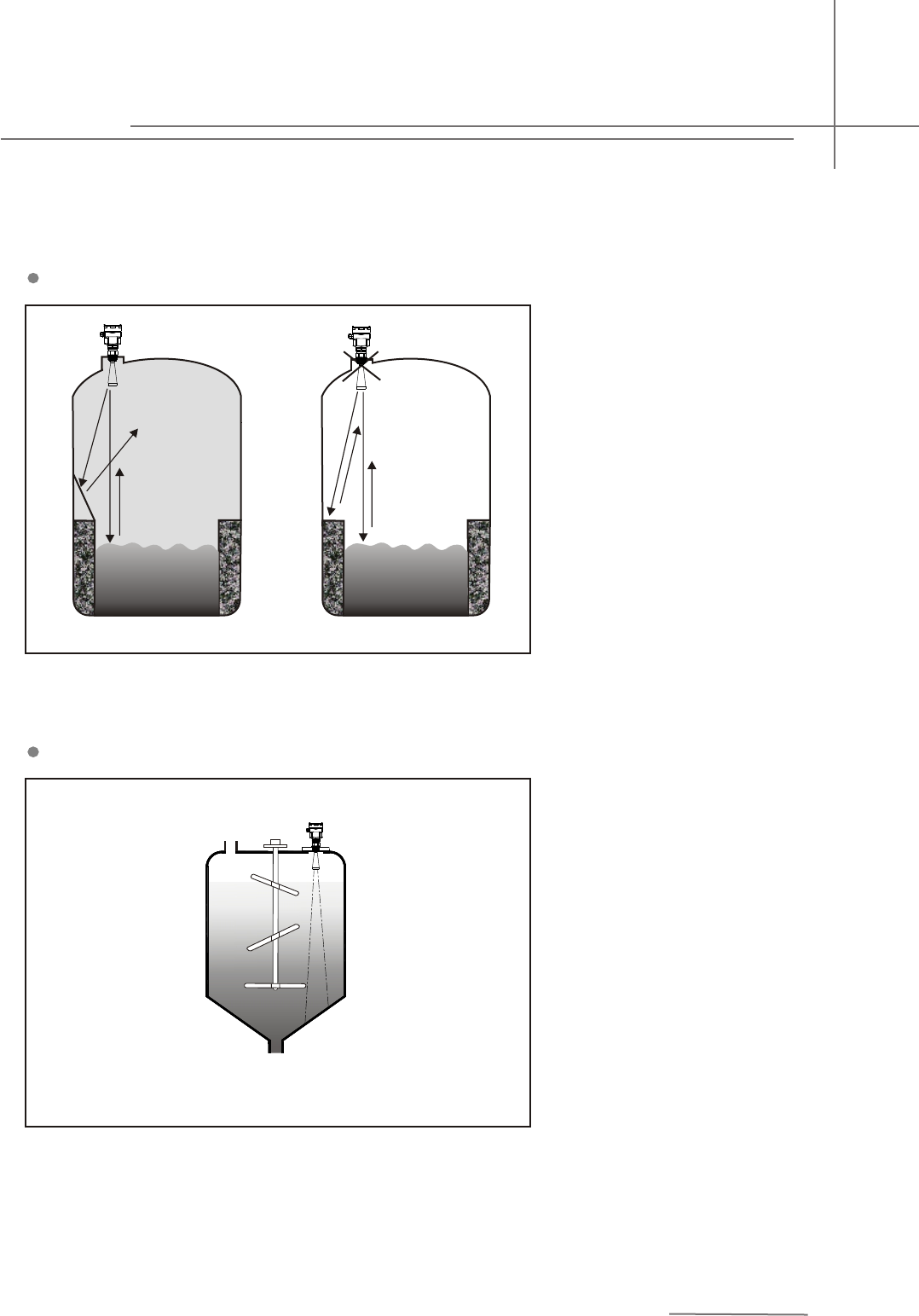
A
Reflection board installation
If there are barriers in vessels, it is
required to mount baffle-board, by
doing this, the echo reflected by the
barrier will be reflected out. And “False
Echo Storage” will be applied.
11
If there are agitators in vessels,
instrument must be mounted as
far away from agitators as possible.
Once installation completed, a
"false echo learning" should be
carried out while agitators in
motion to eliminate negative
influence caused by false echo
of agitators. You are advised to
opt for installation with standpipe
if foam or wave is generated due
to the action of agitators.
Agitator
Pulse Radar Level Instrument
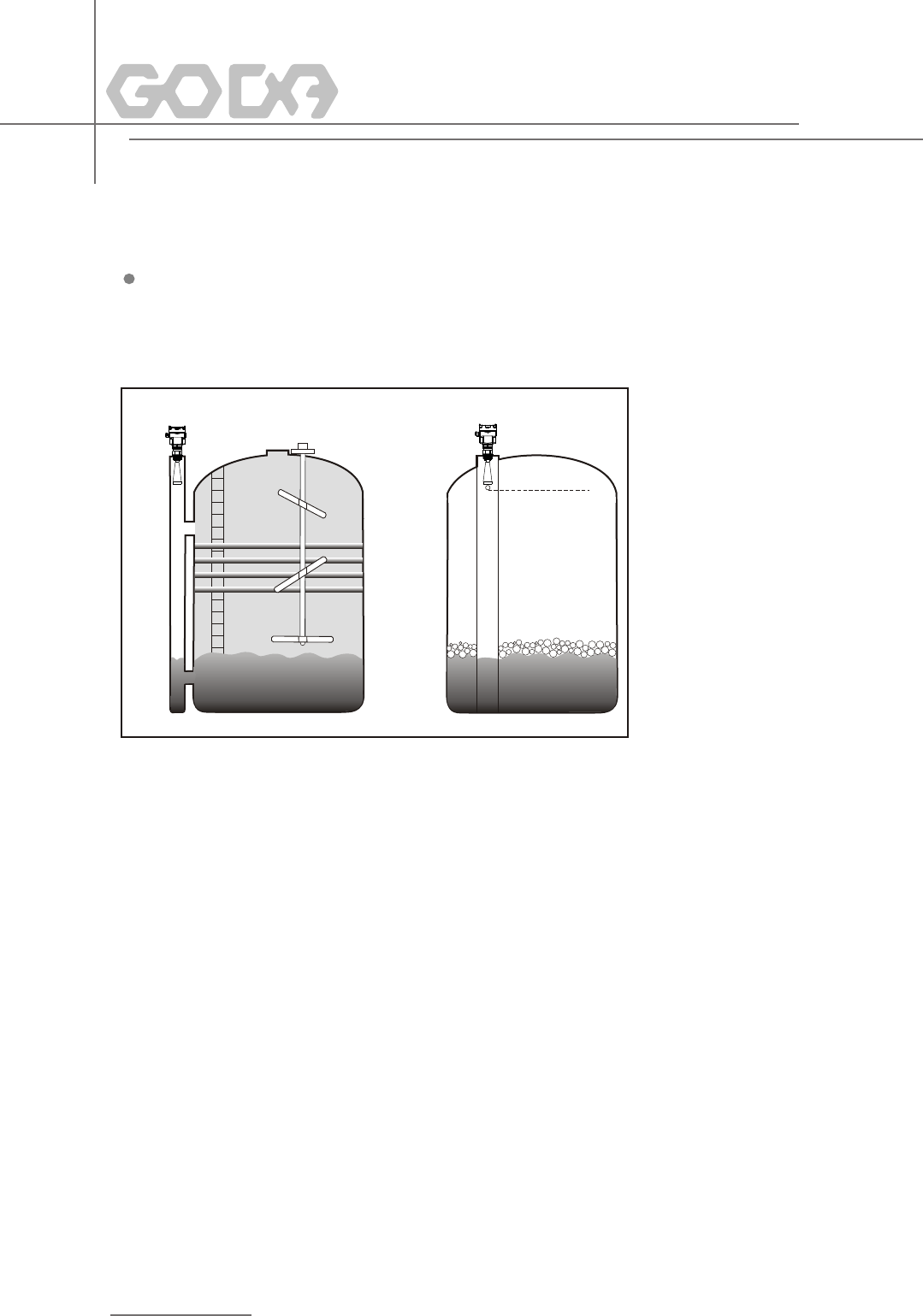
Installation with Standpipe
You are advised to opt for installation
with standpipe (or bypass tube) to avoid
the influence on measurement caused
by barriers inside vessels or foam
generation.
It is advised to install antenna inside
of the standpipe to avoid the error
caused by foam. The minimum inner
diameter of standpipe should be 50mm.
Avoid large cracks or welding seam
when connecting standpipe. False
echo storage must be carried out as
well in this case.
ventilation hole
A
Note: You must NOT mount instrument inside standpipe while
measuring adhesive medium.
Side through Standpipe installation with Standpipe
12
By using standpipe, the influence of foams can be reduced.
13
Power supply and current signal are carried by the same two-wire connection cable.
This equipment is not allowed to be connected to public utility power lines.
See the Technical Specifications of this guide for detailed requirement on power
supply. A safety barrier should be placed between power supply and instrument for
intrinsically safe version.
See the Technical Specifications of this guide for detailed requirement on power supply.
Earth-connected current output can be used for standard version of level instruments,
while the explosion proof version must be operated with a floating current output. Both
instruments and earth terminals should be connected with ground firmly and securely.
Normally you can either choose to connect with the earth terminal on vessel or adjacent
ground in case of plastic vessels.
Standard 2-wire cable with outside diameter of 5...9mm, which assures the seal effect
of cable entry, can be used as feeder cable. You are recommended to use screened
The two ends of shielded cable must be connected with earth terminal. The shielded
cable must be connected with inner earth terminal directly inside the transducer, while
the outside earth terminal on housing must be connected with ground. In the event of
earth-connected current, the shielding side of shielded cable must be connected to
ground potential via a ceramic capacitor (e.g. : 1μF 1500V) in order to dampen the low
frequency grounding current and avoid the disturbance caused by high frequency signals
5 Electrical Connection
Power Supply
General Introduction
20mA/HART(2-Wire)
Cable Connection
Shielding & Grounding
2-wire
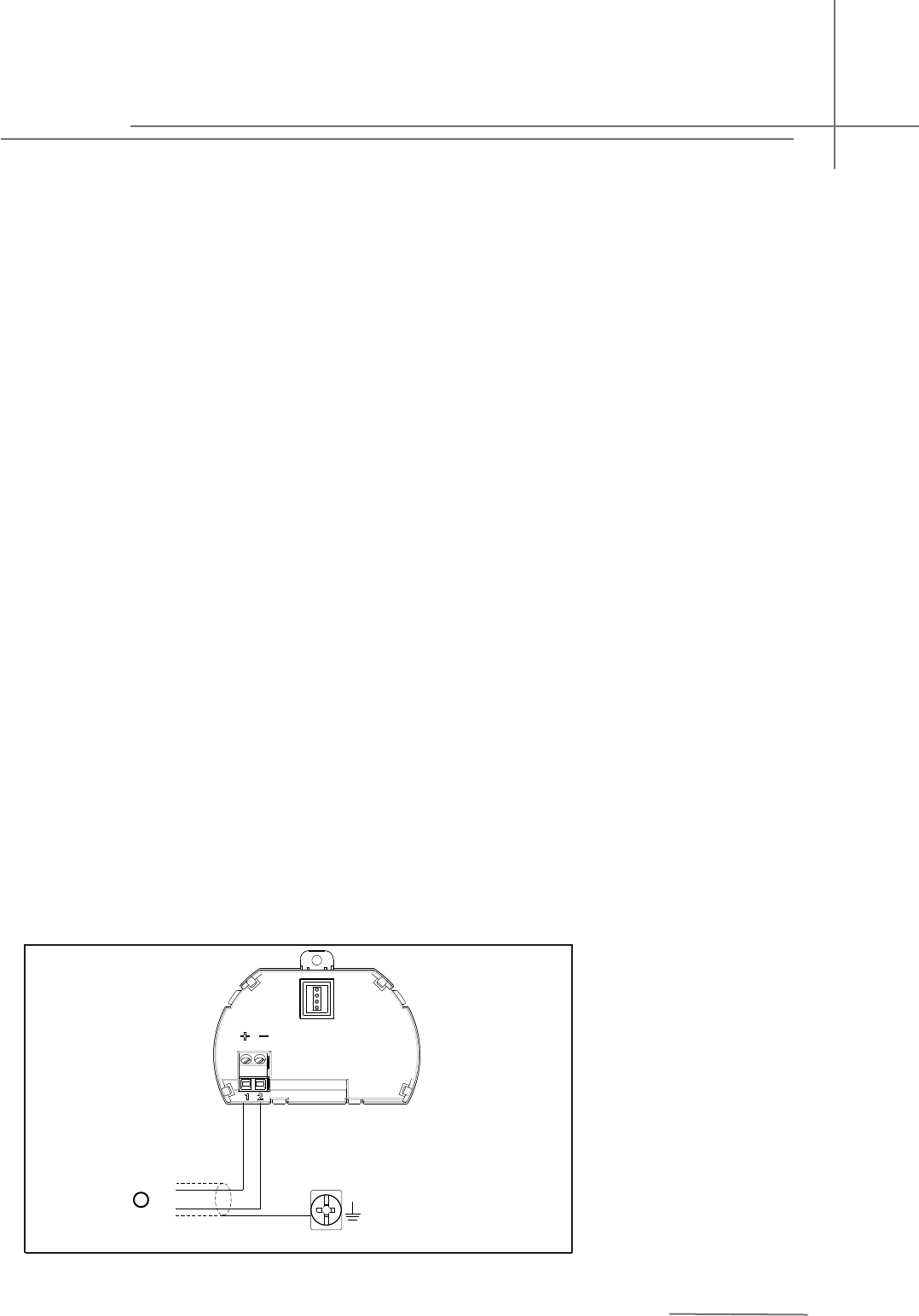
Wiring Diagram
2-wire wiring used for HART
1)Power Supply and Signal Output
+
-
1
Pulse Radar Level Instrument
65
321
4
(4~2 0)m A IN (4~20)mA O U T
24V OUT 2 4V I N
FBS-2
COMW A Y G O D Aware
(4~20)mA
65
321
4
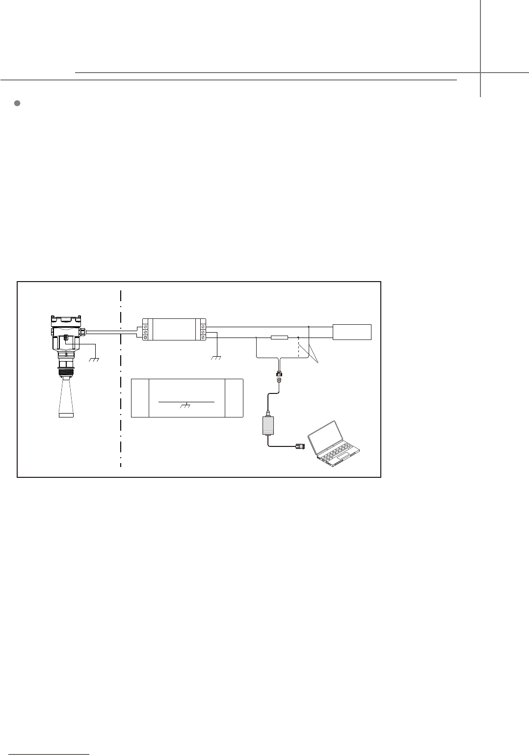
Explosion Proof Connection
This product is an intrinsic safety explosion proof version (Exia ⅡC T6 Ga) with stainless steel housing and
plastic-encapsulated internal structure aimed to prevent sparks resulted from transducer and circuit malfunction
from leaking out. It is applicable for the non-contact continuous level measurement of flammable medium under
the level of explosion proof inferior to Exia ⅡC T6 Ga. You are required to use series (intrinsic safety explosion
proof: [Exia] ⅡC,voltage of power supply: 24V DC±10%,short-circuit current: 114mA,operating current:
4...20mA) of safety barriers, which are supplementary to this product, for the power supply of this product.
All connection cables must be screened with max. length of 500m. Stray capacitor≤0.1μF/Km,stray inductance
≤1mH/Km. The level measurement instrument must be connected to ground potential and unapproved
supplementary devices are not allowed to use.
Explosion Proof Zone None-Explosion-Proof Zone
Adjust with GODAware
choose either one
Pulse Radar Level Instrument
14
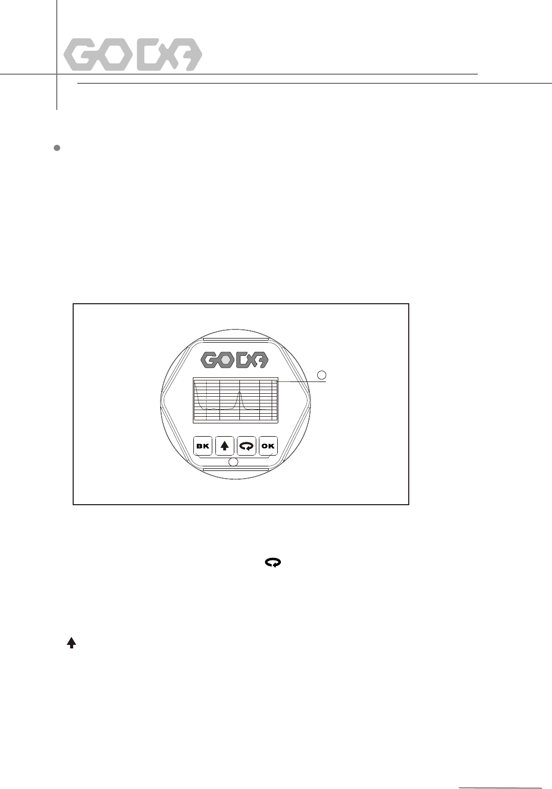
Display/Adjustment Module
1
2
0. 0 0
0
10
20
30
40
50
60
70
80
90
10 0
11 0
12 0
dB
2. 0 0 3. 0 0 4. 0 0 5 . 00
1 LCD 2 Adjustment Keypad
1
2
[ ]Keypad
-Enter programming mode;
-Confirm programming options;
-Confirm modifications to parameters.
OK[ ]Keypad
-Choose programming options;
-Choose the digit of parameters to edit;
-Display the contents of parameters.
[ ]Keypad
-Modify parameter values.
[ ]Keypad
-Programming mode exit;
-Return to higher menu level.
Shortcut
[ ]Display Echo wave
KB
KB
6 Adjustment Instructions
Adjustment Methods
Three adjustment methods available for GDRD series :
1.Display/Adjustment Module
2.Adjustment software GODAware
3.HART handheld programmer
ViewPoint is a pluggable display/adjustment module. The adjustment can be done through operating with four
buttons on ViewPoint. Optional menu operation languages are available for selection. ViewPoint is only used for
display after adjustment in that the measurement results can be seen clearly through the glass window.
15
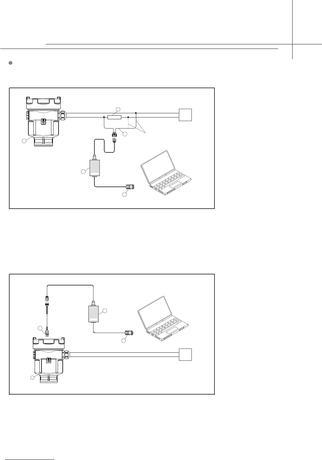
Connect with another unit throuth HART.
1 RS232 Connect Cable/USB port
2 GDRD series
3 HATR pont adapter used on COMWAY convertor
4 250 ohm Resistance
5 COMWAY Convertor
1 RS232 Connect Cable/USB port
2 GDRD series
2
3 I C adapter pont used on MOMWAY convertor
4 COMWAY Convertor
3
4
2
1
+
- DC
CO M WAY
GODAware
1
5
2
3
4
+
- DC
CO M WAY
GODAware
Choost Either One
2
Connect with another unit throuth I C.
GODAware
Pulse Radar Level Instrument
16
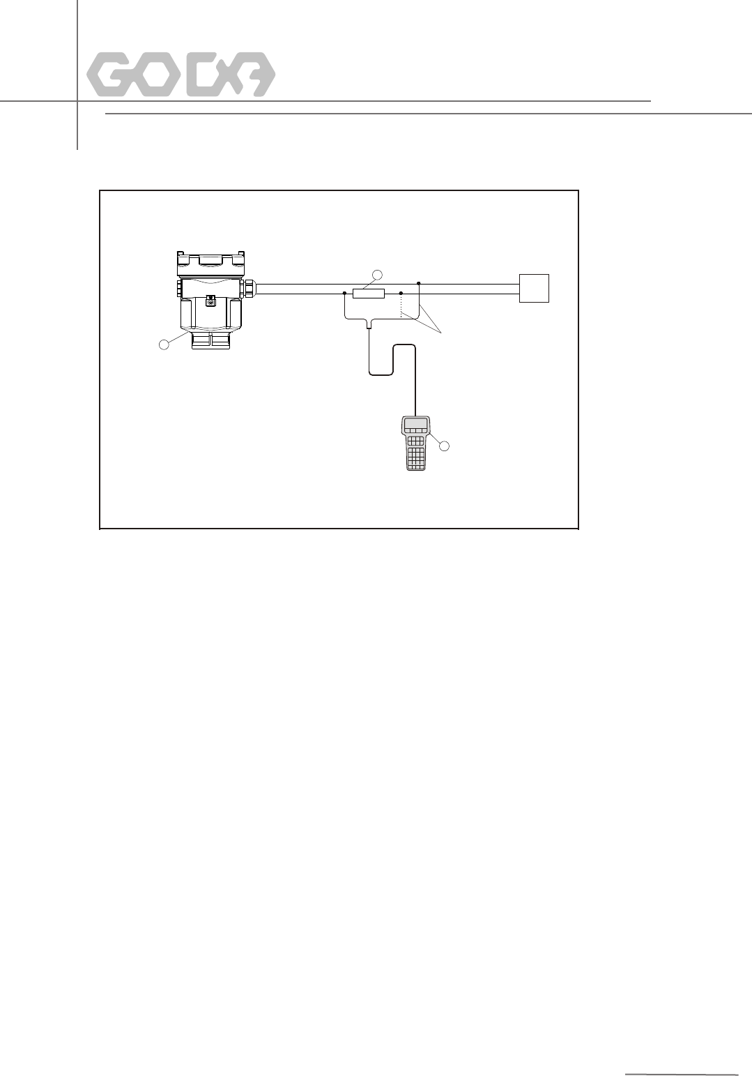
HART Handheld Programmer
Adjust GDRD series with HART Handheld Programmer
1 HART Handheld Programmer
2 GDRD series
3 250 ohm Resistance
2
1
3
+
- DC
Choost Either One
17
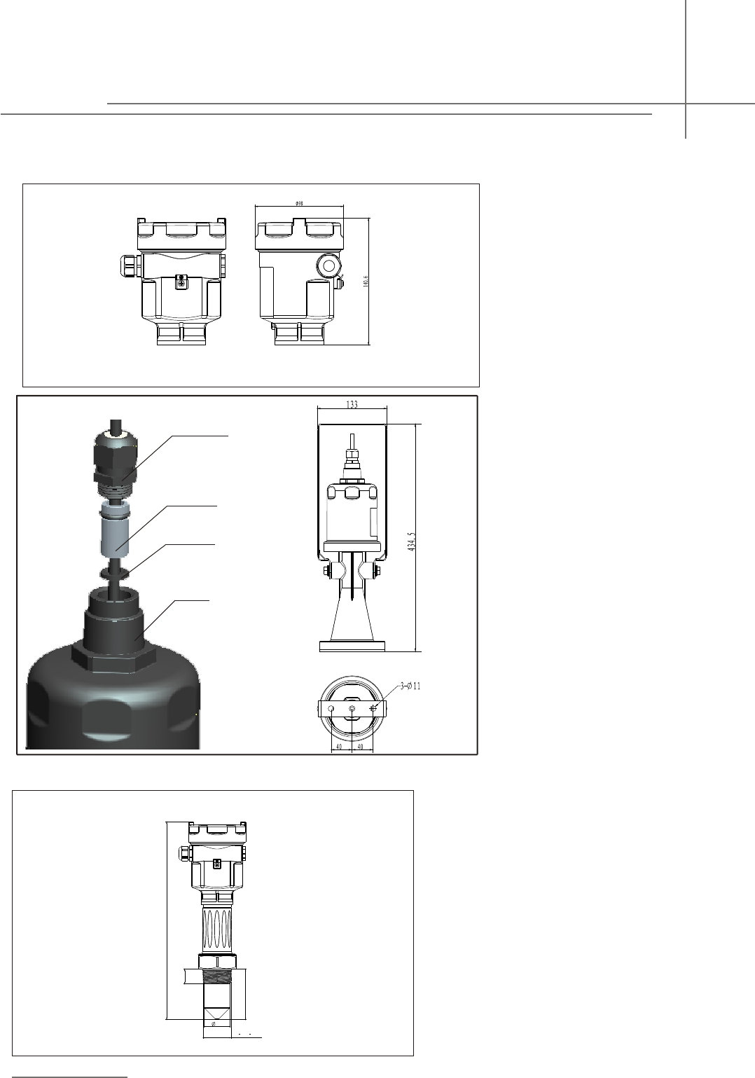
7 Dimension(Unit:mm)
Housing
Material: AL/PBT/316L
Pulse Radar Level Instrument
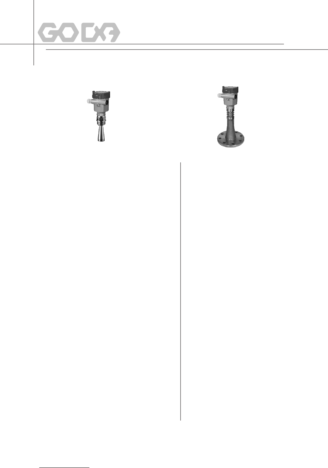
GDRD55 Threaded Vision
F
22
G11
2A(11
2NPT)
44
86.0
337.5
Nylon Sheath 1
Sealing Hose 2
Sealing Flat Gasket 3
Upper Cover 4
To install from 4 to 1.
To remove from 1 to 4.
Note:
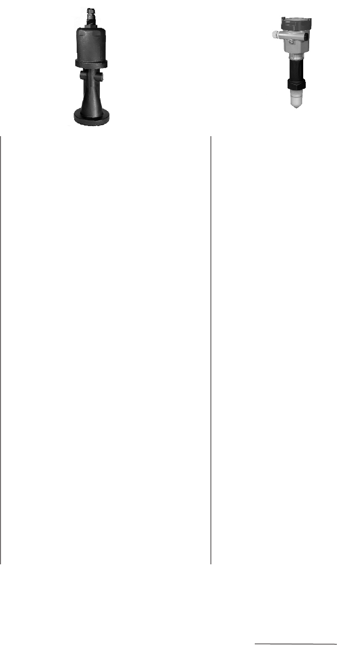
GDRD61
18
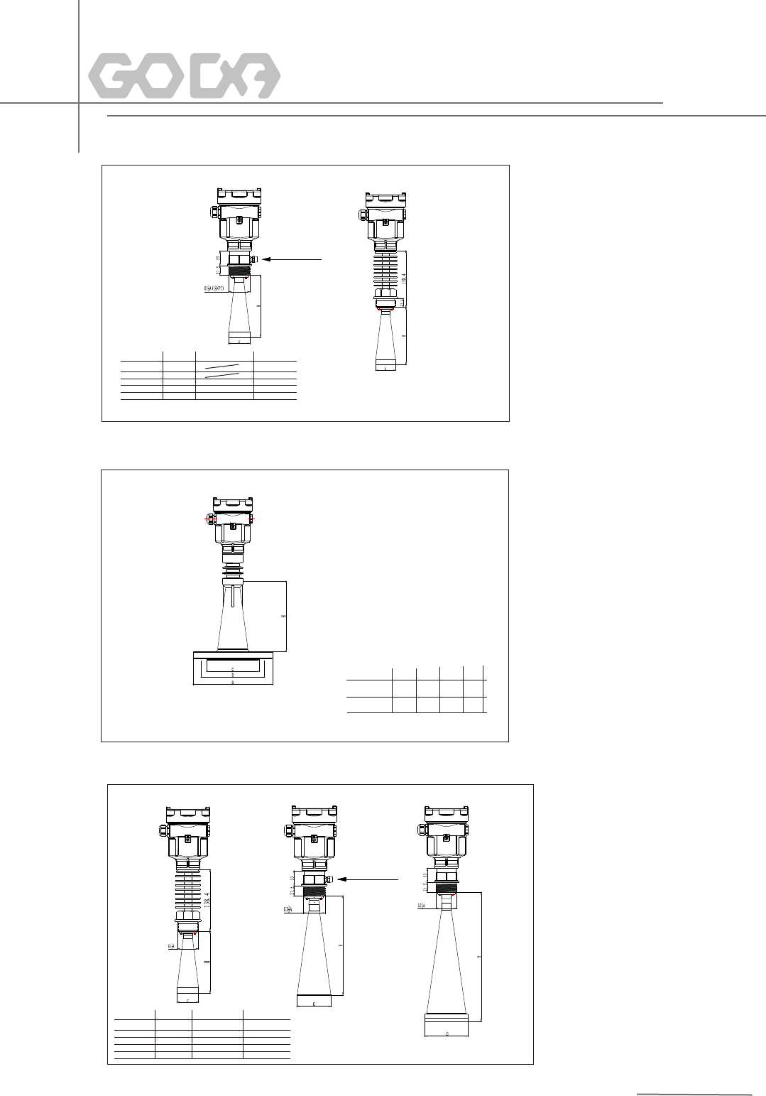
GDRD5 7 Flange Version
GDRD5 6 Threaded Vision
c (316L) )
(16L Shi eH H 3 el
148 40
Φ
7 78 Φ 22
20
98 88 30 Φ
1 20 223 6 Φ 6 5
a b
c H
DN80 PN1.6
Φ200 Φ160
Φ132
174
DN100 PN1.6
Φ220 Φ180 Φ156
260
Huff
GDRD58 Threaded Vision
c ( Shi eel ) H(36L)16
1 H 3L
Φ48 40
1 -
78 227 -
Φ
Φ98 288 300
Φ123 620 625
Huff
19
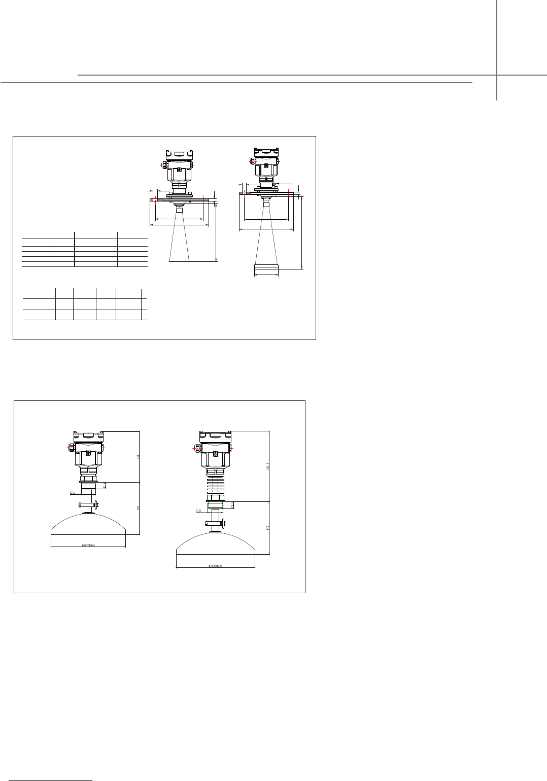
GDRD58 Gimbal Flange
a
b d
H
DN 00/4"
1
DN 25/5
1 "
m
220m
m250m
180 m m
m210m
11.mm
5
.mm11 5
Φ18
8x mm
Φ188x mm
c H1(316L) H1(316L Shield)
Φ48 140
- -
22778 - -
Φ
Φ98 0
288 30
3 620 6212 5 -Φ
Pulse Radar Level Instrument
c
H
a
n×d
H1
b
H
b
a
n×d
H1
Hff
u
GDRD58/59 Threaded Vision
20
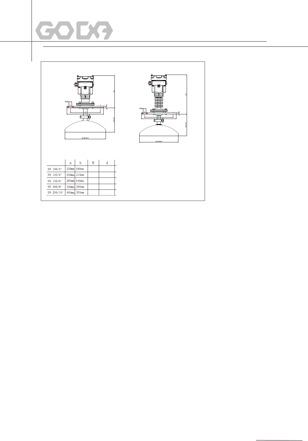
GDRD58/59 Gimbal Flange
10mm
10mm
10mm
10mm
10mm
4×φ18mm
4×φ18mm
4×φ22mm
4×φ22mm
4×φ26mm
21
Housing Aluminium,Stainless Steel 316L
Seal ring between housing and housing cover Silicone
ViewPoint window on housing Polycarbonate
Ground terminal Stainless Steel
Weight
-GDRD61 1.6kg
-GDRD55 1kg(Depend on process connections and housings)
-GDRD56 2kg(Depend on process connections and housings)
-GDRD57 3kg(Depend on process connections and housings)
-GDRD58 7kg(Depend on process connections and housings)
-GDRD59 2kg(Depend on process connections and housings)
Standard Version (21.6~26.4)V DC
Power Consumption max.22.5mA
Ripple Allowed
-<100Hz Uss<1V
-(100~100K)Hz Uss<10mV
General Parameters
ThreadG1½A ThreadG1½A ThreadG1½A
Flange 316LFlange 316L
PP/PFA PFA Stainless Steel316L
PFA
Stainless Steel 316L
PFA
Stainless Steel316L
PFA
GDRD55 GDRD56 GDRD57 GDRD58 GDRD59
Thread1½NPT
Thread1½NPT
series/Type
Process
Connection
Material
8 Technical Specifications
Cable Entry/Plug One cable entry of M20x1.5(cable diameter of 5~9m),
one binding of M20x1.5
2
Spring Connection Terminal Applicable for cables with cross section of 2.5mm
Parameters on Cable
Output Output Signal 4...20mA/HART
Resolution 1.6μA
Fault Signal Constant current output: 20.5mA;
22mA;3.9mA
-2-wire load resistance See diagram below
Integration Time 0...40sec, adjustable
Weight
Power
2-wire
Thread1½NPT
ThreadG1½A
Flange 316L
Thread1½NPT
Pulse Radar Level Instrument
GDRD61
Lifting Frame
Thread 1"NPT
Aluminum
PP
22

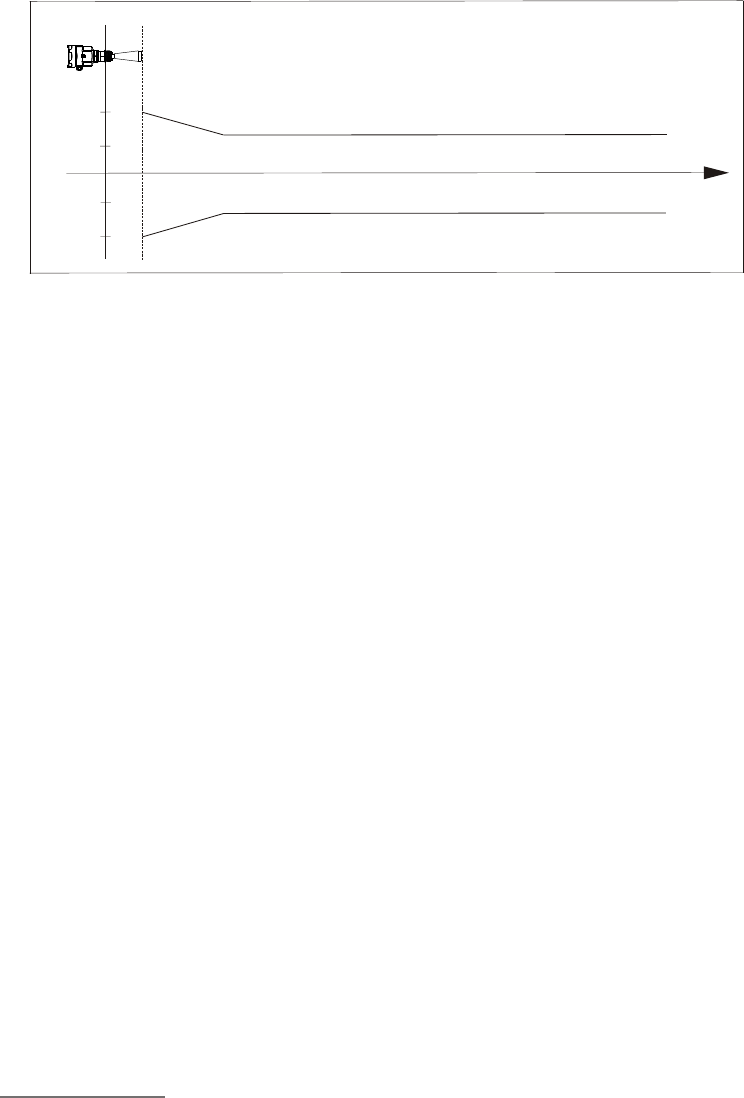
Blanking Distance End of Antenna
Max Measurement Distance
-GDRD55 10m(liquid)
-GDRD56 30m(liquid)
-GDRD57 20m(liquid)
-GDRD58 70m (solid)
-GDRD59 15m (solid)
-GDRD61/61L 30m/70m(liquid)
Measurement Interval About 1sec(Depend on parameter settings)
Adjustment Time About 1sec(Depend on parameter settings)
Resolution of Display 1mm
Accuracy See the diagram below
o
Temperature for Storage/Transport (-40~100)C
Process Temperature (Probe)
o
-GDRD55 (-40~130)C
o
-GDRD56 (-60~400)C
o
-GDRD57 (-40~150)C
o
-GDRD58 (-60~400)C
o
-GDRD59 (-40~200)C
o
-GDRD61 (-40~100)C
Relative Humidity <95%
Pressure Max.40MPa
2
Vibration Proof Mechanical vibration10m/s 10m /s ,10~150Hz
Characteristic
parameter
23
Pulse Radar Level Instrument
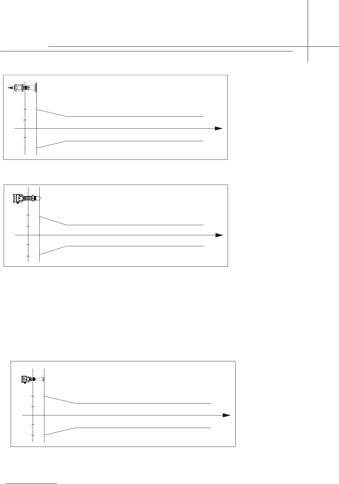
GDRD56
Accuracy See the accuracy illustration diagram below
-10mm
-3mm
3mm
0.5m 30m
10mm
Accuracy See the diagram left
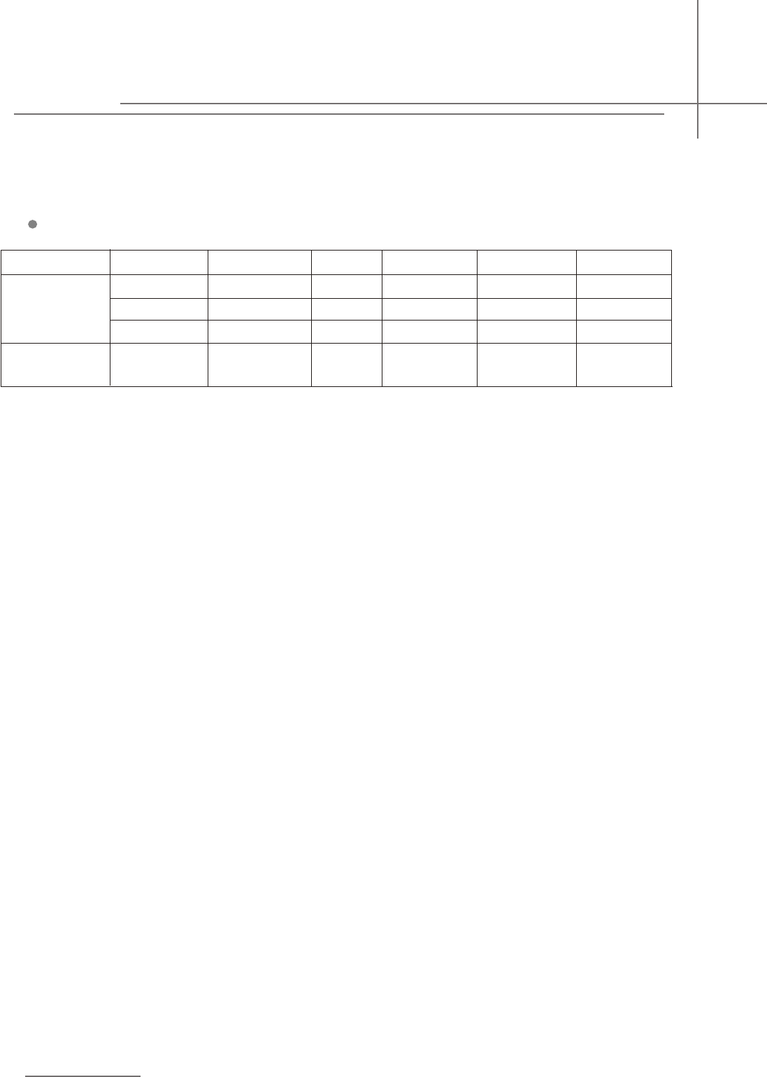
GDRD55
-10 m m
-5m m
5mm
0.5 m 10m
10m m
1) The generation of accurate measurement results needs longer time than usual in the event of drastic level changes(mx. Error 10%).
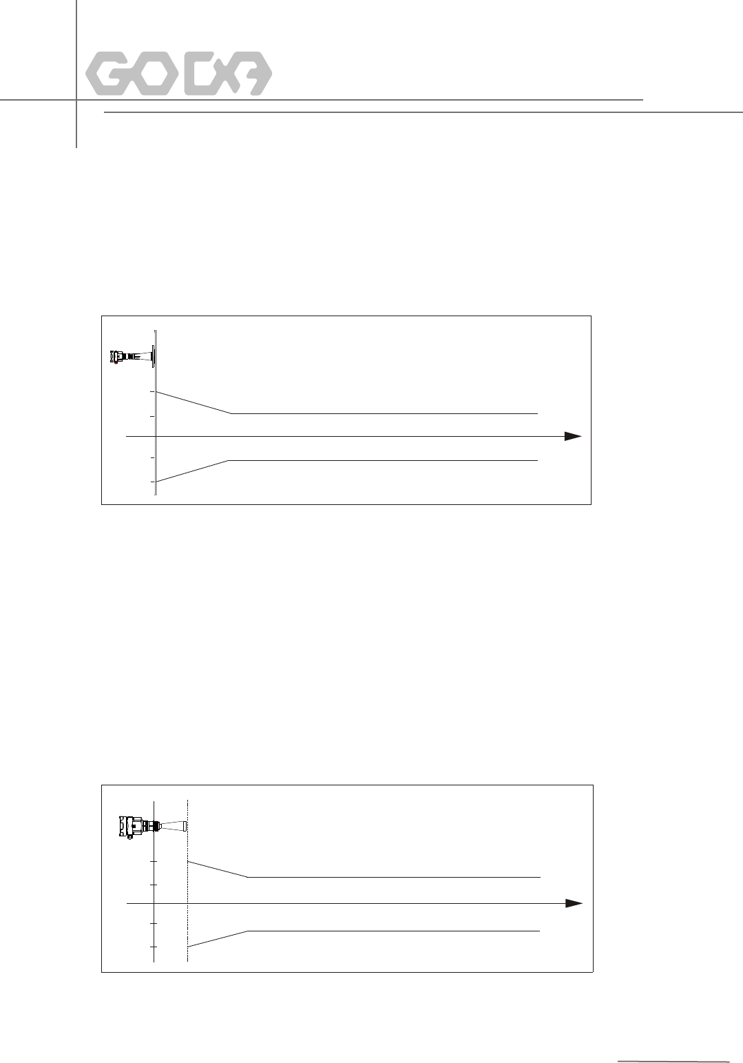
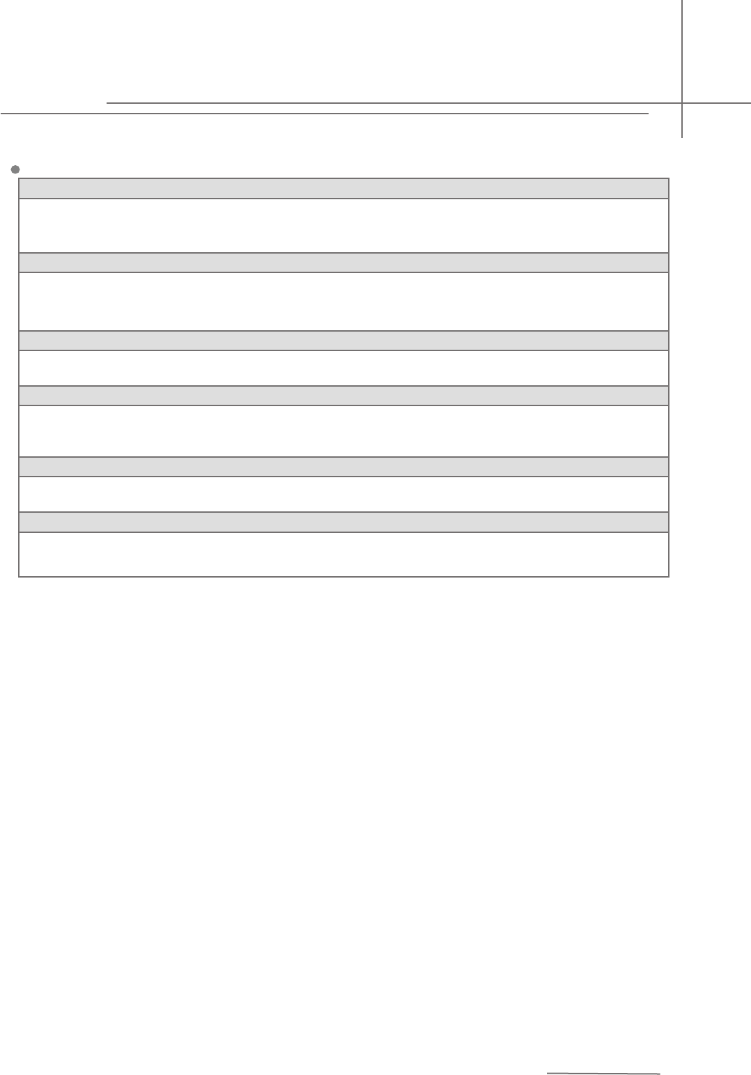
GDRD61
Accuracy See the diagram below
-10mm
-3mm
3mm
0.5m 30m
10mm
24
-30mm
-15mm
15mm
1.0m 70m
30mm
GDRD58
Accuracy See the accuracy illustration diagram below
GDRD57
Accuracy See the accuracy illustration diagram below
-10mm
-3m m
3mm
1.0 m 20m
10mm
25
GDRD59
Accuracy See the accuracy illustration diagram below
-15mm
m
-10m
10mm
1.0m 30m
15mm
26
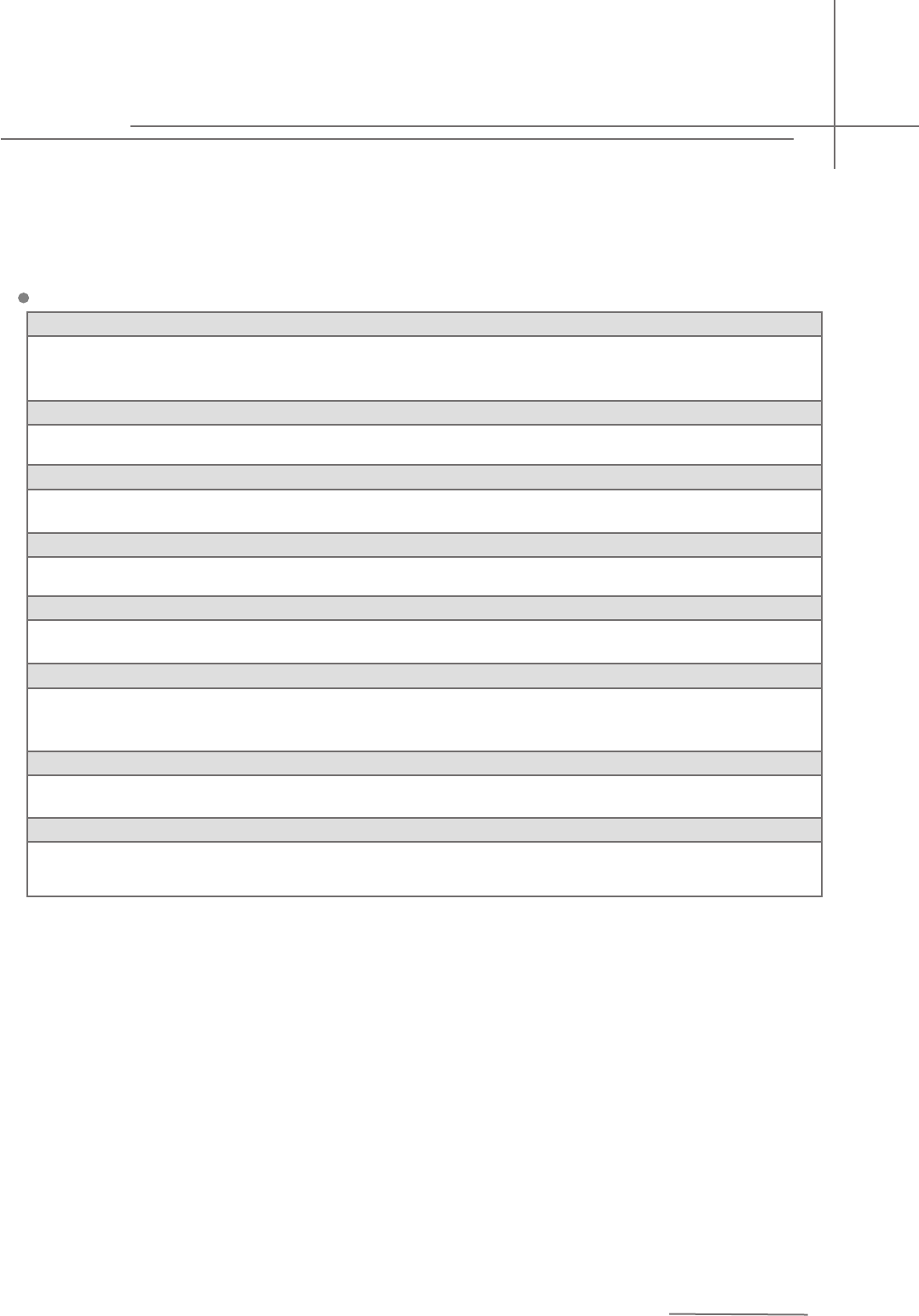
GDRD55
Explosion Proof Approval
P Standard
I Intrinsically Safe(Exia IIC T6 Ga)
Shape of Antenna/Material
B (R)Airproof HornΦ44mm/L86
N (R)Airproof HornΦ44mm/L108
Process Connection/Material
GP (F)Thread G1½A
NP (F)Thread 1½NPT
Length of Vessel Socket
A NO
Electronic
B (4~20)mA/HART2-Wire
Housing/Protection
A Aluminium/IP67
Cable Entry
M M20x1.5
N ½NPT
Display/Programming
A Yes
X No
27
Pulse Radar Level Instrument
9 Selection & Ordering Information
GDRD56
Explosion Proof Approval
P Standard
I Intrinsically Safe(Exia IIC T6 Ga)
Shape of Antenna/Material
C (T)Horn Φ78mm/L227/Stainless Steel 316L
H (T)Horn Φ98mm/L288/Stainless Steel 316L
J (T)Horn Φ123mm/L620/Stainless Steel 316L
Z (Z)Horn Φ78mm/Flexible/Stainless Steel 316L
Process Connection/Material
GP (H)thread G1½A/Stainless Steel 316L
GA (H)thread 1½NPT/Stainless Steel 316L
GB (G)thread G1½A/PP
o
GC (J)thread G1½A/Stainless Steel 316L/temperature(-60~250)C
GE (I)thread G1½A/Stainless Steel 316L(Huff)
Flange/Material
F0 No
Seal/Process Temperature
o
2 Viton(-60~150)C
o
3 Kalrez(-60~250)C
o
4 Graphite(-60~400)C
Electronic
B (4~20)mA/HART 2-Wire
Housing/Protection
A Aluminium/IP67
28
DN50 FA FB FC
DN80 GA GB GC
DN100 HA HB HC
DN125 IA IB IC
PP(L) PTFE(L) Stainless Steel(M)
Spec Code
Material
Cable Entry
M M20x1.5
N ½NPT
Display/Programming
A Yes
X No
GDRD57
Explosion Proof Approval
P Explosion Proof Approval
I Intrinsically Safe(Exia IIC T6 Ga)
Shape of Antenna/Material
C (U)Stainless Steel&PFA Flange DN80
D (U)Stainless Steel&PFA Flange Dn100
Electronic
B (4~20)mA/HART 2-Wire
Housing/Protection
A Aluminium/IP67
Cable Entry
M M20x1.5
N ½NPT
Display/Programming
A Yes
X No
29
Pulse Radar Level Instrument
GDRD58
Explosion Proof Approval
P Explosion Proof Approval
I Intrinsically Safe(Exia IIC T6 Ga)
Shape of Antenna/Material
C (T)Horn Φ78mm/L227/Stainless Steel316L
H (T)Horn Φ98mm/L288/Stainless Steel316L
J (T)Horn Φ123mm/L620/Stainless Steel316L
M (V)Horn Φ98mm/L300/Stainless Steel316L/PFA Shield
P (V)Horn Φ123mm/L625/Stainless Steel316L/PFA Shield
Q (W)ParaboloidΦ198mm/Stainless Steel316L
R (W)ParaboloidΦ246mm/Stainless Steel316L
Z (Z)Horn Φ78mm/Flexible/Stainless Steel316L
Process Connection/Material
GP (H) Thread G1½A/Stainless Steel316L
GA (H) Thread 1½NPT/Stainless Steel316L
GB (G) Thread G1½A/PP
o
GC (J) Thread G1½A/Stainless Steel316L/ Temperature (-60~250)C
GE (I) Thread G1½A/Stainless Steel316L(Huff)
o
GF (E) Thread G1½A/Stainless Steel316L/Temperature (-60~250)C
Flange/Material
F0 No
Seal/Process Temperature
o
2 Viton(-60~150)C
o
3 Kalrez(-60~250)C
o
4 Graphite(-60~400)C
Electronic
B (4~20)mA/HART 2-Wire
Housing/Protection
A Aluminium/IP67
30
DN50 FA FB FC - -
DN80 GA GB GC - -
DN100 HA HB HC HD HE
DN125 IA IB IC ID IE
PP(L) PTFE(L) Stainless Steel(M)Gimbal Flange(PP)(N)Gimbal Flange(Stainless Steel)(P)
Spec Code
Material
Cable Entry
M M20x1.5
N ½NPT
Display/Programming
A Yes
X No
GDRD59
Explosion Proof Approval
P Explosion Proof Approval
I Intrinsically Safe(Exia IIC T6 Ga)
Shape of Antenna/Material
Process Connection/Material
GP (H) Thread G1½A/Stainless Steel316L
GA (H) Thread 1½NPT/Stainless Steel316L
GB (G)thread G1½A/PP
GE (I) Thread G1½A/Stainless Steel316L(Huff)
o
GF (E) Thread G1½A/Stainless Steel316L/Temperature (-60~250)C
Flange/Material
31
Pulse Radar Level Instrument
C (T)Horn Φ78mm/L227/Stainless Steel316L
H (T)Horn Φ98mm/288/Stainless Steel316L
J (T)Horn Φ123mm/L620/Stainless Steel316L
M (V)Horn Φ98mm/L300/Stainless Steel316L/PFA Shield
P (V)Horn Φ123mm/L625/Stainless Steel316L/PFA Shield
Q (W)Parabolic Φ198mm/Stainless Steel316L
R (W)Parabolic Φ246mm/Stainless Steel316L
Z (Z)Horn Φ78mm/Flexible
DN50 FA FB FC -
DN80 GA GB GC -
DN100 HA HB HC HE
DN125 IA IB IC IE
DN150 JA JB JC JE
DN200 KA KB KC KE
DN250 LA LB LC LE
PP(L) PTFE(L) Stainless Steel(M) Gimbal Flange(Stainless Steel)(P)
Spec Code
Material
F0 No
Seal/Process Temperature
o
2 Viton(-60~80)C
3
Electronic
B (4~20)mA/HART 2-Wire
Housing/Protection
A Aluminium/IP67
Cable Entry
M M20x1.5
N ½NPT
Display/Programming
A Yes
X No
o
Kalrez(-60~250)C
32
GDRD61
Explosion Proof Approval
P Standard(max measurement range of 30m)
I Intrinsically Safe Exia IIC T6 Ga
L Enhanced(max measurement range of 70m)
Shape of Antenna/Material
P Horn Φ78mm/L221/PA66
Process Connection/Material
GB THREAD 1″NPT PP
GD LIFTING FRAME
Electronic
B (4~20)MA/HART
Housing/Protection
A IP68
Programming
A
X No
Sunshield
A
X No
Cable
A
B Length of twin-core shielded(length:X m)
C Length of 7-core shielded lead(length:X m)
Standard twin-core shielded (leagth of 10m)
Yes
Yes

33
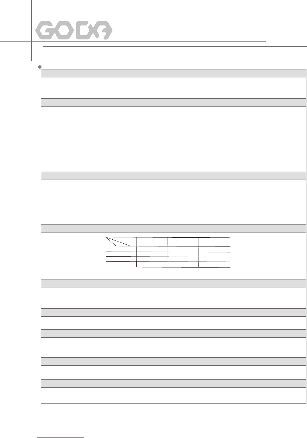
Approvals
Standard Version Intrinsically Safe Version(Exia IIB T6 Ga) Intrinsically Safe Version(Exia IIC T6 Ga)
Intrinsically Safe Version+Explosion Proof(Exdia [ia Ga] IIC T6 Gb)
Atmosphere Pressure Min. Norm. Max.
Atmosphere Form Foam Dust Deposit Vapour
Atmosphere
Contact:
Company:
Address:
P. C.: Tel:
Email: Fax:
Customer Information Please give brief explanation on the application of
instrument:
Date:
Measured Medium
Name
Condition Liquid Solid Form Mass Particle Dust)
Temperature: Min. C Norm. C Max. C
Surface Flat Turbulent Agitated Vorte
Dielectric Constant εr<3 εr>3
° ° °
10 Application Questionnaire
Installation
Filling Stream inlet position and installation position (Please specify in the diagram below)
Vessel
Process Connection
Critical Information
Height Diameter
Shape of Top Flat Arch Conical Horizontal
Mode: Top Side
Nozzle Length: Nozzle Diameter: Measurement Range:
Yes No
Communication
Display
(4~20)mA/HART
Circular Vessel Square Vessel
Thread( G1½A G2A
1½NP T
G1 A G1A、M105x2 )
Flange(DN= ) Swivelling Holder
NPT
3344
/
G A
3344
/
Pulse Radar Level Instrument

Beijing GODA Instruments Co.,Ltd.
Edition: GD/200902
Beijing GODA Instruments Co., Ltd.
(010)89759341 89759342 89759343 89759344
(010)89759327
102209
www.godacn.com
Email:sales@godacn.com
Sales Dept Of Beijing GODA Instruments Co., Ltd.
Add: Room1303, Block D, Ocean International Center,
No 62 Middle Of east 4th ring, Chaoyang Dist.,
Beijing,100025, China
(010)59648788( )
(010)59648789
100025
Add: Management Address:3RD Floor,Block B,
Hongxianhong base,Beiqijia Town,Changping
District,Beijing.
Tel:
Fax:
PC:
Website:
Tel: Ext.8
Fax:
PC: