Beijing GODA Instruments GDRD5Y6YA Pulse Radar Level Instrument User Manual FCC version11 19 for 209
Beijing GODA Instruments Co., LTD. Pulse Radar Level Instrument FCC version11 19 for 209
UserManual.wiki
>
Beijing GODA Instruments
>
GDRD5Y6YA User Manual
User Manual
Navigation menu
Upload a User Manual
Namespaces
Wiki Guide
HTML
PDF
Info
Views
User Manual
Discussion / Help
Navigation
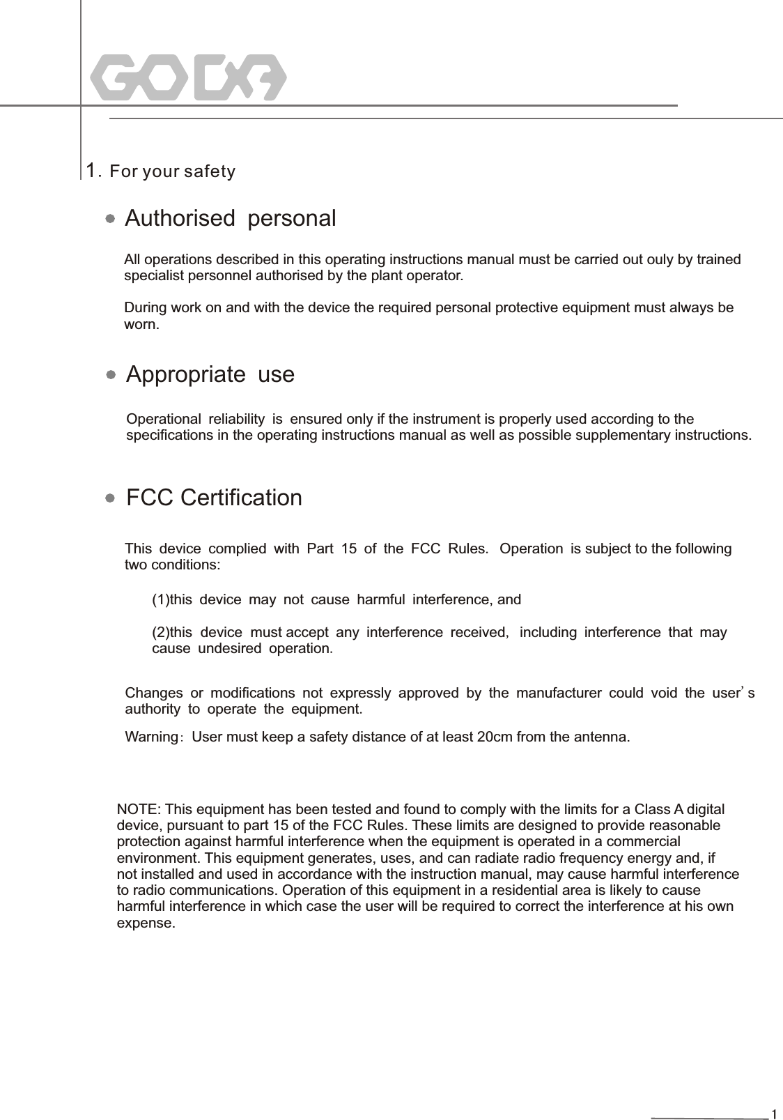
![653214(4~2 0)m A IN (4~20)mA O U T 24V OUT 2 4V I N FBS-2COMW A Y G O D Aware(4~20)mA653214Explosion Proof ConnectionThis product is an intrinsic safety explosion proof version (Exia ⅡC T6 Ga) with stainless steel housing andplastic-encapsulated internal structure aimed to prevent sparks resulted from transducer and circuit malfunction from leaking out. It is applicable for the non-contact continuous level measurement of flammable medium under the level of explosion proof inferior to Exia ⅡC T6 Ga. You are required to use series (intrinsic safety explosionproof: [Exia] ⅡC,voltage of power supply: 24V DC±10%,short-circuit current: 114mA,operating current: 4...20mA) of safety barriers, which are supplementary to this product, for the power supply of this product.All connection cables must be screened with max. length of 500m. Stray capacitor≤0.1μF/Km,stray inductance≤1mH/Km. The level measurement instrument must be connected to ground potential and unapproved supplementary devices are not allowed to use.Explosion Proof Zone None-Explosion-Proof ZoneAdjust with GODAwarechoose either one Pulse Radar Level Instrument14](https://usermanual.wiki/Beijing-GODA-Instruments/GDRD5Y6YA/User-Guide-2449686-Page-16.png)
![Display/Adjustment Module120. 0 0010203040506070809010 011 012 0dB2. 0 0 3. 0 0 4. 0 0 5 . 001 LCD 2 Adjustment Keypad12[ ]Keypad-Enter programming mode;-Confirm programming options;-Confirm modifications to parameters. OK[ ]Keypad-Choose programming options;-Choose the digit of parameters to edit;-Display the contents of parameters.[ ]Keypad-Modify parameter values.[ ]Keypad-Programming mode exit;-Return to higher menu level. Shortcut[ ]Display Echo waveKBKB6 Adjustment InstructionsAdjustment MethodsThree adjustment methods available for GDRD series :1.Display/Adjustment Module2.Adjustment software GODAware3.HART handheld programmerViewPoint is a pluggable display/adjustment module. The adjustment can be done through operating with four buttons on ViewPoint. Optional menu operation languages are available for selection. ViewPoint is only used for display after adjustment in that the measurement results can be seen clearly through the glass window.15](https://usermanual.wiki/Beijing-GODA-Instruments/GDRD5Y6YA/User-Guide-2449686-Page-17.png)
![33ApprovalsStandard Version Intrinsically Safe Version(Exia IIB T6 Ga) Intrinsically Safe Version(Exia IIC T6 Ga)Intrinsically Safe Version+Explosion Proof(Exdia [ia Ga] IIC T6 Gb)Atmosphere Pressure Min. Norm. Max.Atmosphere Form Foam Dust Deposit Vapour AtmosphereContact: Company: Address: P. C.: Tel:Email: Fax:Customer Information Please give brief explanation on the application of instrument: Date: Measured MediumName Condition Liquid Solid Form Mass Particle Dust) Temperature: Min. C Norm. C Max. C Surface Flat Turbulent Agitated VorteDielectric Constant εr<3 εr>3 ° ° °10 Application QuestionnaireInstallationFilling Stream inlet position and installation position (Please specify in the diagram below) VesselProcess ConnectionCritical InformationHeight Diameter Shape of Top Flat Arch Conical Horizontal Mode: Top Side Nozzle Length: Nozzle Diameter: Measurement Range: Yes No CommunicationDisplay (4~20)mA/HART Circular Vessel Square Vessel Thread( G1½A G2A 1½NP T G1 A G1A、M105x2 ) Flange(DN= ) Swivelling Holder NPT 3344/G A 3344/ Pulse Radar Level Instrument](https://usermanual.wiki/Beijing-GODA-Instruments/GDRD5Y6YA/User-Guide-2449686-Page-35.png)