Beijing InHand Networks Technology IR6X5 Industrial Cellular Router User Manual
Beijing InHand Networks Technology Co., Ltd. Industrial Cellular Router Users Manual
UserManual.wiki
>
Beijing InHand Networks Technology
>
IR6X5 User Manual
Users Manual
Navigation menu
Upload a User Manual
Namespaces
Wiki Guide
HTML
PDF
Info
Views
User Manual
Discussion / Help
Navigation
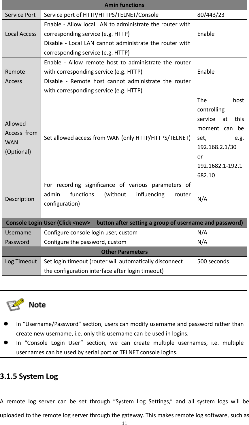
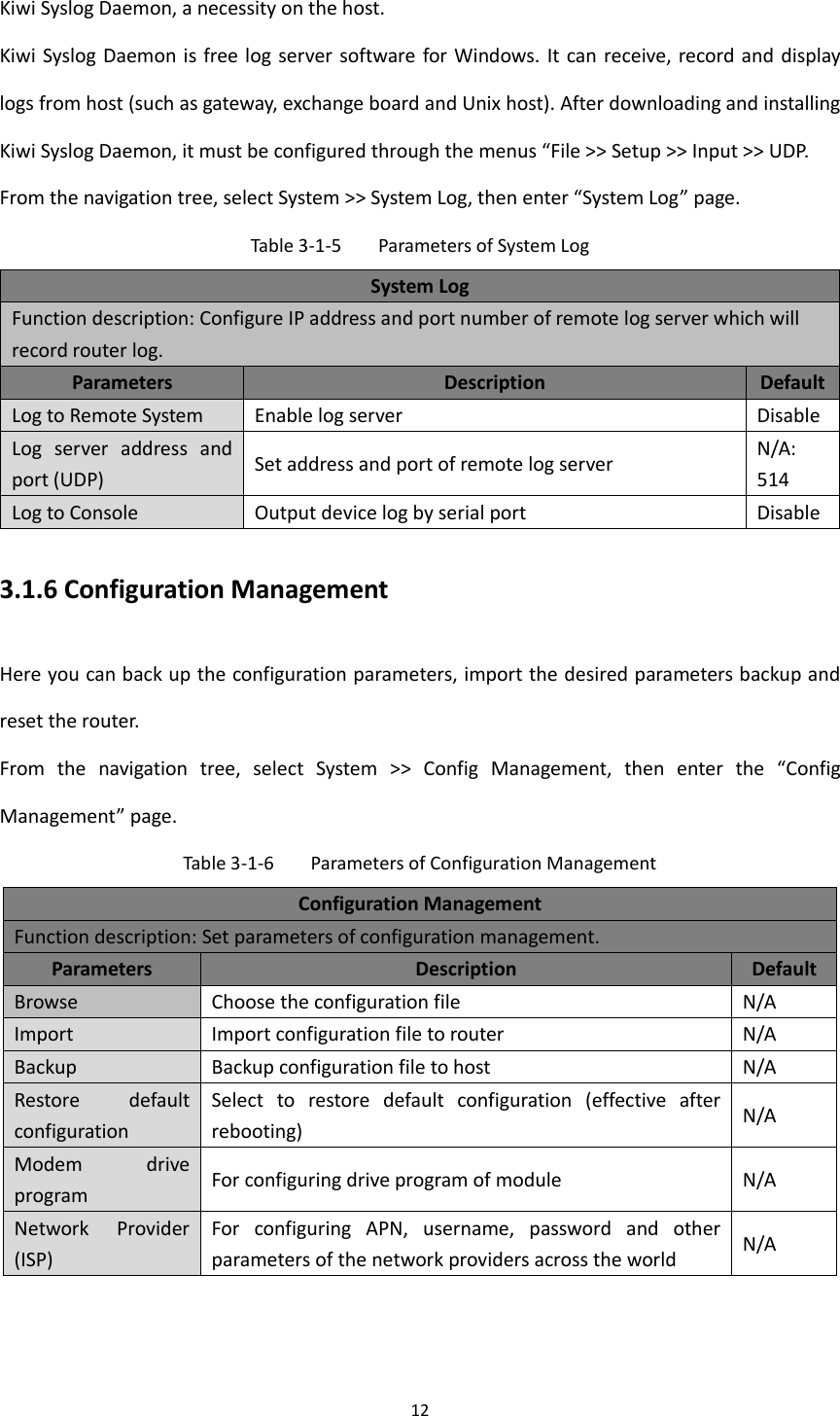
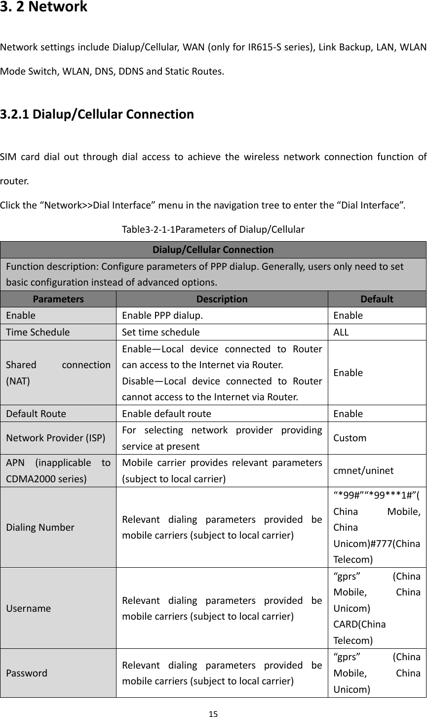
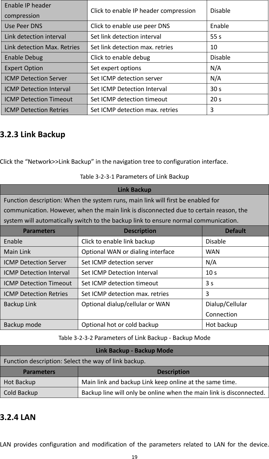
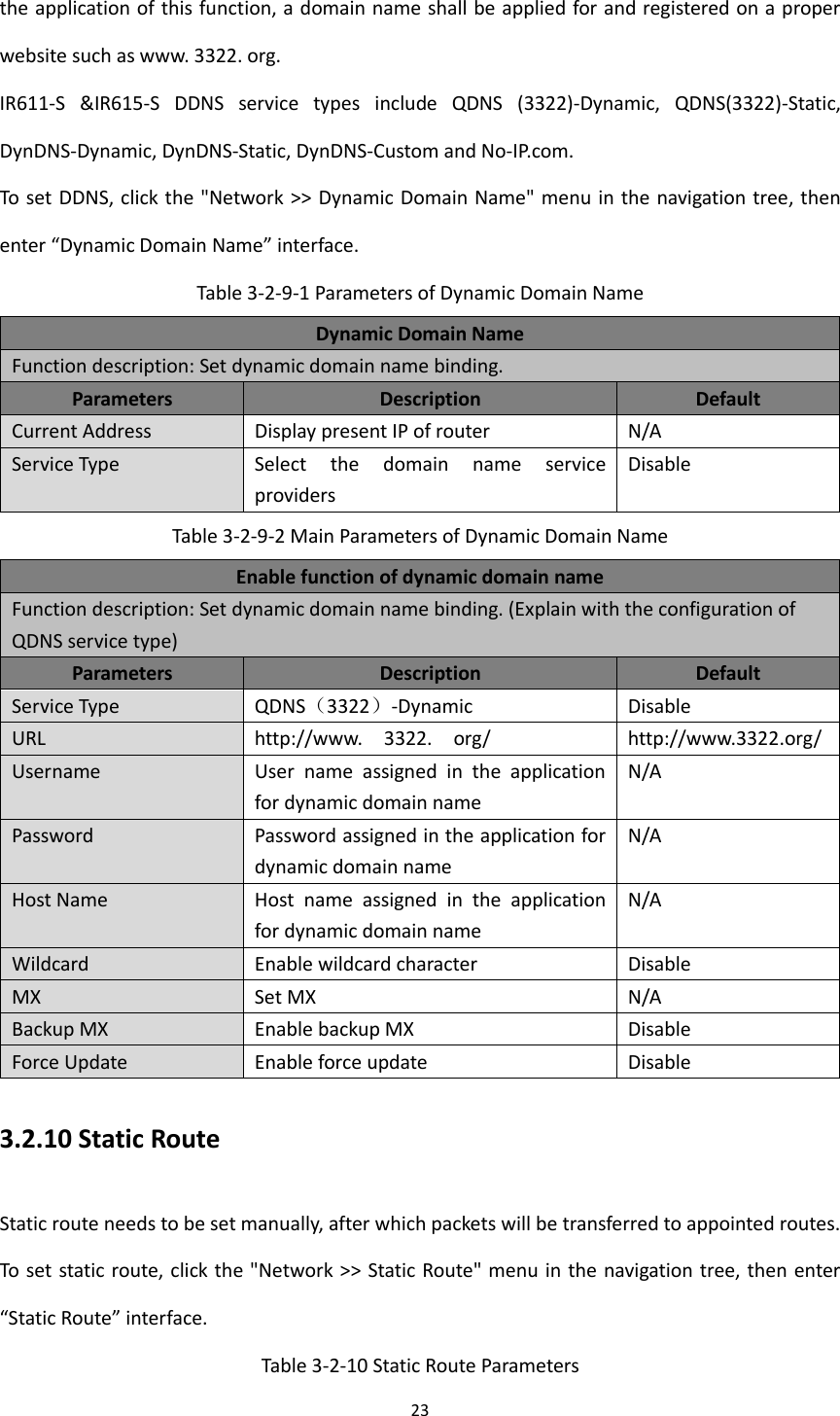
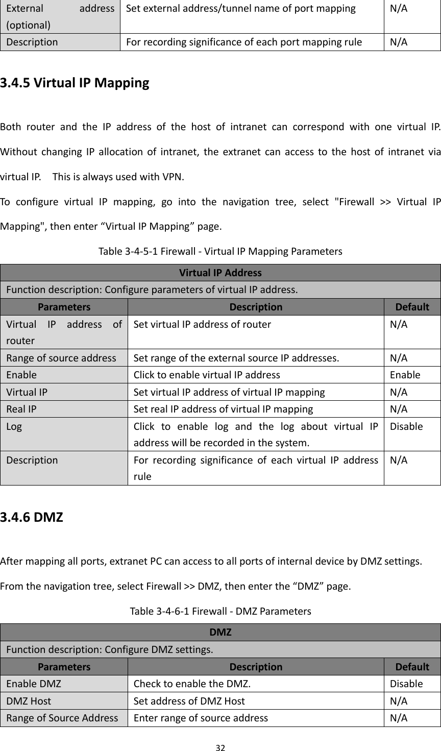
![2 Preface This user manual will guide you on installing and configuring InHand IR6XX-S industrial router. Audience This manual is for: Network Planner Field technical support Network administrators Conventions This manual uses the following conventions: Conventions Indication <> Content in angle brackets “<>” indicates a button name. For example, the <OK> button. “” “” indicates a window name or menu name. For example, the pop-up window “New User.” >> A multi-level menu is separated by the double brackets “>>.” For example, the multi-level menu File >> New >>Folder indicates the menu item [Folder] under the sub-menu [New], which is under the menu [File]. Means reader be careful. Improper action may result in loss of data or device damage. Notes contain detailed descriptions and helpful suggestions.](https://usermanual.wiki/Beijing-InHand-Networks-Technology/IR6X5/User-Guide-3201749-Page-3.png)
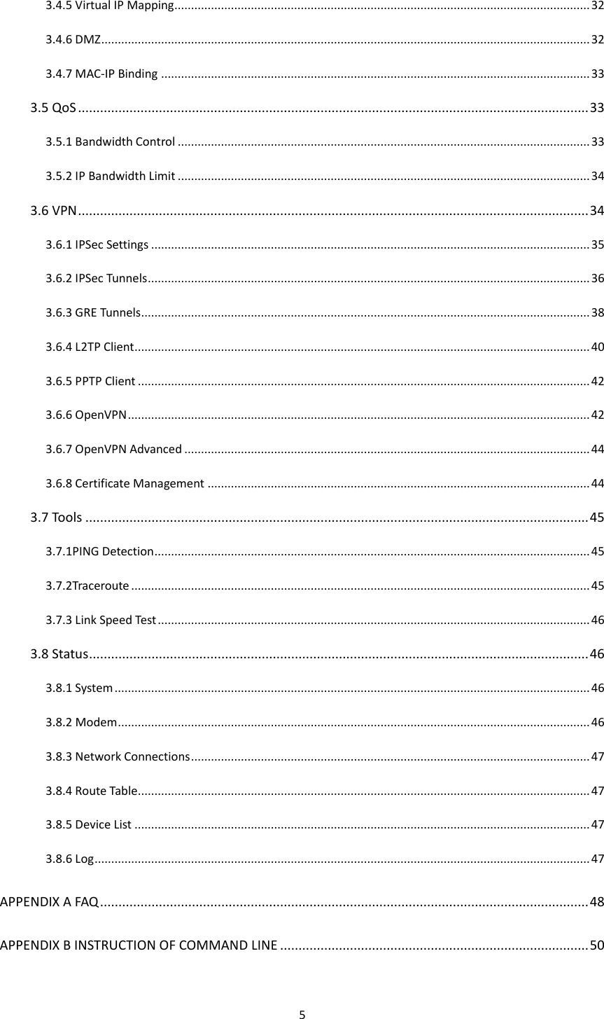
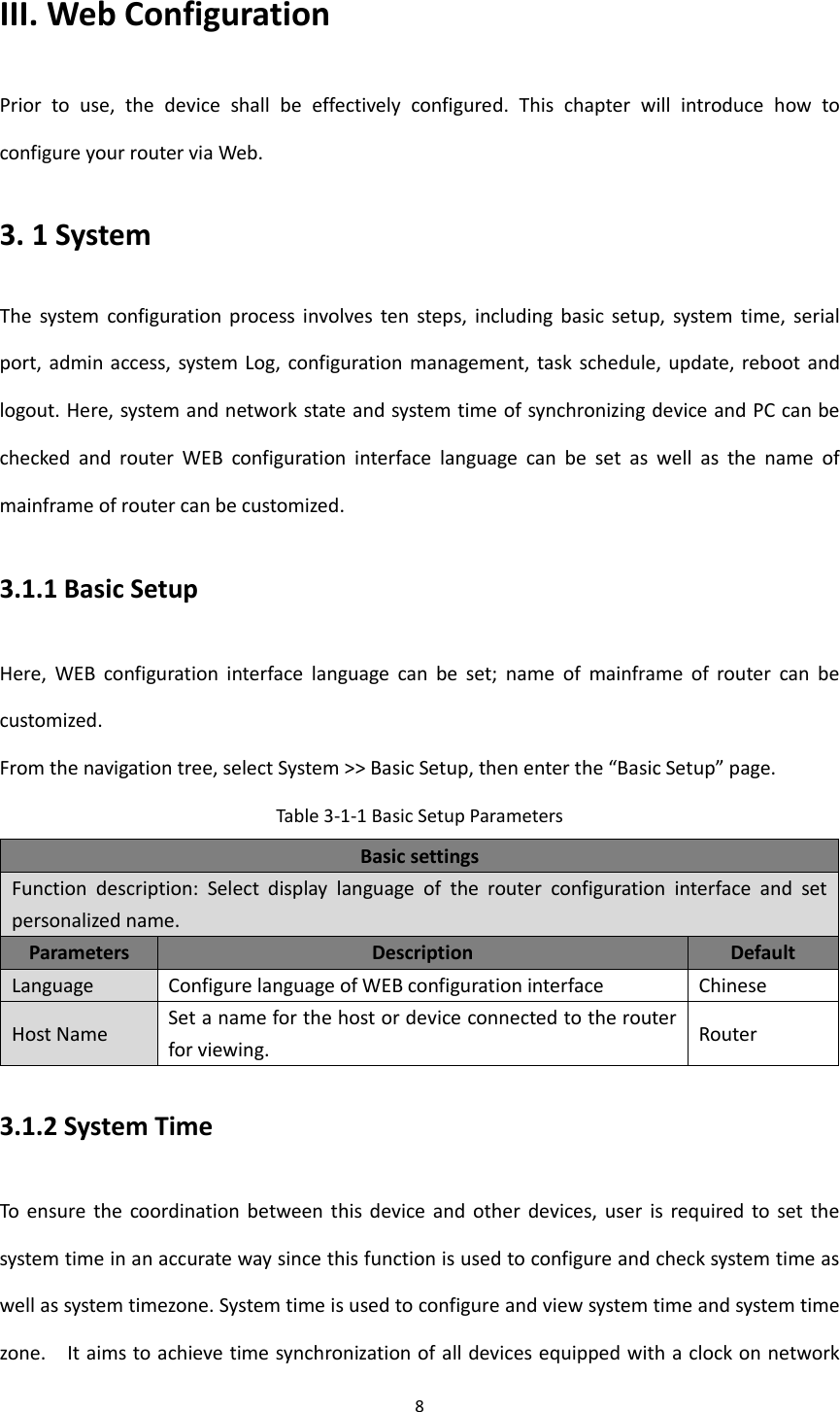
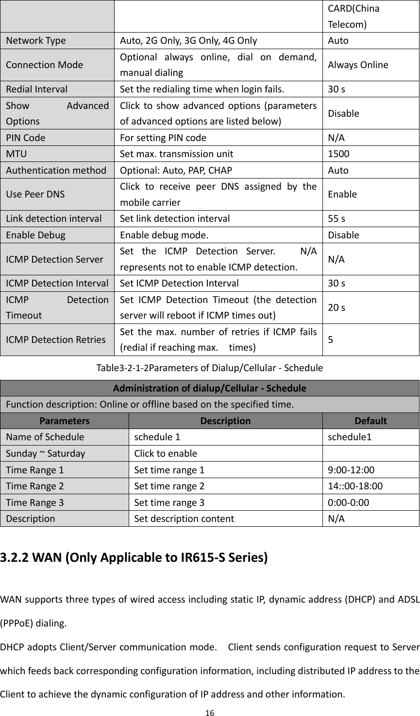
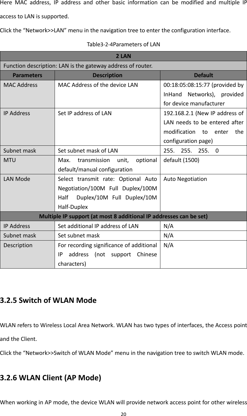
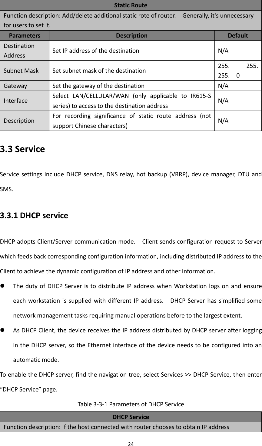
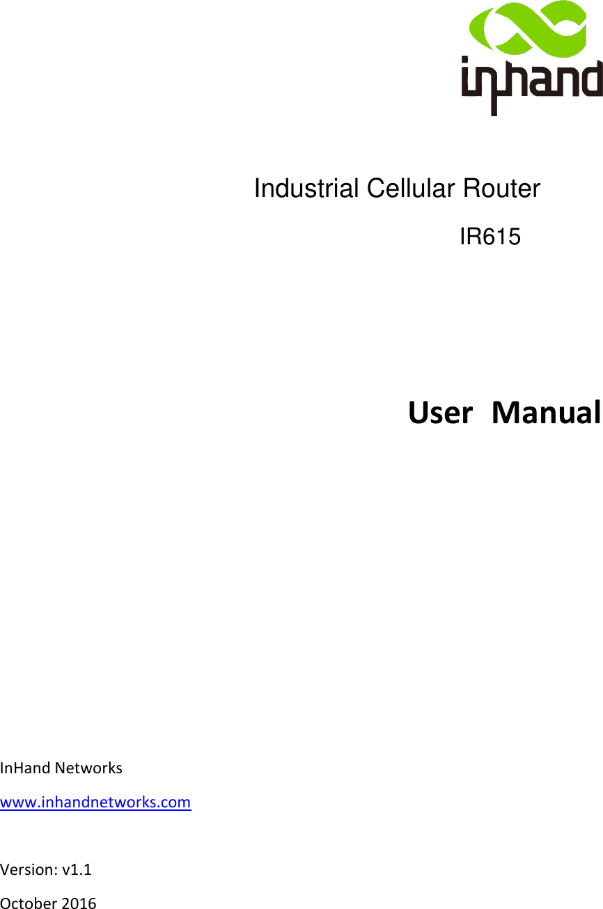
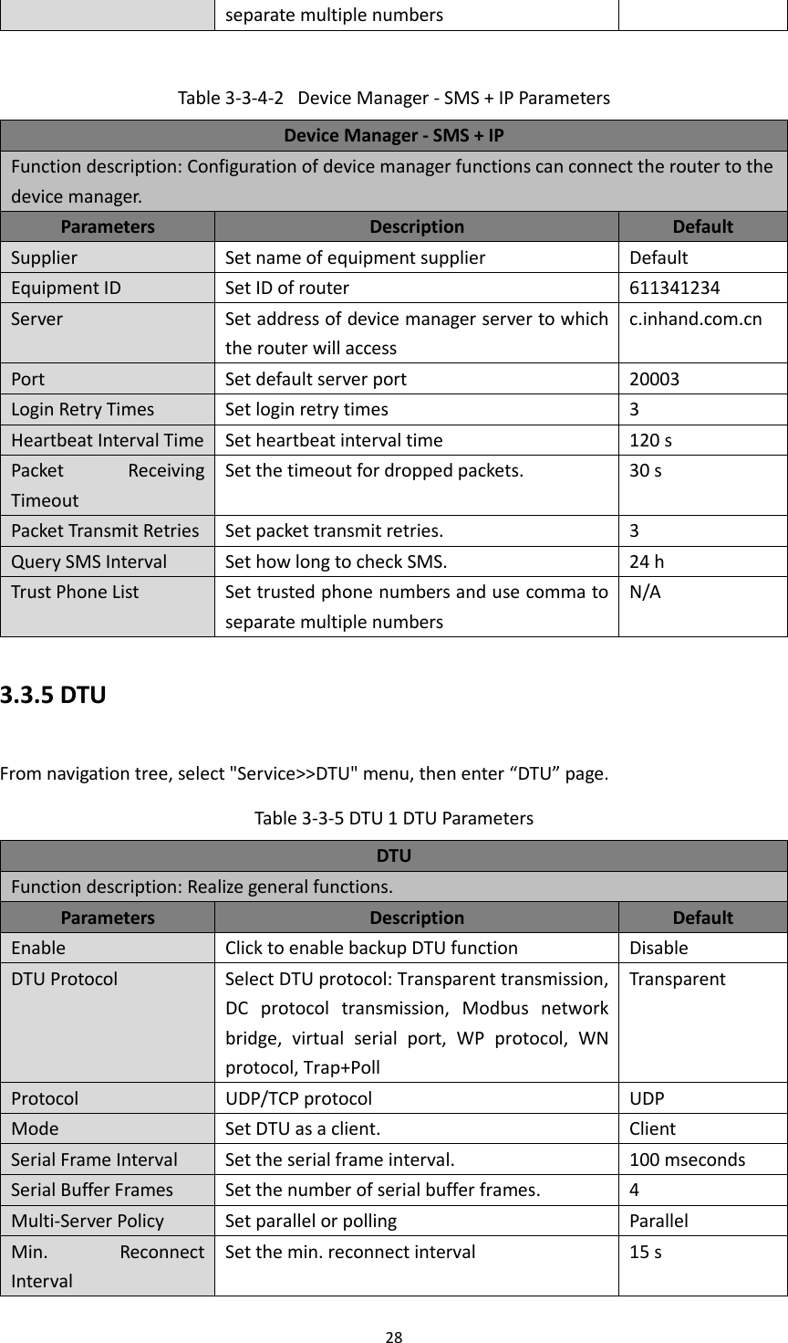
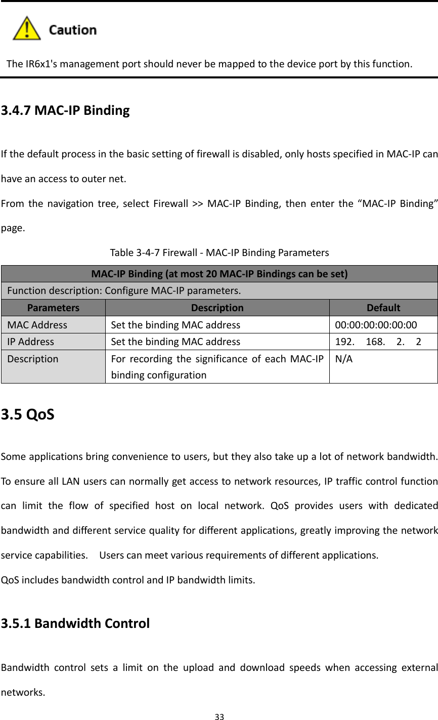
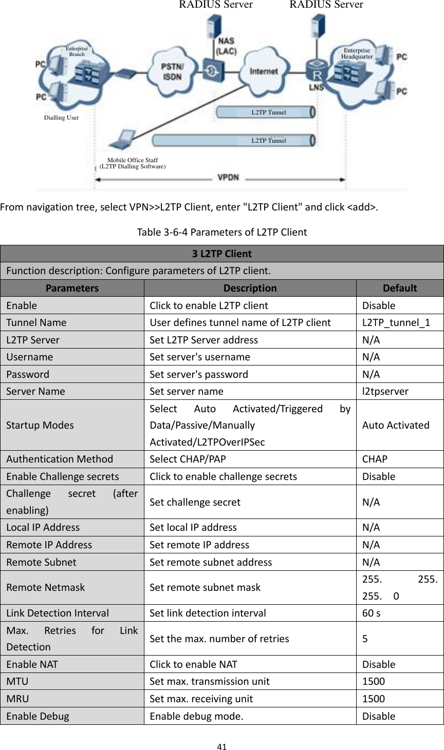
![25 automatically, then such service must be activated. Static designation of DHCH allocation could help certain host to obtain specified IP address. Parameters Description Default Enable DHCP Enable DHCP service and dynamically allocate IP address Enable IP Pool Starting Address Set starting IP address of dynamic allocation 192. 168. 2. 2 IP Pool Ending Address Set ending IP address of dynamic allocation 192. 168. 2. 100 Lease Set lease of IP allocated dynamically 60 minutes DNS Set DNS Server 192. 168. 2. 1 Windows Name Server Set windows name server. N/A Static designation of DHCH allocation (at most 20 DHCPs designated statically can be set) MAC Address Set a statically specified DHCP’s MAC address (different from other MACs to avoid confliction) N/A IP Address Set a statically specified IP address 192. 168. 2. 2 Host Set the hostname. N/A 3.3.2 DNS Relay The device, as a DNS Agent, relays DNS request and response message between DNS Client and DNS Server to carry out domain name resolution in lieu of DNS Client. From navigation tree, select "Network >>DNS Relay" menu, then enter “DNS Relay” page. Table 3-3-2 DNS Transfer Parameters DNS Relay service Function description: If the host connected with router chooses to obtain DNS address automatically, then such service must be activated. Parameters Description Default Enable DNS Relay service Click to enable DNS service Enable (DNS will be available when DHCP service is enabled.) Designate [IP address <=> domain name] pair (20 IP address <=> domain name pairs can be designated) IP Address Set IP address of designated IP address <=> domain name N/A Host Domain Name N/A Description For recording significance of IP address <=> domain name N/A](https://usermanual.wiki/Beijing-InHand-Networks-Technology/IR6X5/User-Guide-3201749-Page-31.png)
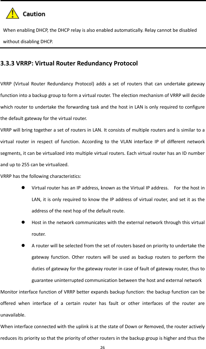
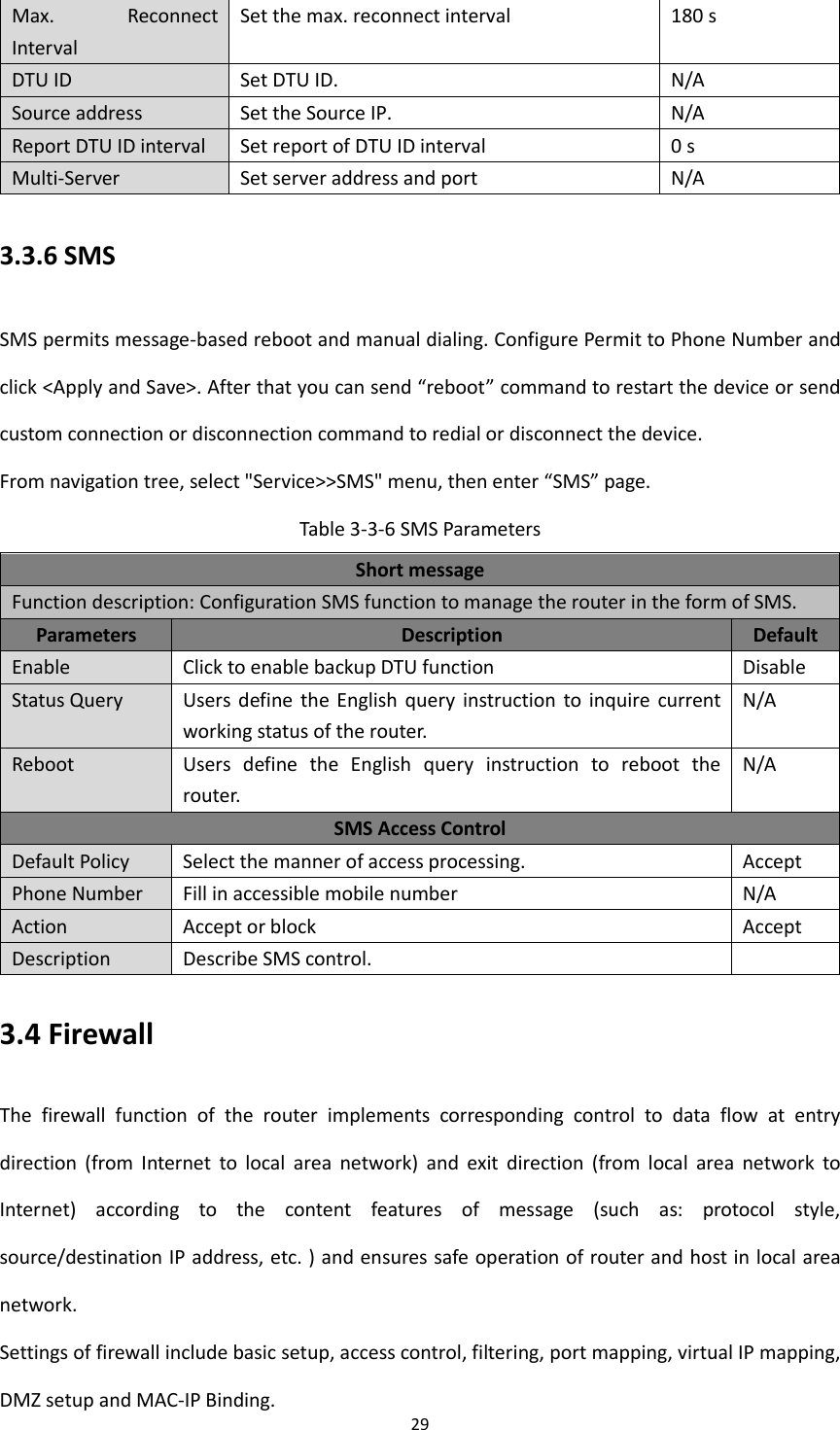
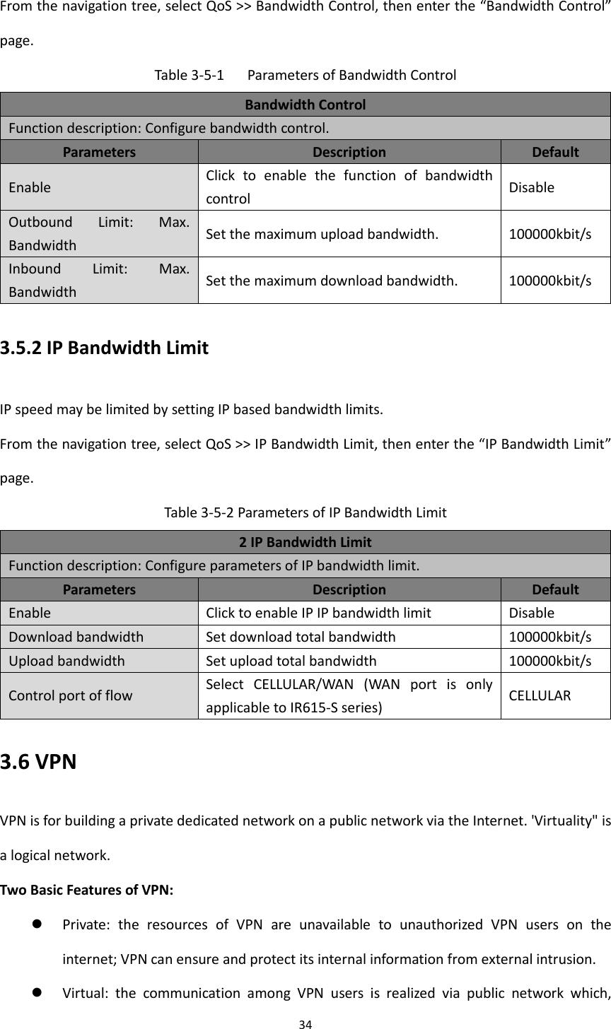
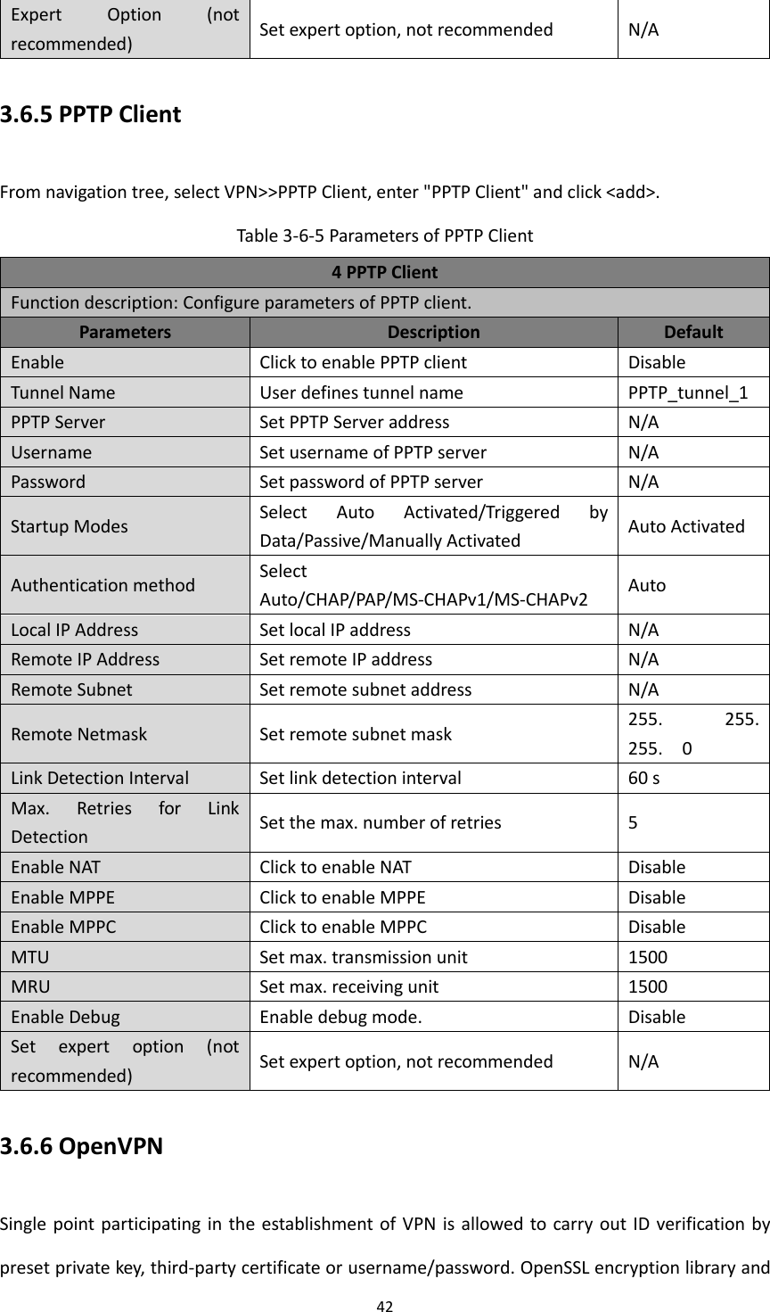
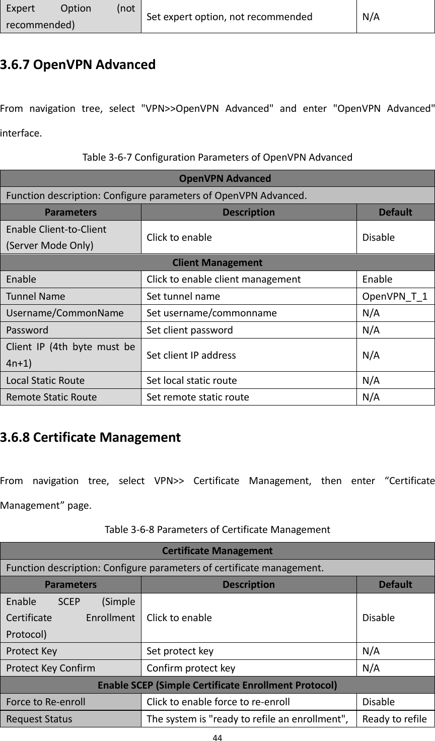

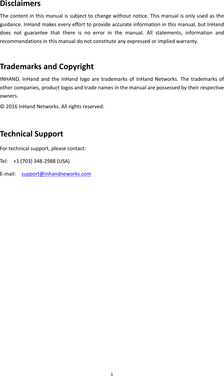
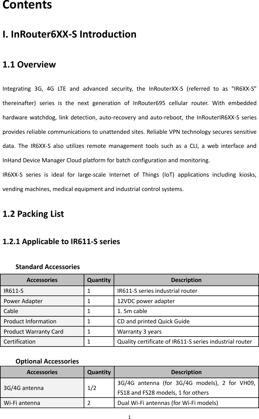
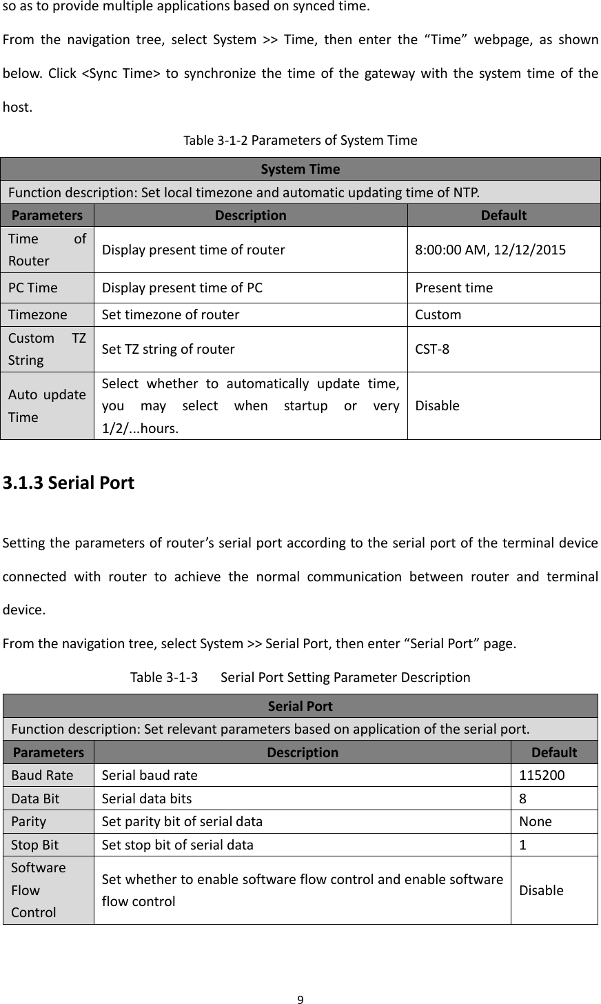
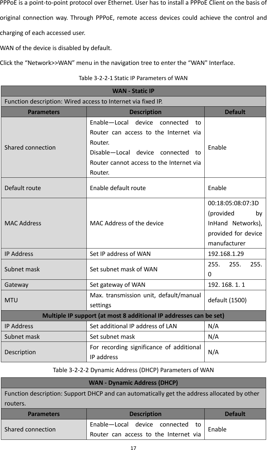
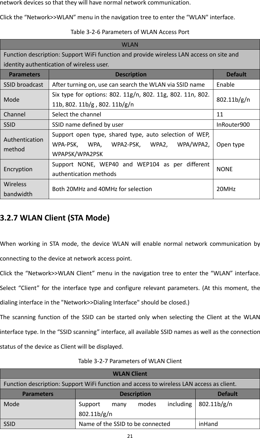
![50 settings. Appendix B Instruction of Command Line 1Help Command Help command can be obtained after entering help or “?” into console, “?” can be entered at any time during the process of command input to obtain the current command or help from command parameters, and command or parameters can be automatically complemented in case of only command or command parameter. 1.1 Help [Command] Help [<cmd>] [Function] Get help from command. [View] All views [Parameter] <cmd> command name [Example] Enter: help Get the list of all current available command. enter: help show Display all the parameters of show command and using instructions thereof. 2View Switchover Command 2.1Enable [Command] Enable [15 [<password>]] [Function] Switchover to privileged user level. [View] Ordinary user view. [Parameter]15 User right limit level, only supports right limit 15 (super users) at current. <password> Password corresponded to privileged user limit level, hint of password](https://usermanual.wiki/Beijing-InHand-Networks-Technology/IR6X5/User-Guide-3201749-Page-56.png)
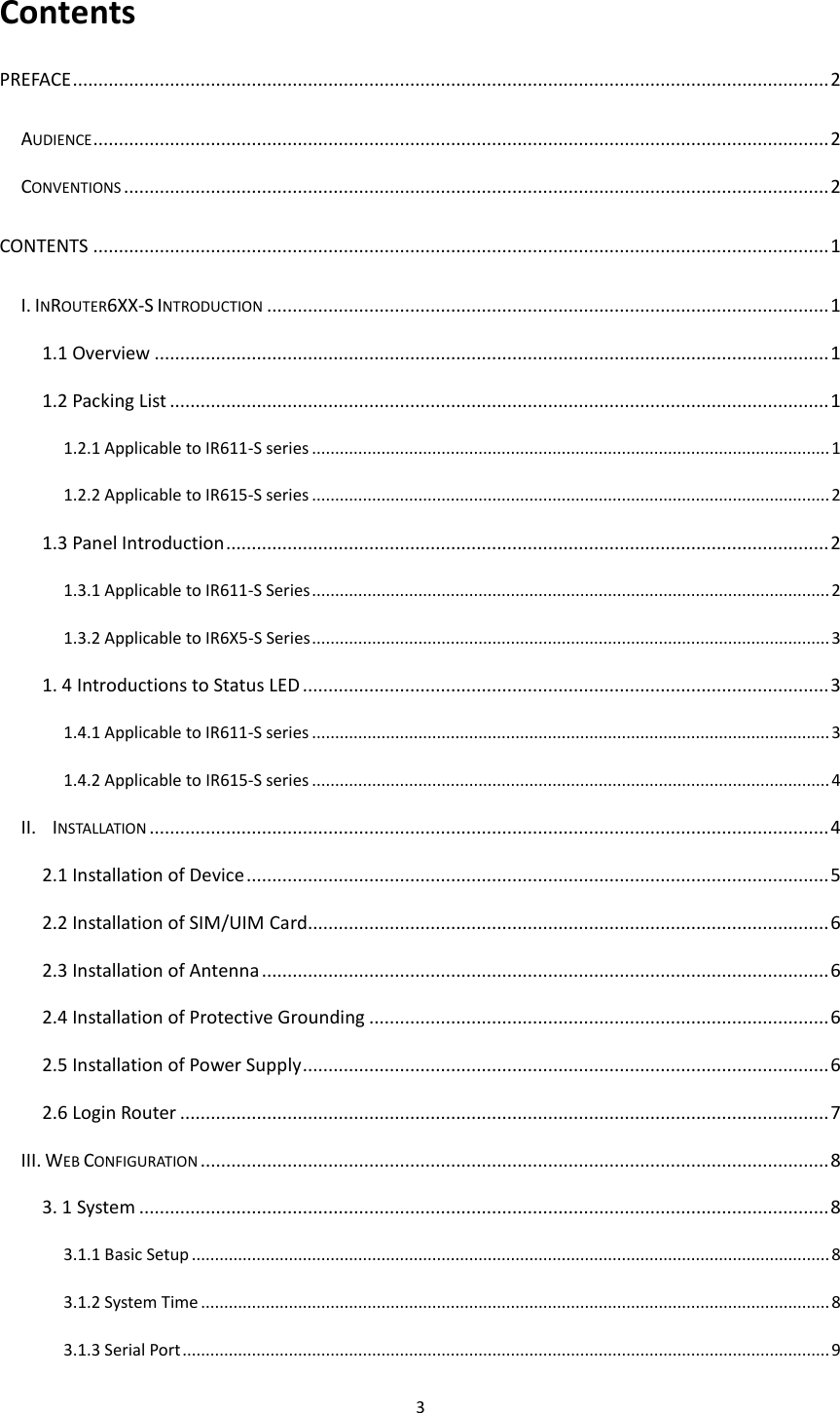
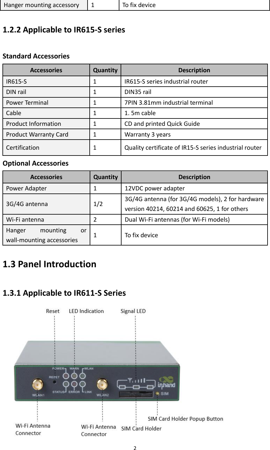
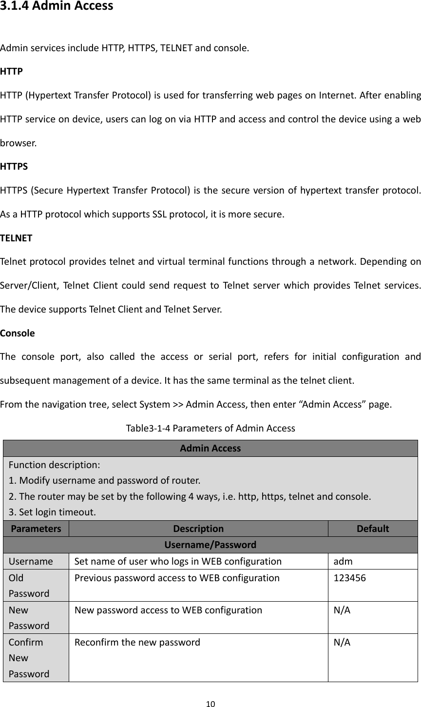
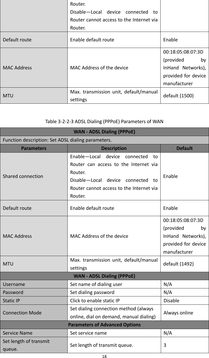
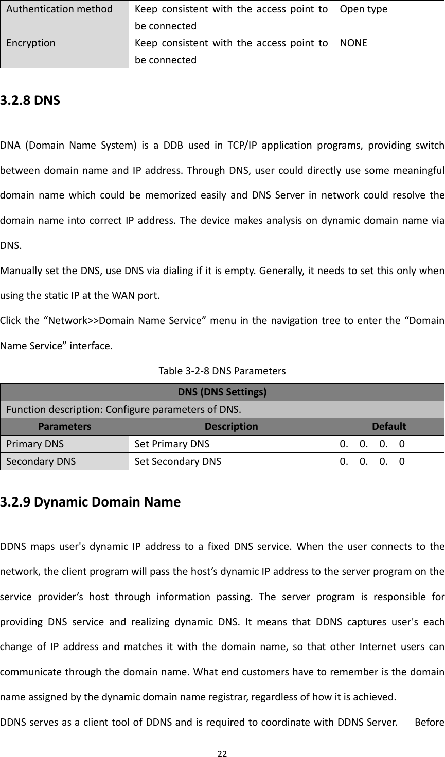
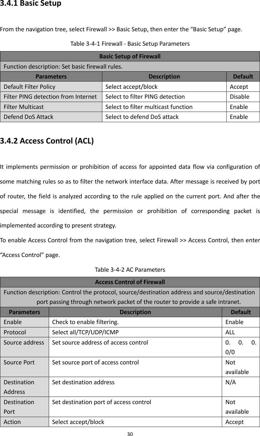
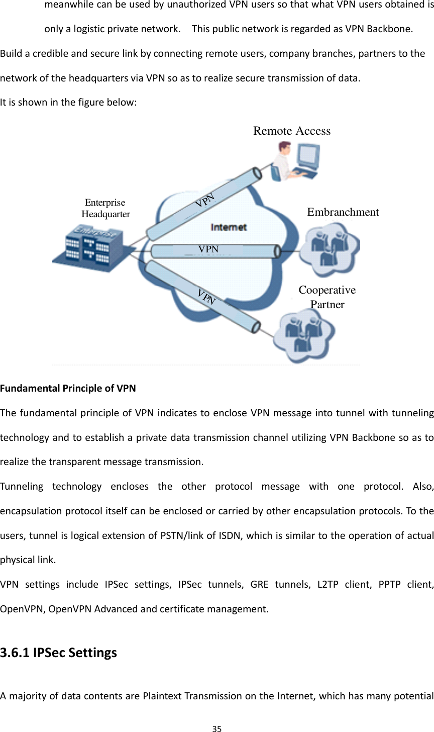
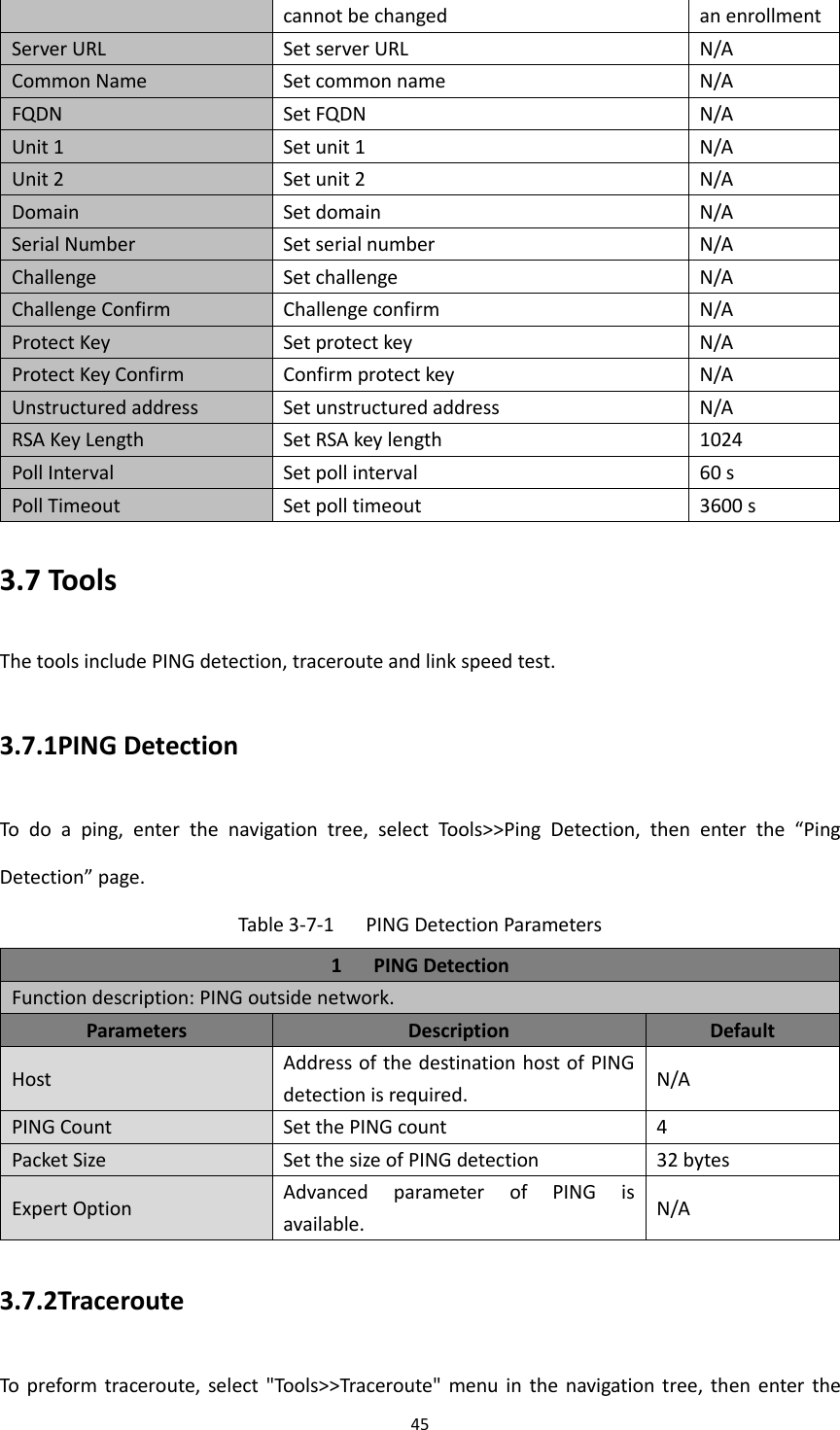
![51 inputting will be given in case of no entering. [Example] Enter exit in ordinary user view: enable 123456 Switchover to super users and the password 123456. 2.2 Disable [Command] Disable [Function] Exit the privileged user level. [View] Super user view, configure view [Parameter] No [Example] Enter in super user view: disable Return to ordinary user view. 2. 3 End and ! [Command] End or ! [Function] Exit the current view and return to the last view. [View] Configure view. [Parameter] No [Example] Enter in configured view: end Return to super user view. 2. 4 Exit [Command] Exit [Function] Exit the current view and return to the last view (exit console in case that it is ordinary user) [View] All views [Parameter] No [Example]](https://usermanual.wiki/Beijing-InHand-Networks-Technology/IR6X5/User-Guide-3201749-Page-57.png)
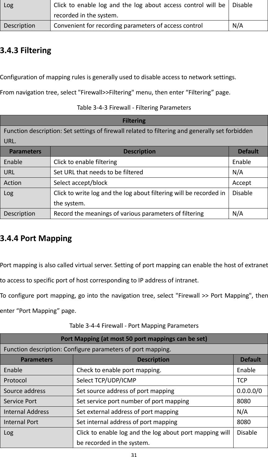
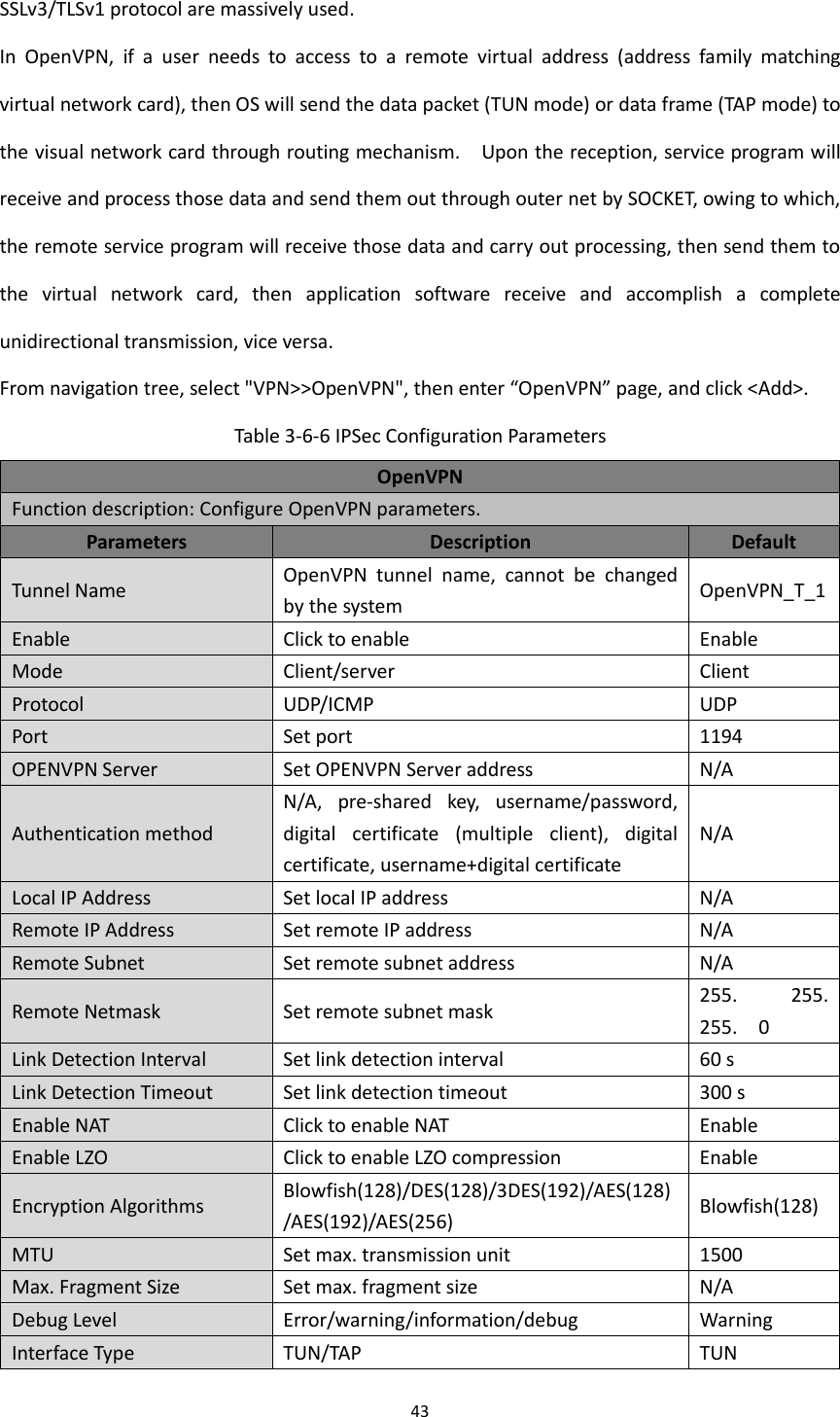
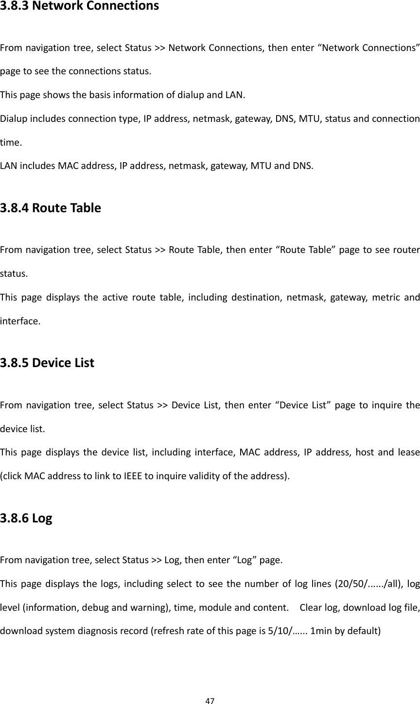
![52 Enter in configured view: exit Return to super user view. enter exit in ordinary user view: exit Exit console. 3 Check system state command 3. 1 Show version [Command] Show version [Function] Display the type and version of software of router [View] All views [Parameter] No [Example] Enter: show version Display the following information: Type : display the current factory type of equipment Serial number : display the current factory serial number of equipment Description : www.inhand.com.cn Current version : display the current version of equipment Current version of Bootloader: display the current version of equipment 3. 2 Show system [Command] Show system [Function] Display the information of router system [View] All views [Parameter] No [Example] Enter: show system Display the following information:](https://usermanual.wiki/Beijing-InHand-Networks-Technology/IR6X5/User-Guide-3201749-Page-58.png)
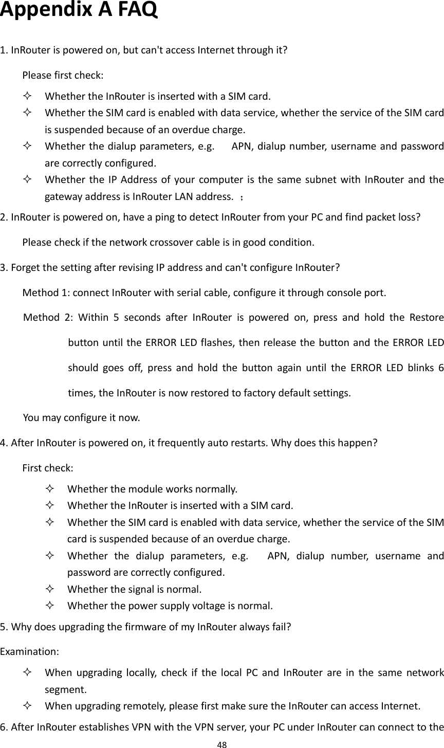
![53 Example: 00:00:38 up 0 min, load average: 0.00, 0.00, 0.00 3. 3 show clock [Command] Show clock [Function] Display the system time of router [View] All views [Parameter] No [Example] Enter: show clock Display the following information: For example Sat Jan 1 00:01:28 UTC 2000 3. 4 Show modem [Command] Show modem [Function] Display the MODEM state of router [View] All views [Parameter] No [Example] Enter: show modem Display the following information: Modem type state manufacturer Product name signal level register state IMSI number Network Type 3. 5 Show log [Command] Show log [lines <n>]](https://usermanual.wiki/Beijing-InHand-Networks-Technology/IR6X5/User-Guide-3201749-Page-59.png)
![54 [Function] Display the log of router system and display the latest 100 logs in default. [View] All views [Parameter] Lines <n> limits the log numbers displayed, wherein, n indicates the latest n logs in case that it is positive integer and indicates the earliest n logs in case that it is negative integer and indicates all the logs in case that it is 0. [Example] Enter: show log Display the latest 100 log records. 3. 6 Show users [Command] Show users [Function] Display the user list of router. [View] All views [Parameter] No [Example] Enter: show users Displayed user list of system is as follows: User: ------------------------------------------------- * adm ------ Wherein, user marked with * is super user. 3. 7 Show startup-config [Command] Show startup-config [Function] Display the starting device of router. [View] Super user view and configuration view [Parameter] No [Example]](https://usermanual.wiki/Beijing-InHand-Networks-Technology/IR6X5/User-Guide-3201749-Page-60.png)
![55 Enter: show startup-config Display the starting configuration of system. 3. 8 Show running-config [Command] Show running-config [Function] Display the operational configuration of router [View] Super user view and configuration view [Parameter] No [Example] Enter: show startup-config Display the operational configuration of system. 4 Check Network Status Command 4. 1 Show interface [Command] Show interface [Function] Display the information of port state of router [View] All views [Parameter] No [Example] Enter: show interface Display the state of all ports. 4. 2 Show ip [Command] Show ip [Function] Display the information of port state of router [View] All views [Parameter] No [Example] Enter: Show ip](https://usermanual.wiki/Beijing-InHand-Networks-Technology/IR6X5/User-Guide-3201749-Page-61.png)
![56 Display system ip status 4. 3 Show route [Command] Show route [Function] Display the routing list of router [View] All views [Parameter] No [Example] enter: show route Display the routing list of system 4. 4 Show arp [Command] Show arp [Function] Display the ARP list of router [View] All views [Parameter] No [Example] Enter: show arp Display the ARP list of system 5 Internet Testing Command Router has provided ping , telnet and traceroute for Internet testing. 5. 1 Ping [Command] Ping <hostname> [count <n>] [size <n>] [source <ip>] [Function] Apply ICMP testing for appointed mainframe. [View] All views [Parameter] <hostname> tests the address or domain name of mainframe. count <n> testing times size <n> tests the size of data package (byte) source <ip> IP address of appointed testing](https://usermanual.wiki/Beijing-InHand-Networks-Technology/IR6X5/User-Guide-3201749-Page-62.png)
![57 [Example] Enter: ping www.g.cn Test www. g. cn and display the testing results 5. 2 Telnet [Command] Telnet <hostname> [<port>] [source <ip>] [Function] Telnet logs in the appointed mainframe [View] All views [Parameter] <hostname> in need of the address or domain name of mainframe logged in. <port>telnet port source <ip> appoints the IP address of telnet logged in. [Example] Enter: telnet 192.168.2.2 telnet logs in 192. 168. 2. 2 5. 3 Traceroute [Command] Traceroute <hostname> [maxhops <n>] [timeout <n>] [Function] Test the acting routing of appointed mainframe. [View] All views [Parameter] <hostname> tests the address or domain name of mainframe. maxhops <n> tests the maximum routing jumps timeout <n> timeout of each jumping testing (sec) [Example] Enter: traceroute www.g.cn Apply the routing of www. g. cn and display the testing results. 6 Configuration Command In super user view, router can use configure command to switch it over configure view for](https://usermanual.wiki/Beijing-InHand-Networks-Technology/IR6X5/User-Guide-3201749-Page-63.png)
![58 management. Some setting command can support no and default, wherein, no indicates the setting of canceling some parameter and default indicates the recovery of default setting of some parameter. 6. 1 Configure [Command] Configure terminal [Function] Switchover to configuration view and input the equipment at the terminal end. [View] Super user view [Parameter] No [Example] Enter in super user view: configure terminal Switchover to configuration view. 6. 2 Hostname [Command] Hostname [<hostname>] default hostname [Function] Display or set the mainframe name of router. [View] Configure view. [Parameter] <hostname> new mainframe name [Example] Enter in configured view: hostname Display the mainframe name of router. Enter in configured view: hostname MyRouter Set the mainframe name of router MyRouter. Enter in configured view: defaulthostname Recover the mainframe name of router to the factory setting. 6. 3 Clock timezone](https://usermanual.wiki/Beijing-InHand-Networks-Technology/IR6X5/User-Guide-3201749-Page-64.png)
![59 [Command] Clock timezone <timezone><n> default clock timezone [Function] Set the time zone information of the router. [View] Configure view. [Parameter] <timezone> timezone name, 3 capitalized English letters <n> time zone deviation value, -12~+12 [Example] Enter in configured view: clock timezone CST -8 The time zone of IG601is east eighth area and the name is CST (China's standard time). Enter in configured view: default clock timezone Recover the timezone of router to the factory setting. 6. 4 Clock set [Command] Clock set <YEAR/MONTH/DAY> [<HH:MM:SS>] [Function] Set the date and time of router. [View] Configure view. [Parameter] <YEAR/MONTH/DAY> date, format: Y-M-D <HH:MM:SS > time, format: H-M-S [Example] Enter in configured view: clock set 2009-10-5 10:01:02 The time of router set is 10:01:02 of Oct. 5th, 2009 morning. 6. 5 Ntp server [Command] ntp server <hostname> no ntp server default ntp server](https://usermanual.wiki/Beijing-InHand-Networks-Technology/IR6X5/User-Guide-3201749-Page-65.png)
![60 [Function] Set the customer end of Internet time server [View] Configure view. [Parameter] <hostname> address or domain name of mainframe of time server [Example] Enter in configured view: ntp server pool.ntp.org Set the address of Internet time server pool. ntp. org. Enter in configured view: no ntp server Disable the router to get system time via network. Enter in configured view: default ntp server Recover the network time server of router to the factory setting. 6. 6 Config export [Command] Config export [Function] Export config [View] Configure view. [Parameter] No [Example] Enter in configured view: config export The current config. is exported. 6. 7 Config import [Command] Config import [Function] Import config [View] Configure view. [Parameter] No [Example] Enter in configured view: config import](https://usermanual.wiki/Beijing-InHand-Networks-Technology/IR6X5/User-Guide-3201749-Page-66.png)
![61 The config. is imported. 7 System Management Command 7. 1 Reboot [Command] Reboot [Function] System restarts. [View] Super user view and configuration view [Parameter] No [Example] Enter in super user view: reboot System restarts. 7. 2 Enable username [Command] Enable password [<name>] [Function] Modify the username of super user. [View] Configure view. [Parameter] <name> new super user username [Example] Enter in configured view: enable username admin The username of super user is changed to admin. 7. 3 Enable password [Command] Enable password [<password>] [Function] Modify the password of super user. [View] Configure view. [Parameter] <password> new super user password [Example] Enter in configured view: enable password](https://usermanual.wiki/Beijing-InHand-Networks-Technology/IR6X5/User-Guide-3201749-Page-67.png)
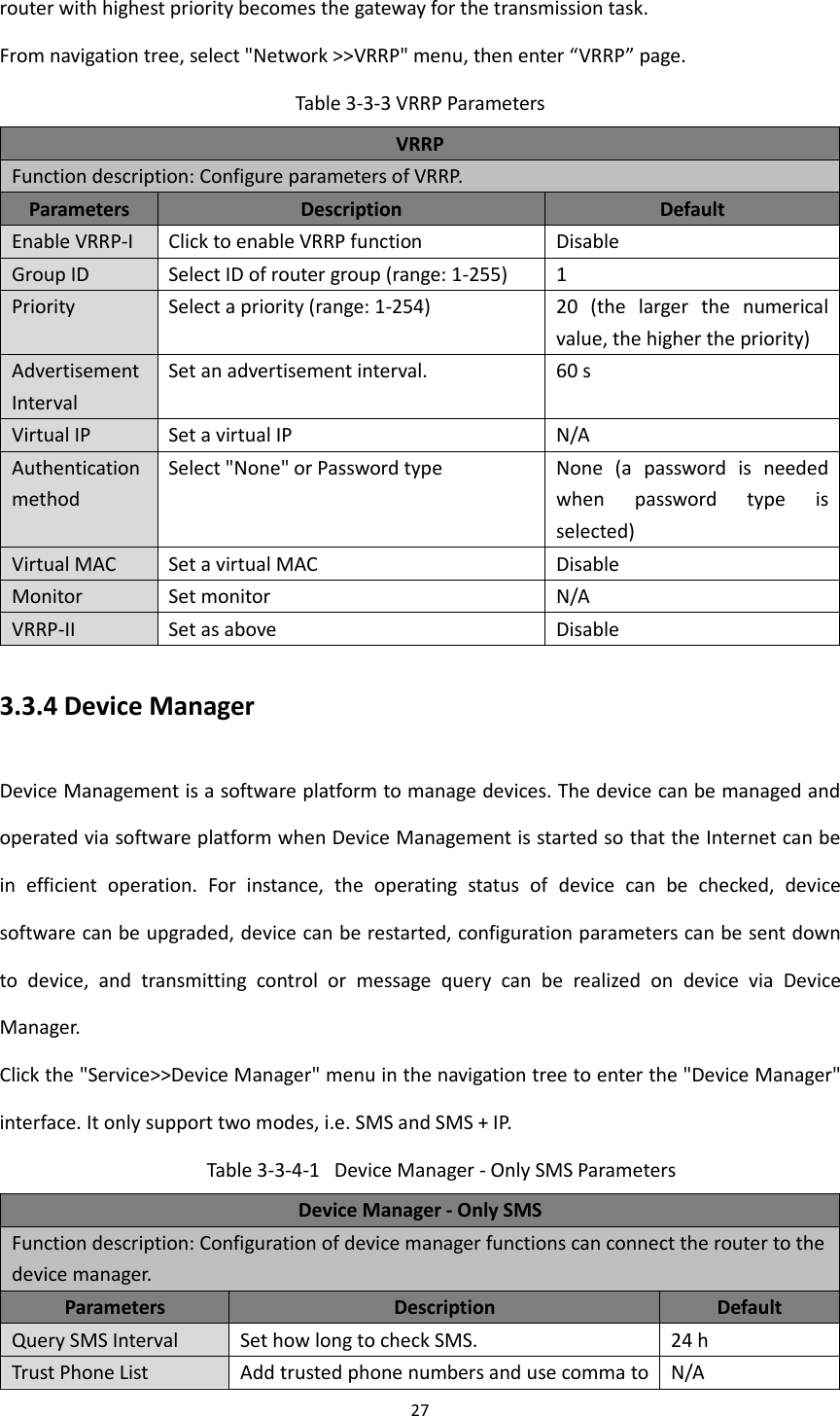
![62 Enter password according to the hint. 7. 4 Username [Command] Username <name> [password [<password>]] no username <name> default username [Function] Set user name, password [View] Configure view. [Parameter] No [Example] Enter in configured view: username abc password 123 Add an ordinary user, the name is abc and the password is 123. Enter in configured view: no username abc Delete the ordinary user with the name of abc. Enter in configured view: default username Delete all the ordinary users.](https://usermanual.wiki/Beijing-InHand-Networks-Technology/IR6X5/User-Guide-3201749-Page-68.png)