Beijing InHand Networks Technology IR6X5 Industrial Cellular Router User Manual
Beijing InHand Networks Technology Co., Ltd. Industrial Cellular Router Users Manual
Users Manual


1
Disclaimers
The content in this manual is subject to change without notice. This manual is only used as the
guidance. InHand makes every effort to provide accurate information in this manual, but InHand
does not guarantee that there is no error in the manual. All statements, information and
recommendations in this manual do not constitute any expressed or implied warranty.
Trademarks and Copyright
INHAND, InHand and the InHand logo are trademarks of InHand Networks. The trademarks of
other companies, product logos and trade names in the manual are possessed by their respective
owners.
© 2016 InHand Networks. All rights reserved.
Technical Support
For technical support, please contact:
Tel: +1 (703) 348-2988 (USA)
E-mail: support@inhandneworks.com
2
Preface
This user manual will guide you on installing and configuring InHand IR6XX-S industrial router.
Audience
This manual is for:
Network Planner
Field technical support
Network administrators
Conventions
This manual uses the following conventions:
Conventions
Indication
<>
Content in angle brackets “<>” indicates a button name. For example, the <OK>
button.
“”
“” indicates a window name or menu name. For example, the pop-up window
“New User.”
>>
A multi-level menu is separated by the double brackets “>>.” For example, the
multi-level menu File >> New >>Folder indicates the menu item [Folder] under
the sub-menu [New], which is under the menu [File].
Means reader be careful. Improper action may result in loss of data or device damage.
Notes contain detailed descriptions and helpful suggestions.
3
Contents
PREFACE .................................................................................................................................................... 2
AUDIENCE ................................................................................................................................................ 2
CONVENTIONS .......................................................................................................................................... 2
CONTENTS ................................................................................................................................................ 1
I. INROUTER6XX-S INTRODUCTION .............................................................................................................. 1
1.1 Overview .................................................................................................................................... 1
1.2 Packing List ................................................................................................................................. 1
1.2.1 Applicable to IR611-S series ................................................................................................................ 1
1.2.2 Applicable to IR615-S series ................................................................................................................ 2
1.3 Panel Introduction ...................................................................................................................... 2
1.3.1 Applicable to IR611-S Series ................................................................................................................ 2
1.3.2 Applicable to IR6X5-S Series ................................................................................................................ 3
1. 4 Introductions to Status LED ....................................................................................................... 3
1.4.1 Applicable to IR611-S series ................................................................................................................ 3
1.4.2 Applicable to IR615-S series ................................................................................................................ 4
II. INSTALLATION ..................................................................................................................................... 4
2.1 Installation of Device .................................................................................................................. 5
2.2 Installation of SIM/UIM Card...................................................................................................... 6
2.3 Installation of Antenna ............................................................................................................... 6
2.4 Installation of Protective Grounding .......................................................................................... 6
2.5 Installation of Power Supply ....................................................................................................... 6
2.6 Login Router ............................................................................................................................... 7
III. WEB CONFIGURATION ........................................................................................................................... 8
3. 1 System ....................................................................................................................................... 8
3.1.1 Basic Setup .......................................................................................................................................... 8
3.1.2 System Time ........................................................................................................................................ 8
3.1.3 Serial Port ............................................................................................................................................ 9
4
3.1.4 Admin Access .................................................................................................................................... 10
3.1.5 System Log ........................................................................................................................................ 11
3.1.6 Configuration Management .............................................................................................................. 12
3.1.7 Task Schedule .................................................................................................................................... 13
3.1.8 System Upgrading ............................................................................................................................. 13
3.1.9 Reboot ............................................................................................................................................... 13
3.1.10 Logout ............................................................................................................................................. 14
3. 2 Network ................................................................................................................................... 15
3.2.1 Dialup/Cellular Connection ............................................................................................................... 15
3.2.2 WAN (Only Applicable to IR615-S Series) .......................................................................................... 16
3.2.3 Link Backup ....................................................................................................................................... 19
3.2.4 LAN .................................................................................................................................................... 19
3.2.5 Switch of WLAN Mode ...................................................................................................................... 20
3.2.6 WLAN Client (AP Mode) .................................................................................................................... 20
3.2.7 WLAN Client (STA Mode) ................................................................................................................... 21
3.2.8 DNS.................................................................................................................................................... 22
3.2.9 Dynamic Domain Name..................................................................................................................... 22
3.2.10 Static Route ..................................................................................................................................... 23
3.3 Service ...................................................................................................................................... 24
3.3.1 DHCP service ..................................................................................................................................... 24
3.3.2 DNS Relay .......................................................................................................................................... 25
3.3.3 VRRP: Virtual Router Redundancy Protocol ...................................................................................... 26
3.3.4 Device Manager ................................................................................................................................ 27
3.3.5 DTU ................................................................................................................................................... 28
3.3.6 SMS ................................................................................................................................................... 29
3.4 Firewall ..................................................................................................................................... 29
3.4.1 Basic Setup ........................................................................................................................................ 30
3.4.2 Access Control (ACL) .......................................................................................................................... 30
3.4.3 Filtering ............................................................................................................................................. 31
3.4.4 Port Mapping .................................................................................................................................... 31
5
3.4.5 Virtual IP Mapping............................................................................................................................. 32
3.4.6 DMZ ................................................................................................................................................... 32
3.4.7 MAC-IP Binding ................................................................................................................................. 33
3.5 QoS ........................................................................................................................................... 33
3.5.1 Bandwidth Control ............................................................................................................................ 33
3.5.2 IP Bandwidth Limit ............................................................................................................................ 34
3.6 VPN ........................................................................................................................................... 34
3.6.1 IPSec Settings .................................................................................................................................... 35
3.6.2 IPSec Tunnels ..................................................................................................................................... 36
3.6.3 GRE Tunnels ....................................................................................................................................... 38
3.6.4 L2TP Client ......................................................................................................................................... 40
3.6.5 PPTP Client ........................................................................................................................................ 42
3.6.6 OpenVPN ........................................................................................................................................... 42
3.6.7 OpenVPN Advanced .......................................................................................................................... 44
3.6.8 Certificate Management ................................................................................................................... 44
3.7 Tools ......................................................................................................................................... 45
3.7.1PING Detection ................................................................................................................................... 45
3.7.2Traceroute .......................................................................................................................................... 45
3.7.3 Link Speed Test .................................................................................................................................. 46
3.8 Status ........................................................................................................................................ 46
3.8.1 System ............................................................................................................................................... 46
3.8.2 Modem .............................................................................................................................................. 46
3.8.3 Network Connections ........................................................................................................................ 47
3.8.4 Route Table........................................................................................................................................ 47
3.8.5 Device List ......................................................................................................................................... 47
3.8.6 Log ..................................................................................................................................................... 47
APPENDIX A FAQ ..................................................................................................................................... 48
APPENDIX B INSTRUCTION OF COMMAND LINE .................................................................................... 50

1
Contents
I. InRouter6XX-S Introduction
1.1 Overview
Integrating 3G, 4G LTE and advanced security, the InRouterXX-S (referred to as “IR6XX-S”
thereinafter) series is the next generation of InRouter695 cellular router. With embedded
hardware watchdog, link detection, auto-recovery and auto-reboot, the InRouterIR6XX-S series
provides reliable communications to unattended sites. Reliable VPN technology secures sensitive
data. The IR6XX-S also utilizes remote management tools such as a CLI, a web interface and
InHand Device Manager Cloud platform for batch configuration and monitoring.
IR6XX-S series is ideal for large-scale Internet of Things (IoT) applications including kiosks,
vending machines, medical equipment and industrial control systems.
1.2 Packing List
1.2.1 Applicable to IR611-S series
Standard Accessories
Accessories
Quantity
Description
IR611-S
1
IR611-S series industrial router
Power Adapter
1
12VDC power adapter
Cable
1
1. 5m cable
Product Information
1
CD and printed Quick Guide
Product Warranty Card
1
Warranty 3 years
Certification
1
Quality certificate of IR611-S series industrial router
Optional Accessories
Accessories
Quantity
Description
3G/4G antenna
1/2
3G/4G antenna (for 3G/4G models), 2 for VH09,
FS18 and FS28 models, 1 for others
Wi-Fi antenna
2
Dual Wi-Fi antennas (for Wi-Fi models)
2
Hanger mounting accessory
1
To fix device
1.2.2 Applicable to IR615-S series
Standard Accessories
Accessories
Quantity
Description
IR615-S
1
IR615-S series industrial router
DIN rail
1
DIN35 rail
Power Terminal
1
7PIN 3.81mm industrial terminal
Cable
1
1. 5m cable
Product Information
1
CD and printed Quick Guide
Product Warranty Card
1
Warranty 3 years
Certification
1
Quality certificate of IR15-S series industrial router
Optional Accessories
Accessories
Quantity
Description
Power Adapter
1
12VDC power adapter
3G/4G antenna
1/2
3G/4G antenna (for 3G/4G models), 2 for hardware
version 40214, 60214 and 60625, 1 for others
Wi-Fi antenna
2
Dual Wi-Fi antennas (for Wi-Fi models)
Hanger mounting or
wall-mounting accessories
1
To fix device
1.3 Panel Introduction
1.3.1 Applicable to IR611-S Series
3
1.3.2 Applicable to IR6X5-S Series
IR6XX-S series has a variety of panel appearances, but all of the installation methods are the
same. The specific panel condition should be subject to the real object.
1. 4 Introductions to Status LED
1.4.1 Applicable to IR611-S series
POWER
STATUS
WARN
ERROR
LINK
Description
(Red)
(Green)
(Yellow)
(Red)
(Yellow)
On
Off
Off
Off
On
Powered On
On
Blinking
On
Off
Blinking
Powered on succeed
On
Blinking
On
Off
Blinking
Dialing
On
Blinking
Off
Off
Blinking
Dialing succeed
On
Blinking
Blinking
Blinking
Blinking
Upgrading
On
Blinking
On
Blinking
On
Reset Succeed
Signal status LED and description:
Green LED 1
Green LED 2
Green LED 3
Description
Off
Off
Off
No signal detected
On
Off
Off
Signal strength 1-9 (Signal strength is weak,
please check antenna and the signal strength of

4
current location)
On
On
Off
Signal strength 10-19 (signal strength is basically
normal, and equipment can be used under
normal conditions)
On
On
On
Signal strength 20-31 (signal strong)
WLAN LED and description:
WLAN Green LED
Description
On
Enable WLAN
Off
Disable WLAN
Blinking
Reset Succeed
1.4.2 Applicable to IR615-S series
POWER
STATUS
WARN
ERROR
Description
(Red)
(Green)
(Yellow)
(Red)
On
Off
Off
Off
Powered On
On
Blinking
On
Off
Powered on succeed
On
Blinking
On
Off
Dialing
On
Blinking
Off
Off
Dialing succeed
On
Blinking
Blinking
Blinking
Upgrading
On
Blinking
On
Blinking
Reset Succeed
Signal status LED and description:
Green LED 1
Green LED 2
Green LED 3
Description
Off
Off
Off
No signal detected
On
Off
Off
Signal strength 1-9 (Signal strength is weak,
please check antenna and the signal strength of
current location)
On
On
Off
Signal strength 10-19 (signal strength is basically
normal, and equipment can be used under
normal conditions)
On
On
On
Signal strength 20-31 (signal strong)
WLAN LED and description:
WLAN Green LED
Description
On
Enable WLAN
Off
Disable WLAN
Blinking
Reset Succeed
II. Installation

5
2.1 Installation of Device
Precautions:
Please be sure there is 3G/4G network coverage and there is no shield on site. 220V AC or
9~26VDC shall be provided on site. First installation shall be done under direction of the
engineer recognized by InHand Networks.
1 PC
OS: Windows 2000, Windows NT, Windows XP, Windows 7
CPU: Above PII 233
Memory: Above 32M
Hard disk: Above 6.4G
Serial port: At least one
Ethernet port: At least one (10M/100M)
IE version: Above 5.0
Resolution ratio: Above 640*480
1 SIM card:
Ensure the card is enabled with data service and its service is not suspended
because of an overdue charge.
Power supply:
220V AC: Alternatively used with the product with DC power
9~26V DC: Ripple voltage < 100 mV
Fixation:
Please place InRouter level and have it installed in an environment with small
vibrational frequency.
The device shall be installed and operated when powered off!

6
2.2 Installation of SIM/UIM Card
IR6XX-S series apply pop-up card holder. Press the yellow button on the right of the card holder
and the card holder will pop up. Then, install the SIM/UIM card and press the card holder back to
the card slot.
2.3 Installation of Antenna
Slightly rotate the movable part of metal SMA-J interface until it cannot be rotated (at this time,
external thread of antenna cable cannot be seen). Do not forcibly screw the antenna by holding
black rubber lining.
2.4 Installation of Protective Grounding
The specific steps are shown in below:
Step 1: Remove the grounding screw.
Step 2: Connect the grounding ring of the cabinet’s grounding wire onto the grounding
screw.
Step 3: Tighten the grounding screw up.
To improve the immunity from interference of whole router, the router must be grounded when
using. According to operating environment, the ground wire should be connected with
grounding stud of router.
2.5 Installation of Power Supply
Upon installation of the antenna, connect the device to 9~26V DC power and see if the Power
LED on the panel of the device is on. If not, please contact technical support of InHand Networks
immediately.

7
2.6 Login Router
Upon installation of hardware, be sure the Ethernet card has been mounted in the supervisory PC
prior to logging in the page of Web settings of the router.
I. Automatic Acquisition of IP Address (Recommended)
Please set the supervisory computer to "automatic acquisition of IP address" and "automatic
acquisition of DNS server address" (default configuration of computer system) to let the device
automatically assign IP address for supervisory computer.
II. Set a Static IP Address
Set the IP address of supervisory PC (such as 192. 168. 2. 2) and LAN interface of device in same
network segment (initial IP address of LAN interface of device: 192. 168. 2. 1, subnet mask: 255.
255. 255. 0).
III. Cancel the Proxy Server
If the current supervisory PC uses a proxy server to access the Internet, it is required to cancel
the proxy service. The operating steps are shown below: 1) In the browser window, select
"tools>>Internet options"; 2) select "connection" page and click the button of LAN Settings to
enter "LAN Settings" window interface. Please confirm if the option "Use a Proxy Server for LAN"
is checked; if it is checked, please cancel and click the button <OK>.
IV. Log in/Exit Web Settings Page
Open IE or other browser and enter IP address of IR611-S, such as http://192.168.2.1 in address
bar (default setting of IR611-S). Upon connection, log in from the login interface as a system
admin, i.e. enter username and password at the login interface (user name /password default:
adm/123456).
For security, you are suggested to modify the default login password after the first login
and safe keep the password information.

8
III. Web Configuration
Prior to use, the device shall be effectively configured. This chapter will introduce how to
configure your router via Web.
3. 1 System
The system configuration process involves ten steps, including basic setup, system time, serial
port, admin access, system Log, configuration management, task schedule, update, reboot and
logout. Here, system and network state and system time of synchronizing device and PC can be
checked and router WEB configuration interface language can be set as well as the name of
mainframe of router can be customized.
3.1.1 Basic Setup
Here, WEB configuration interface language can be set; name of mainframe of router can be
customized.
From the navigation tree, select System >> Basic Setup, then enter the “Basic Setup” page.
Table 3-1-1 Basic Setup Parameters
Basic settings
Function description: Select display language of the router configuration interface and set
personalized name.
Parameters
Description
Default
Language
Configure language of WEB configuration interface
Chinese
Host Name
Set a name for the host or device connected to the router
for viewing.
Router
3.1.2 System Time
To ensure the coordination between this device and other devices, user is required to set the
system time in an accurate way since this function is used to configure and check system time as
well as system timezone. System time is used to configure and view system time and system time
zone. It aims to achieve time synchronization of all devices equipped with a clock on network

9
so as to provide multiple applications based on synced time.
From the navigation tree, select System >> Time, then enter the “Time” webpage, as shown
below. Click <Sync Time> to synchronize the time of the gateway with the system time of the
host.
Table 3-1-2 Parameters of System Time
System Time
Function description: Set local timezone and automatic updating time of NTP.
Parameters
Description
Default
Time of
Router
Display present time of router
8:00:00 AM, 12/12/2015
PC Time
Display present time of PC
Present time
Timezone
Set timezone of router
Custom
Custom TZ
String
Set TZ string of router
CST-8
Auto update
Time
Select whether to automatically update time,
you may select when startup or very
1/2/...hours.
Disable
3.1.3 Serial Port
Setting the parameters of router’s serial port according to the serial port of the terminal device
connected with router to achieve the normal communication between router and terminal
device.
From the navigation tree, select System >> Serial Port, then enter “Serial Port” page.
Table 3-1-3 Serial Port Setting Parameter Description
Serial Port
Function description: Set relevant parameters based on application of the serial port.
Parameters
Description
Default
Baud Rate
Serial baud rate
115200
Data Bit
Serial data bits
8
Parity
Set parity bit of serial data
None
Stop Bit
Set stop bit of serial data
1
Software
Flow
Control
Set whether to enable software flow control and enable software
flow control
Disable

10
3.1.4 Admin Access
Admin services include HTTP, HTTPS, TELNET and console.
HTTP
HTTP (Hypertext Transfer Protocol) is used for transferring web pages on Internet. After enabling
HTTP service on device, users can log on via HTTP and access and control the device using a web
browser.
HTTPS
HTTPS (Secure Hypertext Transfer Protocol) is the secure version of hypertext transfer protocol.
As a HTTP protocol which supports SSL protocol, it is more secure.
TELNET
Telnet protocol provides telnet and virtual terminal functions through a network. Depending on
Server/Client, Telnet Client could send request to Telnet server which provides Telnet services.
The device supports Telnet Client and Telnet Server.
Console
The console port, also called the access or serial port, refers for initial configuration and
subsequent management of a device. It has the same terminal as the telnet client.
From the navigation tree, select System >> Admin Access, then enter “Admin Access” page.
Table3-1-4 Parameters of Admin Access
Admin Access
Function description:
1. Modify username and password of router.
2. The router may be set by the following 4 ways, i.e. http, https, telnet and console.
3. Set login timeout.
Parameters
Description
Default
Username/Password
Username
Set name of user who logs in WEB configuration
adm
Old
Password
Previous password access to WEB configuration
123456
New
Password
New password access to WEB configuration
N/A
Confirm
New
Password
Reconfirm the new password
N/A

11
Amin functions
Service Port
Service port of HTTP/HTTPS/TELNET/Console
80/443/23
Local Access
Enable - Allow local LAN to administrate the router with
corresponding service (e.g. HTTP)
Disable - Local LAN cannot administrate the router with
corresponding service (e.g. HTTP)
Enable
Remote
Access
Enable - Allow remote host to administrate the router
with corresponding service (e.g. HTTP)
Disable - Remote host cannot administrate the router
with corresponding service (e.g. HTTP)
Enable
Allowed
Access from
WAN
(Optional)
Set allowed access from WAN (only HTTP/HTTPS/TELNET)
The host
controlling
service at this
moment can be
set, e.g.
192.168.2.1/30
or
192.1682.1-192.1
682.10
Description
For recording significance of various parameters of
admin functions (without influencing router
configuration)
N/A
Console Login User (Click <new> button after setting a group of username and password)
Username
Configure console login user, custom
N/A
Password
Configure the password, custom
N/A
Other Parameters
Log Timeout
Set login timeout (router will automatically disconnect
the configuration interface after login timeout)
500 seconds
In “Username/Password” section, users can modify username and password rather than
create new username, i.e. only this username can be used in logins.
In “Console Login User” section, we can create multiple usernames, i.e. multiple
usernames can be used by serial port or TELNET console logins.
3.1.5 System Log
A remote log server can be set through “System Log Settings,” and all system logs will be
uploaded to the remote log server through the gateway. This makes remote log software, such as

12
Kiwi Syslog Daemon, a necessity on the host.
Kiwi Syslog Daemon is free log server software for Windows. It can receive, record and display
logs from host (such as gateway, exchange board and Unix host). After downloading and installing
Kiwi Syslog Daemon, it must be configured through the menus “File >> Setup >> Input >> UDP.
From the navigation tree, select System >> System Log, then enter “System Log” page.
Table 3-1-5 Parameters of System Log
System Log
Function description: Configure IP address and port number of remote log server which will
record router log.
Parameters
Description
Default
Log to Remote System
Enable log server
Disable
Log server address and
port (UDP)
Set address and port of remote log server
N/A:
514
Log to Console
Output device log by serial port
Disable
3.1.6 Configuration Management
Here you can back up the configuration parameters, import the desired parameters backup and
reset the router.
From the navigation tree, select System >> Config Management, then enter the “Config
Management” page.
Table 3-1-6 Parameters of Configuration Management
Configuration Management
Function description: Set parameters of configuration management.
Parameters
Description
Default
Browse
Choose the configuration file
N/A
Import
Import configuration file to router
N/A
Backup
Backup configuration file to host
N/A
Restore default
configuration
Select to restore default configuration (effective after
rebooting)
N/A
Modem drive
program
For configuring drive program of module
N/A
Network Provider
(ISP)
For configuring APN, username, password and other
parameters of the network providers across the world
N/A

13
Validity and order of imported configurations should be ensured. The good configs will later
be serially executed in order after system reboot. If the configuration files didn’t be arranged
according to effective order, the system won’t enter the desired state.
In order not to affect the operation of the current system, when performing an import
configuration and restore default configuration, users need to restart the device to make the
new configuration to take effect.
3.1.7 Task Schedule
After this function is enabled, the device will restart as the scheduled time.
From the navigation tree, select System >> Task Schedule, then enter “Task Schedule” page.
3.1.8 System Upgrading
The upgrading process can be divided into two steps. In the first step, upgrading files will be
written in backup firmware zone, e.g. , the process in the section of System Upgrading; in second
step: files in backup firmware zone will be copied to main firmware zone, which should be carried
out during system restart. During software upgrading, any operation on web page is not allowed,
otherwise software upgrading may be interrupted.
From the navigation tree, select System >> Upgrade, then enter the “Upgrade” page.
To upgrade the system, firstly, click <Browse> choose the upgrade file, secondly, click <Upgrade>
and then click <OK> to begin upgrade; thirdly, upgrade firmware succeed, and click <Reboot> to
restart the device.
3.1.9 Reboot
Please save the configurations before reboot, otherwise the configurations that are not saved will
14
be lost after reboot.
To reboot the system, please click the System>>Reboot, then click <OK>.
3.1.10 Logout
To logout, click System >> Logout, and then click <OK>.

15
3. 2 Network
Network settings include Dialup/Cellular, WAN (only for IR615-S series), Link Backup, LAN, WLAN
Mode Switch, WLAN, DNS, DDNS and Static Routes.
3.2.1 Dialup/Cellular Connection
SIM card dial out through dial access to achieve the wireless network connection function of
router.
Click the “Network>>Dial Interface” menu in the navigation tree to enter the “Dial Interface”.
Table3-2-1-1Parameters of Dialup/Cellular
Dialup/Cellular Connection
Function description: Configure parameters of PPP dialup. Generally, users only need to set
basic configuration instead of advanced options.
Parameters
Description
Default
Enable
Enable PPP dialup.
Enable
Time Schedule
Set time schedule
ALL
Shared connection
(NAT)
Enable—Local device connected to Router
can access to the Internet via Router.
Disable—Local device connected to Router
cannot access to the Internet via Router.
Enable
Default Route
Enable default route
Enable
Network Provider (ISP)
For selecting network provider providing
service at present
Custom
APN (inapplicable to
CDMA2000 series)
Mobile carrier provides relevant parameters
(subject to local carrier)
cmnet/uninet
Dialing Number
Relevant dialing parameters provided be
mobile carriers (subject to local carrier)
“*99#”“*99***1#”(
China Mobile,
China
Unicom)#777(China
Telecom)
Username
Relevant dialing parameters provided be
mobile carriers (subject to local carrier)
“gprs” (China
Mobile, China
Unicom)
CARD(China
Telecom)
Password
Relevant dialing parameters provided be
mobile carriers (subject to local carrier)
“gprs” (China
Mobile, China
Unicom)

16
CARD(China
Telecom)
Network Type
Auto, 2G Only, 3G Only, 4G Only
Auto
Connection Mode
Optional always online, dial on demand,
manual dialing
Always Online
Redial Interval
Set the redialing time when login fails.
30 s
Show Advanced
Options
Click to show advanced options (parameters
of advanced options are listed below)
Disable
PIN Code
For setting PIN code
N/A
MTU
Set max. transmission unit
1500
Authentication method
Optional: Auto, PAP, CHAP
Auto
Use Peer DNS
Click to receive peer DNS assigned by the
mobile carrier
Enable
Link detection interval
Set link detection interval
55 s
Enable Debug
Enable debug mode.
Disable
ICMP Detection Server
Set the ICMP Detection Server. N/A
represents not to enable ICMP detection.
N/A
ICMP Detection Interval
Set ICMP Detection Interval
30 s
ICMP Detection
Timeout
Set ICMP Detection Timeout (the detection
server will reboot if ICMP times out)
20 s
ICMP Detection Retries
Set the max. number of retries if ICMP fails
(redial if reaching max. times)
5
Table3-2-1-2Parameters of Dialup/Cellular - Schedule
Administration of dialup/Cellular - Schedule
Function description: Online or offline based on the specified time.
Parameters
Description
Default
Name of Schedule
schedule 1
schedule1
Sunday ~ Saturday
Click to enable
Time Range 1
Set time range 1
9:00-12:00
Time Range 2
Set time range 2
14::00-18:00
Time Range 3
Set time range 3
0:00-0:00
Description
Set description content
N/A
3.2.2 WAN (Only Applicable to IR615-S Series)
WAN supports three types of wired access including static IP, dynamic address (DHCP) and ADSL
(PPPoE) dialing.
DHCP adopts Client/Server communication mode. Client sends configuration request to Server
which feeds back corresponding configuration information, including distributed IP address to the
Client to achieve the dynamic configuration of IP address and other information.

17
PPPoE is a point-to-point protocol over Ethernet. User has to install a PPPoE Client on the basis of
original connection way. Through PPPoE, remote access devices could achieve the control and
charging of each accessed user.
WAN of the device is disabled by default.
Click the “Network>>WAN” menu in the navigation tree to enter the “WAN" Interface.
Table 3-2-2-1 Static IP Parameters of WAN
WAN - Static IP
Function description: Wired access to Internet via fixed IP.
Parameters
Description
Default
Shared connection
Enable—Local device connected to
Router can access to the Internet via
Router.
Disable—Local device connected to
Router cannot access to the Internet via
Router.
Enable
Default route
Enable default route
Enable
MAC Address
MAC Address of the device
00:18:05:08:07:3D
(provided by
InHand Networks),
provided for device
manufacturer
IP Address
Set IP address of WAN
192.168.1.29
Subnet mask
Set subnet mask of WAN
255. 255. 255.
0
Gateway
Set gateway of WAN
192. 168. 1. 1
MTU
Max. transmission unit, default/manual
settings
default (1500)
Multiple IP support (at most 8 additional IP addresses can be set)
IP Address
Set additional IP address of LAN
N/A
Subnet mask
Set subnet mask
N/A
Description
For recording significance of additional
IP address
N/A
Table 3-2-2-2 Dynamic Address (DHCP) Parameters of WAN
WAN - Dynamic Address (DHCP)
Function description: Support DHCP and can automatically get the address allocated by other
routers.
Parameters
Description
Default
Shared connection
Enable—Local device connected to
Router can access to the Internet via
Enable

18
Router.
Disable—Local device connected to
Router cannot access to the Internet via
Router.
Default route
Enable default route
Enable
MAC Address
MAC Address of the device
00:18:05:08:07:3D
(provided by
InHand Networks),
provided for device
manufacturer
MTU
Max. transmission unit, default/manual
settings
default (1500)
Table 3-2-2-3 ADSL Dialing (PPPoE) Parameters of WAN
WAN - ADSL Dialing (PPPoE)
Function description: Set ADSL dialing parameters.
Parameters
Description
Default
Shared connection
Enable—Local device connected to
Router can access to the Internet via
Router.
Disable—Local device connected to
Router cannot access to the Internet via
Router.
Enable
Default route
Enable default route
Enable
MAC Address
MAC Address of the device
00:18:05:08:07:3D
(provided by
InHand Networks),
provided for device
manufacturer
MTU
Max. transmission unit, default/manual
settings
default (1492)
WAN - ADSL Dialing (PPPoE)
Username
Set name of dialing user
N/A
Password
Set dialing password
N/A
Static IP
Click to enable static IP
Disable
Connection Mode
Set dialing connection method (always
online, dial on demand, manual dialing)
Always online
Parameters of Advanced Options
Service Name
Set service name
N/A
Set length of transmit
queue.
Set length of transmit queue.
3

19
Enable IP header
compression
Click to enable IP header compression
Disable
Use Peer DNS
Click to enable use peer DNS
Enable
Link detection interval
Set link detection interval
55 s
Link detection Max. Retries
Set link detection max. retries
10
Enable Debug
Click to enable debug
Disable
Expert Option
Set expert options
N/A
ICMP Detection Server
Set ICMP detection server
N/A
ICMP Detection Interval
Set ICMP Detection Interval
30 s
ICMP Detection Timeout
Set ICMP detection timeout
20 s
ICMP Detection Retries
Set ICMP detection max. retries
3
3.2.3 Link Backup
Click the “Network>>Link Backup” in the navigation tree to configuration interface.
Table 3-2-3-1 Parameters of Link Backup
Link Backup
Function description: When the system runs, main link will first be enabled for
communication. However, when the main link is disconnected due to certain reason, the
system will automatically switch to the backup link to ensure normal communication.
Parameters
Description
Default
Enable
Click to enable link backup
Disable
Main Link
Optional WAN or dialing interface
WAN
ICMP Detection Server
Set ICMP detection server
N/A
ICMP Detection Interval
Set ICMP Detection Interval
10 s
ICMP Detection Timeout
Set ICMP detection timeout
3 s
ICMP Detection Retries
Set ICMP detection max. retries
3
Backup Link
Optional dialup/cellular or WAN
Dialup/Cellular
Connection
Backup mode
Optional hot or cold backup
Hot backup
Table 3-2-3-2 Parameters of Link Backup - Backup Mode
Link Backup - Backup Mode
Function description: Select the way of link backup.
Parameters
Description
Hot Backup
Main link and backup Link keep online at the same time.
Cold Backup
Backup line will only be online when the main link is disconnected.
3.2.4 LAN
LAN provides configuration and modification of the parameters related to LAN for the device.

20
Here MAC address, IP address and other basic information can be modified and multiple IP
access to LAN is supported.
Click the “Network>>LAN” menu in the navigation tree to enter the configuration interface.
Table3-2-4Parameters of LAN
2 LAN
Function description: LAN is the gateway address of router.
Parameters
Description
Default
MAC Address
MAC Address of the device LAN
00:18:05:08:15:77 (provided by
InHand Networks), provided
for device manufacturer
IP Address
Set IP address of LAN
192.168.2.1 (New IP address of
LAN needs to be entered after
modification to enter the
configuration page)
Subnet mask
Set subnet mask of LAN
255. 255. 255. 0
MTU
Max. transmission unit, optional
default/manual configuration
default (1500)
LAN Mode
Select transmit rate: Optional Auto
Negotiation/100M Full Duplex/100M
Half Duplex/10M Full Duplex/10M
Half-Duplex
Auto Negotiation
Multiple IP support (at most 8 additional IP addresses can be set)
IP Address
Set additional IP address of LAN
N/A
Subnet mask
Set subnet mask
N/A
Description
For recording significance of additional
IP address (not support Chinese
characters)
N/A
3.2.5 Switch of WLAN Mode
WLAN refers to Wireless Local Area Network. WLAN has two types of interfaces, the Access point
and the Client.
Click the “Network>>Switch of WLAN Mode” menu in the navigation tree to switch WLAN mode.
3.2.6 WLAN Client (AP Mode)
When working in AP mode, the device WLAN will provide network access point for other wireless

21
network devices so that they will have normal network communication.
Click the “Network>>WLAN” menu in the navigation tree to enter the “WLAN" interface.
Table 3-2-6 Parameters of WLAN Access Port
WLAN
Function description: Support WiFi function and provide wireless LAN access on site and
identity authentication of wireless user.
Parameters
Description
Default
SSID broadcast
After turning on, use can search the WLAN via SSID name
Enable
Mode
Six type for options: 802. 11g/n, 802. 11g, 802. 11n, 802.
11b, 802. 11b/g , 802. 11b/g/n
802.11b/g/n
Channel
Select the channel
11
SSID
SSID name defined by user
InRouter900
Authentication
method
Support open type, shared type, auto selection of WEP,
WPA-PSK, WPA, WPA2-PSK, WPA2, WPA/WPA2,
WPAPSK/WPA2PSK
Open type
Encryption
Support NONE, WEP40 and WEP104 as per different
authentication methods
NONE
Wireless
bandwidth
Both 20MHz and 40MHz for selection
20MHz
3.2.7 WLAN Client (STA Mode)
When working in STA mode, the device WLAN will enable normal network communication by
connecting to the device at network access point.
Click the “Network>>WLAN Client” menu in the navigation tree to enter the “WLAN” interface.
Select “Client” for the interface type and configure relevant parameters. (At this moment, the
dialing interface in the "Network>>Dialing Interface" should be closed.)
The scanning function of the SSID can be started only when selecting the Client at the WLAN
interface type. In the “SSID scanning” interface, all available SSID names as well as the connection
status of the device as Client will be displayed.
Table 3-2-7 Parameters of WLAN Client
WLAN Client
Function description: Support WiFi function and access to wireless LAN access as client.
Parameters
Description
Default
Mode
Support many modes including
802.11b/g/n
802.11b/g/n
SSID
Name of the SSID to be connected
inHand

22
Authentication method
Keep consistent with the access point to
be connected
Open type
Encryption
Keep consistent with the access point to
be connected
NONE
3.2.8 DNS
DNA (Domain Name System) is a DDB used in TCP/IP application programs, providing switch
between domain name and IP address. Through DNS, user could directly use some meaningful
domain name which could be memorized easily and DNS Server in network could resolve the
domain name into correct IP address. The device makes analysis on dynamic domain name via
DNS.
Manually set the DNS, use DNS via dialing if it is empty. Generally, it needs to set this only when
using the static IP at the WAN port.
Click the “Network>>Domain Name Service” menu in the navigation tree to enter the “Domain
Name Service” interface.
Table 3-2-8 DNS Parameters
DNS (DNS Settings)
Function description: Configure parameters of DNS.
Parameters
Description
Default
Primary DNS
Set Primary DNS
0. 0. 0. 0
Secondary DNS
Set Secondary DNS
0. 0. 0. 0
3.2.9 Dynamic Domain Name
DDNS maps user's dynamic IP address to a fixed DNS service. When the user connects to the
network, the client program will pass the host’s dynamic IP address to the server program on the
service provider’s host through information passing. The server program is responsible for
providing DNS service and realizing dynamic DNS. It means that DDNS captures user's each
change of IP address and matches it with the domain name, so that other Internet users can
communicate through the domain name. What end customers have to remember is the domain
name assigned by the dynamic domain name registrar, regardless of how it is achieved.
DDNS serves as a client tool of DDNS and is required to coordinate with DDNS Server. Before

23
the application of this function, a domain name shall be applied for and registered on a proper
website such as www. 3322. org.
IR611-S &IR615-S DDNS service types include QDNS (3322)-Dynamic, QDNS(3322)-Static,
DynDNS-Dynamic, DynDNS-Static, DynDNS-Custom and No-IP.com.
To set DDNS, click the "Network >> Dynamic Domain Name" menu in the navigation tree, then
enter “Dynamic Domain Name” interface.
Table 3-2-9-1 Parameters of Dynamic Domain Name
Dynamic Domain Name
Function description: Set dynamic domain name binding.
Parameters
Description
Default
Current Address
Display present IP of router
N/A
Service Type
Select the domain name service
providers
Disable
Table 3-2-9-2 Main Parameters of Dynamic Domain Name
Enable function of dynamic domain name
Function description: Set dynamic domain name binding. (Explain with the configuration of
QDNS service type)
Parameters
Description
Default
Service Type
QDNS(3322)-Dynamic
Disable
URL
http://www. 3322. org/
http://www.3322.org/
Username
User name assigned in the application
for dynamic domain name
N/A
Password
Password assigned in the application for
dynamic domain name
N/A
Host Name
Host name assigned in the application
for dynamic domain name
N/A
Wildcard
Enable wildcard character
Disable
MX
Set MX
N/A
Backup MX
Enable backup MX
Disable
Force Update
Enable force update
Disable
3.2.10 Static Route
Static route needs to be set manually, after which packets will be transferred to appointed routes.
To set static route, click the "Network >> Static Route" menu in the navigation tree, then enter
“Static Route” interface.
Table 3-2-10 Static Route Parameters

24
Static Route
Function description: Add/delete additional static rote of router. Generally, it's unnecessary
for users to set it.
Parameters
Description
Default
Destination
Address
Set IP address of the destination
N/A
Subnet Mask
Set subnet mask of the destination
255. 255.
255. 0
Gateway
Set the gateway of the destination
N/A
Interface
Select LAN/CELLULAR/WAN (only applicable to IR615-S
series) to access to the destination address
N/A
Description
For recording significance of static route address (not
support Chinese characters)
N/A
3.3 Service
Service settings include DHCP service, DNS relay, hot backup (VRRP), device manager, DTU and
SMS.
3.3.1 DHCP service
DHCP adopts Client/Server communication mode. Client sends configuration request to Server
which feeds back corresponding configuration information, including distributed IP address to the
Client to achieve the dynamic configuration of IP address and other information.
The duty of DHCP Server is to distribute IP address when Workstation logs on and ensure
each workstation is supplied with different IP address. DHCP Server has simplified some
network management tasks requiring manual operations before to the largest extent.
As DHCP Client, the device receives the IP address distributed by DHCP server after logging
in the DHCP server, so the Ethernet interface of the device needs to be configured into an
automatic mode.
To enable the DHCP server, find the navigation tree, select Services >> DHCP Service, then enter
“DHCP Service” page.
Table 3-3-1 Parameters of DHCP Service
DHCP Service
Function description: If the host connected with router chooses to obtain IP address

25
automatically, then such service must be activated. Static designation of DHCH
allocation could help certain host to obtain specified IP address.
Parameters
Description
Default
Enable DHCP
Enable DHCP service and dynamically allocate IP
address
Enable
IP Pool Starting Address
Set starting IP address of dynamic allocation
192. 168.
2. 2
IP Pool Ending Address
Set ending IP address of dynamic allocation
192. 168.
2. 100
Lease
Set lease of IP allocated dynamically
60 minutes
DNS
Set DNS Server
192. 168.
2. 1
Windows Name Server
Set windows name server.
N/A
Static designation of DHCH allocation (at most 20 DHCPs designated statically can be set)
MAC Address
Set a statically specified DHCP’s MAC address
(different from other MACs to avoid confliction)
N/A
IP Address
Set a statically specified IP address
192. 168.
2. 2
Host
Set the hostname.
N/A
3.3.2 DNS Relay
The device, as a DNS Agent, relays DNS request and response message between DNS Client and
DNS Server to carry out domain name resolution in lieu of DNS Client.
From navigation tree, select "Network >>DNS Relay" menu, then enter “DNS Relay” page.
Table 3-3-2 DNS Transfer Parameters
DNS Relay service
Function description: If the host connected with router chooses to obtain DNS address
automatically, then such service must be activated.
Parameters
Description
Default
Enable DNS Relay
service
Click to enable DNS service
Enable (DNS will be
available when DHCP
service is enabled.)
Designate [IP address <=> domain name] pair (20 IP address <=> domain name pairs can be
designated)
IP Address
Set IP address of designated IP address <=>
domain name
N/A
Host
Domain Name
N/A
Description
For recording significance of IP address <=>
domain name
N/A

26
When enabling DHCP, the DHCP relay is also enabled automatically. Relay cannot be disabled
without disabling DHCP.
3.3.3 VRRP: Virtual Router Redundancy Protocol
VRRP (Virtual Router Redundancy Protocol) adds a set of routers that can undertake gateway
function into a backup group to form a virtual router. The election mechanism of VRRP will decide
which router to undertake the forwarding task and the host in LAN is only required to configure
the default gateway for the virtual router.
VRRP will bring together a set of routers in LAN. It consists of multiple routers and is similar to a
virtual router in respect of function. According to the VLAN interface IP of different network
segments, it can be virtualized into multiple virtual routers. Each virtual router has an ID number
and up to 255 can be virtualized.
VRRP has the following characteristics:
Virtual router has an IP address, known as the Virtual IP address. For the host in
LAN, it is only required to know the IP address of virtual router, and set it as the
address of the next hop of the default route.
Host in the network communicates with the external network through this virtual
router.
A router will be selected from the set of routers based on priority to undertake the
gateway function. Other routers will be used as backup routers to perform the
duties of gateway for the gateway router in case of fault of gateway router, thus to
guarantee uninterrupted communication between the host and external network
Monitor interface function of VRRP better expands backup function: the backup function can be
offered when interface of a certain router has fault or other interfaces of the router are
unavailable.
When interface connected with the uplink is at the state of Down or Removed, the router actively
reduces its priority so that the priority of other routers in the backup group is higher and thus the

27
router with highest priority becomes the gateway for the transmission task.
From navigation tree, select "Network >>VRRP" menu, then enter “VRRP” page.
Table 3-3-3 VRRP Parameters
VRRP
Function description: Configure parameters of VRRP.
Parameters
Description
Default
Enable VRRP-I
Click to enable VRRP function
Disable
Group ID
Select ID of router group (range: 1-255)
1
Priority
Select a priority (range: 1-254)
20 (the larger the numerical
value, the higher the priority)
Advertisement
Interval
Set an advertisement interval.
60 s
Virtual IP
Set a virtual IP
N/A
Authentication
method
Select "None" or Password type
None (a password is needed
when password type is
selected)
Virtual MAC
Set a virtual MAC
Disable
Monitor
Set monitor
N/A
VRRP-II
Set as above
Disable
3.3.4 Device Manager
Device Management is a software platform to manage devices. The device can be managed and
operated via software platform when Device Management is started so that the Internet can be
in efficient operation. For instance, the operating status of device can be checked, device
software can be upgraded, device can be restarted, configuration parameters can be sent down
to device, and transmitting control or message query can be realized on device via Device
Manager.
Click the "Service>>Device Manager" menu in the navigation tree to enter the "Device Manager"
interface. It only support two modes, i.e. SMS and SMS + IP.
Table 3-3-4-1 Device Manager - Only SMS Parameters
Device Manager - Only SMS
Function description: Configuration of device manager functions can connect the router to the
device manager.
Parameters
Description
Default
Query SMS Interval
Set how long to check SMS.
24 h
Trust Phone List
Add trusted phone numbers and use comma to
N/A

28
separate multiple numbers
Table 3-3-4-2 Device Manager - SMS + IP Parameters
Device Manager - SMS + IP
Function description: Configuration of device manager functions can connect the router to the
device manager.
Parameters
Description
Default
Supplier
Set name of equipment supplier
Default
Equipment ID
Set ID of router
611341234
Server
Set address of device manager server to which
the router will access
c.inhand.com.cn
Port
Set default server port
20003
Login Retry Times
Set login retry times
3
Heartbeat Interval Time
Set heartbeat interval time
120 s
Packet Receiving
Timeout
Set the timeout for dropped packets.
30 s
Packet Transmit Retries
Set packet transmit retries.
3
Query SMS Interval
Set how long to check SMS.
24 h
Trust Phone List
Set trusted phone numbers and use comma to
separate multiple numbers
N/A
3.3.5 DTU
From navigation tree, select "Service>>DTU" menu, then enter “DTU” page.
Table 3-3-5 DTU 1 DTU Parameters
DTU
Function description: Realize general functions.
Parameters
Description
Default
Enable
Click to enable backup DTU function
Disable
DTU Protocol
Select DTU protocol: Transparent transmission,
DC protocol transmission, Modbus network
bridge, virtual serial port, WP protocol, WN
protocol, Trap+Poll
Transparent
Protocol
UDP/TCP protocol
UDP
Mode
Set DTU as a client.
Client
Serial Frame Interval
Set the serial frame interval.
100 mseconds
Serial Buffer Frames
Set the number of serial buffer frames.
4
Multi-Server Policy
Set parallel or polling
Parallel
Min. Reconnect
Interval
Set the min. reconnect interval
15 s

29
Max. Reconnect
Interval
Set the max. reconnect interval
180 s
DTU ID
Set DTU ID.
N/A
Source address
Set the Source IP.
N/A
Report DTU ID interval
Set report of DTU ID interval
0 s
Multi-Server
Set server address and port
N/A
3.3.6 SMS
SMS permits message-based reboot and manual dialing. Configure Permit to Phone Number and
click <Apply and Save>. After that you can send “reboot” command to restart the device or send
custom connection or disconnection command to redial or disconnect the device.
From navigation tree, select "Service>>SMS" menu, then enter “SMS” page.
Table 3-3-6 SMS Parameters
Short message
Function description: Configuration SMS function to manage the router in the form of SMS.
Parameters
Description
Default
Enable
Click to enable backup DTU function
Disable
Status Query
Users define the English query instruction to inquire current
working status of the router.
N/A
Reboot
Users define the English query instruction to reboot the
router.
N/A
SMS Access Control
Default Policy
Select the manner of access processing.
Accept
Phone Number
Fill in accessible mobile number
N/A
Action
Accept or block
Accept
Description
Describe SMS control.
3.4 Firewall
The firewall function of the router implements corresponding control to data flow at entry
direction (from Internet to local area network) and exit direction (from local area network to
Internet) according to the content features of message (such as: protocol style,
source/destination IP address, etc. ) and ensures safe operation of router and host in local area
network.
Settings of firewall include basic setup, access control, filtering, port mapping, virtual IP mapping,
DMZ setup and MAC-IP Binding.

30
3.4.1 Basic Setup
From the navigation tree, select Firewall >> Basic Setup, then enter the “Basic Setup” page.
Table 3-4-1 Firewall - Basic Setup Parameters
Basic Setup of Firewall
Function description: Set basic firewall rules.
Parameters
Description
Default
Default Filter Policy
Select accept/block
Accept
Filter PING detection from Internet
Select to filter PING detection
Disable
Filter Multicast
Select to filter multicast function
Enable
Defend DoS Attack
Select to defend DoS attack
Enable
3.4.2 Access Control (ACL)
It implements permission or prohibition of access for appointed data flow via configuration of
some matching rules so as to filter the network interface data. After message is received by port
of router, the field is analyzed according to the rule applied on the current port. And after the
special message is identified, the permission or prohibition of corresponding packet is
implemented according to present strategy.
To enable Access Control from the navigation tree, select Firewall >> Access Control, then enter
“Access Control” page.
Table 3-4-2 AC Parameters
Access Control of Firewall
Function description: Control the protocol, source/destination address and source/destination
port passing through network packet of the router to provide a safe intranet.
Parameters
Description
Default
Enable
Check to enable filtering.
Enable
Protocol
Select all/TCP/UDP/ICMP
ALL
Source address
Set source address of access control
0. 0. 0.
0/0
Source Port
Set source port of access control
Not
available
Destination
Address
Set destination address
N/A
Destination
Port
Set destination port of access control
Not
available
Action
Select accept/block
Accept

31
Log
Click to enable log and the log about access control will be
recorded in the system.
Disable
Description
Convenient for recording parameters of access control
N/A
3.4.3 Filtering
Configuration of mapping rules is generally used to disable access to network settings.
From navigation tree, select "Firewall>>Filtering" menu, then enter “Filtering” page.
Table 3-4-3 Firewall - Filtering Parameters
Filtering
Function description: Set settings of firewall related to filtering and generally set forbidden
URL.
Parameters
Description
Default
Enable
Click to enable filtering
Enable
URL
Set URL that needs to be filtered
N/A
Action
Select accept/block
Accept
Log
Click to write log and the log about filtering will be recorded in
the system.
Disable
Description
Record the meanings of various parameters of filtering
N/A
3.4.4 Port Mapping
Port mapping is also called virtual server. Setting of port mapping can enable the host of extranet
to access to specific port of host corresponding to IP address of intranet.
To configure port mapping, go into the navigation tree, select "Firewall >> Port Mapping", then
enter “Port Mapping” page.
Table 3-4-4 Firewall - Port Mapping Parameters
Port Mapping (at most 50 port mappings can be set)
Function description: Configure parameters of port mapping.
Parameters
Description
Default
Enable
Check to enable port mapping.
Enable
Protocol
Select TCP/UDP/ICMP
TCP
Source address
Set source address of port mapping
0.0.0.0/0
Service Port
Set service port number of port mapping
8080
Internal Address
Set external address of port mapping
N/A
Internal Port
Set internal address of port mapping
8080
Log
Click to enable log and the log about port mapping will
be recorded in the system.
Disable

32
External address
(optional)
Set external address/tunnel name of port mapping
N/A
Description
For recording significance of each port mapping rule
N/A
3.4.5 Virtual IP Mapping
Both router and the IP address of the host of intranet can correspond with one virtual IP.
Without changing IP allocation of intranet, the extranet can access to the host of intranet via
virtual IP. This is always used with VPN.
To configure virtual IP mapping, go into the navigation tree, select "Firewall >> Virtual IP
Mapping", then enter “Virtual IP Mapping” page.
Table 3-4-5-1 Firewall - Virtual IP Mapping Parameters
Virtual IP Address
Function description: Configure parameters of virtual IP address.
Parameters
Description
Default
Virtual IP address of
router
Set virtual IP address of router
N/A
Range of source address
Set range of the external source IP addresses.
N/A
Enable
Click to enable virtual IP address
Enable
Virtual IP
Set virtual IP address of virtual IP mapping
N/A
Real IP
Set real IP address of virtual IP mapping
N/A
Log
Click to enable log and the log about virtual IP
address will be recorded in the system.
Disable
Description
For recording significance of each virtual IP address
rule
N/A
3.4.6 DMZ
After mapping all ports, extranet PC can access to all ports of internal device by DMZ settings.
From the navigation tree, select Firewall >> DMZ, then enter the “DMZ” page.
Table 3-4-6-1 Firewall - DMZ Parameters
DMZ
Function description: Configure DMZ settings.
Parameters
Description
Default
Enable DMZ
Check to enable the DMZ.
Disable
DMZ Host
Set address of DMZ Host
N/A
Range of Source Address
Enter range of source address
N/A
33
The IR6x1's management port should never be mapped to the device port by this function.
3.4.7 MAC-IP Binding
If the default process in the basic setting of firewall is disabled, only hosts specified in MAC-IP can
have an access to outer net.
From the navigation tree, select Firewall >> MAC-IP Binding, then enter the “MAC-IP Binding”
page.
Table 3-4-7 Firewall - MAC-IP Binding Parameters
MAC-IP Binding (at most 20 MAC-IP Bindings can be set)
Function description: Configure MAC-IP parameters.
Parameters
Description
Default
MAC Address
Set the binding MAC address
00:00:00:00:00:00
IP Address
Set the binding MAC address
192. 168. 2. 2
Description
For recording the significance of each MAC-IP
binding configuration
N/A
3.5 QoS
Some applications bring convenience to users, but they also take up a lot of network bandwidth.
To ensure all LAN users can normally get access to network resources, IP traffic control function
can limit the flow of specified host on local network. QoS provides users with dedicated
bandwidth and different service quality for different applications, greatly improving the network
service capabilities. Users can meet various requirements of different applications.
QoS includes bandwidth control and IP bandwidth limits.
3.5.1 Bandwidth Control
Bandwidth control sets a limit on the upload and download speeds when accessing external
networks.

34
From the navigation tree, select QoS >> Bandwidth Control, then enter the “Bandwidth Control”
page.
Table 3-5-1 Parameters of Bandwidth Control
Bandwidth Control
Function description: Configure bandwidth control.
Parameters
Description
Default
Enable
Click to enable the function of bandwidth
control
Disable
Outbound Limit: Max.
Bandwidth
Set the maximum upload bandwidth.
100000kbit/s
Inbound Limit: Max.
Bandwidth
Set the maximum download bandwidth.
100000kbit/s
3.5.2 IP Bandwidth Limit
IP speed may be limited by setting IP based bandwidth limits.
From the navigation tree, select QoS >> IP Bandwidth Limit, then enter the “IP Bandwidth Limit”
page.
Table 3-5-2 Parameters of IP Bandwidth Limit
2 IP Bandwidth Limit
Function description: Configure parameters of IP bandwidth limit.
Parameters
Description
Default
Enable
Click to enable IP IP bandwidth limit
Disable
Download bandwidth
Set download total bandwidth
100000kbit/s
Upload bandwidth
Set upload total bandwidth
100000kbit/s
Control port of flow
Select CELLULAR/WAN (WAN port is only
applicable to IR615-S series)
CELLULAR
3.6 VPN
VPN is for building a private dedicated network on a public network via the Internet. 'Virtuality" is
a logical network.
Two Basic Features of VPN:
Private: the resources of VPN are unavailable to unauthorized VPN users on the
internet; VPN can ensure and protect its internal information from external intrusion.
Virtual: the communication among VPN users is realized via public network which,
35
meanwhile can be used by unauthorized VPN users so that what VPN users obtained is
only a logistic private network. This public network is regarded as VPN Backbone.
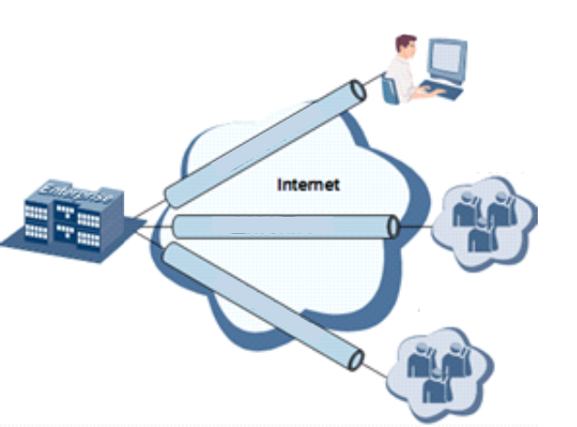
Build a credible and secure link by connecting remote users, company branches, partners to the
network of the headquarters via VPN so as to realize secure transmission of data.
It is shown in the figure below:
Enterprise
Headquarter Embranchment
Cooperative
Partner
VPN
VPN
VPN
Remote Access
Fundamental Principle of VPN
The fundamental principle of VPN indicates to enclose VPN message into tunnel with tunneling
technology and to establish a private data transmission channel utilizing VPN Backbone so as to
realize the transparent message transmission.
Tunneling technology encloses the other protocol message with one protocol. Also,
encapsulation protocol itself can be enclosed or carried by other encapsulation protocols. To the
users, tunnel is logical extension of PSTN/link of ISDN, which is similar to the operation of actual
physical link.
VPN settings include IPSec settings, IPSec tunnels, GRE tunnels, L2TP client, PPTP client,
OpenVPN, OpenVPN Advanced and certificate management.
3.6.1 IPSec Settings
A majority of data contents are Plaintext Transmission on the Internet, which has many potential

36
dangers such as password and bank account information stolen and tampered, user identity
imitated, suffering from malicious network attack, etc. After disposal of IPSec on the network,
it can protect data transmission and reduce risk of information disclosure.
IPSec is a group of open network security protocol made by IETF, which can ensure the security of
data transmission between two parties on the Internet via data origin authentication, data
encryption, data integrity and anti-replay function on the IP level. It is able to reduce the risk of
disclosure and guarantee data integrity and confidentiality and well as maintain security of
service transmission of users.
IPSec, including AH, ESP and IKE, can protect one and more date flows between hosts, between
host and gateway, and between gateways. The security protocols of AH and ESP can ensure
security and IKE is used for cipher code exchange.
IPSec can establish bidirectional Security Alliance on the IPSec peer pairs to form a secure and
interworking IPSec tunnel and to realize the secure transmission of data on the Internet.
From navigation tree, select VPN>>IPSec Settings, then enter “IPSec Settings” page.
Table 3-6-1 Parameters of IPSec Settings
IPSec settings
Function description: 1. Select whether to enable NATT, generally this is enabled, unless it is
confirmed that there is no NAT router in the network. In order to keep VPN
tunnel connected, NATT interval should be properly set.
2. Select whether to enable compression and debug mode.
Parameters
Description
Default
Enable NAT-Traversal (NATT)
Click to enable NAT-Traversal
Enable
Keep alive time interval of
NAT
Set alive time interval of NAT
60 s
Enable Compression
Click to enable compression
Enable
Force NATT
Click to enable force NATT
Disable
Dynamic NATT Port
Click to enable dynamic NATT port
Disable
3.6.2 IPSec Tunnels
From navigation tree, select VPN>>IPSec Tunnels, enter "IPSec Tunnels" and click <add>.
Table 3-6-2 Parameters of IPSec Tunnels
IPSec Tunnels
Function description: Configure IPSec tunnels

37
Parameters
Description
Default
Show Advanced Options
Click to enable advanced
options
Disable (open advanced
options after enabling)
Basic parameters
Tunnel Name
User defines tunnel name
IPSec_tunnel_1
Destination Address
Set destination IP address or
domain name
0. 0. 0. 0
Startup Modes
Select Auto
Activated/Triggered by
Data/Passive/Manually
Activated
Auto Activated
Restart WAN when failed
Click to enable
Enable
Negotiation Mode
Select main mode or
aggressive mode
Main Mode
IPSec Protocol (Advanced
Option)
Select ESP/AH
ESP
IPSec Mode (Advanced
Option)
Select tunnel
mode/transmission mode
Tunnel Mode
VPN over IPSec (Advanced
Option)
Select L2TP over IPSec/GRE
over IPSec/None
None
Tunnel Type
Select
Host-Host/Host-Subnet/Subne
t-Host/Subnet-Subnet
Subnet-Subnet
Local subnet address
Set local subnet IP address
192. 168. 2. 1
Local Subnet Mask
Set local subnet mask
255. 255. 255. 0
Peer Subnet Address
Set peer subnet IP address
0. 0. 0. 0
Peer Subnet Mask
Set remote netmask
255. 255. 255. 0
Phase I Parameters
IKE Strategy
Multiple strategies available
3DES-MD5-DH2
IKE Life Cycle
Set IKE life cycle
86400 s
Local ID Type
Select IP address/User
FQDN/FQDN Fill in the ID
according to the ID type
(USERFQDN is standard email
format)
IP Address
Peer ID Type
Select IP address/User
FQDN/FQDN
IP Address
Authentication method
Select shared key/digital
certificate
Shared key
Key
Set IPSec VPN key
N/A
XAUTH Parameters (Advanced Option)
XAUTH Mode
Click to enable XAUTH mode
Disable
XATUTH username
User defines XATUTH
N/A

38
username
XATUTH password
User defines XATUTH
password
N/A
MODECFG
Click to enable MODECFG
Disable
Phase II Parameters
IPSec Strategy
Multiple strategies available
3DES-MD5-96
IPSec Life Cycle
Set IPSec life cycle
3600 s
Perfect Forward Secrecy
(PFS) (Advanced Option)
Select disable/Group 1/Group
2/Group 5
Disable (this needs to match
the server)
Link Detection Parameters (Advanced Option)
DPD Interval
Set time interval.
60 s
DPD Timeout
Set the timeout for dropped
packets.
180 s
ICMP Detection Server
Set ICMP detection server
N/A
ICMP Detection Local IP
Set ICMP detection local IP
N/A
ICMP Detection Interval
Set ICMP Detection Interval
60 s
ICMP Detection Timeout
Set ICMP detection timeout
5 s
ICMP Detection Retries
Set ICMP detection max.
retries
10
The security level of three encryption algorithms ranks successively: AES, 3DES, DES. The
implementation mechanism of encryption algorithm with stricter security is complex and slow
arithmetic speed. DES algorithm can satisfy the ordinary safety requirements.
3.6.3 GRE Tunnels
Generic Route Encapsulation (GRE) defines the encapsulation of any other network layer protocol
on a network layer protocol. GRE could be used as the L3TP of VPN to provide a transparent
transmission channel for VPN data. In simple terms, GRE is a tunneling technology which provides
a channel through which encapsulated data message could be transmitted and encapsulation and
decapsulation could be realized at both ends. GRE tunnel application networking shown as the
following figure:
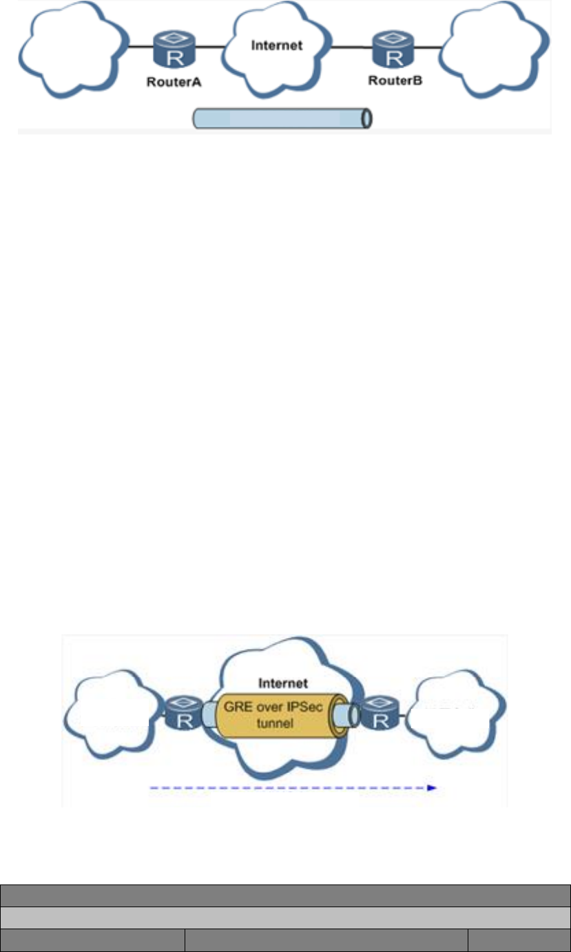
39
X Network X Network
GRE Tunnel
Along with the extensive application of IPv4, to have messages from some network layer protocol
transmitted on IPv4 network, those messages could by encapsulated by GRE to solve the
transmission problems between different networks.
In following circumstances GRE tunnel transmission is applied:
GRE tunnel could transmit multicast data packets as if it were a true network interface.
Single use of IPSec cannot achieve the encryption of multicast.
A certain protocol adopted cannot be routed.
A network of different IP address shall be required to connect other two similar networks.
GRE application example: combined with IPSec to protect multicast data
GRE can encapsulate and transmit multicast data in GRE tunnel, but IPSec, currently, could only
carry out encryption protection against unicast data. In case of multicast data requiring to be
transmitted in IPSec tunnel, a GRE tunnel could be established first for GRE encapsulation of
multicast data and then IPSec encryption of encapsulated message so as to achieve the
encryption transmission of multicast data in IPSec tunnel. As shown below:
Enterprise
Intranet Telecommuting
IP Multicast Streams
From navigation tree, select VPN>>GRE Tunnels and enter "GRE Tunnels".
Table 3-6-3 Parameters of GRE Tunnels
2 GRE Tunnels
Function description: Configure GRE tunnels
Parameters
Description
Default

40
Enable
Click to enable GRE
Enable
Name
User defines name of GRE tunnel
tun0
Local visual IP
Set local virtual IP
0. 0. 0. 0
Destination Address
Set remote IP address
0. 0. 0. 0
Peer visual IP
Set peer virtual IP
0. 0. 0. 0
Peer Subnet Address
Set peer subnet IP address
0. 0. 0. 0
Peer Subnet Mask
Set remote netmask
255. 255.
255. 0
Key
Configure the key of GRE tunnel
N/A
NAT
Click to enable NAT
Disable
Description
For recording the significance of each GRE
tunnel configuration
N/A
3.6.4 L2TP Client
L2TP, one of VPDN TPs, has expanded the applications of PPP, known as a very important VPN
technology for remote dial-in user to access the network of enterprise headquarters.
L2TP, through dial-up network (PSTN/ISDN), based on negotiation of PPP, and could establish a
tunnel between enterprise branches and enterprise headquarters so that remote user has access
to the network of enterprise headquarters. PPPoE is applicable in L2TP. Through the connection
of Ethernet and Internet, a L2TP tunnel between remote mobile officers and enterprise
headquarters could be established.
L2TP-Layer 2 Tunnel Protocol encapsulates private data from user network at the head of L2 PPP.
No encryption mechanism is available, thus IPSes is required to ensure safety.
Main Purpose: branches in other places and employees on a business trip could access to the
network of enterprise headquarter through a virtual tunnel by public network remotely.
Typical L2TP network diagram is shown below:

41
RADIUS Server RADIUS Server
Enterprise
Branch
Dialling User
Enterprise
Headquarter
Mobile Office Staff
(L2TP Dialling Software)
L2TP Tunnel
L2TP Tunnel
From navigation tree, select VPN>>L2TP Client, enter "L2TP Client" and click <add>.
Table 3-6-4 Parameters of L2TP Client
3 L2TP Client
Function description: Configure parameters of L2TP client.
Parameters
Description
Default
Enable
Click to enable L2TP client
Disable
Tunnel Name
User defines tunnel name of L2TP client
L2TP_tunnel_1
L2TP Server
Set L2TP Server address
N/A
Username
Set server's username
N/A
Password
Set server's password
N/A
Server Name
Set server name
l2tpserver
Startup Modes
Select Auto Activated/Triggered by
Data/Passive/Manually
Activated/L2TPOverIPSec
Auto Activated
Authentication Method
Select CHAP/PAP
CHAP
Enable Challenge secrets
Click to enable challenge secrets
Disable
Challenge secret (after
enabling)
Set challenge secret
N/A
Local IP Address
Set local IP address
N/A
Remote IP Address
Set remote IP address
N/A
Remote Subnet
Set remote subnet address
N/A
Remote Netmask
Set remote subnet mask
255. 255.
255. 0
Link Detection Interval
Set link detection interval
60 s
Max. Retries for Link
Detection
Set the max. number of retries
5
Enable NAT
Click to enable NAT
Disable
MTU
Set max. transmission unit
1500
MRU
Set max. receiving unit
1500
Enable Debug
Enable debug mode.
Disable

42
Expert Option (not
recommended)
Set expert option, not recommended
N/A
3.6.5 PPTP Client
From navigation tree, select VPN>>PPTP Client, enter "PPTP Client" and click <add>.
Table 3-6-5 Parameters of PPTP Client
4 PPTP Client
Function description: Configure parameters of PPTP client.
Parameters
Description
Default
Enable
Click to enable PPTP client
Disable
Tunnel Name
User defines tunnel name
PPTP_tunnel_1
PPTP Server
Set PPTP Server address
N/A
Username
Set username of PPTP server
N/A
Password
Set password of PPTP server
N/A
Startup Modes
Select Auto Activated/Triggered by
Data/Passive/Manually Activated
Auto Activated
Authentication method
Select
Auto/CHAP/PAP/MS-CHAPv1/MS-CHAPv2
Auto
Local IP Address
Set local IP address
N/A
Remote IP Address
Set remote IP address
N/A
Remote Subnet
Set remote subnet address
N/A
Remote Netmask
Set remote subnet mask
255. 255.
255. 0
Link Detection Interval
Set link detection interval
60 s
Max. Retries for Link
Detection
Set the max. number of retries
5
Enable NAT
Click to enable NAT
Disable
Enable MPPE
Click to enable MPPE
Disable
Enable MPPC
Click to enable MPPC
Disable
MTU
Set max. transmission unit
1500
MRU
Set max. receiving unit
1500
Enable Debug
Enable debug mode.
Disable
Set expert option (not
recommended)
Set expert option, not recommended
N/A
3.6.6 OpenVPN
Single point participating in the establishment of VPN is allowed to carry out ID verification by
preset private key, third-party certificate or username/password. OpenSSL encryption library and

43
SSLv3/TLSv1 protocol are massively used.
In OpenVPN, if a user needs to access to a remote virtual address (address family matching
virtual network card), then OS will send the data packet (TUN mode) or data frame (TAP mode) to
the visual network card through routing mechanism. Upon the reception, service program will
receive and process those data and send them out through outer net by SOCKET, owing to which,
the remote service program will receive those data and carry out processing, then send them to
the virtual network card, then application software receive and accomplish a complete
unidirectional transmission, vice versa.
From navigation tree, select "VPN>>OpenVPN", then enter “OpenVPN” page, and click <Add>.
Table 3-6-6 IPSec Configuration Parameters
OpenVPN
Function description: Configure OpenVPN parameters.
Parameters
Description
Default
Tunnel Name
OpenVPN tunnel name, cannot be changed
by the system
OpenVPN_T_1
Enable
Click to enable
Enable
Mode
Client/server
Client
Protocol
UDP/ICMP
UDP
Port
Set port
1194
OPENVPN Server
Set OPENVPN Server address
N/A
Authentication method
N/A, pre-shared key, username/password,
digital certificate (multiple client), digital
certificate, username+digital certificate
N/A
Local IP Address
Set local IP address
N/A
Remote IP Address
Set remote IP address
N/A
Remote Subnet
Set remote subnet address
N/A
Remote Netmask
Set remote subnet mask
255. 255.
255. 0
Link Detection Interval
Set link detection interval
60 s
Link Detection Timeout
Set link detection timeout
300 s
Enable NAT
Click to enable NAT
Enable
Enable LZO
Click to enable LZO compression
Enable
Encryption Algorithms
Blowfish(128)/DES(128)/3DES(192)/AES(128)
/AES(192)/AES(256)
Blowfish(128)
MTU
Set max. transmission unit
1500
Max. Fragment Size
Set max. fragment size
N/A
Debug Level
Error/warning/information/debug
Warning
Interface Type
TUN/TAP
TUN

44
Expert Option (not
recommended)
Set expert option, not recommended
N/A
3.6.7 OpenVPN Advanced
From navigation tree, select "VPN>>OpenVPN Advanced" and enter "OpenVPN Advanced"
interface.
Table 3-6-7 Configuration Parameters of OpenVPN Advanced
OpenVPN Advanced
Function description: Configure parameters of OpenVPN Advanced.
Parameters
Description
Default
Enable Client-to-Client
(Server Mode Only)
Click to enable
Disable
Client Management
Enable
Click to enable client management
Enable
Tunnel Name
Set tunnel name
OpenVPN_T_1
Username/CommonName
Set username/commonname
N/A
Password
Set client password
N/A
Client IP (4th byte must be
4n+1)
Set client IP address
N/A
Local Static Route
Set local static route
N/A
Remote Static Route
Set remote static route
N/A
3.6.8 Certificate Management
From navigation tree, select VPN>> Certificate Management, then enter “Certificate
Management” page.
Table 3-6-8 Parameters of Certificate Management
Certificate Management
Function description: Configure parameters of certificate management.
Parameters
Description
Default
Enable SCEP (Simple
Certificate Enrollment
Protocol)
Click to enable
Disable
Protect Key
Set protect key
N/A
Protect Key Confirm
Confirm protect key
N/A
Enable SCEP (Simple Certificate Enrollment Protocol)
Force to Re-enroll
Click to enable force to re-enroll
Disable
Request Status
The system is "ready to refile an enrollment",
Ready to refile

45
cannot be changed
an enrollment
Server URL
Set server URL
N/A
Common Name
Set common name
N/A
FQDN
Set FQDN
N/A
Unit 1
Set unit 1
N/A
Unit 2
Set unit 2
N/A
Domain
Set domain
N/A
Serial Number
Set serial number
N/A
Challenge
Set challenge
N/A
Challenge Confirm
Challenge confirm
N/A
Protect Key
Set protect key
N/A
Protect Key Confirm
Confirm protect key
N/A
Unstructured address
Set unstructured address
N/A
RSA Key Length
Set RSA key length
1024
Poll Interval
Set poll interval
60 s
Poll Timeout
Set poll timeout
3600 s
3.7 Tools
The tools include PING detection, traceroute and link speed test.
3.7.1PING Detection
To do a ping, enter the navigation tree, select Tools>>Ping Detection, then enter the “Ping
Detection” page.
Table 3-7-1 PING Detection Parameters
1 PING Detection
Function description: PING outside network.
Parameters
Description
Default
Host
Address of the destination host of PING
detection is required.
N/A
PING Count
Set the PING count
4
Packet Size
Set the size of PING detection
32 bytes
Expert Option
Advanced parameter of PING is
available.
N/A
3.7.2Traceroute
To preform traceroute, select "Tools>>Traceroute" menu in the navigation tree, then enter the

46
“Traceroute” page.
Table 3-7-2 Traceroute Parameters
Traceroute
Function description: Applied for network routing failures detection.
Parameters
Description
Default
Host
Address of the destination host which to
be detected is required.
N/A
Max. Hops
Set the max. hops for traceroute
20
Timeout
Set the timeout of traceroute
3 s
Protocol
ICMP/UDP
UDP
Expert Option
Advanced parameter for traceroute is
available.
N/A
3.7.3 Link Speed Test
Enter the navigation tree, select Tools>>Link Speed Test, then enter the “Link Speed Test” page.
3.8 Status
The status includes system, modem, network connections, routing table, device List and log.
3.8.1 System
From navigation tree, select Status >> System, then enter the “System” page.
This page displays system statistics, including name, model, serial number, description, current
version, current Bootloader version, router time, PC time, UP time, CPU load and memory
consumption. Technicians may click the <Sync Time> button to synchronize the router with the
system time of the host, as covered in the set-up chapter.
3.8.2 Modem
From navigation tree, select Status >> Modem, then enter the “Modem” page.
This page displays the basic information of dialup, including status, signal level, register status,
IMEI (ESN) code, IMSI code, LAC and cell ID.
47
3.8.3 Network Connections
From navigation tree, select Status >> Network Connections, then enter “Network Connections”
page to see the connections status.
This page shows the basis information of dialup and LAN.
Dialup includes connection type, IP address, netmask, gateway, DNS, MTU, status and connection
time.
LAN includes MAC address, IP address, netmask, gateway, MTU and DNS.
3.8.4 Route Table
From navigation tree, select Status >> Route Table, then enter “Route Table” page to see router
status.
This page displays the active route table, including destination, netmask, gateway, metric and
interface.
3.8.5 Device List
From navigation tree, select Status >> Device List, then enter “Device List” page to inquire the
device list.
This page displays the device list, including interface, MAC address, IP address, host and lease
(click MAC address to link to IEEE to inquire validity of the address).
3.8.6 Log
From navigation tree, select Status >> Log, then enter “Log” page.
This page displays the logs, including select to see the number of log lines (20/50/....../all), log
level (information, debug and warning), time, module and content. Clear log, download log file,
download system diagnosis record (refresh rate of this page is 5/10/…... 1min by default)
48
Appendix A FAQ
1. InRouter is powered on, but can't access Internet through it?
Please first check:
Whether the InRouter is inserted with a SIM card.
Whether the SIM card is enabled with data service, whether the service of the SIM card
is suspended because of an overdue charge.
Whether the dialup parameters, e.g. APN, dialup number, username and password
are correctly configured.
Whether the IP Address of your computer is the same subnet with InRouter and the
gateway address is InRouter LAN address. ;
2. InRouter is powered on, have a ping to detect InRouter from your PC and find packet loss?
Please check if the network crossover cable is in good condition.
3. Forget the setting after revising IP address and can't configure InRouter?
Method 1: connect InRouter with serial cable, configure it through console port.
Method 2: Within 5 seconds after InRouter is powered on, press and hold the Restore
button until the ERROR LED flashes, then release the button and the ERROR LED
should goes off, press and hold the button again until the ERROR LED blinks 6
times, the InRouter is now restored to factory default settings.
You may configure it now.
4. After InRouter is powered on, it frequently auto restarts. Why does this happen?
First check:
Whether the module works normally.
Whether the InRouter is inserted with a SIM card.
Whether the SIM card is enabled with data service, whether the service of the SIM
card is suspended because of an overdue charge.
Whether the dialup parameters, e.g. APN, dialup number, username and
password are correctly configured.
Whether the signal is normal.
Whether the power supply voltage is normal.
5. Why does upgrading the firmware of my InRouter always fail?
Examination:
When upgrading locally, check if the local PC and InRouter are in the same network
segment.
When upgrading remotely, please first make sure the InRouter can access Internet.
6. After InRouter establishes VPN with the VPN server, your PC under InRouter can connect to the
49
server, but the center can't connect to your PC under InRouter?
Please make sure the firewall of your computer is disabled.
7. After InRouter establishes VPN with the VPN server, your PC under InRouter can't connect to
the server ping?
Please make sure “Shared Connection” on “Network=>WAN” or “Network=>Dialup” is enabled in
the configuration of InRouter.
8. InRouter is powered on, but the Power LED is not on?
Check if the protective tube is burn out.
Check the power supply voltage range and if the positive and negative electrodes are
correctly connected.
9. InRouter is powered on, but the Network LED is not on when connected to PC?
When the PC and InRouter are connected with a network cable, please check whether
a network crossover cable is used.
Check if the network cable is in good condition.
Please set the network card of the PC to 10/100M and full duplex.
10. InRouter is powered on, when connected with PC, the Network LED is normal but can't have a
ping detection to the InRouter?
Check if the IP Address of the PC and InRouter are in the same subnet and the gateway
address is InRouter LAN address.
11. InRouter is powered on, but can't configure through the web interface?
Whether the IP Address of your computer is the same subnet with InRouter and the
gateway address is InRouter LAN address.
Check the firewall settings of the PC used to configure InRouter, whether this function
is shielded by the firewall.
Please check whether your IE has any third-party plugin (e.g. 3721 and IEMate). It is
recommended to configure after unloading the plugin.
12. The InRouter dialup always fails, I can't find out why?
Please restore InRouter to factory default settings and configure the parameters again.
13. How to restore InRouter to factory default settings?
The method to restore InRouter to factory default settings:
1. Press and hold the Restore button, power on InRouter;
2. Release the button until after the STATUS LED flashes and the ERROR LED is on;
3. After the button is released, the ERROR LED will go off, within 30s press and hold the
Restore button again until the ERROR LED flashes;
4. Release the button, the system is now successfully restored to factory default
50
settings.
Appendix B Instruction of Command Line
1Help Command
Help command can be obtained after entering help or “?” into console, “?” can be entered
at any time during the process of command input to obtain the current command or help from
command parameters, and command or parameters can be automatically complemented in case
of only command or command parameter.
1.1 Help
[Command] Help [<cmd>]
[Function] Get help from command.
[View] All views
[Parameter]
<cmd> command name
[Example]
Enter:
help
Get the list of all current available command.
enter:
help show
Display all the parameters of show command and using instructions thereof.
2View Switchover Command
2.1Enable
[Command] Enable [15 [<password>]]
[Function] Switchover to privileged user level.
[View] Ordinary user view.
[Parameter]15 User right limit level, only supports right limit 15 (super users) at
current.
<password> Password corresponded to privileged user limit level, hint of password
51
inputting will be given in case of no entering.
[Example]
Enter exit in ordinary user view:
enable 123456
Switchover to super users and the password 123456.
2.2 Disable
[Command] Disable
[Function] Exit the privileged user level.
[View] Super user view, configure view
[Parameter] No
[Example]
Enter in super user view:
disable
Return to ordinary user view.
2. 3 End and !
[Command] End or !
[Function] Exit the current view and return to the last view.
[View] Configure view.
[Parameter] No
[Example]
Enter in configured view:
end
Return to super user view.
2. 4 Exit
[Command] Exit
[Function] Exit the current view and return to the last view (exit console in case that it is ordinary
user)
[View] All views
[Parameter] No
[Example]
52
Enter in configured view:
exit
Return to super user view.
enter exit in ordinary user view:
exit
Exit console.
3 Check system state command
3. 1 Show version
[Command] Show version
[Function] Display the type and version of software of router
[View] All views
[Parameter] No
[Example]
Enter:
show version
Display the following information:
Type : display the current factory type of equipment
Serial number : display the current factory serial number of equipment
Description : www.inhand.com.cn
Current version : display the current version of equipment
Current version of Bootloader: display the current version of equipment
3. 2 Show system
[Command] Show system
[Function] Display the information of router system
[View] All views
[Parameter] No
[Example]
Enter:
show system
Display the following information:
53
Example: 00:00:38 up 0 min, load average: 0.00, 0.00, 0.00
3. 3 show clock
[Command] Show clock
[Function] Display the system time of router
[View] All views
[Parameter] No
[Example]
Enter:
show clock
Display the following information:
For example Sat Jan 1 00:01:28 UTC 2000
3. 4 Show modem
[Command] Show modem
[Function] Display the MODEM state of router
[View] All views
[Parameter] No
[Example]
Enter:
show modem
Display the following information:
Modem type
state
manufacturer
Product name
signal level
register state
IMSI number
Network Type
3. 5 Show log
[Command] Show log [lines <n>]
54
[Function] Display the log of router system and display the latest 100 logs in default.
[View] All views
[Parameter]
Lines <n> limits the log numbers displayed, wherein, n indicates the latest n logs in
case that it is positive integer and indicates the earliest n logs in case that it is negative
integer and indicates all the logs in case that it is 0.
[Example]
Enter:
show log
Display the latest 100 log records.
3. 6 Show users
[Command] Show users
[Function] Display the user list of router.
[View] All views
[Parameter] No
[Example]
Enter:
show users
Displayed user list of system is as follows:
User:
-------------------------------------------------
* adm
------
Wherein, user marked with * is super user.
3. 7 Show startup-config
[Command] Show startup-config
[Function] Display the starting device of router.
[View] Super user view and configuration view
[Parameter] No
[Example]
55
Enter:
show startup-config
Display the starting configuration of system.
3. 8 Show running-config
[Command] Show running-config
[Function] Display the operational configuration of router
[View] Super user view and configuration view
[Parameter] No
[Example]
Enter:
show startup-config
Display the operational configuration of system.
4 Check Network Status Command
4. 1 Show interface
[Command] Show interface
[Function] Display the information of port state of router
[View] All views
[Parameter] No
[Example]
Enter:
show interface
Display the state of all ports.
4. 2 Show ip
[Command] Show ip
[Function] Display the information of port state of router
[View] All views
[Parameter] No
[Example]
Enter:
Show ip
56
Display system ip status
4. 3 Show route
[Command] Show route
[Function] Display the routing list of router
[View] All views
[Parameter] No
[Example]
enter:
show route
Display the routing list of system
4. 4 Show arp
[Command] Show arp
[Function] Display the ARP list of router
[View] All views
[Parameter] No
[Example]
Enter:
show arp
Display the ARP list of system
5 Internet Testing Command
Router has provided ping , telnet and traceroute for Internet testing.
5. 1 Ping
[Command] Ping <hostname> [count <n>] [size <n>] [source <ip>]
[Function] Apply ICMP testing for appointed mainframe.
[View] All views
[Parameter]
<hostname> tests the address or domain name of mainframe.
count <n> testing times
size <n> tests the size of data package (byte)
source <ip> IP address of appointed testing
57
[Example]
Enter:
ping www.g.cn
Test www. g. cn and display the testing results
5. 2 Telnet
[Command] Telnet <hostname> [<port>] [source <ip>]
[Function] Telnet logs in the appointed mainframe
[View] All views
[Parameter]
<hostname> in need of the address or domain name of mainframe logged in.
<port>telnet port
source <ip> appoints the IP address of telnet logged in.
[Example]
Enter:
telnet 192.168.2.2
telnet logs in 192. 168. 2. 2
5. 3 Traceroute
[Command] Traceroute <hostname> [maxhops <n>] [timeout <n>]
[Function] Test the acting routing of appointed mainframe.
[View] All views
[Parameter]
<hostname> tests the address or domain name of mainframe.
maxhops <n> tests the maximum routing jumps
timeout <n> timeout of each jumping testing (sec)
[Example]
Enter:
traceroute www.g.cn
Apply the routing of www. g. cn and display the testing results.
6 Configuration Command
In super user view, router can use configure command to switch it over configure view for
58
management.
Some setting command can support no and default, wherein, no indicates the setting of
canceling some parameter and default indicates the recovery of default setting of some
parameter.
6. 1 Configure
[Command] Configure terminal
[Function] Switchover to configuration view and input the equipment at the terminal end.
[View] Super user view
[Parameter] No
[Example]
Enter in super user view:
configure terminal
Switchover to configuration view.
6. 2 Hostname
[Command] Hostname [<hostname>]
default hostname
[Function] Display or set the mainframe name of router.
[View] Configure view.
[Parameter]
<hostname> new mainframe name
[Example]
Enter in configured view:
hostname
Display the mainframe name of router.
Enter in configured view:
hostname MyRouter
Set the mainframe name of router MyRouter.
Enter in configured view:
defaulthostname
Recover the mainframe name of router to the factory setting.
6. 3 Clock timezone
59
[Command] Clock timezone <timezone><n>
default clock timezone
[Function] Set the time zone information of the router.
[View] Configure view.
[Parameter]
<timezone> timezone name, 3 capitalized English letters
<n> time zone deviation value, -12~+12
[Example]
Enter in configured view:
clock timezone CST -8
The time zone of IG601is east eighth area and the name is CST (China's standard time).
Enter in configured view:
default clock timezone
Recover the timezone of router to the factory setting.
6. 4 Clock set
[Command] Clock set <YEAR/MONTH/DAY> [<HH:MM:SS>]
[Function] Set the date and time of router.
[View] Configure view.
[Parameter]
<YEAR/MONTH/DAY> date, format: Y-M-D
<HH:MM:SS > time, format: H-M-S
[Example]
Enter in configured view:
clock set 2009-10-5 10:01:02
The time of router set is 10:01:02 of Oct. 5th, 2009 morning.
6. 5 Ntp server
[Command]
ntp server <hostname>
no ntp server
default ntp server
60
[Function] Set the customer end of Internet time server
[View] Configure view.
[Parameter]
<hostname> address or domain name of mainframe of time server
[Example]
Enter in configured view:
ntp server pool.ntp.org
Set the address of Internet time server pool. ntp. org.
Enter in configured view:
no ntp server
Disable the router to get system time via network.
Enter in configured view:
default ntp server
Recover the network time server of router to the factory setting.
6. 6 Config export
[Command] Config export
[Function] Export config
[View] Configure view.
[Parameter] No
[Example]
Enter in configured view:
config export
The current config. is exported.
6. 7 Config import
[Command] Config import
[Function] Import config
[View] Configure view.
[Parameter] No
[Example]
Enter in configured view:
config import
61
The config. is imported.
7 System Management Command
7. 1 Reboot
[Command] Reboot
[Function] System restarts.
[View] Super user view and configuration view
[Parameter] No
[Example]
Enter in super user view:
reboot
System restarts.
7. 2 Enable username
[Command] Enable password [<name>]
[Function] Modify the username of super user.
[View] Configure view.
[Parameter]
<name> new super user username
[Example]
Enter in configured view:
enable username admin
The username of super user is changed to admin.
7. 3 Enable password
[Command] Enable password [<password>]
[Function] Modify the password of super user.
[View] Configure view.
[Parameter]
<password> new super user password
[Example]
Enter in configured view:
enable password
62
Enter password according to the hint.
7. 4 Username
[Command] Username <name> [password [<password>]]
no username <name>
default username
[Function] Set user name, password
[View] Configure view.
[Parameter] No
[Example]
Enter in configured view:
username abc password 123
Add an ordinary user, the name is abc and the password is 123.
Enter in configured view:
no username abc
Delete the ordinary user with the name of abc.
Enter in configured view:
default username
Delete all the ordinary users.

FCCwarning:
Any Changes or modifications not expressly approved by the party responsible for
compliance could void the user's authority to operate the equipment.
This device complies with part 15 of the FCC Rules. Operation is subject to the following
two conditions: (1) This device may not cause harmful interference, and (2) this device
must accept any interference received, including interference that may cause undesired
operation.
Note:This equipment has been tested and found to comply with the limits for a Class A digital
device, pursuant to part 15 of the FCC Rules. These limits are designed to provide reasonable
protection against harmful interference when the equipment is operated in a commercial
environment. This equipment generates, uses, and can radiate radio frequency energy and, if
not installed and used in accordance with the instruction manual, may cause harmful
interference to radio communications. Operation of this equipment in a residential area is likely
to cause harmful interference in which case the user will be required to correct the interference
at his own expense.
FCC Radiation Exposure Statement
This equipment complies with FCC radiation exposure limits set forth for an
uncontrolled environment .This equipment should be installed and operated with
minimum distance 40cm between the radiator& your body.
This transmitter must not be co-located or operating in conjunction with any other antenna or
transmitter.