Belco Co XG2500 CORDLESS TELEPHONE EQUIPMENT User Manual
Belco International Co Ltd CORDLESS TELEPHONE EQUIPMENT
UserManual.wiki
>
Belco Co
>
XG2500 User Manual
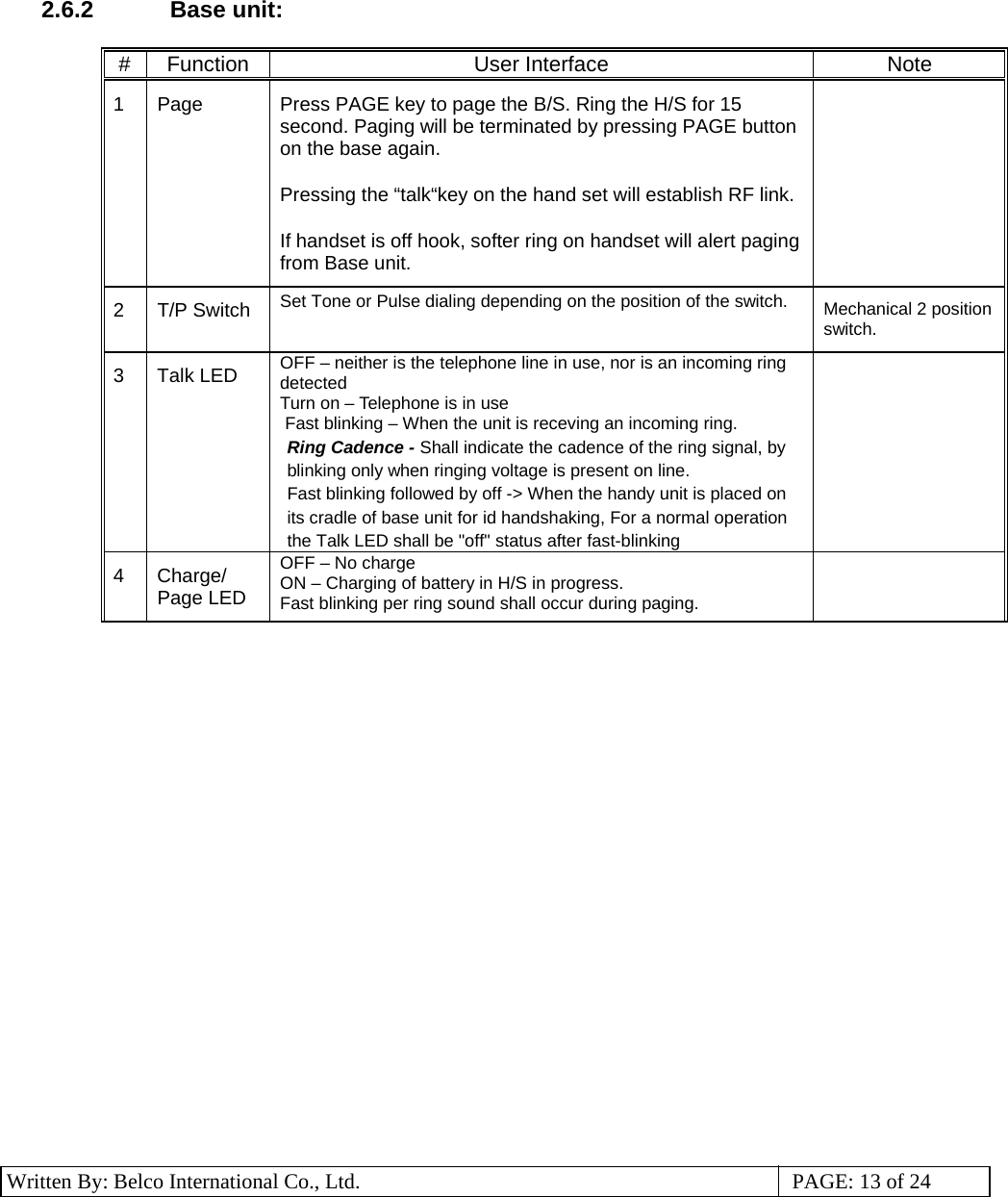
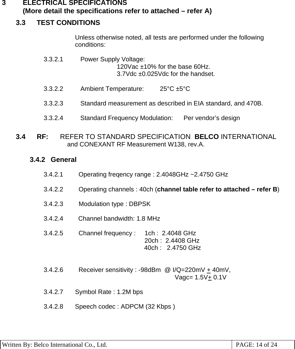
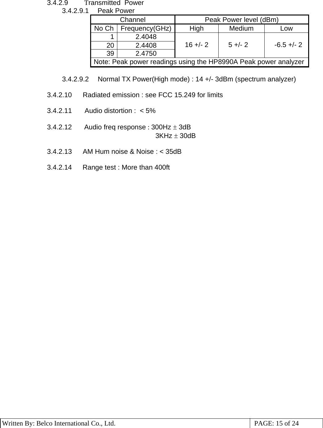
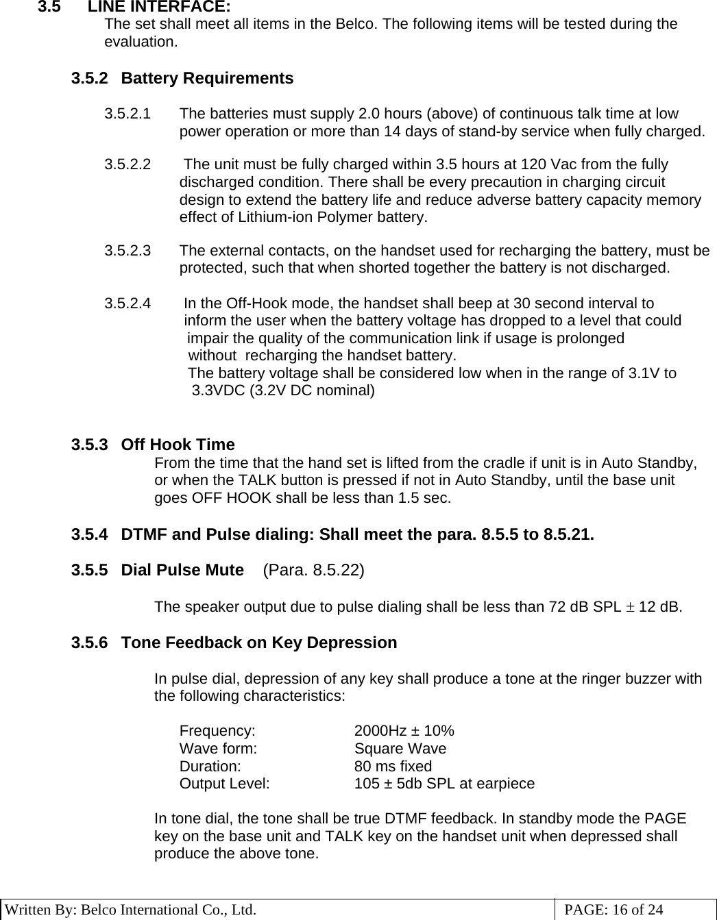
USERS MANUAL
Navigation menu
Upload a User Manual
Namespaces
Wiki Guide
HTML
PDF
Info
Views
User Manual
Discussion / Help
Navigation