Belco Co XG2500 CORDLESS TELEPHONE EQUIPMENT User Manual
Belco International Co Ltd CORDLESS TELEPHONE EQUIPMENT
Belco Co >
USERS MANUAL
3
Complied By: Jerry Lee Approved by: First Issued: 16Aug/2004
Div. or Dept.: R & D Dept. Issue: First
Location: Copy To:
Page: 1 of 20

3
Written By: Belco International Co., Ltd. PAGE: 2 of 24
TABLE OF CONTENTS
1. FUNCTIONAL SUMMARY _________________________________________________3
1.1. Scope -----------------------------------------------------------------------------------------------------------------------------3
1.2. Features--------------------------------------------------------------------------------------------------------------------------3
1.3. Unit as Received---------------------------------------------------------------------------------------------------------------3
1.4. Appearance ---------------------------------------------------------------------------------------------------------------------4
1.5. Date Coding---------------------------------------------------------------------------------------------------------------------4
1.6. Labeling -------------------------------------------------------------------------------------------------------------------------4
1.7. Standards & References----------------------------------------------------------------------------------------------------5
1.8. Regulatory Approvals Required------------------------------------------------------------------------------------------5
1.9. Safety -----------------------------------------------------------------------------------------------------------------------------5
1.10. Factory or After Sales Service Interface-------------------------------------------------------------------------------6
1.11. Compatibility -------------------------------------------------------------------------------------------------------------------7
1.12 Security Code Information-------------------------------------------------------------------------------------------------7
2. USER INTERFACE DESCRIPTION __________________________________________8
2.1. Initial Factory Settings ------------------------------------------------------------------------------------------------------8
2.2. Default Settings----------------------------------------------------------------------------------------------------------------8
2.3. Ringing and Tones -----------------------------------------------------------------------------------------------------------8
2.4. Display ------------------------------------------------------------------------------------------------------------------------- 10
2.7. Operating Procedures ---------------------------------------------------------------------------------------------------- 11
3. ELECTRICAL SPECIFICATIONS___________________________________________14
3.1. Test Conditions-------------------------------------------------------------------------------------------------------------- 14
3.2. RF -------------------------------------------------------------------------------------------------------------------------------- 14
3.3. Line Interface ---------------------------------------------------------------------------------------------------------------- 16
4. ENVIRONMENTAL ______________________________________________________18
4.1. Purpose of Specification ------------------------------------------------------------------------------------------------- 18
4.2. Temperature Performance ----------------------------------------------------------------------------------------------- 18
4.3. Electrostatic Discharge --------------------------------------------------------------------------------------------------- 18
4.4. Humidity------------------------------------------------------------------------------------------------------------------------ 18

3
Written By: Belco International Co., Ltd. PAGE: 3 of 24
1. FUNCTIONAL SUMMARY
1.1. SCOPE
This specification defines the product features and requirements of the 2.4GHz
Digtal Spread Spectrum Technology (DSST) features.
40 channels 2.4 GHz Basic Cordless telephone.
1.2. FEATURES:
⇒ 2.4 GHz Digital Spread Spectrum Technology (DSST)
⇒ Mechanical T/P select switch
⇒ Page button on the Basease unit
⇒ Built in Buzzer on Base unit
⇒ Earloop on handset
⇒ Any Key Talk
⇒ Built in Battery on Handset
⇒ Auto ON-HOOK:
The unit shall automatically be placed on-hook when the handset is placed in the
charging cradle, or when the handset has been determined to be Out-of-Range
for a sufficient period of time.
⇒ # of Channels: 40
⇒ # of Memories: N.A
⇒ # of digits in the memory: N.A
⇒ # of digits in Redial buffer: 32 Digit
1.3. UNIT AS RECEIVED -
The package as received shall consist of the following:
1.3.1. Telephone Base unit Model XG-2500 DSST
Pulse/Tone switch setting to the Tone mode
1.3.2. Telephone Handset model XG-2500 DSST
Volume set to Nominal Position
Consumer-replaceable Earloop installed
1.3.3. Accessory:
Item Description/Model #
AC/DC Converter External
Telephone Line Cord
Length 6 feet, straight; terminated in
USOC RJ11C modular plug.
Ear loop (Clip) Accessory Item (included)
3
Written By: Belco International Co., Ltd. PAGE: 4 of 24
1.3.4. Printed Materials:
1.3.5. Packaging:
1.4. APPEARANCE
1.5. DATE CODING
1.5.1. Location
1.5.2. Format
1.5.3. Encoding
1.6. LABELING:
1.6.1. Base Unit:
1.6.2. Handset
1.6.3. Other Marking and Labeling:
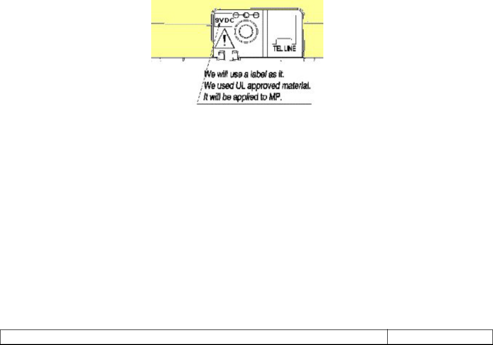
1.6.3.1. AC-DC Adapter Marking
The following information must appear on the AC-DC Adapter:
BELCO INTERNATIONL
CLASS 2 POWER SUPPLY
MODEL NO. : aaaaaaaa
INPUT : 120VAC 60HZ 5W/6W
OUTPUT : 9 VDC 300 mA
MADE IN aaaaaaaaaa
Where AAA is Country Of Origin
The cETLus symbol with control number located near symbol
Plug connection symbol.
In addition, there shall be a caution marking per UL requirement.
CAUTION : RISK OF ELECTRICAL SHOCK. DRY LOCATION USE
ONLY.

3
Written By: Belco International Co., Ltd. PAGE: 5 of 24
1.6.4. Country Of Origin
1.6.4.1. Acceptable Phrase
1.6.4.2. AC-DC Adapter Country of Origin
1.7. STANDARDS & REFERENCES:
FCC and UL Rules and Regulations are mandatory. Other documents are reference.
1.7.1. EIA 470B
Telecommunications - Telephone Terminal Equipment - Performance and
Compatibility Requirements for Telephone Sets with Loop Signalling.
1.7.2. FCC Rules and Regulations
1.7.2.1.47 CFR Part 2
Frequency Allocations and Radio Treaty Matters; General Rules and
Regulations
1.7.2.2.47 CFR Part 15
Radio Frequency Devices
1.7.2.3.47 CFR Part 68
Connection of Terminal Equipment to the Telephone Network
1.7.3. Industry Canada (IC) rules and regulations.
1.7.3.1.CS-03
Standard for Terminal Equipment, Terminal Systems, Network Protection
Devices, Connection Arrangements and Hearing Aid Compatibility
1.7.4. Items not Included in Specification
Any item (measurement parameter or subjective criterion), not included in this
product specification shall be subject to the approval of Bellsouth .
1.8. REGULATORY APPROVALS REQUIRED
This product shall be tested for compliance with all applicable regulatory requirements
listed below. Testing shall be performed, and reports generated by a certified test facility.
1.8.1. FCC Telephone Network Terminal Equipment Registration
The product shall be designed and manufactured so that it may be operated in
accordance with Parts 2, 15, and 68 of FCC Rules and Regulations. The product
shall be filed for FCC registration.

3
Written By: Belco International Co., Ltd. PAGE: 6 of 24
1.8.2. ETL / cETL Approval and Listing
The unit shall be designed and manufactured so that it may be operated in
accordance with UL60950-1.
1.8.3. Industry Canada Approval (IC)
The unit shall be designed and manufactured so that it may be operated in
accordance with the latest revision of the Industry Canada regulations.
1.9. SAFETY
The unit must meet all specifications as set forth in Bellsouth Safety Practices Manual.
The unit must meet any and all applicable UL standards, including UL60950-1. The unit
will be examined by the Bell south Safety Department. In the interest of safety, all
decisions and recommendations of the Department must be incorporated in the design
and manufacture of the unit.
1.10. FACTORY OR AFTER SALES SERVICE INTERFACE
Product service information shall be provided from which Product Field Service Manual
will be generated.
The following items are required in a timely manner to assist the Product Service
department in creating service data.
A) Schematic diagram - on mylar. Schematic must show DC voltages in all modes
of operation for all active devices - or a separate voltage chart drawing may be
submitted.
B) Conductor pattern for each PCB - on mylar
C) Component layout for each circuit board - on mylar. 2 drawings, one to show
components as viewed from conductor side of PCB and one from component
side.
D) Wiring diagram showing interconnection of PCB's and off PCB components such
as LED's, switches, etc.
E) Complete parts list - mechanical and electrical
F) Assembly drawing of complete unit showing cabinet sections, knobs, antenna,
etc.
G) Block diagram of circuit
H) Alignment procedure giving test equipment type, connection information, and
tune up procedure.
I) Pin out drawing of all transistors and IC's.

3
Written By: Belco International Co., Ltd. PAGE: 7 of 24
1.11. COMPATIBILITY
1.11.1. Operation With Other Devices
1.11.2. Operation With Central Offices
This product shall be capable of operating with any FCC/UL approved Central
Office without causing any harm to the Central Office.
1.12. SECURITY CODE INFORMATION
We provide a fixed code that is continuously varied among 1,048,576 discrete digital
codes as each telephone is manufactured.

3
Written By: Belco International Co., Ltd. PAGE: 8 of 24
2. USER INTERFACE DESCRIPTION
2.1. INITIAL FACTORY SETTINGS:
Tone / Pulse Switching: Tone
Volume Control: Nominal ( FCC HAC compatible)
Talk Button: OFF
All LEDs” OFF
2.2. DEFAULT SETTINGS
2.3. RINGING AND TONES:
2.3.1. Warning tone:
Low Battery Indicator: The handset shall provide an audible and visual alert when
its battery charge will soon be inadequate to continue
conversation
Beat 1 2
Time (ms) ON 80
Time (ms) OFF 4000
Beep Frequency (Khz) 2.048
Out of Range Indicator: The handset shall provide an audible and visual alert for 25
seconds when the distance between handset and base
does not permit adequate transmission quality. The last
beat shall be error beep.
Beat 1 2
Time (ms) ON 80 80
Time (ms) OFF 80 4000
Beep Frequency (kHz) 2.048 2.048
2.3.2. Ring:
2.3.2.1 Base unit
2.3.2.1.1 Base Incoming call Ring: Shall meet the para 8.3.3.3.
2.3.2.2.2 Distinctive Ring from CO:
To support telephone-company-supplied Distinctive Ringing features, the
unit ringer(s) shall reproduce ring cadences present on the telephone line,
according to detailed requirements referenced by Distinctive Ring Timing,
in standard specification (para. 8.3.2.3)

3
Written By: Belco International Co., Ltd. PAGE: 9 of 24
2.3.2.2 Handset unit
When the base incoming call will be flash LED and heard beep tone
on handset.
2.3.2.3. Page ring:
This ring will alert the other party to page H/S from B/U for 15seconds.
The page function will operate the ringer of H/S only. This ring shall be
distinctive from incoming call ring.
In case that the handy is low battery or in the out-of range where the
handy is not capable of recieving ID handshake command the base unit
sends, The base unit stops sending the paging data only for 2 seconds.
Time (ms) ON 80 80
Time (ms) OFF 80 730
Beep Frequency (kHz) 2048 2048
2.3.3. Tone Feedback on Key Press
When the base or handset accepts key inputs, appropriate feedback shall be
produced by handset. All feedback tones shall be the same frequency of 2.0 kHz ±
10%.
Tone feedback shall be heard during temporary tone action in pulse mode.
2.3.3.1. Key Tone:
Shall be produced in response to most accepted key presses.
Cadence
Beat 1
Time (ms) On 80
Time (ms) Off ---
2.3.3.2. Confirmation Tone
Shall be produced when a key press is accepted, completing a complex
sequence and altering nonvolatile stored information, such as configuration
settings and repertory dialing entries.
Cadence
Beat 1 2
Time (ms) ON 80 80
Time (ms) OFF 80 --
3
Written By: Belco International Co., Ltd. PAGE: 10 of 24
2.4 DISPLAY:
2.4.2 LED: The following illumination cadences shall indicate that…
Off Indicate that no action is in progress.
On (Solid) Indicate that a steady action in progress.
Slow Blink Warning for temporary stop action or for some change in progress.
a. Low battery:(For the handset)
Blink 1 2
Time (ms) ON 500
Time (ms) OFF 1500
b. Page: (For the base & handset)
Blink 1 2
Time (ms) ON 250 250
Time (ms) OFF 250 250
C. Out-of range
Blink 1
Time (ms) ON 80
Time (ms) OFF 2000
d. Operation status of the talk LED on the base and handy unit when incoming call.
Blink Ring Pause
Time (ms) ON 80 500
Time (ms) OFF 80 500
2.4.3 LEDs on Handset:
Name Description
In use LED LED off if the phone is “on-hook”.
LED on if the phone is “off-hook”.
LED blinking if Page data is incoming from the baseset.
Distinctive and power ring cadence blinking during incoming
call ringing.
Low LED Slow Blinking

3
Written By: Belco International Co., Ltd. PAGE: 11 of 24
2.4.4 LEDs on Base unit:
Name Description
Talk LED LED off if the phone is “on-hook”.
LED on if the phone is “off-hook”.
Distinctive and power ring cadence blinking during incoming
call ringing.
LED fast blinking if Page is pressed (hold mode)
Charge/ Page
LED LED off if the handset is out of the cradle.
LED on if the handset is on the cradle.
LED slow blinking if Page is pressed (on-hook mode)
LED slow blinking if Page is pressed (off-hook mode)
2.5 TEST MODE:
Shall have test mode.
2.6 OPERATING PROCEDURES:
2.6.1 Handset:
The unit shall provide audible feedback when keys are depressed.
# NAME USER INTERFACE NOTE
1 TALK Shall initiate or terminate TALK mode. Toggle between ON and
OFF hook.
When incoming call, press TALK key to accept the call.
When line is not in use, press TALK key to initiate a call.
The unit shall establish a RF link between the base and the
handset. The base shall seize the line, routing audio to and from
the handset. The TALK LED’s shall is on for the baseset and
become steadily lit for the handset respectively.
Auto ON-HOOK:
The unit shall automatically be placed on-hook when the
handset is placed in the charging cradle, or when the
handset has been determined to be Out-of-Range for a
sufficient period of time.
The unit shall be
capable of
automatically
selecting the clearest
available channel
when initiating TALK
mode.
RF link time of 1.5 sec
or less is preferable.
2 Redial/Pause
ON hook - Shall insert a pause in memory dialing sequences
being stored. Pause time shall be 2 seconds.
OFF hook – Shall redial the most recently dialed number in TALK
mode.
During the redial in
tone mode DTMF
tone will be heard
through ear-piece.
3 Channels Automatic Channel Change – The unit shall be capable of
automatically selecting the clearest available channel.
No voice muting.

3
Written By: Belco International Co., Ltd. PAGE: 12 of 24
4 Flash OFF HOOK- Shall initiate a hook switch flash in TALK mode.
ON HOOK- Ring pattern select ion: press Flesh key and
1or ,2,3,4 in on-hook mode
600mS +/- 10%
5 0 to 9 digit
keys
Pressing TALK key, these buttons can be used for manual
dialing. Each key action will
be followed by tone
feedback
6 TONE, * Shall dial or store the ‘*’, in TALK mode respectively. Shall initiate
temporary tone dialing if pulse dial mode is set.
The procedure to activate tone dialing temporarily, for the
purpose of activating touch-tone services offered by banks,
credit card companies, etc. When pulse dialing is selected,
press this button. Then tone dialing shall be active until the unit
is placed on hook. Pulse dialing shall be reselected when the
unit is next taken off hook.
Each key action will be
followed by proper
tone feedback
7 # Shall dial or store the ‘#’, in TALK mode respectively. Each key action will be
followed by proper
tone feedback
8 Ringer on/off
N.A
9 Volume
up/down
Volume up or down function (Talk Mode)
Each “Selection” of the volume up or down switch shall change
13 dB ± 1 dB of volume level. Total volume change shall be 13
dB ± 1dB.
Shall meet FCC HAC
requirement.
10 Talk LED
Hold LED
OFF - the telephone line is not in use, or there is no incoming
call detected
Solid on to indicate “IN USE”.
Blinking - Where the capacity of battery drops below the
threshold, Talk LED is blinking and Alert tone can be heard
through the earpiece
Ring Cadence : Shall indicate the cadence of the ring signal, by
blinking only when ringing voltage is present on line or page
from B/U.

3
Written By: Belco International Co., Ltd. PAGE: 13 of 24
2.6.2 Base unit:
# Function User Interface Note
1 Page Press PAGE key to page the B/S. Ring the H/S for 15
second. Paging will be terminated by pressing PAGE button
on the base again.
Pressing the “talk“key on the hand set will establish RF link.
If handset is off hook, softer ring on handset will alert paging
from Base unit.
2 T/P Switch
Set Tone or Pulse dialing depending on the position of the switch. Mechanical 2 position
switch.
3 Talk LED OFF – neither is the telephone line in use, nor is an incoming ring
detected
Turn on – Telephone is in use
Fast blinking – When the unit is receving an incoming ring.
Ring Cadence - Shall indicate the cadence of the ring signal, by
blinking only when ringing voltage is present on line.
Fast blinking followed by off -> When the handy unit is placed on
its cradle of base unit for id handshaking, For a normal operation
the Talk LED shall be "off" status after fast-blinking
4 Charge/
Page LED
OFF – No charge
ON – Charging of battery in H/S in progress.
Fast blinking per ring sound shall occur during paging.

3
Written By: Belco International Co., Ltd. PAGE: 14 of 24
3 ELECTRICAL SPECIFICATIONS
(More detail the specifications refer to attached – refer A)
3.3 TEST CONDITIONS
Unless otherwise noted, all tests are performed under the following
conditions:
3.3.2.1 Power Supply Voltage:
120Vac ±10% for the base 60Hz.
3.7Vdc ±0.025Vdc for the handset.
3.3.2.2 Ambient Temperature: 25°C ±5°C
3.3.2.3 Standard measurement as described in EIA standard, and 470B.
3.3.2.4 Standard Frequency Modulation: Per vendor’s design
3.4 RF: REFER TO STANDARD SPECIFICATION BELCO INTERNATIONAL
and CONEXANT RF Measurement W138, rev.A.
3.4.2 General
3.4.2.1 Operating freqency range : 2.4048GHz ~2.4750 GHz
3.4.2.2 Operating channels : 40ch (channel table refer to attached – refer B)
3.4.2.3 Modulation type : DBPSK
3.4.2.4 Channel bandwidth: 1.8 MHz
3.4.2.5 Channel frequency : 1ch : 2.4048 GHz
20ch : 2.4408 GHz
40ch : 2.4750 GHz
3.4.2.6 Receiver sensitivity : -98dBm @ I/Q=220mV + 40mV,
Vagc= 1.5V+ 0.1V
3.4.2.7 Symbol Rate : 1.2M bps
3.4.2.8 Speech codec : ADPCM (32 Kbps )

3
Written By: Belco International Co., Ltd. PAGE: 15 of 24
3.4.2.9 Transmitted Power
3.4.2.9.1 Peak Power
Channel Peak Power level (dBm)
No Ch Frequency(GHz) High Medium Low
1 2.4048
20 2.4408
39 2.4750
16 +/- 2
5 +/- 2
-6.5 +/- 2
Note: Peak power readings using the HP8990A Peak power analyzer
3.4.2.9.2 Normal TX Power(High mode) : 14 +/- 3dBm (spectrum analyzer)
3.4.2.10 Radiated emission : see FCC 15.249 for limits
3.4.2.11 Audio distortion : < 5%
3.4.2.12 Audio freq response : 300Hz ± 3dB
3KHz ± 30dB
3.4.2.13 AM Hum noise & Noise : < 35dB
3.4.2.14 Range test : More than 400ft

3
Written By: Belco International Co., Ltd. PAGE: 16 of 24
3.5 LINE INTERFACE:
The set shall meet all items in the Belco. The following items will be tested during the
evaluation.
3.5.2 Battery Requirements
3.5.2.1 The batteries must supply 2.0 hours (above) of continuous talk time at low
power operation or more than 14 days of stand-by service when fully charged.
3.5.2.2 The unit must be fully charged within 3.5 hours at 120 Vac from the fully
discharged condition. There shall be every precaution in charging circuit
design to extend the battery life and reduce adverse battery capacity memory
effect of Lithium-ion Polymer battery.
3.5.2.3 The external contacts, on the handset used for recharging the battery, must be
protected, such that when shorted together the battery is not discharged.
3.5.2.4 In the Off-Hook mode, the handset shall beep at 30 second interval to
inform the user when the battery voltage has dropped to a level that could
impair the quality of the communication link if usage is prolonged
without recharging the handset battery.
The battery voltage shall be considered low when in the range of 3.1V to
3.3VDC (3.2V DC nominal)
3.5.3 Off Hook Time
From the time that the hand set is lifted from the cradle if unit is in Auto Standby,
or when the TALK button is pressed if not in Auto Standby, until the base unit
goes OFF HOOK shall be less than 1.5 sec.
3.5.4 DTMF and Pulse dialing: Shall meet the para. 8.5.5 to 8.5.21.
3.5.5 Dial Pulse Mute (Para. 8.5.22)
The speaker output due to pulse dialing shall be less than 72 dB SPL ± 12 dB.
3.5.6 Tone Feedback on Key Depression
In pulse dial, depression of any key shall produce a tone at the ringer buzzer with
the following characteristics:
Frequency: 2000Hz ± 10%
Wave form: Square Wave
Duration: 80 ms fixed
Output Level: 105 ± 5db SPL at earpiece
In tone dial, the tone shall be true DTMF feedback. In standby mode the PAGE
key on the base unit and TALK key on the handset unit when depressed shall
produce the above tone.

3
Written By: Belco International Co., Ltd. PAGE: 17 of 24
3.5.7 Tone Ringer (Base unit only)
The ringer shall be of the tone type, meeting the following specifications.
Component Parameter Min Max Units
Output level at ringer 110 dB SPL
Output level at 0.5 meter 68 dB SPL
3.5.8 Ring Sensitivity: Shall meet the para. 8.3.2 and 8.3.3.
3.5.9 On-Hook DC and AC impedance: Shall meet the para. 8.3.4 and 8.3.5.
3.5.10 OFF- hook Impedance: Shall meet the para. 8.3.6.
3.5.11 Buffer Size©
The redial buffer shall be capable of holding (and redialing) strings of at least
32digits.
3.5.12 Audio:
3.5.12.1 Buzz and Static noise: There shall be no buzzing or static sound from the
receiver.
3.5.12.2 Fading and Drop out: There shall be no audio fading or audio drop out when
user turns against a fixed location of the base unit in any direction.
3.5.12.3 Objective Loudness Ratings
( We need Confirm or specification – This model is earset Type )
The phone shall meet the following OLR limits over the range of loop condition
as following
0 kft 9 kft 15 kft
TOLR - 40 to - 53 - 38 to - 51 - 36 to - 49
ROLR 41 to 51 43 to 53 45 to 55
SOLR 14 to -2 16 to -1 17 to 0
Measurement procedures, please refer to EIA-470B standards.
3.5.12.4 Volume Control: Shall meet the HAC requirement.
change volume switch UP key shall increase the volume in 13 dB ± 1dB.

3
Written By: Belco International Co., Ltd. PAGE: 18 of 24
4 ENVIRONMENTAL
This product shall comply with BELCO General Specifications and Procedures for Telephone
Products, with the following exceptions and additions:
4.3 PURPOSE OF SPECIFICATION
To assure product can still meet customer expectations after and during exposure to
expected environmental use conditions.
4.4 TEMPERATURE PERFORMANCE
4.4.2 Operating Range
Base unit and Handset: 0°C to +50°C
4.4.3 FCC Performance (Reference Para 15.233(G) of FCC Rules)
Base unit and Handset: -40°C to +66°C for frequency stability.
4.5 ELECTROSTATIC DISCHARGE
Shall meet the Paragraph 6.3.2 of Standard Specification for Communication Products,
BELCO.
4.6 HUMIDITY:
The D.U.T. will be subjected to a 2 week humidity cycle test as follows:
• 4 days---90% relative humidity @ 40 deg. C then
• 3 days---12% relative humidity @ 50 deg. C then
• 4 days---90% relative humidity @ 40 deg. C then
• 3 days---12% relative humidity @ 50 deg. C
After the humidity cycle above, there must be no functional, performance, or appearance
degradation.

3
Written By: Belco International Co., Ltd. PAGE: 19 of 24
FCC REGULATIONS
Warning : Modifying or tampering with the telephone’s internal components can cause a malfunction
and might invalidate the telephone’s warranty and void your FCC authorization to operate it. If the
trouble is harming the telephone lines, the telephone company might ask you to disconnect the
telephone until you have resolved the problem.
As it complies with Part 68 of the FCC rules and the technical requirements for connection to telephone
networks published by ACTA, your unit has been registered with the FCC. The FCC requires us to
provide you with the following information :
1. Connection and use with the nationwide telephone network :
The FCC requires that you connect to a nationwide telephone network through a modular telephone
outlet which is TIA/EIA-IS-968 compliant. It is USOC jack type RJ11C.
This equipment may not be used on coin service provided by the telephone company. Connection to
party lines is subjected to state tariffs. Check with your local telephone company.
2. Notification to the telephone company :
FCC rules require that upon request you provide the following information to the phone company.
A. The line (telephone number) to which you will connect the telephone equipment, and
B. The Registration Number and Ringer Equivalence Number (REN). These numbers are found on the
back or bottom of your telephone equipment.
The REN is useful to determine the quantity of devices you may connect to your telephone line and
still have all of those devices ring when your telephone number is called. In most, but not all areas, the
sum all RENs should be 5 or less. To determine the number of devices permitted in your area, contact
your local telephone company.
3. Repair instructions :
If it is determined that your telephone equipment is malfunctioning, the FCC requires that it not be
used and be used and be unplugged from the modular outlet until the problem has been corrected.
Repairs to this telephone equipment can be made only by the manufacturer or its authorized agents,
or by others who may be authorized by the FCC. Unauthorized repairs void registration and warranty.
4. Rights of the telephone company :
If your product is causing harm to the telephone network, the telephone company may temporarily
discontinue your service. If possible, they will notify you in advance. But if advance notice isn’t
practical, you will be given the opportunity to correct the problem, and you will be informed of your
right to file a compliant with the FCC. Your telephone company may make changes in its facilities,
equipment, operations or procedures that could affect the proper functioning of your telephone
equipment. If such changes are planned, you will be notified in advance.
5. This product is compatible with inductively coupled hearing aids.
Note: This applies only if this product is equipped with a corded or cordless handset.
6. Programmimg / testing emergency numbers:
When programmimg emergency numbers and/or making test calls to emergency numbers
A. Remain on the line and briefly explain to the dispatcher the reason for the call before hanging up.
B. Perform such activities in the off-peak hours, such as early morning or late evening.

3
Written By: Belco International Co., Ltd. PAGE: 20 of 24
FCC REGULATIONS CONTINUED
INTERFERENCE INFORMATION: PART15 OF FCC RULES
Some telephone equipment generates and uses radio frequency energy which if not properly installed,
may cause interference to radio and television reception.
This unit has been tested and found to comply with the limits for class B computing device in accordance
with the specifications in Part 15 of the FCC rules. These specifications are designed to provide
reasonable protection against such interference in a residential installation. However, there is no
guarantee that interference will not occur in a particular installation.
If this equipment does cause interference to radio or television reception, when it’s in use, the user is
encouraged to try correct the interference by one or more of the following measures:
A. Where it can be done safely, reorient the radio or TV receiving antenna.
B. To the extent possible, relocate the television, radio, or other receiver with respect to the telephone
equipment.
C. If your telephone product runs on AC power, plug your product into an AC outlet that’s not on the
same circuit as the one used by the radio or television.
This device complies with Part15 of the FCC rules. Operation is subject to
the following two conditions : (1) This device may not cause harmful interference,
and (2) This device must accept any interference received, including interference
that may cause undersired operation. Privacy of communications may not be
ensured when using this phone.

3
Written By: Belco International Co., Ltd. PAGE: 21 of 24
IC REGULATIONS
Notice : This equipment meets the applicable Industry Canada Terminal Equipment Technical
Specifications. This is confirmed by the registration number. The abbreviation, IC, before the registration
number signifies that registration was performed based on a Declaration of Conformity indicating that
Industry Canada technical specifications were met. It does not imply that Industry Canada approved the
equipment.
Before installing this equipment, users should ensure that it is permissible to be connected to the
facilities of the local telecommunications company. The equipment must also be installed using an
acceptable method of connection. The customer should be aware that compliance with the above
conditions may not prevent degradation of service in some situations.
Repairs to certified equipment should be coordinated by a representative designated by the supplier.
Any repairs alterations made by the user to this equipment, or equipment malfunctions, may give the
telecommunications company cause to request the user to disconnect the equipment.
Users should ensure for their own protection that the electrical ground connections of the power utility,
telephone lines and internal metallic water pipe system, if present, are connected together. This
precaution may be particularly important in rural areas.
Caution: Users should not attempt to make such connections themselves, but should contact the
appropriate electric inspection authority, or electrician, as appropriate.
Notice: The Ringer Equivalence Number (REN) assigned to each terminal device provides an indication
of the maximum number of terminals allowed to be connected to a telephone interface. The termination
on any interface may consist of Ringer Equivalence Numbers of all the device does not exceed 5.
Privacy of communications may not be ensured when using this telephone.
Interference Information
Operation is subject to the following two conditions : (1) this device may not cause interference, and (2)
this device must accept any interference, including interference that may interference, including
interference that may cause undesired operation of the device.

3
Written By: Belco International Co., Ltd. PAGE: 22 of 24
AVIS D’INDUSTRIE CANADA
Avis : L’étiquette d’Industrie Canada identifie le matériel homologué. Cette homologation signifie que
l’équipement est conforme à certaines exigences de protection, de fonctionnement et de sécurité du
réseau de communication qui apparaissent dans les documents appropriés traitant des exigencies
techniques des équipements de terminaison. Industrie Canada n’atteste pas que I’équipement donnera
satisfaction à l’usager.
Avant d’installer cet équipement, l’usager doit s’assurer qu’il lui est permis de le connecter aux
installations de son enterprise de téléphone et il doit utiliser une méthode de raccordement acceptable.
Le client doit savoir que le fait de se conformer aux conditions ci-dessus ne peut empêcher la
dégradation du service dans certaines conditions.
Les réparations de l’équipement homologué doivent être coordonnées par un représentant désigné du
fournisseur. Toute réparation ou modification de cet appareil effectuée par l’usager ou tout mauvais
fonctionnement de l’équipement peut donner à l’entreprise de téléphone des raisons de demander à
l’usager de déconnecter l’équipement.
Pour sa propre protection, l’usager doit s’assurer que les mises à la terre de l’équipement électrique, du
systéme téléphonique et de l’entrée d’eau, le cas échéant, soient connectées ensemble. Cette
précaution est particuliérement importante dans les zones rurales.
Mise en garde : L’usager ne doit pas essayer d’effectuer lui-même de telles connexions, mais devrait
contacter un inspecteur compétent ou un électricien qualifié.
Avis : Le numéro d’équivalence sonnerie (NES) attribué à chaque appareil permet de connaître le
nombre maximum d’appareils pouvant être raccordés sur une ligne téléphonique. Le total des NES de
tous les appareils connectés sur une ligne ne doit pas dépasser 5.
Lorsque cet appareil est utilisé, il est impossible de garatir la confidentialité des conversations.
Renseignements concernant les interférences
L’utilisation de cet appareil est premise aux deux conditions suivantes : (1) il ne doit pas causer
d’interférences et (2) il doit accepter d’interférences, y compris celles qui peuvent nuire à son
fonctionnement.

3
Written By: Belco International Co., Ltd. PAGE: 23 of 24
IMPORTANT SAFETY INSTRUCTIONS
When using this product, basic safety precautions should always be followed to reduce the risk of fire,
electrical shock, and injury to persons, including the following:
1. Read and understand all instructions.
2. Follow all warnings and instructions marked on the product.
3. Unplug this product from the wall outlet before cleaning. Do not use liquid cleaners, or aerosol
cleaners. Use a damp cloth for cleaning
4. Do not use this product near water, for example near a bathtub, wash bowl, kitchen sink, or laundry
tub, in a wet basement, or near a swimming pool.
5. Do not place this product on an unstable cart, stand or table .The product may fall, causing serious
damage to the product.
6. Slots and openings in the cabinet back or bottom are provided for ventilation. To protect it from
overheating, these openings must not be blocked or covered. The openings should never be
blocked by placing the product on the bed, sofa, rug or other similar surface. This product should
never be placed near or over a radiator or heat register. This product should not be placed in an
enclosed environment unless proper ventilation is provided.
7. Do not allow anything to rest on the power cord. Do not locate this product where the cord will be
abused by animals or persons walking on it.
8. Do not overload wall outlets and extension cords as this can result in risk of fire or electrical shock.
9. Never push objects of any kind into this product through cabinet slots as they may touch dangerous
voltage points or short out parts that could result in a risk of fire of electrical shock. Never spill liquid
of any kind on the product.
10. To reduce the risk of electric shock, do not disassemble this product. Instead take it to a qualified
service person when service or repair work is required. Opening or removing covers may expose
you to dangerous voltages or other risks. Incorrect re-assembly can cause electrical shock when the
appliance is subsequently used.
11. Unplug all cords and refer servicing to qualified service personnel under the following conditions:
A. When the power supply cord or plug is damaged or frayed.
B. If liquid has been spilled into the product.
C. If the product has been exposed to rain or water.
D. If the product does not operate normally by following the operating instructions. Adjust only those
controls covered in the operating instructions. Improper adjustment of other controls may result in
damage and require work by a qualified technician to restore the product to normal operation.
12. Avoid using a telephone (other than a cordless type) during an electrical storm. There may be a
remote risk of electrical shock from lightning.
13. Do not use the telephone to report a gas leak in the vicinity of the leak.
SAVE THESE INSTRUCTIONS

3
Written By: Belco International Co., Ltd. PAGE: 24 of 24
CONSIGNES DE SÉCURITÉ IMPORTANTES
Pour réduire les risques de blessure, d’incendie et d’électrocution, chaque fois que vous utilisez ce
produit, appliquez les règles élémentaires de sécurité, notamment les suivantes :
1. Lisez attentivement toutes les instructions.
2. Respectez tous les avertissements et toutes les instructions apparaissant sur le produit.
3. Avant de nettotyer ce produit, débranchez le prise murale. N’utilisez pas de nettoyant liquide ni en
aérosol.
Pour nettoyer, utilisez simplement un chiffon humide.
4. N’utilsez jamais ce produit près d’un point d’eau (par exemple, près d’une baignoire, d’une cuvette de
lavage, d’un évier de cuisine ou d’un lavado), dans un sous-sol humide ou près d’une piscine.
5. Ne placez pas ce produit sur une table, un meuble ou un chariot instable. Si le produit tombe, il
risque d’être gravement endommagé
6. Les fentes et les ouvertures qui se trouvent derrière ou dessous l’appareil servent à la ventilation.
Pour éviter toute surchauffe, ces ouvertures ne doivent jamais être couvertes ou obstruées. Pour
éviter qu’elles soient bloquées, ne placez pas le produit sur un lit, un sofa, une moquette ou une
autre surface molle. Ce produit ne devrait jamais être placé près d’un radiateur ou d’un autre
appareil de chauffage. Ce produit ne doit jamais être placé dans en endroit confiné sauf si une
ventilation adéquate est prévue.
7. Ne laissez jamais d’objet posé sur le cordon d’alimentation. Ne placez pas ce produit à un endroit où
le cordon risque d’être abÎmé par des animaux de compagnie ou des personnes pouvant l’écraser
en marchant.
8. Ne surchargez jamais les prises murales et les rallonges car vous risqueriez alors de provoquer un
incendie ou une électrocution.
9. Ne faites jamais entrer des objets par les fentes du boîtier de cet appareil car vous pourriez toucher
des points de tension dangereux ou causer un court-circuit pouvant entraîner un incendie ou une
électrocution. Il ne faut jamais verser de liquide sur ce produit.
10. Pour réduire les risques d’électrocution, ne tentez pas de démonter ce produit. Lorsqu’une
réparation semble nécessaire, apportez-le plutôt chez un technicien qualifié. Si vous ouvrez ou
enlevez une pièce du boîter, vous vous exposez à des tensions électriques dangereuses et à
d’autres risques. Si l’appareil est mal assemblé, une électrocution pourrait survenir lors de la
prochaine utilisation.
11. Dans les situations suivantes, débranchez tous les cordons d’alimentation et consultez un technicien
qualifié.
A. Lorsque le cordon d’alimentation est endommagé ou effiloché.
B. Lorsqu’un liquide a été renversé sur le produit.
C. Lorsque le produit a été exposé à la pluie ou à l’eau.
D. Lorsque le produit ne fonctionne pas normalement et que toutes les instructions ont été suivies.
Ne réglez que les commandes décrites dans le guide d’utilisation. Un mauvais réglage des autres
commandes peut causer des dommages, et l’intervention d’un technicien qualifié pourrait être
nécessaire pour remettre le produit en état.
12. Évitez d’utiliser un téléphone (sauf un téléphone sans fil) durant un orage électrique. Il exists alors
des risques faibles d’électrocution par un éclair.
13. S’il y a une fuite de gaz, n’avisez pas les autorités avec un téléphone situé près de la fuite.

BELCO INTERNATIONAL CO., LTD.
212, YEOKGOK-DONG, WONMI-KU, BUCHEON CITY, KYUNGKI-DO, KOREA
TEL: 82-32-349-1903 FAX: 82-32-349-1907 E-MAIL : diana@belco.co.kr
Security code information
We provide a fixed code that is continuously varied among 1,048,576 discrete digital codes as
each telephone is manufactured.