Belkin DXNRUTER Dynex Wireless N Router User Manual 12
Belkin International, Inc. Dynex Wireless N Router 12
Belkin >
User Manual

USER GUIDE
Wireless N Router
DX-NRUTER

2Contents
Dynex DX-NRUTER
Wireless N Router
Contents
Introduction ......................................................................................2
Product features................................................................................3
Setting up your wireless router..........................................................8
Troubleshooting ..............................................................................55
Legal notices ...................................................................................67
One-Year Limited Warranty .............................................................69
Introduction
Thank you for purchasing the Dynex DX-NRUTER Wireless N Router. The easy installation and
setup will have you networking wirelessly in minutes. Be sure to read through this User Guide
completely, and pay special attention to the section entitled “Product features” on page 3.
Benefits of a home network
Your home network will let you:
• Share one high-speed Internet connection with all the computers in your home
• Share resources, such as files, and hard drives among all the connected computers in
your home
• Share a single printer with the entire family
• Share documents, music, video, and digital pictures
• Store, retrieve, and copy files from one computer to another
• Simultaneously play games online, check Internet e-mail, and chat
Advantages of a wireless network
Here are some of the advantages of setting up a Dynex wireless network:
•Mobility–You will no longer need a dedicated “computer room”— now you can work
on a networked laptop or desktop computer anywhere within your wireless range.
•Easy installation–Dynex’s Setup Assistant makes setup simple.
•Flexibility–Set up and access printers, computers, and other networking devices
from anywhere in your home.
•Easy expansion–The wide range of Dynex networking products lets you expand your
network to include devices such as printers and gaming consoles.
•No cabling required–You can spare the expense and hassle of retrofitting Ethernet
cabling throughout the home or office.

Product features 3
•Widespread industry acceptance–Choose from a wide range of interoperable
networking products.
•N wireless technology–Your router uses a new smart-antenna technology called
Multiple Input Multiple Output (MIMO). N wireless complies with the IEEE draft
802.11n specification. It increases speed, range, reliability, and spectral efficiency for
wireless networking systems.
Product features
In minutes you will be able to share your Internet connection and network your computers.
The following is a list of features that make your router an ideal solution for your home or
small office network.
Works with Both PCs and Mac® Computers—Your router supports a variety of
networking environments including Mac OS® X v10.x, Linux®, Windows® 98,
Windows® 2000, Windows XP®, Windows Vista®, and others. All that is needed is an Internet
browser and a network adapter that supports TCP/IP (the standard language of the Internet).
Front-Panel LED Display—Lighted LEDs on the front of your router indicate which
functions are in operation. You’ll know at-a-glance whether your router is connected to the
Internet. This feature eliminates the need for advanced software and status-monitoring
procedures.
Web-Based Advanced User Interface—You can set up your router’s advanced functions
easily through your Web browser, without having to install additional software onto the
computer. There are no disks to install or keep track of and you can make changes and
perform setup functions from any computer on the network quickly and easily.
NAT IP Address Sharing—Your router employs Network Address Translation (NAT) to share
the single IP address assigned to you by your Internet Service Provider while saving the cost
of adding IP addresses to your Internet service account.
SPI Firewall—Your router is equipped with a firewall that will protect your network from a
wide array of common hacker attacks including IP Spoofing, Land Attack, Ping of Death
(PoD), Denial of Service (DoS), IP with zero length, Smurf Attack, TCP Null Scan, SYN flood,
UDP flooding, Tear Drop Attack, ICMP defect, RIP defect, and fragment flooding.
Integrated 10/100 4-Port Switch—Your router has a built-in, 4-port network switch to
allow your wired computers to share printers, data and MP3 files, digital photos, and much
more. The switch features automatic detection so it will adjust to the speed of connected
devices. The switch will transfer data between computers and the Internet simultaneously
without interrupting or consuming resources.
Universal Plug-and-Play (UPnP) Compatibility—UPnP (Universal Plug-and-Play) is a
technology that offers seamless operation of voice messaging, video messaging, games, and
other applications that are UPnP-compliant.
Support for VPN Pass-Through—If you connect to your office network from home using
a VPN connection, your router will allow your VPN-equipped computer to pass through your
router and to your office network.

4Product features
Built-In Dynamic Host Configuration Protocol (DHCP)—Built-In Dynamic Host
Configuration Protocol (DHCP) on-board makes for the easiest possible connection of a
network. The DHCP server will assign IP addresses to each computer automatically so there is
no need for a complicated networking setup.
Setup Assistant—The Setup assistant takes the guesswork out of setting up your router.
This automatic software determines your network settings for you and sets up your router for
connection to your Internet Service Provider (ISP). In a matter of minutes, your router will be
up and running on the Internet.
Note: Setup Assistant software is compatible with Windows 2000, Windows XP,
Windows Vista, and Mac OS X 10.x. If you are using another operating system, your router
can be set up using the Alternate Setup Method described in this User Guide (see
“Alternative setup method” on page 16.
Integrated N Wireless Access Point—N MIMO is an exciting new wireless technology
based on the draft IEEE 802.11n specification. It employs MIMO (Multiple Input Multiple
Output) smart-antenna technology that achieves data rates up to 300 Mbps. Actual
throughput is typically lower than the connected data rate and will vary depending on your
networking environment.
Note: The standard transmission rate of 270 Mbps is the physical data rate. Actual data
trhoughput will be lower.
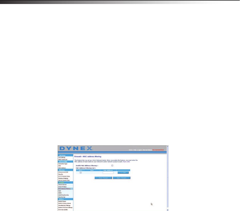
MAC Address Filtering—For added security, you can set up a list of MAC addresses (unique
client identifiers) that are allowed access to your network. Every computer has its own MAC
address. Simply enter these MAC addresses into a list using the Web-Based Advanced User
Interface and you can control access to your network.
Package contents
• Dynex N Wireless Router
• Quick Installation Guide
• Installation software CD
• RJ-45 Ethernet cable
• Power supply
• User Guide on Setup Assistant CD
System requirements
• Broadband Internet connection such as a cable or DSL modem with RJ45 (Ethernet)
connection
• At least one computer with an installed network interface adapter
• TCP/IP networking protocol installed on each computer
• RJ-45 Ethernet networking cable
• Internet browser
Product features 5
Setup Assistant software system requirements
• A computer running Windows 2000, Windows XP, or Windows Vista or running
Mac OS X v10.x
• Minimum 1 GHz processor and 128 MB RAM
• Internet browser
Components
Your router has been designed to be placed on a desktop. All of the cables exit from the rear
of your router for better organization and utility. The LED indicators are easily visible on the
front of your router to provide you with information about network activity and status.
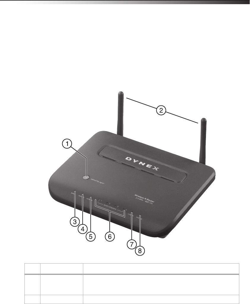
Front panel
# Component Description
1 Security Sync button Push and hold this button for three seconds, then initiate the Security Sync (WPS)
procedure on the client device within two minutes. Your client will automatically
exchange the security information and be added to your wireless network.
2 Antenna Lets your router communicate with a wireless client (card or USB adapter).

6Product features
3 Power/ready LED When you apply power to your router or restart it, a short period of time elapses
while your router boots up. During this time, the Power/Ready LED blinks. When
your router has completely booted up, the Power/Ready LED becomes a SOLID light,
indicating your router is ready for use.
Off—Router is off
Blinking Green—Router is booting up
Solid Green—Router is ready
4 Security Sync LED Lights to indicate that WPS has been activated.
Blinking Green—Your router is searching for a WPS client to connect with.
Solid Green—The secure connection has been established with the client.
5 Wireless network LED Off—The wireless network is off
Solid Green—The wireless network is ready
Blinking Green—Network activity
6 Wired computer
status LEDs
These LEDs are labeled 1-4 and correspond to the numbered ports on the rear of your
router. When a computer is properly connected to one of the wired computer ports
on the rear of your router, the LED will light.
Off—The wireless network is off
Solid Green—A 10base-T device is connected
Solid Orange—A 100base-T device is connected
Blinking—Port activity
7 Modem status LED This LED lights green to indicate that your modem is connected properly to your
router. It blinks rapidly when information is being sent over the port between your
router and the modem.
Off—No WAN link
Solid Green—Good WAN link
Blinking Green—WAN activity
8 Internet LED This unique LED shows you when your router is connected to the Internet. When the
light is OFF, your router is not connected to the Internet. When the light is blinking,
your router is attempting to connect to the Internet. When the light is solid green,
your router is connected to the Internet. When using the “Disconnect after x
minutes” feature, this LED becomes extremely useful in monitoring the status of
your router’s connection.
Off—Router is not connected to the Internet
Blinking Green—Router is attempting to connect to the Internet
Solid Green—Router is connected to the Internet
# Component Description
Product features 7
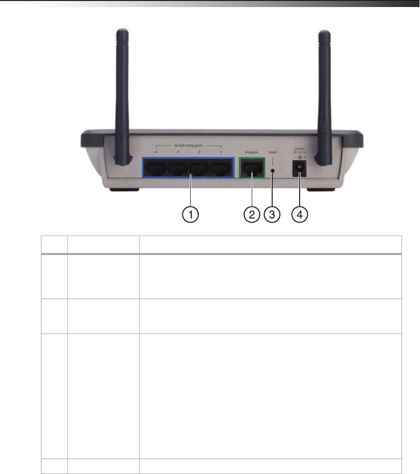
Back panel
# Component Description
1 Wired computer
ports - Blue
Connect your wired (non-wireless) computers to these ports. These ports are RJ-45,
10/100 auto-negotiation, auto-uplinking ports for standard UTP category 5 or 6
Ethernet cable. The ports are labeled 1 through 4. These ports correspond to the
numbered LEDs on the front of your router.
2 Modem port - Green This port is for connection to your cable or DSL modem. Use the cable that was
provided with the modem to connect the modem to this port. Use of a cable other
than the cable supplied with the cable modem may not work properly.
3 Reset button The Reset button is used in rare cases when your router may function improperly.
Resetting your router restores your router’s normal operation while maintaining the
programmed settings. You can also restore the factory default settings by using the
Reset button. Use the restore option in instances where you may have forgotten your
custom password.
Resetting your router—Push and release the Reset button. The lights on your
router will momentarily flash. The Power/Ready light will begin to blink. When the
Power/Ready light becomes solid again, the reset is complete.
Restoring the Factory Defaults—Press and hold the Reset button for at least 10
seconds, then release it. The lights on your router will momentarily flash. The
Power/Ready light will begin to blink. When the Power/Ready light becomes solid
again, the restore is complete.
4 Power jack The 5 V DC power supply plugs into this jack.

8Setting up your wireless router
Setting up your wireless router
Modem requirements
Your cable or DSL modem must be equipped with an RJ-45 Ethernet port. Many modems
have both an RJ-45 Ethernet port and a USB connection. If you have a modem with both
Ethernet and USB, and are using the USB connection at this time, you will be instructed to
use the RJ-45 Ethernet port during the installation procedure. If your modem has only a USB
port, you can request a different type of modem from your ISP, or you can, in some cases,
purchase a modem that has an RJ-45 Ethernet port on it.
Important: Always install your router first! if you are installing numerous network devices
for the first time, it is important that your router is connected and running before
attempting to install other network components such as notebook cards and desktop
cards.
Setup assistant
Dynex has provided our Setup Assistant software to make installing your router a simple and
easy task. You can use it to get your router up and running in minutes. The Setup Assistant
requires that your computer be connected directly to your cable or DSL modem and that the
Internet connection is active and working at the time of installation. If it is not, you must use
the “Alternative setup method” section on page 16 to configure your router. Additionally, if
you are using an operating system other than Windows 2000, Windows XP, Windows Vista, or
Mac OS X v10.x, you must set up your router using the “Alternative setup method” section on
page 16.
Hardware connections
To connect the hardware:
1Unplug your modem's power cord. Put your router next to the modem and raise your
router’s antenna.
2Locate the networking cable that connects your modem and computer. Unplug that
cable from your modem, and plug it into any gray port on the back of your router.
3Find your new networking cable (included in the box with your router) and connect it
to the yellow port on the back of your router. Connect the other end to your modem, in
the port that is now free.
4Plug in your modem's power cord. Wait 60 seconds for the modem to start up. Plug
your router’s power supply into the black port on the back of your router. Plug the
other end into the wall outlet.
5Wait 20 seconds for your router to start up. Look at the display on the front of your
router and make sure the Wired and Router icons are lit up in green. If they are not,
recheck your connections.
Setting up your wireless router 9
Running the Setup Assistant
To run the Setup Assistant:
1Shut down any programs that are running on your computer at this time.
2Turn off any firewall or Internet-connection-sharing software on your computer.
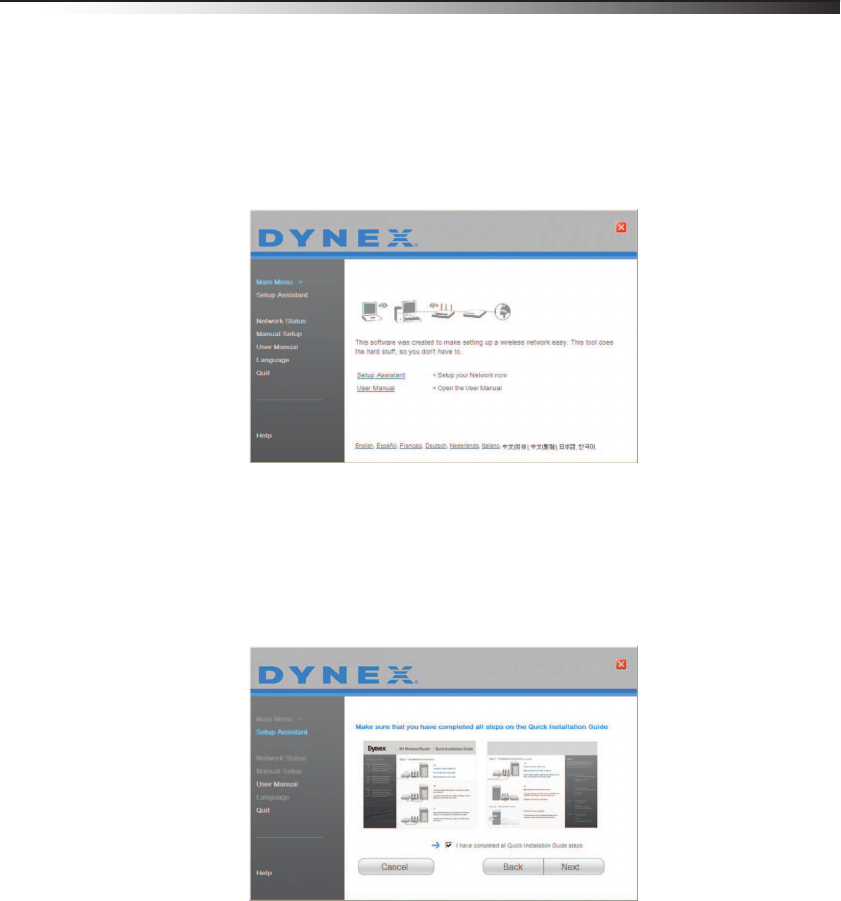
3Insert the included CD into your computer. The Setup Assistant will automatically
appear on your computer's screen within 15 seconds. Click GO to run the Setup
Assistant, then follow the on-screen instructions.
Important: Run the Setup Assistant from the computer that is directly connected to your
router.
Note for Windows users: If the Setup Assistant does not start up automatically, select your
CD drive from My Computer and double-click the file named SetupAssistant to start
the Setup Assistant.
4When the Confirmation screen opens, verify that you have completed all QIG steps by
checking the box to the right of the arrow, then click Next to continue.
10 Setting up your wireless router
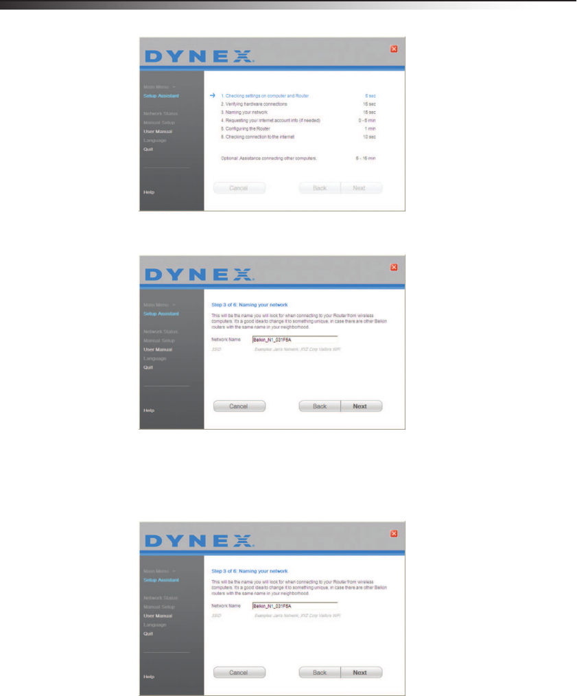
Setup Assistant will indicate each time a step in the setup has been completed.
When it is time to name your network, the Setup Assistant will open the Naming your
network screen.
The default wireless network name or Service Set Identifier (SSID) is the name of your
wireless network that your computers or devices with wireless network adapters will
connect to.
5You can either accept the default name or change it to something unique. If you
change it, write down the name for future reference. Click Next to continue.
Setting up your wireless router 11
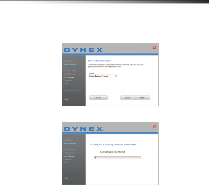
6If your Internet account requires a login and password, you will be prompted with a
screen similar to the illustration above. Select your country or ISP from the lists.
The Setup Assistant will now configure your router by sending data to your router and
restarting it. Wait for the on-screen instructions.
Caution: Do not disconnect any cable or power off your router while your router is rebooting.
Doing so will render your router inoperable.
After configuring your router, the Setup Assistant checks your connection to the
Internet.
12 Setting up your wireless router
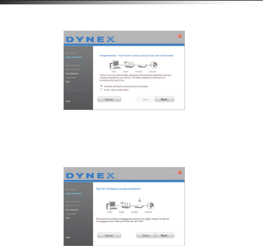
This completes your router installation. You will see the Congratulations screen when
your router can connect to the Internet. You can begin surfing by opening your
browser and going to any Web site.
7You can use the Setup Assistant to set up your other wired and wireless computers to
connect to the Internet by clicking Next. If you decide to add computers to your router
later, select Exit the Assistant, then click Next.
Troubleshooting the setup
To troubleshoot the setup:
• If the Setup Assistant is not able to connect to the Internet, you will see the following
screen. Follow the on-screen instructions to go through the troubleshooting steps.
Setting up your wireless router 13
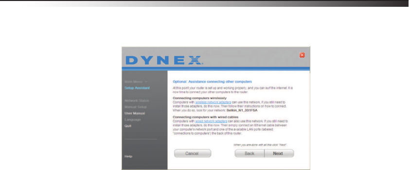
To use the optional assistance to connect to other computers:
1This optional step will help you to connect additional wired and wireless computers to
your network. Follow the on-screen instructions.
At this point, your router is set up and working properly. It is now time to connect your other
computers.
Connecting computers wirelessly
Computers with wireless network adapters can use this network. If you still need to install
those adapters, do this now. Then follow their instructions on how to connect. When you do
so, look for your network: John's Home Wi-Fi.
Connecting computers with wired cables
Computers with wired network adapters can use this network. If you still need to install
those adapters, do this now. Then connect an Ethernet cable between your computer's
network port and one of the available LAN ports (labeled connections to computers) on
the back of your router.]
Once you have verified that your other wired and wireless computers are properly connected,
your network is set up and working. You can now surf the Internet. Click Next to go back to
the main menu.
14 Setting up your wireless router
Wireless security setup
Make sure that your complete the basic setup of your router before setting up security. Make
sure that all of your computers (wired and wireless) can successfully connect to the Internet
through your router.
To set up security:
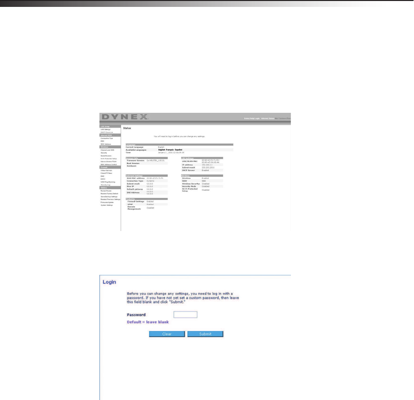
1On a computer that has a wired (cable) connection to your router, open a Web browser.
In the address field, type 192.168.2.1 (or the IP address you customized), then click
Enter.
2In the menu at left, go to the wireless section and click Security.
If asked to log in, enter your password. or if you have not yet set a custom password,
leave this field blank. Then click, Submit.
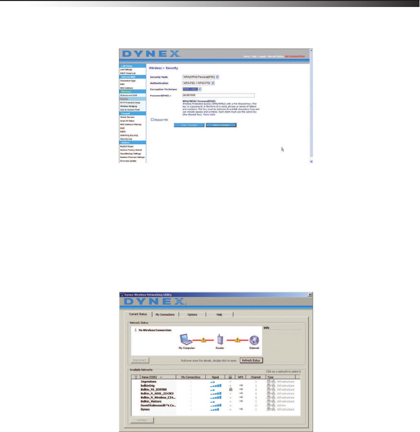
Setting up your wireless router 15
3You will be asked to pick a security type. We recommend WPA2-PSK as the security
mode and then WPA-PSK+WPA2-PSK as the Authentication, as it is the most secure
and easiest to use. Once you have made your choice, click Apply Changes.
4In the Pre-shared key field, type a security key that is easy for you to remember. Using
some punctuation will increase your network's security (for example, “My favorite
team is the Tigers!”). Click Apply Changes.
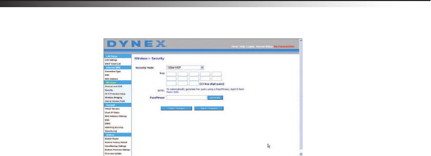
5Now go to each of your wireless computers. Use the wireless utility software on each to
do the following (see you wireless adapter's user manual for more detailed
instructions):
a. Find your wireless network and connect to it.
b. When prompted, enter the phrase you created above.
Note: If a computer does not accept the phrase, it likely does not yet support WPA/WPA2. Go
to your wireless adapter manufacturer's Web site and check for a driver update.
16 Setting up your wireless router
6If you do not want to update your computer's wireless adapter to work with
WPA/WPA2, return to Step 4 and choose WEP.
Alternative setup method
The Web-Based Advanced User Interface is a Web-based tool that you can use to set up your
router if you do not want to use the Setup Assistant. You can also use it to manage advanced
functions of your router. From the Web-Based Advanced User Interface, you can perform the
following tasks:
• View your router’s current settings and status
• Configure your router to connect to your ISP with the settings that they provided you
• Change the current network settings such as the Internal IP address, the IP address
pool, DHCP settings, and more
• Set your router’s firewall to work with specific applications (port forwarding)
• Set up security features such as client restrictions, MAC address filtering, WEP, and
WPA
• Enable the DMZ feature for a single computer on your network
• Change your router’s internal password
• Enable/Disable UPnP (Universal Plug-and-Play)
• Reset your router
• Back up your configuration settings
• Reset your router’s default settings
• Update your router’s firmware
To connect your router:
1Turn off the power to your modem by unplugging the power supply from the modem.
2Locate the network cable that is connected between your modem and your computer
and unplug it from your computer, leaving the other end connected to your modem.
3Plug the loose end of the cable you just unplugged into the port on the back of your
router labeled Modem.
4Connect a new network cable (not included) from the back of the computer to one of
the wired computer ports labeled 1-4.
Note: It does not matter which numbered port you choose.
5Turn your cable or DSL modem on by reconnecting the power supply to the modem.
6Plug the power cord into the wall, then plug the cord into your router’s power jack.
Setting up your wireless router 17
7Make sure that your modem is connected to your router by checking the lights on the
front of your router. The green light labeled Modem should be on if your modem is
connected correctly to your router. If it is not, recheck your connections.
8Make sure that your computer is connected properly to your router by checking the
lights labeled 1-4. The light that corresponds to the numbered port connected to your
computer should be on if your computer is connected properly. If it is not, recheck your
connections.
To set up your computer's network settings to work with a DHCP server:
• See “Manually configuring network settings” on page 46 for directions.
Configuring your router using the Web-Based Advanced User Interface:
1Open your Internet browser, then access your router’s Web-Based Advanced User
Interface by typing “192.168.2.1” in the address line (you do not need to type
anything else such as “http://” or “www”), then press Enter. The router’s home page
opens.
Note: If you have difficulty accessing your router’s Web-Based Advanced User Interface, go to
“Manually configuring network settings” on page 46.
2To make any changes to your router’s settings, you have to log in. Click Login, or click
any one of the links on the home page to go to the login screen.
3In the login screen, leave the password blank (your router shipped with no password
entered) and click Submit to log in.
4After you have logged in to make changes, there are two ways that the computer can
be logged out. Clicking Logout will log the computer out.
- OR -
The login will time out after a specified period of time. The default login time-out is
10 minutes. This can be changed from 1 to 99 minutes. For more information, see
“Changing the Login Time-Out setting” on page 44.
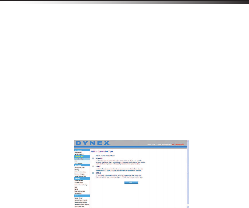
Using the Web-Based Advanced User Interface
The home page is the first page you will see when you access the Web-Based Advanced User
Interface (UI). The home page shows you a quick view of your router’s status and settings. All
advanced setup pages can be reached from this page.

18 Setting up your wireless router
Quick-Navigation links—You can go directly to any of your router’s UI pages by clicking
directly on these links. The links are divided into logical categories and grouped by tabs to
make finding a particular setting easier to find. Clicking the purple header of each tab will
show you a short description of the tab's function.
Home button—The Home button is available in every page of the UI. Pressing this button
will take you back to the home page.
Internet status indicator—This indicator is visible in all pages of the UI, indicating the
connection status of your router. When the indicator says Connection OK in green, your
router is connected to the Internet. When your router is not connected to the Internet, the
indicator will read No Connection in red. The indicator is automatically updated when you
make changes to the settings of your router.
Login/Logout button—This button lets you log in and out of your router with the press of
one button. When you are logged into your router, this button will change to read Logout.
Logging into your router will take you to a separate login page where you will need to enter a
password. When you are logged into your router, you can make changes to the settings.
When you are finished making changes, you can log out of your router by clicking the
Logout button.
Help button—The Help button gives you access to your router’s help pages.
LAN Settings—Shows you the settings of the Local Area Network (LAN) side of your router.
Changes can be made to the settings by clicking any one of the links (IP Address, Subnet
Mask, DHCP Server) or by clicking the LAN quick-navigation link on the left side of the
screen.
Features—Shows the status of your router’s NAT, firewall, and wireless features. Changes
can be made to the settings by clicking any one of the links or by clicking the
quick-navigation links on the left side of the screen.
Internet Settings—Shows the settings of the Internet/WAN side of your router that
connects to the Internet. Changes to any of these settings can be made by clicking the links
or by clicking the Internet/WAN quick-navigation link on the left side of the screen.
Version Info—Shows the firmware version, boot-code version, hardware version, and
serial number of your router.
Page Name—The page you are on can be identified by this name. This User Guide will
sometimes refer to pages by name. For instance LAN > LAN Settings refers to the LAN
Settings page.
Setting up your wireless router 19
Configure your router for connection to your Internet Service
Provider (ISP)
The Internet/WAN tab is where you will set up your router to connect to your Internet
Service Provider (ISP). Your router is capable of connecting to virtually any ISP’s system
provided you have correctly configured your router’s settings for your ISP’s connection type.
Your ISP connection settings are provided to you by your ISP.
To configure your router with the settings that your ISP gave you:
1Click Connection Type on the left side of the screen, then select the connection type
you use.
2If your ISP gave you DNS settings, click DNS to enter DNS address entries for ISPs that
require specific settings.
3Click MAC address to clone your computer's MAC address or type a specific WAN MAC
address, if required by your ISP.
When you have finished making settings, the Internet Status indicator will read
connection OK if your router is set up properly.
To set your Connection Type:
1Click Connection Type from the menu on the left side of the screen. The Connection
Type page opens. From this page, you can select the type of connection you use by
clicking the button next to your connection type and then clicking Next.
Setting your Internet Service Provider (ISP) connection type to dynamic IP
A dynamic connection type is the most common connection type used with cable modems.
Setting the connection type to dynamic in many cases is enough to complete the
connection to your ISP. Some dynamic connection types may require a host name. You can
enter your host name in the space provided if you were assigned one. Your host name is
assigned by your ISP. Some dynamic connections may require that you clone the MAC address
of the PC that was originally connected to the modem.
20 Setting up your wireless router
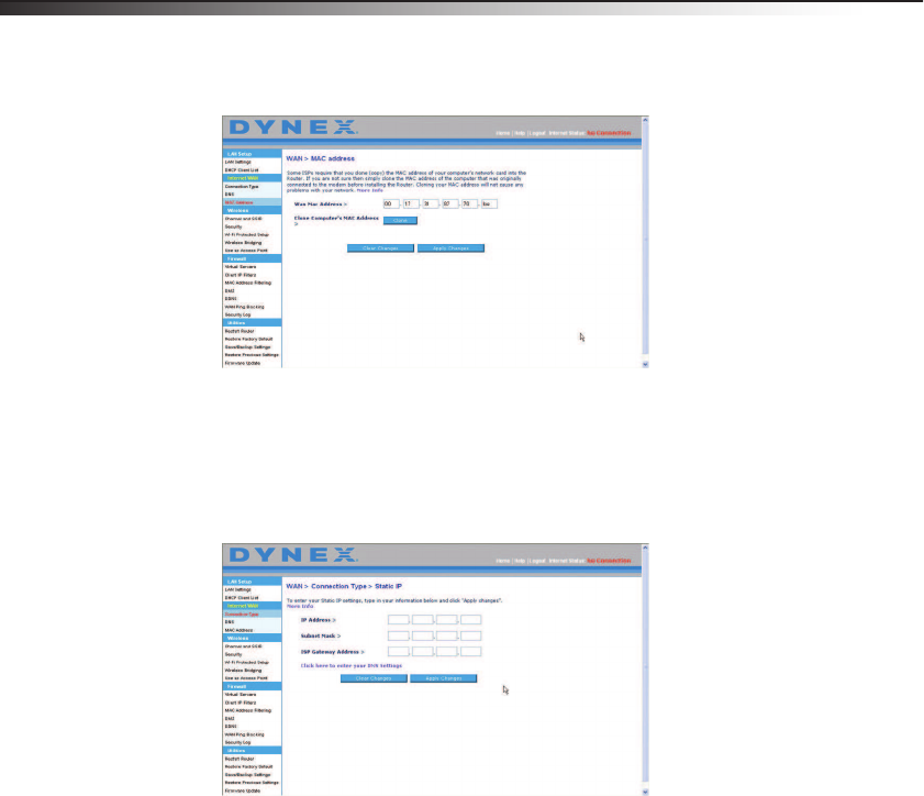
Change WAN MAC Address
If your ISP requires a specific MAC address to connect to the service, you can enter a specific
MAC address or clone the current computer's MAC address through this link.
Setting your Internet Service Provider (ISP) connection type to static IP
A static IP address connection type is less common than other connection types. If your ISP
uses static IP addressing, you will need your IP address, subnet mask, and ISP gateway
address. This information is available from your ISP or on the paperwork that your ISP left
with you. Type your information, then click Apply Changes. After you apply the changes,
the Internet Status indicator will read connection OK if your router is set up correctly.
Setting up your wireless router 21
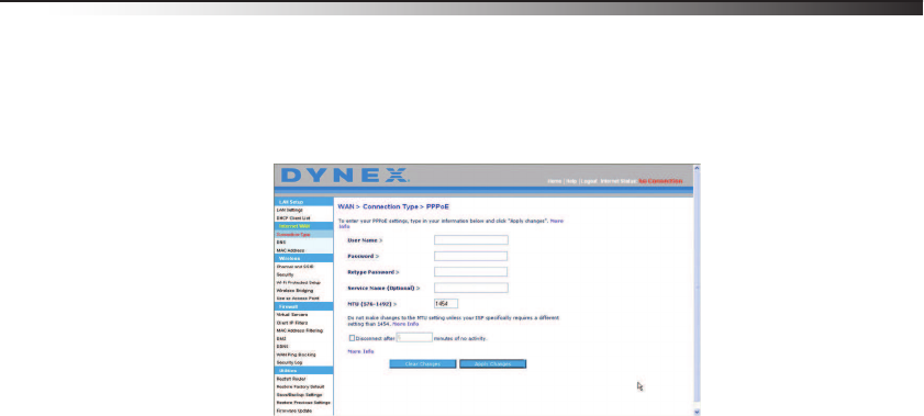
Setting your ISP connection type to PPPoE
Most DSL providers use PPPoE as the connection type. If you use a DSL modem to connect to
the Internet, your ISP may use PPPoE to log you into the service. If you have an Internet
connection in your home or small office that doesn't require a modem, you may also use
PPPoE.
Your connection type is PPPoE if:
• Your ISP gave you a user name and password, which is required to connect to the
Internet.
• Your ISP gave you software such as WinPOET or Enternet300 that you use to connect to
the Internet.
• You have to double-click a desktop icon other than your browser to get on the Internet.
Enter the following:
User Name–This space is provided to type your user name that was assigned by your ISP.
Password–Type your password and retype it into the Retype Password box to confirm it.
Service Name–A service name is rarely required by an ISP. If you are not sure if your ISP
requires a service name, leave this blank.
MTU–The MTU setting should never be changed unless your ISP gives you a specific MTU
setting. Making changes to the MTU setting can cause problems with your Internet
connection including disconnection from the Internet, slow Internet access, and problems
with Internet applications working properly.
Disconnect after X–The Disconnect feature is used to automatically disconnect your router
from your ISP when there is no activity for a specified period of time. For instance, placing a
check mark next to this option and entering 5 into the minute field will cause your router to
disconnect from the Internet after five minutes of no Internet activity. This option should be
used if you pay for your Internet service by the minute.
22 Setting up your wireless router
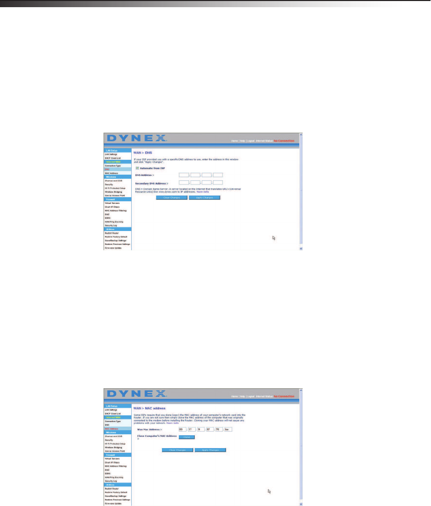
Setting custom Domain Name Server (DNS) settings
A Domain Name Server is a server located on the Internet that translates Universal Resource
Locators (URLs) like “www.dynex.com” into IP addresses. Many Internet Service Providers
(ISPs) do not require you to enter this information into your router. The Automatic from ISP
box should be checked if your ISP did not give you a specific DNS address. If you are using a
static IP connection type, then you may need to enter a specific DNS address and secondary
DNS address for your connection to work properly. If your connection type is dynamic or
PPPoE, it is likely that you do not have to enter a DNS address. Leave the Automatic from
ISP box checked. To enter the DNS address settings, uncheck the Automatic from ISP box
and enter your DNS entries in the spaces provided. Click Apply Changes to save the settings.
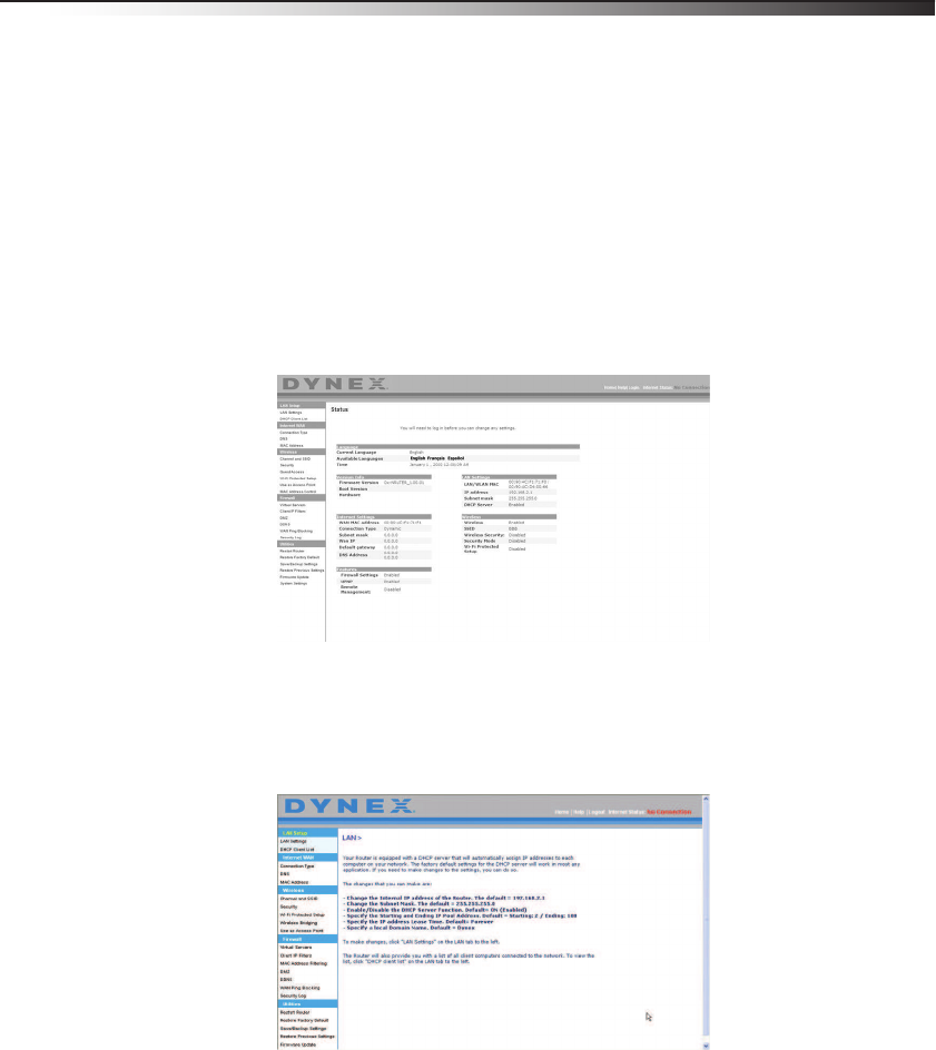
Configuring your WAN Media Access Controller (MAC) address
All network components including cards, adapters, and routers, have a unique serial number
called a MAC address. Your Internet Service Provider may record the MAC address of your
computer's adapter and only let that particular computer connect to the Internet service.
When you install your router, its own MAC address will be “seen” by the ISP and may cause
the connection not to work. Dynex has provided the ability to clone (copy) the MAC address
of the computer into your router. This MAC address, in turn, will be seen by the ISP’s system
as the original MAC address and will allow the connection to work. If you are not sure
whether your ISP needs to see the original MAC address, simply clone the MAC address of the
computer that was originally connected to the modem. Cloning the address will not cause
any problems with your network.
Setting up your wireless router 23
To clone your MAC Address:
1Make sure that you are using the computer that was ORIGINALLY CONNECTED to your
modem before your router was installed. Click
2Click Clone, then click Apply Changes. Your MAC address is now cloned to your
router.
To enter a specific MAC Address:
• Type a MAC address in the spaces provided, then click Apply Changes to save the
changes. Your router’s WAN MAC address is changed to the MAC address you specified.
Using the Web-Based Advanced User Interface
Using your Internet browser, you can access your router’s Web-Based Advanced User
Interface. Open your browser and enter 192.168.2.1 (do not type anything else such as
“http://” or “www”), then press Enter. Your router’s home page opens in your browser
window.
Viewing the LAN settings
Clicking the header of the LAN Setup will take you its header page. A quick description of
the functions can be found here. To view the settings or make changes to any of the LAN
settings, click LAN Settings, or to view the list of connected computers, click DHCP client
list.
24 Setting up your wireless router
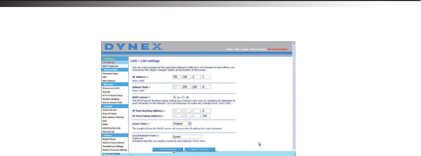
Changing LAN settings
All settings for the internal LAN setup of your router can be viewed and changed here.
IP Address–The IP address is the internal IP address of your router. The default IP
address is 192.168.2.1. To access the Web-Based Advanced User Interface, type this
IP address into the address bar of your browser. This address can be changed if needed.
To change the IP address, type the new IP address and click Apply Changes. The IP
address you choose should be a non-routable IP.
Examples of a non-routable IP are: 192.168.x.x (where x is anywhere between 0 and
255), and 10.x.x.x (where x is anything between 0 and 255).
Subnet Mask–There is no need to change the subnet mask. This is a unique,
advanced feature of your router. It is possible to change the subnet mask if necessary;
however, do NOT make changes to the subnet mask unless you have a specific reason
to do so. The default setting is 255.255.255.0.
DHCP Server–The DHCP server function makes setting up a network very easy by
assigning IP addresses to each computer on the network automatically. The default
setting is On. The DHCP server can be turned OFF if necessary; however, in order to do
so you must manually set a static IP address for each computer on your network. To
turn off the DHCP server, select Off, then click Apply Changes.
IP Pool–The range of IP addresses set aside for dynamic assignment to the computers
on your network. The default is 2-100 (99 computers). If you want to change this
number, you can do so by entering a new starting and ending IP address and clicking
Apply Changes. The DHCP server can assign 100 IP addresses automatically. This
means that you cannot specify an IP address pool larger than 100 computers. For
example, starting at 50 means you have to end at 150 or lower so as not to exceed the
100-client limit. The starting IP address must be lower in number than the ending IP
address.
Setting up your wireless router 25
Lease Time–The length of time the DHCP server will reserve the IP address for each
computer. We recommend that you leave the lease time set to Forever. The default
setting is Forever, meaning that any time a computer is assigned an IP address by the
DHCP server, the IP address will not change for that particular computer. Setting lease
times for shorter intervals such as one day or one hour frees IP addresses after the
specified period of time. This also means that a particular computer's IP address may
change over time. If you have set any of the other advanced features of your router
such as DMZ or client IP filters, these are dependent on the IP address. For this reason,
you will not want the IP address to change.
Local Domain Name–The default setting is Dynex. You can set a local domain name
(network name) for your network. There is no need to change this setting unless you
have a specific advanced need to do so. You can name the network anything you want
such as “MY NETWORK”.
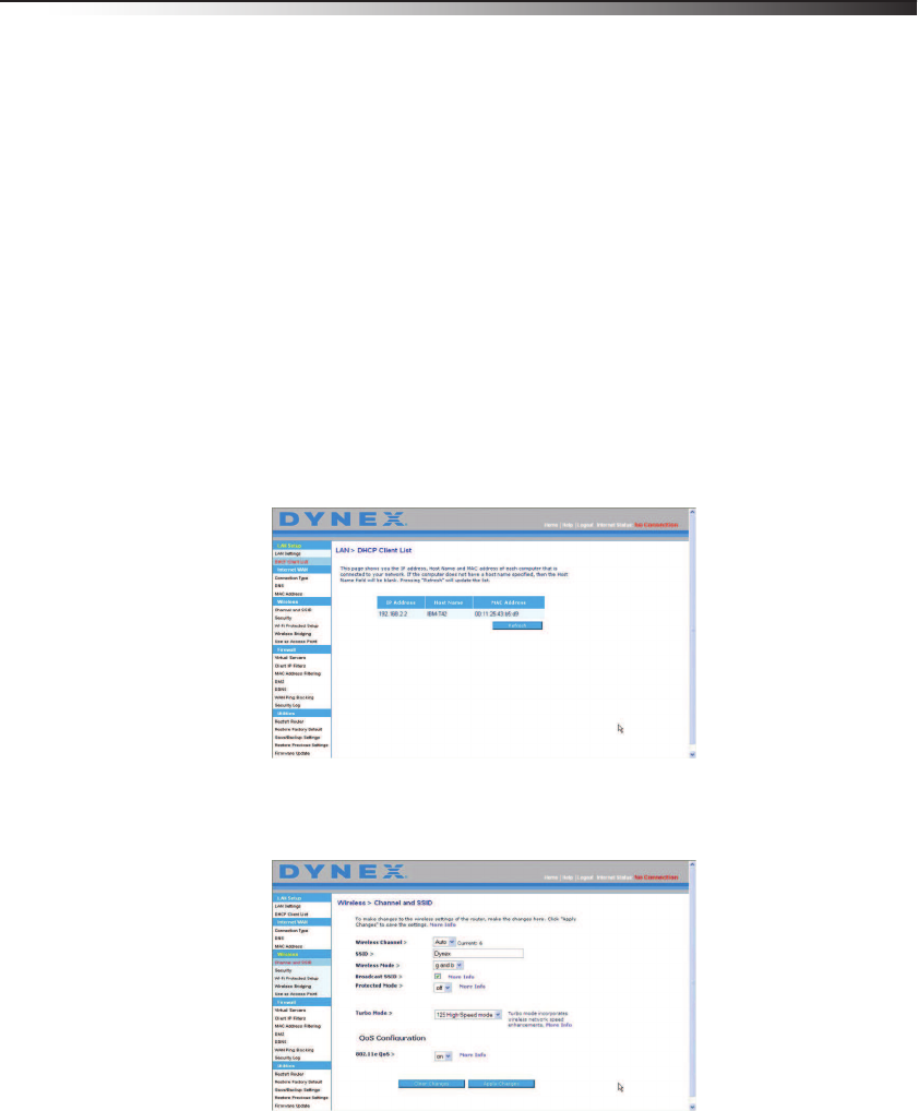
Viewing the DHCP Client List page
You can view a list of the computers (known as clients), which are connected to your
network. You are able to view the IP address of the computer, the host name (if the computer
has been assigned one), and the MAC address of the computer's network interface card (NIC).
Pressing the Refresh button will update the list. If there have been any changes, the list will
be updated.
Configuring the wireless network settings
Clicking the header of the Wireless tab will take you to the Wireless page. Under the
Wireless tab, there are links that let you make changes to the wireless network settings.

26 Setting up your wireless router
Changing the Wireless Channel
There are a number of operating channels from which you can choose. In the United States,
there are 11 channels. In Australia, the United Kingdom, and most of Europe, there are 13
channels. In a small number of other countries, there are other channel requirements. Your
router is configured to operate on the proper channels for the country in which you reside.
The channel can be changed, if needed. If there are other wireless networks operating in your
area, your network should be set to operate on a channel that is different than the other
wireless networks.
Extension channel
The IEEE 802.11n draft specification allows the use of a secondary channel to double the
bandwidth (see “Using the bandwidth switch” on page 27). An appropriate extension
channel will be displayed when operating in 40 MHz mode (see “Using the wireless mode
switch” on page 26). The channel can be changed, if needed.
Changing the wireless network name (SSID)
To identify your wireless network, a name (SSID for Service Set Identifier) is used. The SSID is
your network name. The default network name of your router is “Dynex” followed by six
digits that are unique to your router. You can change this to anything you choose, or you can
leave it unchanged. Keep in mind, if you decide to change your wireless network name, and
there are other wireless networks operating in your area, your network name needs to be
different from other wireless networks. To change the SSID, type the SSID that you want to
use in the SSID field and click Apply Changes. The change is immediate. If you make a
change to the SSID, your wireless-equipped computers may also need to be reconfigured to
connect to your new network name. Refer to the documentation of your wireless network
adapter for information on making this change.
Using the wireless mode switch
Your router can operate in three different wireless modes: 802.11n&802.11g&802.11b,
802.11g and 802.11b. The different modes are explained below.
802.11n&802.11g&802.11b
Setting your router to this mode will allow 802.11n, 802.11g, and 802.11n-compliant
devices to join the network. This is the factory default mode and ensures successful
operation with all Wi-Fi-compatible devices.
802.11g
802.11g mode works with 802.11g clients only. This mode is recommended only if you
want to prevent 802.11b clients from accessing your network. To switch modes, select
the desired mode from the Wireless Mode list, then click Apply Changes.
Off
This mode will turn OFF your router’s access point, so no wireless devices can join the
network. Turning off the wireless function of your router is a great way to secure your
network when you are away from home for a long period of time or don't want to use
the wireless feature of your router at a certain time.

Setting up your wireless router 27
Using the bandwidth switch
This switch let you set your router's wireless bandwidth modes. There are several modes
available:
20MHz only
Setting your router to this mode allows only 20 MHz operation. This mode is
compatible with N, draft 802.11n-, 802.11g-, and 802.11b-compliant devices, but will
limit N, draft 802.11n-compliant devices' bandwidth by half. Reducing bandwidth to
20 MHz-only operation might solve some wireless problems.
20MHz/40MHz auto
Setting your router to this mode lets it switch automatically between 20 MHz and
40 MHz operation. This mode enables 40 MHz operation, to maximize speed for N,
draft 802.11n-compliant devices when conditions permit. When a legacy 802.11g
access point is presented and occupies an adjacent secondary channel, your router
automatically reverts to 20 MHz operation to maximize compatibility. We recommend
using this as the default mode.
Using the Broadcast SSID feature
Note: This advanced feature should be employed by advanced users only.
For security, you can choose not to broadcast your network's SSID. Doing so will keep your
network name hidden from computers that are scanning for the presence of wireless
networks. To turn off the broadcast of the SSID, remove the check mark from the box next to
Broadcast SSID, then click Apply Changes. The change is immediate. Each computer now
needs to be set to connect to your specific SSID. An SSID of ANY will no longer be accepted.
Refer to the documentation of your wireless network adapter for information on making this
change.
Protected mode switch–Protected mode ensures proper operation of N, draft
802.11n-compliant devices on your wireless network when 802.11g or 802.11b devices are
present or when there is heavy 802.11g or 802.11b traffic in the operating environment. Use
protected mode if your network consists of a mix of Dynex N Wireless Cards and 802.11g or
802.11b cards on your network. If you are in an environment that includes little to no
802.11g or 802.11b wireless network traffic, you will achieve the best N wireless
performance with protected mode OFF. Conversely, in an environment with HEAVY 802.11g
or 802.11b traffic or interference, you will achieve the best N wireless performance with
protected mode ON. This will ensure N wireless performance is not affected.
Changing the Wireless Security Settings
Your router is equipped with the latest wireless security standard called Wi-Fi Protected
Access™2 (WPA2™) and the legacy security standard called Wired Equivalent Privacy (WEP).
Your router also supports the Wi-Fi Protected Setup (WPS), which simplifies the setup of a
wireless newtork. WPS uses familiar methodologies, such as typing in a Personal
Identification Number (PIN) or pushing a button, to let you automatically configure network
names and strong WPA™/WPA2 data encryption and authentication. To enable security, you
need to determine which standard you want to use. To access the security settings, click
Security on the Wireless tab.
28 Setting up your wireless router
Using Wi-Fi Protected Setup
WPS uses WPA2 for encryption. It does not provide additional security, but rather,
standardizes the method for securing your wireless network. You can use either the Push
Button Configuration (PBC) method or Personal Identification Number (PIN) method to let a
device access your wireless network.
PBC—Push and hold the WPS button located on the back of your router for three seconds.
Then, initiate the WPS procedure on the client device within two minutes. Refer to your
client's documentation on this procedure. Pushing the PBC button will automatically enable
WPS. The client has now been securely added to your wireless network.
PIN—The client device has a PIN number (either four or eight digits) that is associated with
WPS. Enable WPS through the screen illustrated below. Enter the client's PIN into your
router's internal registrar (accessed through this screen). The client will be automatically
enrolled into your wireless network within two minutes.
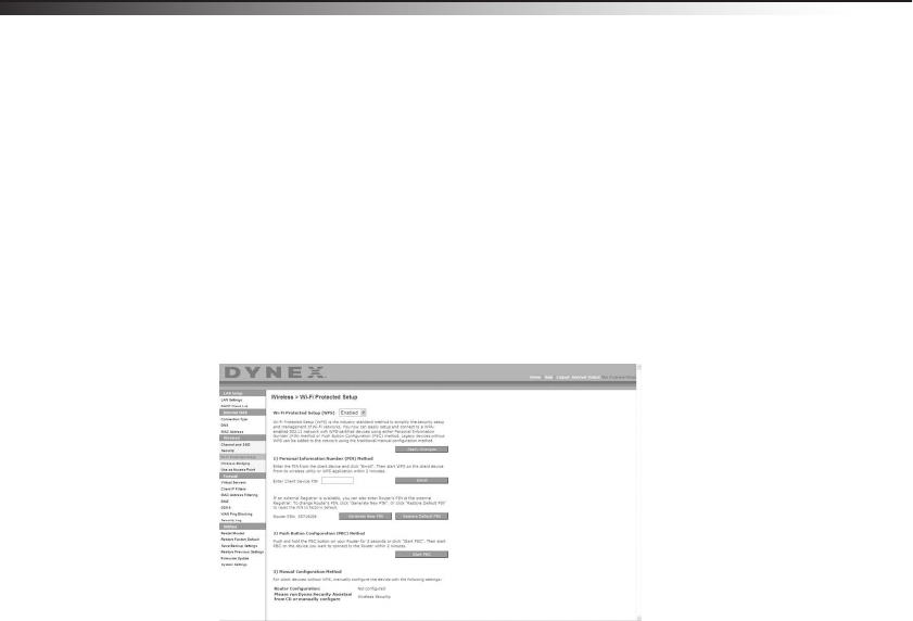
Wi-Fi Protected Setup (WPS)—Enabled or Disabled.
Personal Identification Number (PIN) Method—In this method, a wireless client
wanting to access your network must supply a 4- or 8-digit PIN to your router. After clicking
Enroll, you must start the WPS handshaking procedure from the client within two minutes.
Router PIN—If an external registrar is available, you can enter in your router’s PIN to the
registrar. Click Generate New PIN to change the PIN from the default value. Click Restore
Default PIN to reset the PIN value.
Push Button Configuration (PBC) Method—PBC is an alternate method to connect to a
WPS network. Push the PBC button located on the back of your router for three seconds,
then initiate the PBC on the client device. Alternatively, push the Start PBC soft button to
start this process.
Manual Configuration Method—This section lists the default security settings to be set
up if not using WPS.

Setting up your wireless router 29
WPA2 Requirements
IMPORTANT: In order to use WPA2 security, all your computers and wireless client adapters
must be upgraded with patches, driver, and client utility software that support WPA2. At
the time of this User Manual’s publication, a couple security patches are available, for free
download, from Microsoft®. These patches work only with the Windows XP operating
system. Other operating systems are not supported at this time.
For Windows XP computers that do not have Service Pack 2 (SP2), a file from Microsoft called
“Windows XP Support Patch for Wireless Protected Access (KB 826942)” is available for free
download at http://support.microsoft.com/kb/826942.
For Windows XP with Service Pack 2, Microsoft has released a free download to update the
wireless client components to support WPA2 (KB971021). The update is available from
http://support.microsoft.com/kb/917021.
Important: You also need to ensure that all your wireless client cards/adapters support
WPA2, and that you have downloaded and installed the latest driver. Most of the Dynex
wireless cards have driver updates available for download from the Dynex support site
atwww.dynexsupport.com.
Setting WPA/WPA2-Personal (PSK)
Like WPA security, WPA2 is available in both WPA2-Personal (PSK) mode and
WPA2-Enterprise (RADIUS) mode. Typically, WPA2-Personal (PSK) is the mode that will be
used in a home environment, while WPA2-Enterprise (RADIUS) is implemented in a business
environment where an external radius server distributes the network key to the clients
automatically. Your router supports WPA2-Personal (PSK).
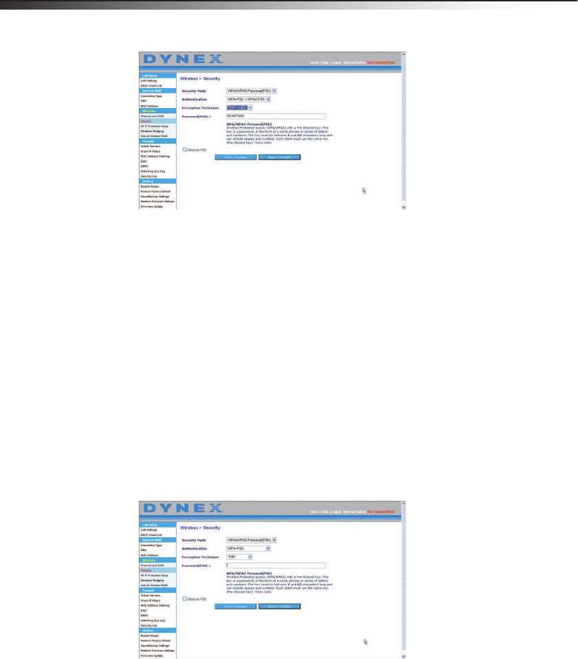
To set up WPA/WPA2:
1After you set up your router, click Security under the Wireless heading on the left
menu. The Wireless > Security page opens.
2Select WPA/WPA2-Personal (PSK) from the Security Mode list.
3For Authentication, select WPA-PSK, WPA2-PSK, or WPA-PSK + WPA2-PSK. This
setting must to be identical on the wireless clients that you set up. WPS-PSK +
WPA2-PSK mode lets your router support clients running either WPA or WPA2
security.
4For Encryption Technique, select TKIP, AES, or TKIP + AES. This setting must be
identical on the wireless clients that you set up.
5Enter your pre-shared key (PSK). This can be from eight to 63 characters and can be
letters, numbers, or symbols. This same key must be used on all of the clients that you
set up. For example, your PSK might be something like “Smith family network key.”
30 Setting up your wireless router
6Click Apply Changes to finish. You must now set all clients to match these settings
depending on the type of access you want them to have.
Important: Make sure that your wireless computers are updated to work with WPA2 and
have the correct settings to get proper connection to your router.
Setting WPA Security
Note: To use WPA security, your wireless network cards must be equipped with software that
supports WPA. At the time this User Manual was published, a security patch from
Microsoft is available for free download. This patch works only with Windows XP.
Your router supports WPA-Personal (PSK), which uses a pre-shared key (PSK) as the security
key. A pre-shared key is basically a password that is between eight and 63 characters long. It
can be a combination of letters, numbers, or characters. Each client uses the same key to
access the network. Typically this is the mode that will be used in a home environment.
To set WPA-PSK security:
1From the Security Mode drop-down menu, select WPA/WPA-Personal (PSK).
2For Encryption Technique, select TKIP or AES. This setting will have to be identical
on the clients that you set up.
3Enter your pre-shared key. This can be from eight to 63 characters and can be letters,
numbers, or symbols. This same key must be used on all of the clients that you set up.
4Click Apply Changes to finish. You must now set all clients to match these settings.
Setting up your wireless router 31
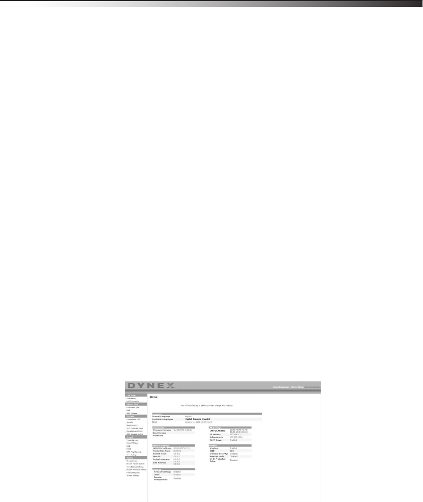
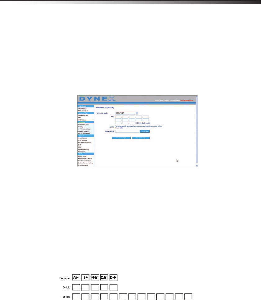
Setting WEP encryption
Note to Mac users: The Passphrase option will not operate with Apple® AirPort®. To
configure encryption for your Mac computer, set the encryption using the manual method
described in the next section.
To set WEP encryption:
1From the Security Mode drop-down menu, select 128-bit WEP or 64-bit WEP from
the.
2After selecting your WEP encryption mode, enter you WEP key manually by typing the
hex WEP key, or type a passphrase in the PassPhrase field, then click Generate to
create a WEP key from the passphrase.
3Click Apply Changes to finish. You must now set all of your clients to match these
settings.
Encryption in your router is now set. Each of your computers on your wireless network
will now need to be configured with the same passphrase. Refer to the documentation
of your wireless network adapter for information on making this change.
Using a Hexadecimal Key
A hexadecimal key is a mixture of numbers and letters from A-F and 0-9. 64-bit keys are 10
digits long and can be divided into five two-digit numbers. 128-bit keys are 26 digits long
and can be divided into 13 two-digit numbers.
For instance:
AF 0F 4B C3 D4 = 64-bit key
C3 03 0F AF 0F 4B B2 C3 D4 4B C3 D4 E7 = 128-bit key
In the table below, make up your key by writing in two characters between A-F and 0-9. You
will use this key to program the encryption settings on your router and your wireless
computers.
Note to Mac users: Original Apple AirPort products support 64-bit encryption only. Apple
AirPort 2 products can support 64-bit or 128-bit encryption. Check your product to see
which version you are using. If you cannot configure your network with 128-bit
encryption, try 64-bit encryption.
32 Setting up your wireless router
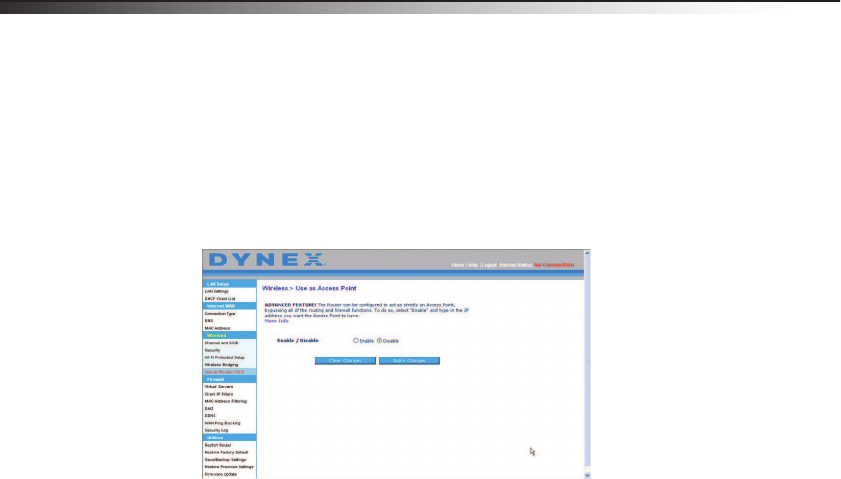
Using the Access Point mode
Note: This advanced feature should be employed by advanced users only. Your router can be
configured to work as a wireless network access point. Using this mode will defeat the
NAT IP sharing feature and DHCP server. In Access Point (AP) mode, your router will need
to be configured with an IP address that is in the same subnet as the rest of the network
that you will bridge to. The default IP address is 192.168.2.254 and subnet mask is
255.255.255.0. These can be customized for your needs.
To use the Access Point mode:
1Click Use as access point under the Wireless heading on the left menu. The Wireless
> Use as Access Point page opens.
2Select Enable. When you select this option, you will be able to change the IP settings.
3Set your IP settings to match your network, then click Apply Changes.
4Connect a cable from the Modem port on your router to your existing network.
Your router is now acting as an access point. To access your router’s Web-Based
Advanced User Interface again, type the IP address you specified into your browser's
navigation bar. You can set the encryption settings, MAC address filtering, SSID, and
channel normally.
Setting up your wireless router 33
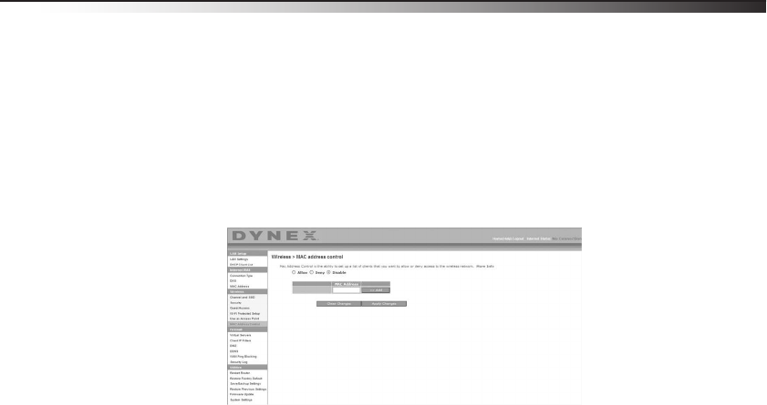
Setting MAC Address Control
The MAC address filter is a powerful security feature that lets you specify which computers
are allowed on the wireless network.
Note: This list applies only to wireless computers.
This list can be configured so any computer attempting to access the wireless network that is
not specified in the filter list will be denied access. When you enable this feature, you must
enter the MAC address of each client (computer) to which you want to allow network access.
The Block feature lets you turn on and off access to the network easily for any computer
without having to add and remove the computer's MAC address from the list.
Setting up an Allow Access list
To set up an Allow Access list:
1Click the Allow radio button to begin setting up a list of computers allowed to connect
to the wireless network.
2In the MAC Address field that is blank, type the MAC address of the wireless computer
you want to be able to access the wireless network, then click <<Add.
3Repeat Step 2 until all of the computers you want to add have been entered.
4Click Apply Changes to finish.
Setting up a Deny Access list
The Deny Access list lets you specify computers that you DO NOT want to access the network.
Any computer in the list will not be allowed access to the wireless network. All others will.
To set up a Deny Access list:
1Click the Deny radio button to begin setting up a list of computers to be denied access
to the wireless network.
2In the MAC Address field that is blank, type the MAC address of the wireless computer
you want to deny access to the wireless network, then click <<Add.
3Repeat Step 2 until all of the computers you want to deny access to have been entered.
4Click Apply Changes to finish.
34 Setting up your wireless router
Configuring the firewall
Your router is equipped with a firewall that will protect your network from a wide array of
common hacker attacks including:
• IP Spoofing
• Land Attack Ping of Death (PoD)
• Denial of Service (DoS)
• IP with zero length
• Smurf Attack
• TCP Null Scan
• SYN flood
• UDP flooding
• Tear Drop Attack
• ICMP defect
• RIP defect
• Fragment flooding
The firewall also masks common ports that are frequently used to attack networks. These
ports appear to be stealth, meaning that for all intents and purposes, they do not exist to a
would-be hacker. You can turn the firewall function off if needed, however, it is
recommended that you leave the firewall enabled. Disabling the firewall protection will not
leave your network completely vulnerable to hacker attacks, but it is recommended that you
leave the firewall enabled.
Setting up your wireless router 35
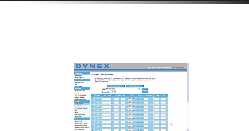
Configuring Internal Forwarding settings
The Virtual Servers function lets you route external (Internet) calls for services such as a Web
server (port 80), FTP server (Port 21), or other applications through your router to your
internal network. Since your internal computers are protected by a firewall, computers
outside your network (over the Internet) cannot get to them because they cannot be seen. A
list of common applications has been provided in case you need to configure the Virtual
Server function for a specific application. If your application is not listed, you will need to
contact the application vendor to find out which port settings you need.
To enter settings into the virtual server:
1Open the Virtual Servers page, then enter the IP address in the space provided for the
internal (server) machine, and the port(s) required to pass.
2Select the port type (TCP or UDP), check the Enable box, then click Apply Changes.
Each inbound port entry has two fields with five characters maximum per field that
allows a start and end port range, for example [xxxxx]-[xxxxx]. For each entry, you
can enter a single port value by filling in the two fields with the same value (for
example, [7500]-[7500]) or a wide range of ports (for example [7500]-[9000]). If
you need multiple single port values or a combination of ranges and a single value,
you must use multiple entries up to the maximum of 20 entries (for example,
1. [7500]-[7500], 2. [8023]-[8023], 3. [9000]-[9000]). You can only pass one port
per internal IP address. Opening ports in your firewall can pose a security risk. You can
enable and disable settings quickly. It is recommended that you disable the settings
when you are not using a specific application.
2006/8/16 v1.0
Federal Communication Commission Interference Statement
This equipment has been tested and found to comply with the limits for a Class B digital
device, pursuant to Part 15 of the FCC Rules. These limits are designed to provide
reasonable protection against harmful interference in a residential installation. This
equipment generates, uses and can radiate radio frequency energy and, if not installed
and used in accordance with the instructions, may cause harmful interference to radio
communications. However, there is no guarantee that interference will not occur in a
particular installation. If this equipment does cause harmful interference to radio or
television reception, which can be determined by turning the equipment off and on, the
user is encouraged to try to correct the interference by one of the following measures:
- Reorient or relocate the receiving antenna.
- Increase the separation between the equipment and receiver.
- Connect the equipment into an outlet on a circuit different from that
to which the receiver is connected.
- Consult the dealer or an experienced radio/TV technician for help.
FCC Caution: Any changes or modifications not expressly approved by the party
responsible for compliance could void the user's authority to operate this equipment.
This device complies with Part 15 of the FCC Rules. Operation is subject to the following
two conditions: (1) This device may not cause harmful interference, and (2) this device
must accept any interference received, including interference that may cause undesired
operation.
IMPORTANT NOTE:
FCC Radiation Exposure Statement:
This equipment complies with FCC radiation exposure limits set forth for an uncontrolled
environment. This equipment should be installed and operated with minimum distance
20cm between the radiator & your body.
This transmitter must not be co-located or operating in conjunction with any other
antenna or transmitter.
The availability of some specific channels and/or operational frequency bands are
country dependent and are firmware programmed at the factory to match the intended
destination. The firmware setting is not accessible by the end user.
2006/8/16 v1.0
Industry Canada statement:
This device complies with RSS-210 of the Industry Canada Rules. Operation is subject to
the following two conditions:
(1) This device may not cause harmful interference, and (2) this device must accept any
interference received, including interference that may cause undesired operation.
IMPORTANT NOTE:
Radiation Exposure Statement:
This equipment complies with IC radiation exposure limits set forth for an uncontrolled
environment. This equipment should be installed and operated with minimum distance
20cm between the radiator & your body.
This device has been designed to operate with an antenna having a maximum gain of 2
dB. Antenna having a higher gain is strictly prohibited per regulations of Industry Canada.
The required antenna impedance is 50 ohms.