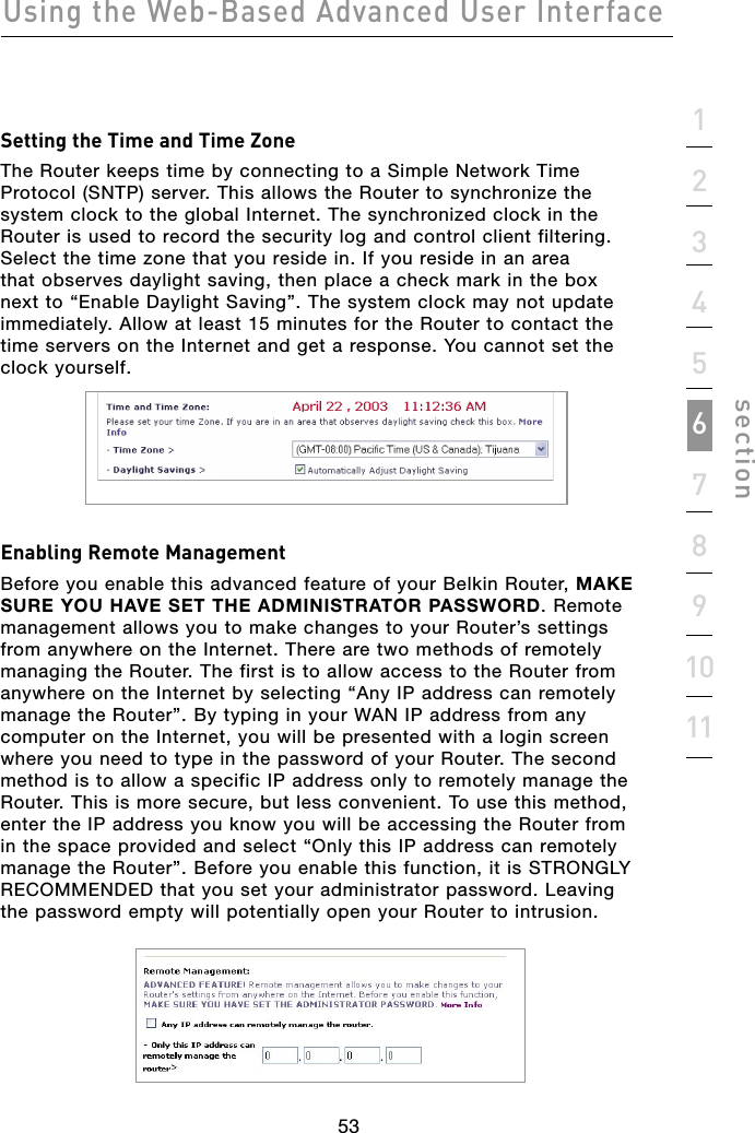
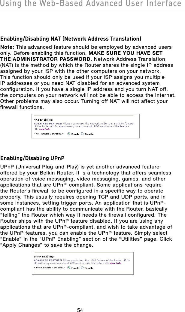
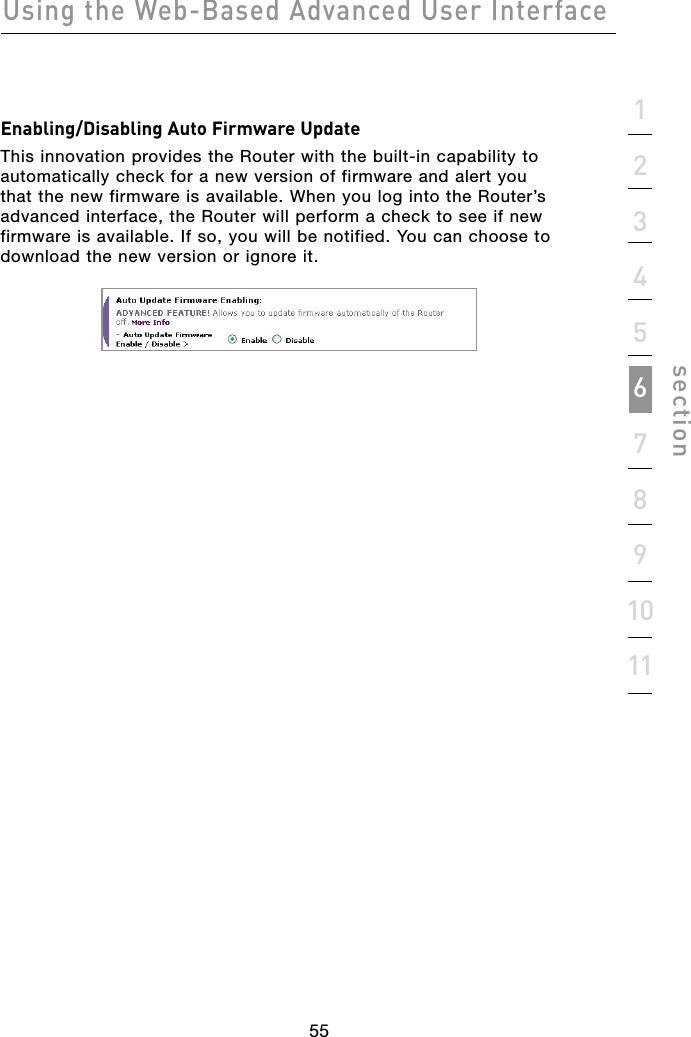
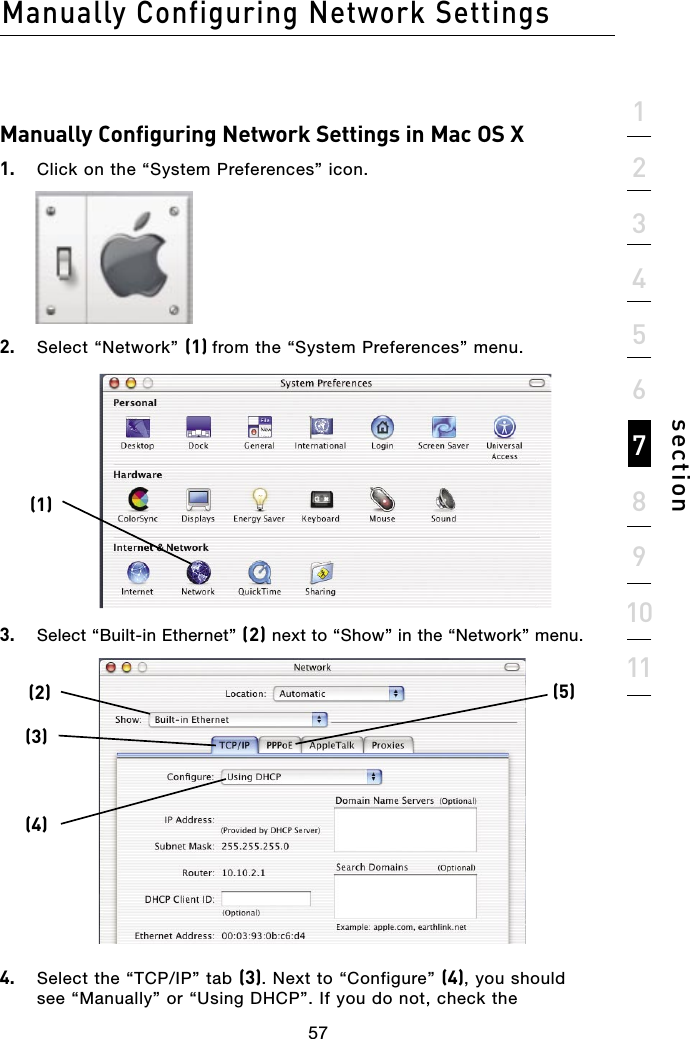
Belkin F5D52314 4+1 PORT WIRED GATEWAY ROUTER User Manual P74753 F5D5231 4 v2000 man indd
Belkin International, Inc. 4+1 PORT WIRED GATEWAY ROUTER P74753 F5D5231 4 v2000 man indd
Belkin >
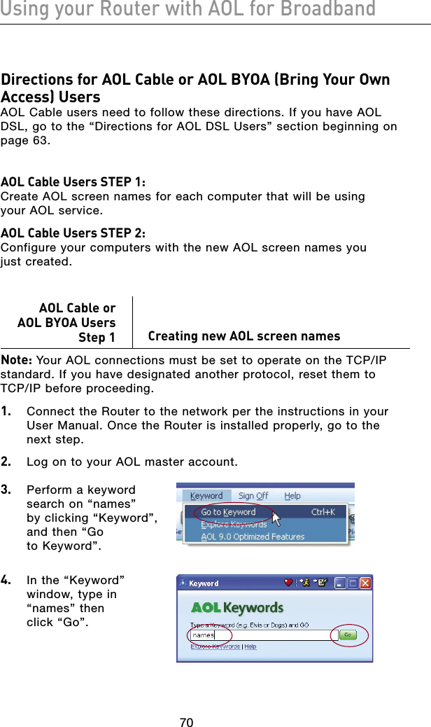
Contents
- 1. USERS MANUAL 1 OF 2
- 2. USER MANUAL 2 OF 2
USER MANUAL 2 OF 2
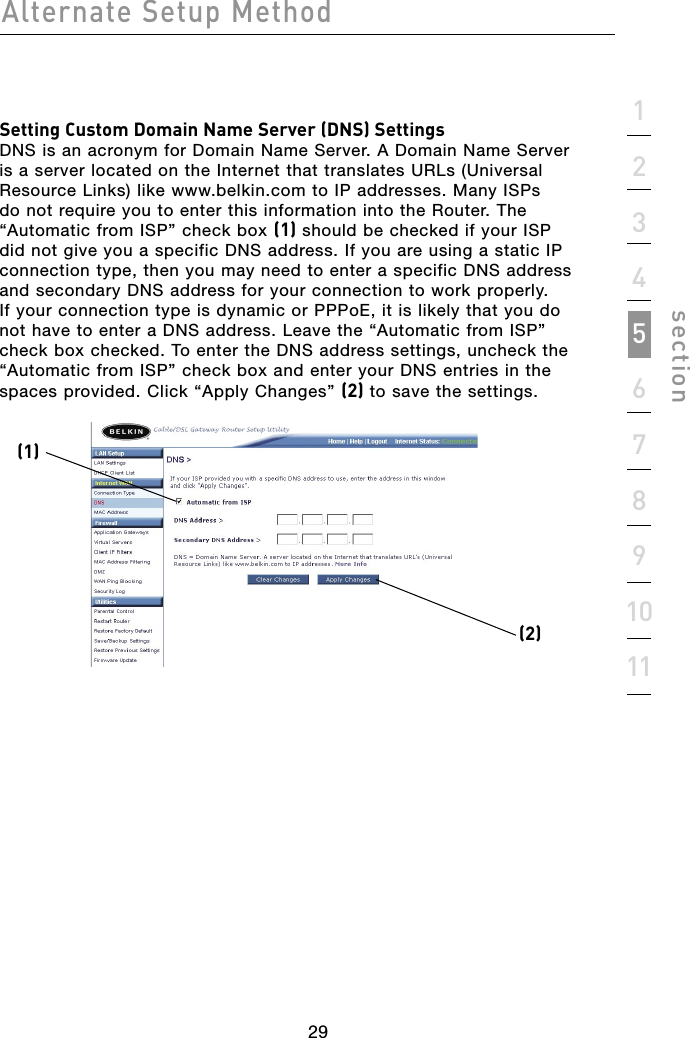
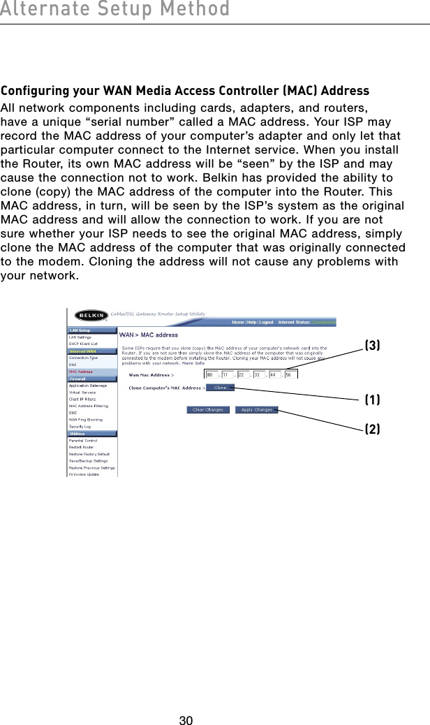
![2928Alternate Setup Method2928Alternate Setup MethodSetting your Connection Type if you are a Telstra® BigPond User[Australia Only] Your user name and password are provided to you by Telstra BigPond. Enter this information below. Choosing your state from the drop-down menu (6) will automatically fill in your login server IP address. If your login server address is different than the one provided here, you may manually enter the login server IP address by placing a check in the box next to “User decide login server manually” (4) and type in the address next to “Login Server” (5). When you have entered all of your information, click “Apply Changes” (7). After you apply the changes, the “Internet Status” indicator will read “connection OK” if your Router is set up properly.(1) Select your StateSelect your state from the drop-down menu (6). The “Login Server” box will automatically be filled in with an IP address. If for some reason this address does not match the address that Telstra has given you, you can manually enter the login server address. See “User decide login server manually” (4). (2) User NameProvided by your ISP. Type in your user name here. (3) PasswordType in your password and retype it into the “Retype Password” box to confirm it.(4) User decide login server manuallyIf your login server IP address is not available in the “Select Your State” drop-down menu (6), you may manually enter the login server IP address by placing a check in the box next to “User decide login server manually” and type in the address next to “Login Server” (5).(1)(7)(2)(3)(4)(5)(6)](https://usermanual.wiki/Belkin/F5D52314.USER-MANUAL-2-OF-2/User-Guide-567173-Page-1.png)