Belkin F5D52314 4+1 PORT WIRED GATEWAY ROUTER User Manual P74753 F5D5231 4 v2000 man indd
Belkin International, Inc. 4+1 PORT WIRED GATEWAY ROUTER P74753 F5D5231 4 v2000 man indd
Belkin >
Contents
- 1. USERS MANUAL 1 OF 2
- 2. USER MANUAL 2 OF 2
USER MANUAL 2 OF 2
2928
Alternate Setup Method
2928
Alternate Setup Method
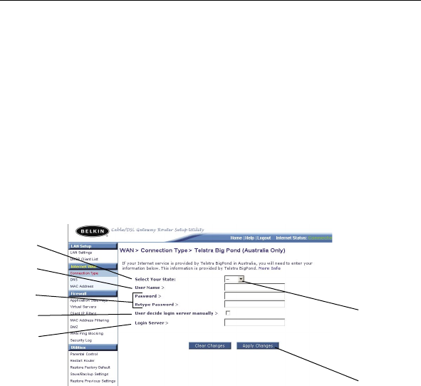
Setting your Connection Type if you are a Telstra® BigPond User
[Australia Only] Your user name and password are provided to you
by Telstra BigPond. Enter this information below. Choosing your state
from the drop-down menu (6) will automatically fill in your login server
IP address. If your login server address is different than the one
provided here, you may manually enter the login server IP address by
placing a check in the box next to “User decide login server manually”
(4) and type in the address next to “Login Server” (5). When you
have entered all of your information, click “Apply Changes” (7).
After you apply the changes, the “Internet Status” indicator will read
“connection OK” if your Router is set up properly.
(1) Select your State
Select your state from the drop-down menu (6). The “Login Server”
box will automatically be filled in with an IP address. If for some
reason this address does not match the address that Telstra has
given you, you can manually enter the login server address. See “User
decide login server manually” (4).
(2) User Name
Provided by your ISP. Type in your user name here.
(3) Password
Type in your password and retype it into the “Retype Password” box
to confirm it.
(4) User decide login server manually
If your login server IP address is not available in the “Select Your
State” drop-down menu (6), you may manually enter the login server
IP address by placing a check in the box next to “User decide login
server manually” and type in the address next to “Login Server” (5).
(1)
(7)
(2)
(3)
(4)
(5)
(6)
29
Alternate Setup Method
29
section
1
2
3
4
5
6
7
8
9
10
11
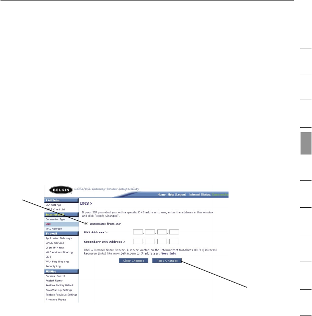
Setting Custom Domain Name Server (DNS) Settings
DNS is an acronym for Domain Name Server. A Domain Name Server
is a server located on the Internet that translates URLs (Universal
Resource Links) like www.belkin.com to IP addresses. Many ISPs
do not require you to enter this information into the Router. The
“Automatic from ISP” check box (1) should be checked if your ISP
did not give you a specific DNS address. If you are using a static IP
connection type, then you may need to enter a specific DNS address
and secondary DNS address for your connection to work properly.
If your connection type is dynamic or PPPoE, it is likely that you do
not have to enter a DNS address. Leave the “Automatic from ISP”
check box checked. To enter the DNS address settings, uncheck the
“Automatic from ISP” check box and enter your DNS entries in the
spaces provided. Click “Apply Changes” (2) to save the settings.
(1)
(2)
3130
Alternate Setup Method
3130
Alternate Setup Method
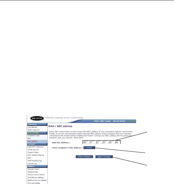
Configuring your WAN Media Access Controller (MAC) Address
All network components including cards, adapters, and routers,
have a unique “serial number” called a MAC address. Your ISP may
record the MAC address of your computer’s adapter and only let that
particular computer connect to the Internet service. When you install
the Router, its own MAC address will be “seen” by the ISP and may
cause the connection not to work. Belkin has provided the ability to
clone (copy) the MAC address of the computer into the Router. This
MAC address, in turn, will be seen by the ISP’s system as the original
MAC address and will allow the connection to work. If you are not
sure whether your ISP needs to see the original MAC address, simply
clone the MAC address of the computer that was originally connected
to the modem. Cloning the address will not cause any problems with
your network.
(1)
(2)
(3)

31
Alternate Setup Method
31
section
1
2
3
4
5
6
7
8
9
10
11
Cloning your MAC Address
To clone your MAC address, make sure that you are using the
computer that was ORIGINALLY CONNECTED to your modem before
the Router was installed. Click the “Clone” button (1). Click “Apply
Changes” (2). Your MAC address is now cloned to the Router.
Entering a Specific MAC Address
In certain circumstances you may need a specific WAN MAC address.
You can manually enter one in the “MAC Address” page. Type in a
MAC address in the spaces provided (3) and click “Apply Changes”
(2) to save the changes. The Router’s WAN MAC address will now be
changed to the MAC address you specified.
3332
Using the Web-Based Advanced User Interface
3332
Using the Web-Based Advanced User Interface
Using your Internet browser, you can access the Router’s Web-Based
Advanced User Interface. In your browser, type “192.168.2.1” (do
not type in anything else such as “http://” or “www”) then press the
“Enter” key.
You will see the Router’s home page in your browser window.
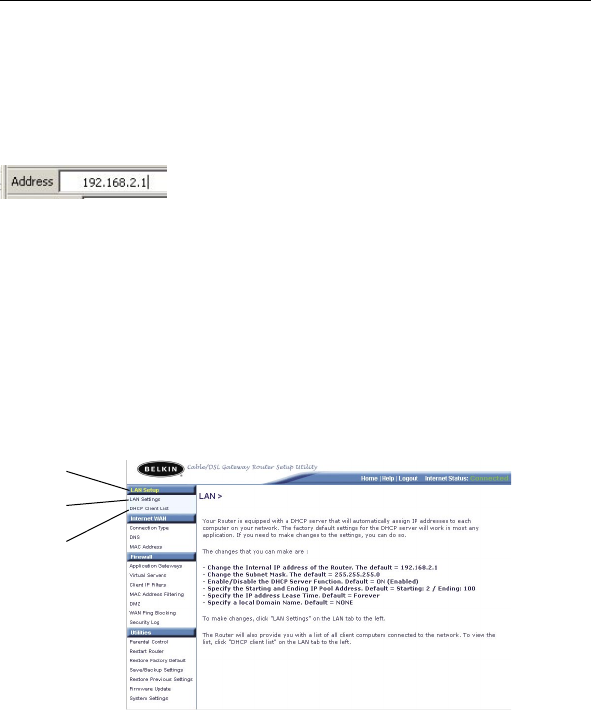
LAN Setup
Clicking on the header of the LAN tab (1) will take you to the LAN
tab’s header page. A quick description of the functions can be
found here. To view the settings or make changes to any of the LAN
settings, click on “LAN Settings” (2) or to view the list of connected
computers, click on “DHCP Client List” (3).
(1)
(2)
(3)
33
Using the Web-Based Advanced User Interface
33
section
1
2
3
4
5
6
7
8
9
10
11
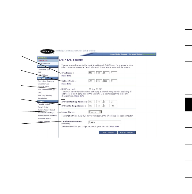
Changing LAN Settings
All settings for the internal LAN setup of the Router can be viewed
and changed here.
(1) IP Address
The “IP address” is the internal IP address of the Router. The default
IP address is “192.168.2.1”. To access the advanced setup interface,
type this IP address into the address bar of your browser. This
address can be changed if needed. To change the IP address, type in
the new IP address and click “Apply Changes”. The IP address you
choose should be a non-routable IP. Examples of a non-routable
IP are:
192.168.x.x (where x is anything between 0 and 255)
10.x.x.x (where x is anything between 0 and 255)
(2) Subnet Mask
ADVANCED FEATURE! There is no need to change the subnet mask.
It is possible to change the subnet mask if necessary. Only make
changes to the subnet mask if you specifically have a reason to do
so. The default setting is “255.255.255.0”.
(3) DHCP Server
The DHCP server function makes setting up a network very easy
by assigning IP addresses to each computer on the network
automatically. The default setting is “ON”. The DHCP server can be
turned OFF if necessary. Turning off the DHCP server will require you
to manually set a static IP address for each computer on your network.
To turn off the DHCP server, select “Off” and click “Apply Changes”.
(1)
(2)
(3)
(4)
(5)
(6)

3534
Using the Web-Based Advanced User Interface
3534
Using the Web-Based Advanced User Interface
(4) IP Pool
The range of IP addresses set aside for dynamic assignment to the
computers on your network. The default is 2–100 (99 computers). If
you want to change this number, you can by entering a new starting
and ending IP address and clicking on “Apply Changes”. The DHCP
server can assign 100 IP addresses automatically. This means that
you cannot specify an IP address pool larger than 100 computers. For
instance, starting at 50 means you have to end at 150 or lower so as
not to exceed the 100-client limit. The starting IP address must be
lower in number than the ending IP address.
(5) Lease Time
The length of time the DHCP server will reserve the IP address for
each computer. The default setting is forever, meaning that any time
a computer is assigned an IP address by the DHCP server, the IP
address will not change for that particular computer. Setting lease
times for shorter intervals such as one day or one hour frees IP
addresses after the specified period of time. This also means that a
particular computer’s IP address may change over time. If you have
set any of the other advanced features of the Router such as DMZ or
client IP filters, these are dependent on the IP address. You will not
want these to change. We recommend for this reason that you leave
the lease time set to “Forever”.
(6) Local Domain Name
You can set a local domain name (network name) for your network.
There is no need to change this setting unless you have a specific
advanced need to do so. You can name the network anything you
want such as “MY NETWORK”. The default setting is “Belkin”.
35
Using the Web-Based Advanced User Interface
35
1
2
3
4
5
6
7
8
9
10
11
section
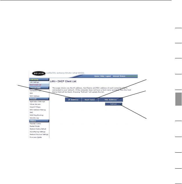
Viewing the DHCP Client List Page
You can view a list of the computers (known as clients), which are
connected to your network. You are able to view the IP address (1) of
the computer, the host name (2) (if the computer has been assigned
one), and the MAC address (3) of the computer’s network interface
card (NIC). Pressing the “Refresh” (4) button will update the list. If
there have been any changes, the list will be updated.
(2)
(3)
(1)
(4)

3736
Using the Web-Based Advanced User Interface
3736
Using the Web-Based Advanced User Interface
Configuring the Firewall
Your Router is equipped with a firewall that will protect your network
from a wide array of common hacker attacks including:
• IP Spoofing
• Land Attack
• Ping of Death (PoD)
• Denial of Service (DoS)
• IP with zero length
• Smurf Attack
• TCP Null Scan
• SYN flood
• UDP flooding
• Tear Drop Attack
• ICMP defect
• RIP defect
• Fragment flooding
The firewall also masks common ports that are frequently used to
attack networks. These ports appear to be “Stealth” meaning that for
all intents and purposes, they do not exist to a would-be hacker. You
can turn the firewall function off if needed; however, it is recommended
that you leave the firewall enabled. Disabling the firewall protection will
not leave your network completely vulnerable to hacker attacks, but it
is recommended that you leave the firewall enabled.
37
Using the Web-Based Advanced User Interface
37
1
2
3
4
5
6
7
8
9
10
11
section
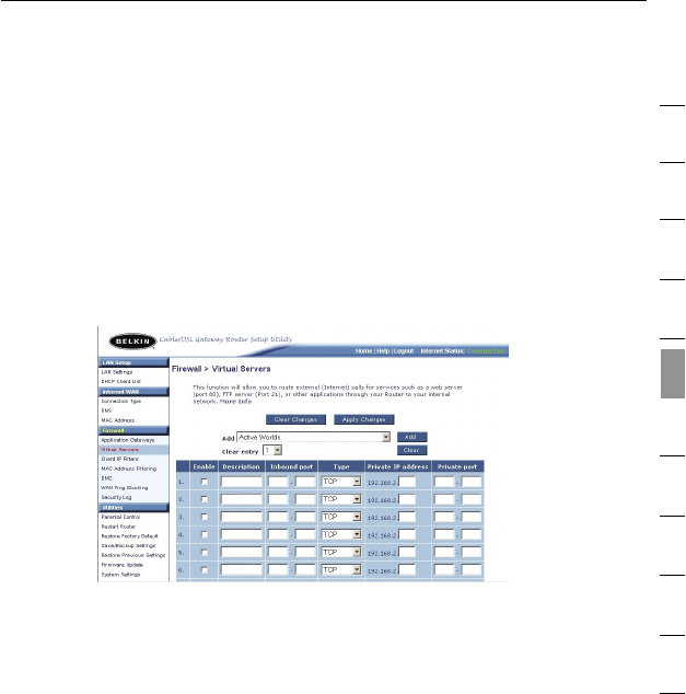
Configuring Virtual Servers
The “Virtual Servers” function will allow you to route external (Internet)
calls for services such as a web server (port 80), FTP server (Port 21),
or other applications through your Router to your internal network.
Since your internal computers are protected by a firewall, machines
from the Internet cannot get to them because they cannot be “seen”.
If you need to configure the “Virtual Servers” function for a specific
application, a list of common applications has been provided. If your
application is not listed, you will need to contact the application
vendor to find out which port settings you need.
Choosing an Application
Select your application from the drop-down list. Click “Add”. The
settings will be transferred to the next available space in the screen.
Click “Apply Changes” to save the setting for that application. To
remove an application, select the number of the row that you want to
remove, then click “Clear”.
Manually Entering Settings into the Virtual Server
To manually enter settings, enter the IP address in the space provided
for the internal (server) machine and the port(s) required to pass (use
a comma between multiple ports). Then select the port type (TCP
or UDP) and click “Apply Changes”. You can only pass one port
per internal IP address. Opening ports in your firewall can pose a
security risk. You can enable and disable settings very quickly. It is
recommended that you disable the settings when you are not using a
specific application.
3938
Using the Web-Based Advanced User Interface
3938
Using the Web-Based Advanced User Interface
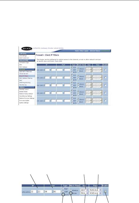
Setting Client IP Filters
The Router can be configured to restrict access to the Internet,
email, or other network services at specific days and times.
Restriction can be set for a single computer, a range of computers,
or multiple computers.
To restrict Internet access to a single computer for example, enter
the IP address of the computer you wish to restrict access to in
the IP fields (1). Next, enter “80” and “80” in the “Port” fields (2).
Select “Both” (3). Select “Block” (4). You can also select “Always”
to block access all of the time. Select the day to start on top (5),
the time to start on top (6), the day to end on the bottom (7), and
the time to stop (8) on the bottom. Select “Enable” (9). Click “Apply
Changes”. The computer at the IP address you specified will now be
blocked from Internet access at the times you specified. Note: Be
sure you have selected the correct time zone under “Utilities> System
Settings> Time Zone”.
(3) (4) (7) (8) (9)
(1) (2) (5) (6)
39
Using the Web-Based Advanced User Interface
39
1
2
3
4
5
6
7
8
9
10
11
section
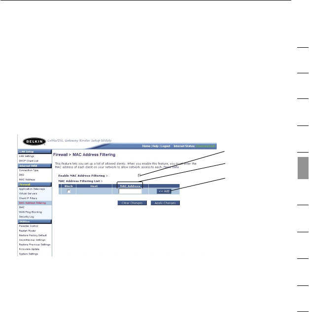
Setting MAC Address Filtering
The MAC address filter is a powerful security feature that allows
you to specify which computers are allowed on the network. Any
computer attempting to access the network that is not specified in
the filter list will be denied access. When you enable this feature, you
must enter the MAC address of each client on your network to allow
network access to each. The “Block” feature lets you turn on and off
access to the network easily for any computer without having to add
and remove the computer’s MAC address from the list.
To enable this feature, select “Enable MAC Address Filtering” (1).
Next, enter the MAC address of each computer on your network by
clicking in the space provided (2) and entering the MAC address of
the computer you want to add to the list. Click “Add” (3), then “Apply
Changes” to save the settings. To delete a MAC address from the list,
simply click “Delete” next to the MAC address you wish to delete.
Click “Apply Changes” to save the settings.
Note: You will not be able to delete the MAC address of the computer
you are using to access the Router’s administrative functions (the
computer you are using now).
(1)
(2)
(3)
4140
Using the Web-Based Advanced User Interface
4140
Using the Web-Based Advanced User Interface
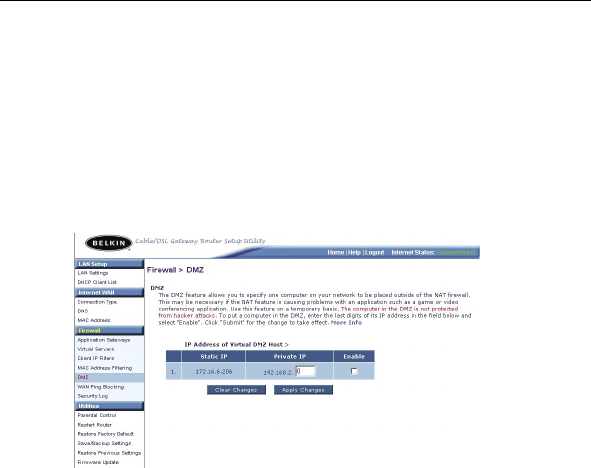
Enabling the Demilitarized Zone (DMZ)
The DMZ feature allows you to specify one computer on your network
to be placed outside of the firewall. This may be necessary if the
firewall is causing problems with an application such as a game or
video conferencing application. Use this feature on a temporary basis.
The computer in the DMZ is NOT protected from hacker attacks.
To put a computer in the DMZ, enter the last digits of its IP address in
the IP field and select “Enable”. Click “Apply Changes” for the change
to take effect. If you are using multiple static WAN IP addresses, it
is possible to select which WAN IP address the DMZ host will be
directed to. Type in the WAN IP address you wish the DMZ host to
direct to, enter the last two digits of the IP address of the DMZ host
computer, select “Enable” and click “Apply Changes”.
41
Using the Web-Based Advanced User Interface
41
1
2
3
4
5
6
7
8
9
10
11
section
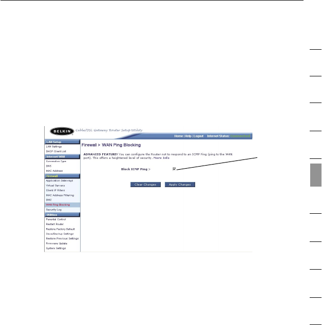
WAN Ping Blocking
Computer hackers use what is known as “pinging” to find potential
victims on the Internet. By pinging a specific IP address and receiving
a response from the IP address, a hacker can determine that
something of interest might be there. The Router can be set up so it
will not respond to an ICMP ping from the outside. This heightens the
level of security of your Router.
To turn off the ping response, select “Block ICMP Ping” (1) and click
“Apply Changes”. The Router will not respond to an ICMP ping.
(1)
4342
Using the Web-Based Advanced User Interface
4342
Using the Web-Based Advanced User Interface
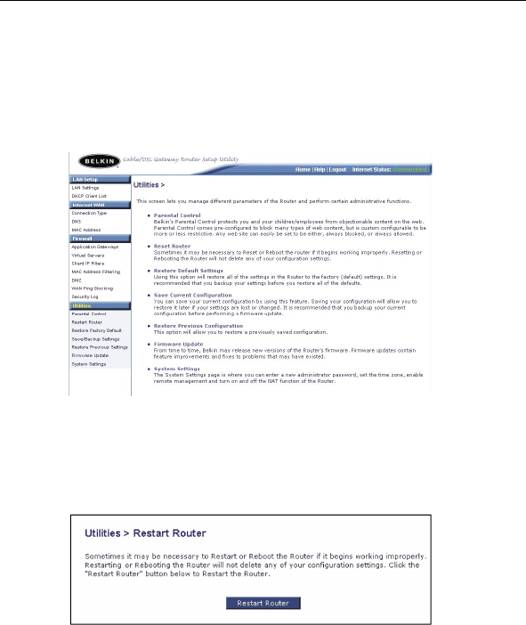
Utilities Tab
This screen lets you manage different parameters of the Router and
perform certain administrative functions.
Restarting the Router
Sometimes it may be necessary to restart or reboot the Router if it
begins working improperly. Restarting or rebooting the Router will
NOT delete any of your configuration settings.
43
Using the Web-Based Advanced User Interface
43
1
2
3
4
5
6
7
8
9
10
11
section
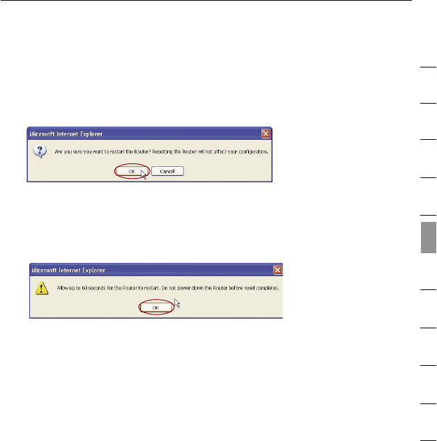
Restarting the Router to Restore Normal Operation
1. Click the “Restart Router” button.
2. The following message will appear. Click “OK”.
3. The following message will appear. Restarting the Router can
take up to 60 seconds. It is important not to turn off the power to
the Router during the restart. Click “OK”.
4. A 60-second countdown will appear on the screen. When the
countdown reaches zero, the Router will be restarted. The Router
home page should appear automatically. If not, type in the
Router’s address (default = 192.168.2.1) into the navigation bar of
your browser.
4544
Using the Web-Based Advanced User Interface
4544
Using the Web-Based Advanced User Interface
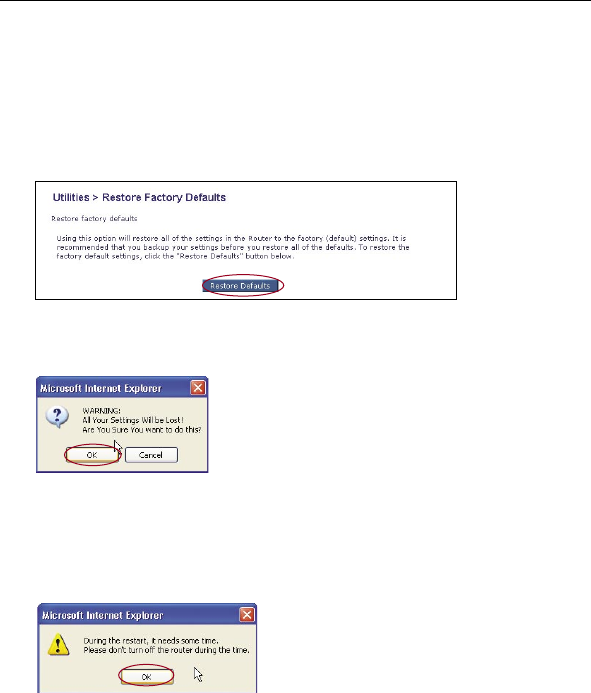
Restoring Factory Default Settings
Using this option will restore all of the settings in the Router to the
factory (default) settings. It is recommended that you back up your
settings before you restore all of the defaults.
1. Click the “Restore Defaults” button.
2. The following message will appear. Click “OK”.
3. The following message will appear. Restoring the defaults
includes restarting the Router. It can take up to 60 seconds.
It is important not to turn the power to the Router off during
the restart or the router could be damaged.
4. A 60-second countdown will appear on the screen. When the
countdown reaches zero, the Router’s defaults will be restored.
The Router’s home page should appear automatically. If it does
not, type in the Router’s address (default = 192.168.2.1) into the
navigation bar of your browser.
45
Using the Web-Based Advanced User Interface
45
1
2
3
4
5
6
7
8
9
10
11
section
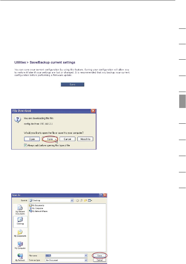
Saving a Current Configuration
You can save your current configuration by using this feature. Saving
your configuration will allow you to restore it later if your settings are
lost or changed. It is recommended that you back up your current
configuration before performing a firmware update.
1. Click “Save”. A window called “File Download” will open.
Click “Save”.
2. A window will open that allows you to select the location where
you want to save the configuration file. Select a location. You
can name the file anything you want, or use the default name
“Config”. Be sure to name the file so you can locate it yourself
later. When you have selected the location and name of the file,
click “Save”.
4746
Using the Web-Based Advanced User Interface
4746
Using the Web-Based Advanced User Interface
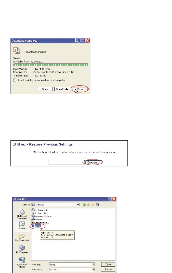
3. When the save is complete, you will see the window below.
Click “Close”.
The configuration is now saved.
Restoring a Previous Configuration
This option will allow you to restore a previously saved configuration.
1. Click “Browse”. A window will open that allows you to select the
location of the configuration file. All configuration files end with a
“.bin”. Locate the configuration file you want to restore and
double-click on it.
47
Using the Web-Based Advanced User Interface
47
1
2
3
4
5
6
7
8
9
10
11
section
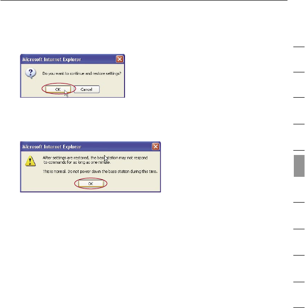
2. You will be asked if you want to continue. Click “OK”.
A reminder window will appear. It will take up to 60 seconds for
the configuration restoration to complete. Click “OK”.
A 60-second countdown will appear on the screen. When the
countdown reaches zero, the Router’s configuration will be
restored. The Router’s home page should appear automatically. If
not, type in the Router’s address (default = 192.168.2.1) into the
navigation bar of your browser.
4948
Using the Web-Based Advanced User Interface
4948
Using the Web-Based Advanced User Interface
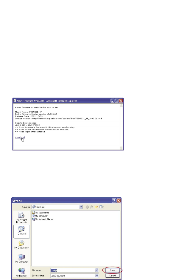
Checking for a New Version of Firmware
The “Check Firmware” (1) button allows you to instantly check for a
new version of firmware. When you click the button, a new browser
window will appear informing you that either no new firmware is
available or that there is a new version available. If a new version is
available, you will have the option to download it.
Downloading a New Version of Firmware
If you click the “Check Firmware” button and a new version of
firmware is available, you will see a screen similar to the one below:
1. To download the new version of firmware, click “Download”.
2. A window will open that allows you to select the location where
you want to save the firmware file. Select a location. You can
name the file anything you want, or use the default name. Be sure
to locate the file in a place where you can locate it yourself later.
When you have selected the location, click “Save”.
49
Using the Web-Based Advanced User Interface
49
1
2
3
4
5
6
7
8
9
10
11
section
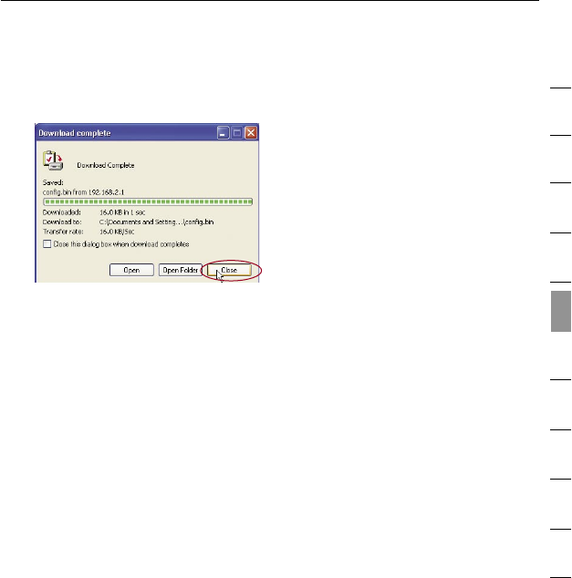
3. When the save is complete, you will see the following window.
Click “Close”.
The download of the firmware is complete. To update the firmware,
follow the next steps in “Updating the Firmware”.
5150
Using the Web-Based Advanced User Interface
5150
Using the Web-Based Advanced User Interface
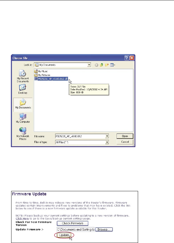
Updating the Firmware
1. In the “Firmware Update” page, click “Browse” (2). A window will
open that allows you to select the location of the firmware
update file.
2. Browse to the firmware file you downloaded. Select the file by
double-clicking on the file name.
3. The “Update Firmware” box will now display the location and
name of the firmware file you just selected. Click “Update”.
51
Using the Web-Based Advanced User Interface
51
1
2
3
4
5
6
7
8
9
10
11
section
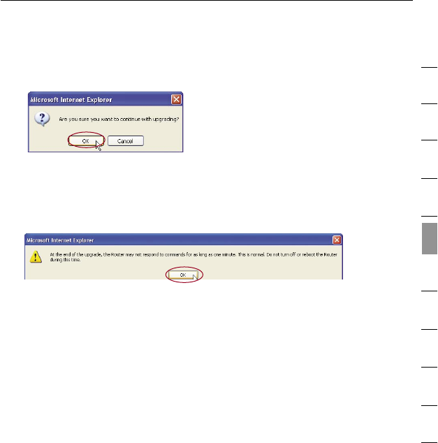
4. You will be asked if you are sure you want to continue.
Click “OK”.
5. You will see one more message. This message tells you that
the Router may not respond for as long as one minute as the
firmware is loaded into the Router and the Router is rebooted.
Click “OK”.
6. A 60-second countdown will appear on the screen. When the
countdown reaches zero, the Router firmware update will be
complete. The Router home page should appear automatically. If
not, type in the Router’s address (default = 192.168.2.1) into the
navigation bar of your browser.
5352
Using the Web-Based Advanced User Interface
5352
Using the Web-Based Advanced User Interface
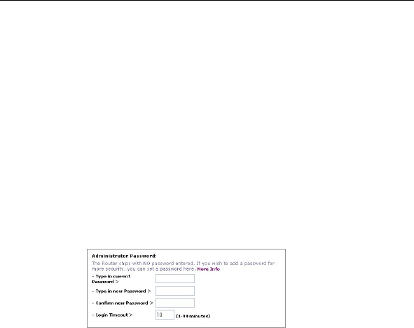
Changing System Settings
The “System Settings” page is where you can enter a new
administrator password, set the time zone, enable remote
management, and turn on and off the NAT function of the Router.
Setting or Changing the Administrator Password
The Router ships with NO password entered. If you wish to add a
password for greater security, you can set a password here. Write
down your password and keep it in a safe place, as you will need it if
you need to log into the Router in the future. It is also recommended
that you set a password if you plan to use the remote management
feature of your Router.
Changing the Login Timeout Setting
The login timeout option allows you to set the period of time that you
can be logged into the Router’s advanced setup interface. The timer
starts when there has been no activity. For example, imagine you have
made some changes in the advanced setup interface, then left your
computer alone without clicking “Logout”. Assuming the timeout is
set to 10 minutes, 10 minutes after you leave, the login session will
expire. You will have to log into the Router again to make anymore
changes. The login timeout option is for security purposes and the
default is set to 10 minutes. Note: Only one computer can be logged
into the Router’s advanced setup interface at one time.
53
Using the Web-Based Advanced User Interface
53
1
2
3
4
5
6
7
8
9
10
11
section
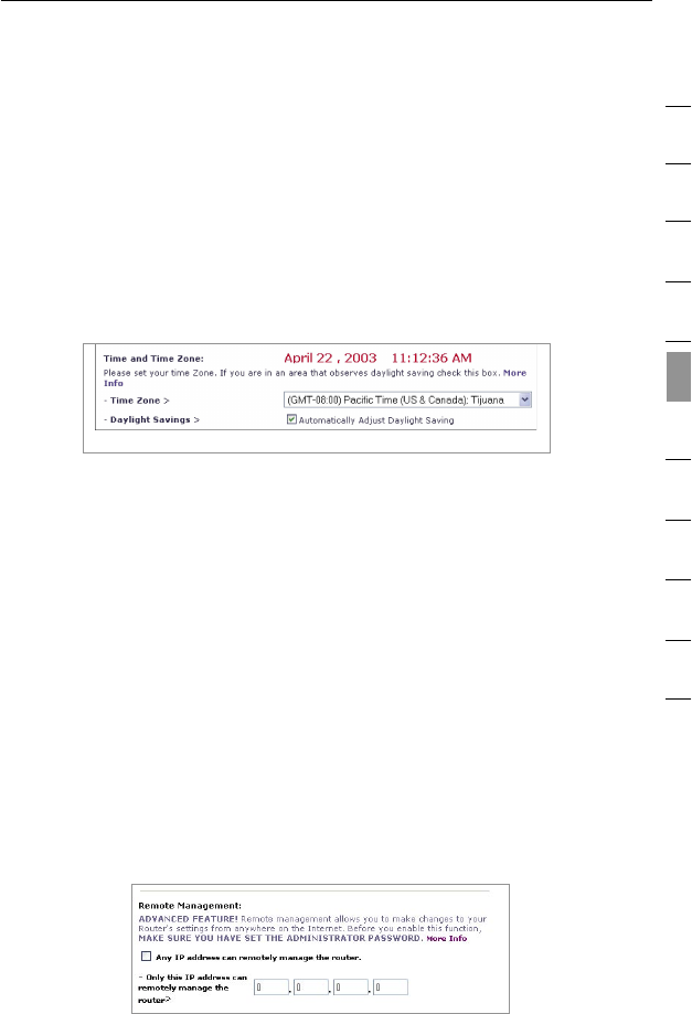
Setting the Time and Time Zone
The Router keeps time by connecting to a Simple Network Time
Protocol (SNTP) server. This allows the Router to synchronize the
system clock to the global Internet. The synchronized clock in the
Router is used to record the security log and control client filtering.
Select the time zone that you reside in. If you reside in an area
that observes daylight saving, then place a check mark in the box
next to “Enable Daylight Saving”. The system clock may not update
immediately. Allow at least 15 minutes for the Router to contact the
time servers on the Internet and get a response. You cannot set the
clock yourself.
Enabling Remote Management
Before you enable this advanced feature of your Belkin Router, MAKE
SURE YOU HAVE SET THE ADMINISTRATOR PASSWORD. Remote
management allows you to make changes to your Router’s settings
from anywhere on the Internet. There are two methods of remotely
managing the Router. The first is to allow access to the Router from
anywhere on the Internet by selecting “Any IP address can remotely
manage the Router”. By typing in your WAN IP address from any
computer on the Internet, you will be presented with a login screen
where you need to type in the password of your Router. The second
method is to allow a specific IP address only to remotely manage the
Router. This is more secure, but less convenient. To use this method,
enter the IP address you know you will be accessing the Router from
in the space provided and select “Only this IP address can remotely
manage the Router”. Before you enable this function, it is STRONGLY
RECOMMENDED that you set your administrator password. Leaving
the password empty will potentially open your Router to intrusion.
5554
Using the Web-Based Advanced User Interface
5554
Using the Web-Based Advanced User Interface
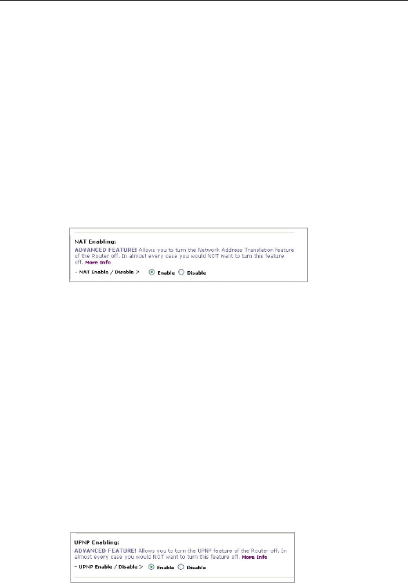
Enabling/Disabling NAT (Network Address Translation)
Note: This advanced feature should be employed by advanced users
only. Before enabling this function, MAKE SURE YOU HAVE SET
THE ADMINISTRATOR PASSWORD. Network Address Translation
(NAT) is the method by which the Router shares the single IP address
assigned by your ISP with the other computers on your network.
This function should only be used if your ISP assigns you multiple
IP addresses or you need NAT disabled for an advanced system
configuration. If you have a single IP address and you turn NAT off,
the computers on your network will not be able to access the Internet.
Other problems may also occur. Turning off NAT will not affect your
firewall functions.
Enabling/Disabling UPnP
UPnP (Universal Plug-and-Play) is yet another advanced feature
offered by your Belkin Router. It is a technology that offers seamless
operation of voice messaging, video messaging, games, and other
applications that are UPnP-compliant. Some applications require
the Router’s firewall to be configured in a specific way to operate
properly. This usually requires opening TCP and UDP ports, and in
some instances, setting trigger ports. An application that is UPnP-
compliant has the ability to communicate with the Router, basically
“telling” the Router which way it needs the firewall configured. The
Router ships with the UPnP feature disabled. If you are using any
applications that are UPnP-compliant, and wish to take advantage of
the UPnP features, you can enable the UPnP feature. Simply select
“Enable” in the “UPnP Enabling” section of the “Utilities” page. Click
“Apply Changes” to save the change.
55
Using the Web-Based Advanced User Interface
55
1
2
3
4
5
6
7
8
9
10
11
section
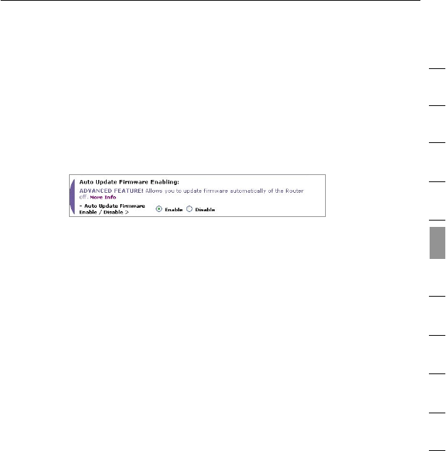
Enabling/Disabling Auto Firmware Update
This innovation provides the Router with the built-in capability to
automatically check for a new version of firmware and alert you
that the new firmware is available. When you log into the Router’s
advanced interface, the Router will perform a check to see if new
firmware is available. If so, you will be notified. You can choose to
download the new version or ignore it.
5756
Manually Configuring Network Settings
5756
Manually Configuring Network Settings
Set up the computer that is connected to the cable or DSL modem
FIRST using these steps. You can also use these steps to add
computers to your Router after the Router has been set up to connect
to the Internet.
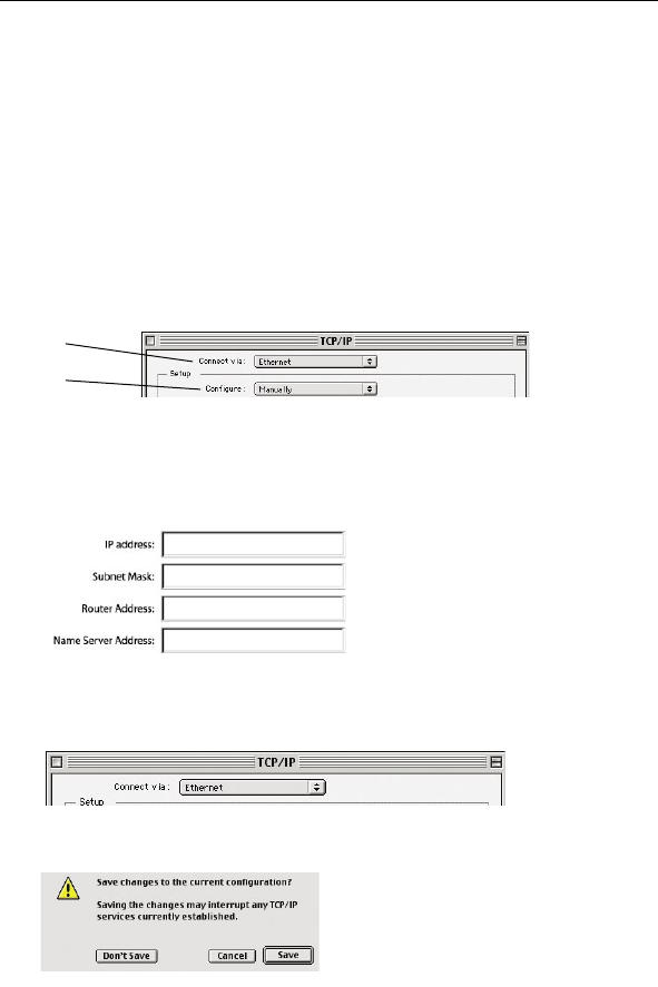
Manually Configuring Network Settings in Mac OS up to 9.x
1. Pull down the Apple® menu. Select “Control Panels” and
select “TCP/IP”.
2. You will see the TCP/IP control panel. Select “Ethernet Built-In”
or “Ethernet” in the “Connect via:” drop-down menu (1).
3. Next to “Configure” (2), if “Manually” is selected, your Router
will need to be set up for a static IP connection type. Write the
address information in the table below. You will need to enter this
information into the Router.
4. If not already set, at “Configure:”, choose “Using DHCP Server”.
This will tell the computer to obtain an IP address from
the Router.
5. Close the window. If you made any changes, the following
window will appear. Click “Save”.
Restart the computer. When the computer restarts, your network
settings are now configured for use with the Router.
(1)
(2)
57
Manually Configuring Network Settings
57
section
1
2
3
4
5
6
7
8
9
10
11
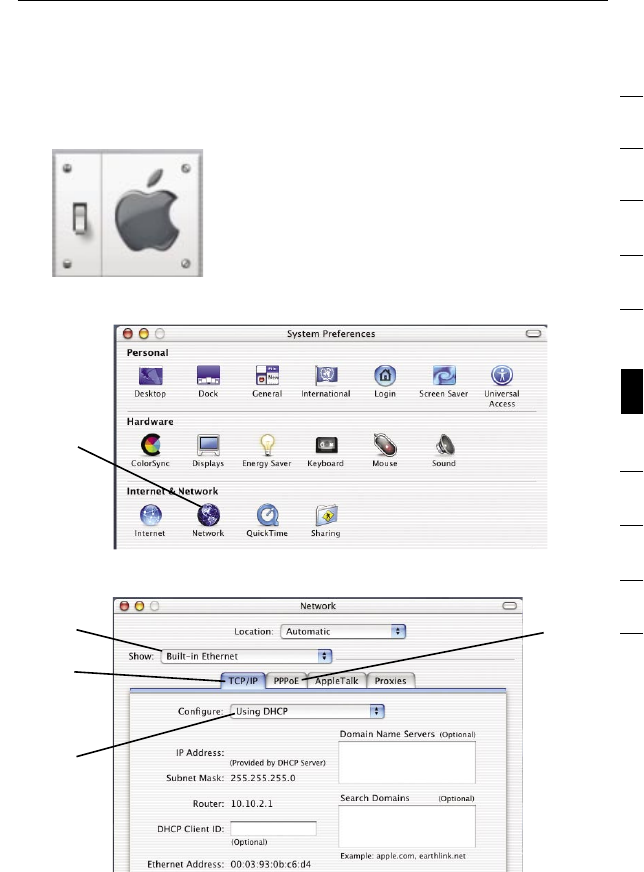
Manually Configuring Network Settings in Mac OS X
1. Click on the “System Preferences” icon.
2. Select “Network” (1) from the “System Preferences” menu.
3. Select “Built-in Ethernet” (2) next to “Show” in the “Network” menu.
4. Select the “TCP/IP” tab (3). Next to “Configure” (4), you should
see “Manually” or “Using DHCP”. If you do not, check the
(2)
(3)
(4)
(5)
(1)
5958
Manually Configuring Network Settings
5958
Manually Configuring Network Settings
PPPoE tab (5) to make sure that “Connect using PPPoE” is NOT
selected. If it is, you will need to configure your Router for a
PPPoE connection type using your user name and password.
5. If “Manually” is selected, your Router will need to be set up for
a static IP connection type. Write the address information in the
table below. You will need to enter this information into
the Router.
6. If not already selected, select “Using DHCP” next to “Configure”
(4), then click “Apply Now”.
Your network settings are now configured for use with the Router.
59
Manually Configuring Network Settings
59
1
2
3
4
5
6
7
8
9
10
11
section
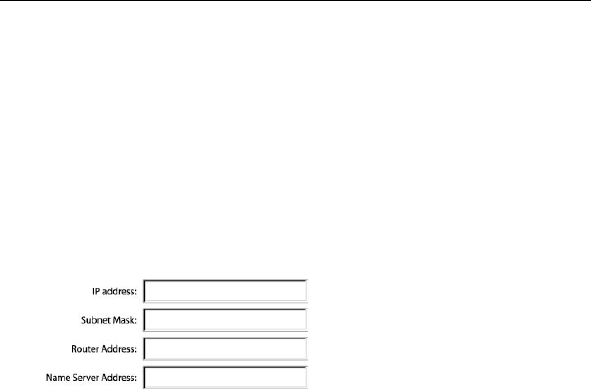
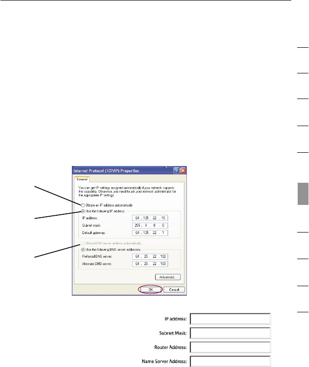
Manually Configuring Network Settings in Windows 2000,
NT, or XP
1. Click “Start”, “Settings”, then “Control Panel”.
2. Double-click on the “Network and dial-up connections” icon
(Windows 2000) or the “Network” icon (Windows XP).
3. Right-click on the “Local Area Connection” associated with your
network adapter and select “Properties” from the drop-down menu.
4. In the “Local Area Connection Properties” window, click “Internet
Protocol (TCP/IP)” and click the “Properties” button. The
following screen will appear:
5. If “Use the following IP
address” (2) is selected, your
Router will need to be set
up for a static IP connection
type. Write the address
information in this table.
You will need to enter this
information into the Router.
6. If not already selected, select “Obtain an IP address
automatically” (1) and “Obtain DNS server address automatically”
(3). Click “OK”.
Your network settings are now configured for use with the Router.
(1)
(2)
(3)
6160
6160
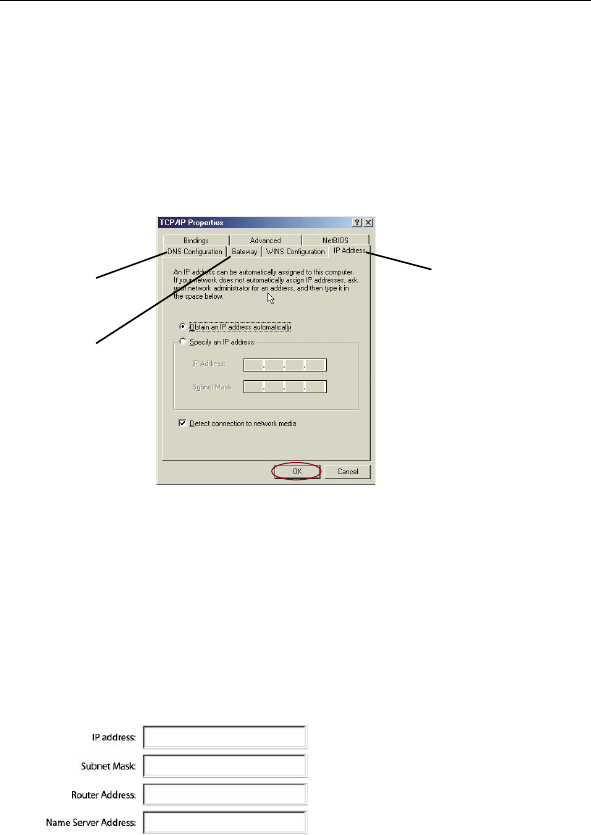
Manually Configuring Network Settings in Windows 98 or Me
1. Right-click on “My Network Neighborhood” and select
“Properties” from the drop-down menu.
2. Select “TCP/IP -> settings” for your installed network adapter.
You will see the following window.
3. If “Specify an IP address” is selected, your Router will need
to be set up for a static IP connection type. Write the address
information in the table below. You will need to enter this
information into the Router.
4. Write the IP address and subnet mask from the “IP Address” tab (3).
5. Click the “Gateway” tab (2). Write the gateway address down in
the chart.
6. Click the “DNS Configuration” tab (1). Write the DNS address(es)
in the chart.
7. If not already selected, select “Obtain IP address automatically”
on the IP address tab. Click “OK”.
Restart the computer. When the computer restarts, your network
settings are now configured for use with the Router.
(2)
(3)
(1)
Manually Configuring Network Settings
61
61
section
1
2
3
4
5
6
7
8
9
10
11
In most cases, you will not need to make any changes to your web
browser’s settings. If you are having trouble accessing the Internet or
the Web-Based Advanced User Interface, then change your browser’s
settings to the recommended settings in this section.
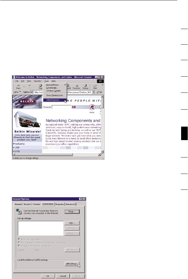
Microsoft® Internet Explorer 4.0 or Higher
1. Start your web browser. Select “Tools” then “Internet Options”.
2. In the “Internet Options” screen, there are three selections:
“Never dial a connection”, “Dial whenever a network connection
is not present”, and “Always dial my default connection”. If you
can make a selection, select “Never dial a connection”. If you
cannot make a selection, go to the next step.
Recommended Web Browser Settings
6362
6362
3. Under the “Internet Options” screen, click on “Connections” and
select “LAN Settings…”.
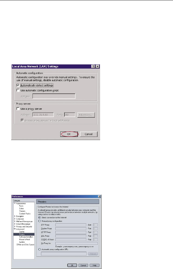
4. Make sure there are no check marks next to any of the displayed
options: “Automatically detect settings”, “Use automatic
configuration script”, and “Use a proxy server”. Click “OK”. Then
click “OK” again in the “Internet Options” page.
Netscape® Navigator® 4.0 or Higher
1. Start Netscape. Click on “Edit” then “Preferences”.
2. In the “Preferences” window, click on “Advanced” then select
“Proxies”. In the “Proxies” window, select “Direct connection to
the Internet”.
Recommended Web Browser Settings

63
63
1
2
3
4
5
6
7
8
9
10
11
section
How to Set Up Your Network to Operate with AOL® for Broadband
and your New Belkin Router
There are two types of AOL connections available—AOL DSL or AOL
Cable. A third service is called AOL BYOA (Bring Your Own Access).
This is used along with an existing broadband connection, supplied
by your Internet Service Provider (ISP). If you have AOL DSL, please
refer to “Directions for AOL DSL Users” below for setup instructions.
If you have either AOL Cable or the AOL BYOA service, please go to
the “Directions for AOL Cable or AOL BYOA Users” section of this
User Manual, on page 70.
Directions for AOL DSL Users
STEP 1: Create AOL screen names for the Router and for each
computer that will be using your AOL service.
STEP 2: Configure the Router for AOL for Broadband.
STEP 3: Configure your computers with the new AOL screen names
you just created.
AOL DSL Users
Step 1 Creating new AOL screen names
Note: Your AOL connections must be set to operate on the TCP/IP
standard. If you have designated another protocol, reset them to
TCP/IP before proceeding.
1. If your Router is currently connected to the network, remove
it from the network and connect it directly to your broadband
modem. Then, log on to AOL as you normally do.
2. Log on to your AOL master account.
Using your Router with AOL for Broadband
6564
Using your Router with AOL for Broadband
6564
Using your Router with AOL for Broadband
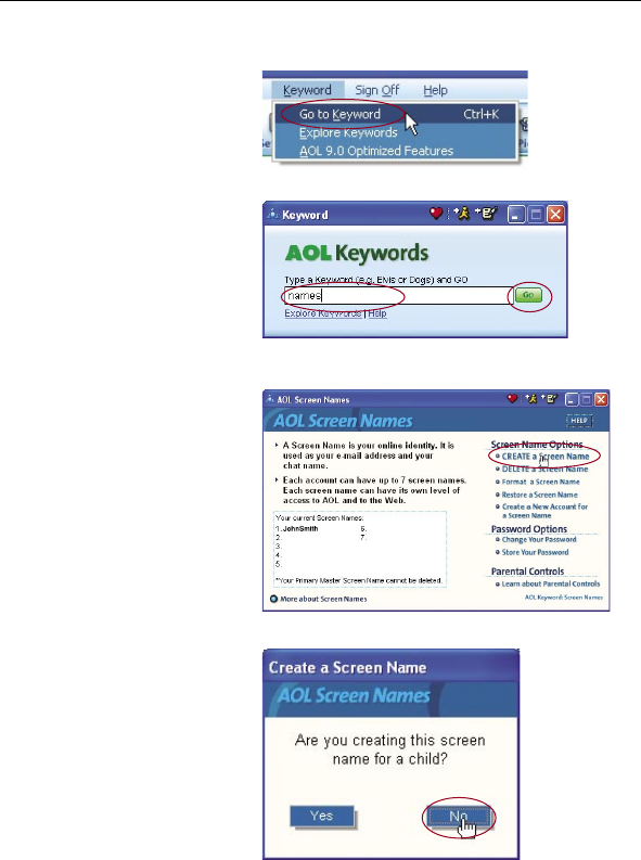
3. Perform a keyword
search on “names” by
clicking “Keyword”, and
then “Go to Keyword”.
4. In the “Keyword”
window, type in
“names” then
click “Go”.
5. You will see the
“AOL Screen Names”
window. Click “CREATE
a Screen Name”.
6. A window will appear
that asks whether
the screen name is
for a child. If you are
creating the screen
name for the Router,
click “Yes” or “No” (it
doesn’t matter which
you select). If you
are creating a screen
name for an additional
computer, select the
appropriate answer.
65
Using your Router with AOL for Broadband
65
1
2
3
4
5
6
7
8
9
10
11
section
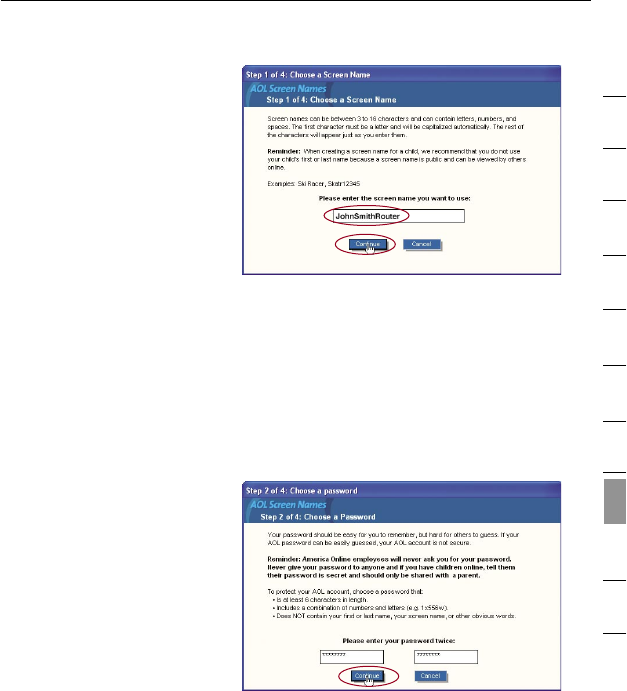
7. The “Choose a Screen
Name” window will
appear. Type in a
screen name, and
click “Continue”. If
this screen name is for
the Router, the name
you choose should be
something like your
master screen name
followed by the word
“Router”. For instance
“JohnSmithRouter”.
If the screen name is
for a computer, type in
the screen name of the
computer for which you
are creating this screen
name. Click “Continue”.
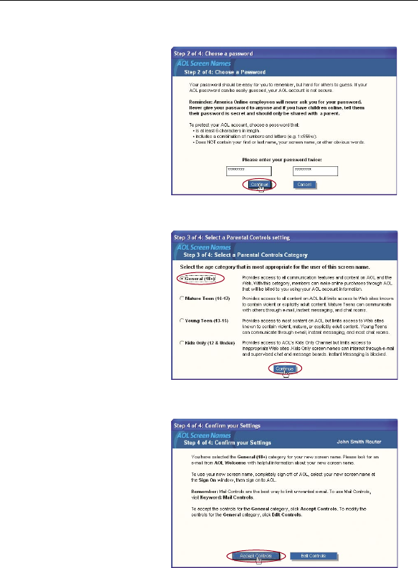
8. The “Choose a
password” screen
will appear. Enter the
password for this
screen name twice, and
click “Continue”.
6766
Using your Router with AOL for Broadband
6766
Using your Router with AOL for Broadband
9. The “Select a Parental
Controls setting”
window will appear. If
this screen name is for
the Router, choose any
one of the settings (it
doesn’t matter which).
If this screen name is
for a computer, choose
the desired setting and
click “Continue”.
10. The “Confirm your
Settings” window will
appear. Select
“Accept Controls”.
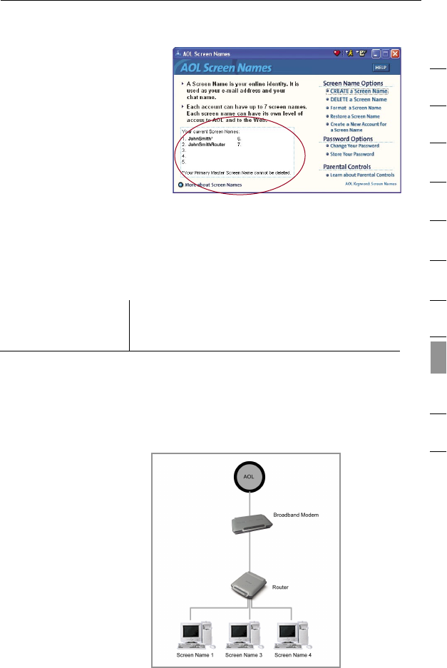
11. The “AOL Screen
Names” window
appears. This window
will include all the
screen names you have
created to this point.
12. Repeat steps 1-11
to add an additional
screen name for each
computer that will be
using AOL and that will
be connected to the
Router. When you are
finished adding screen
names, go to Step 2.
67
Using your Router with AOL for Broadband
67
1
2
3
4
5
6
7
8
9
10
11
section
AOL DSL Users
Step 2 Configuring the Router
Follow this step only if you use AOL DSL. This procedure is for Belkin
Router models F5D5231-4, F5D6231-4, F5D7230-4, and F5D7231-4.
1. Connect your Router to your network per the instructions in your
User Manual.
2. Open your web browser.
3. In the address bar of your browser, type “http://192.168.2.1” and
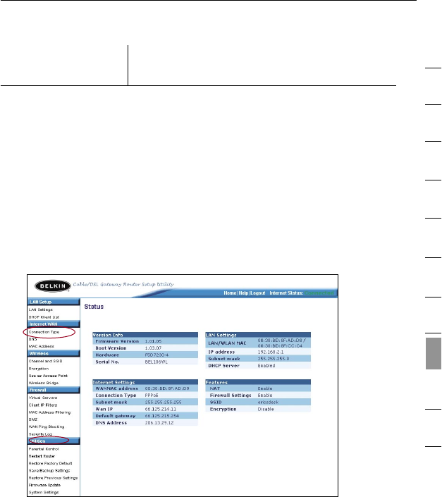
click “Go”. You will be directed to the Router’s home page. Click
on “Connection Type” in the left-hand column under “Internet
WAN” heading.
4. You will see the Router’s login page. Leave the password field
blank and click “Submit”.
5. You will now see the “Connection Type” page. Select “PPPoE”
and click “Next”. You will now see the PPPoE setup page.
6968
Using your Router with AOL for Broadband
6968
Using your Router with AOL for Broadband
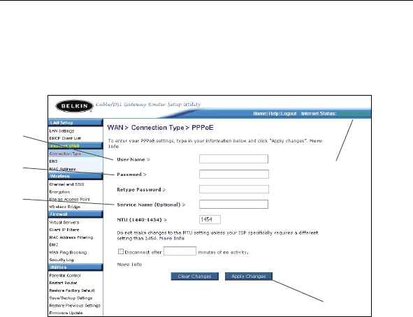
6. In the “User Name” field, type in the screen name that you
created for your Router (1).
7. In the password fields, type in the password you created for the
Router’s screen name (2).
8. Leave the “Service Name” field blank (3). Do not change the
MTU setting.
9. Click on “Apply Changes” (4).
10. Click on the Home link at the top of the screen. The “Internet
Status” indicator should read “Connected” (5).
11. Go to Step 3.
(1)
(2)
(3)
(4)
(5)
69
Using your Router with AOL for Broadband
69
1
2
3
4
5
6
7
8
9
10
11
section
AOL DSL Users
Step 3
Configure your computers with the AOL
screen names you just created
This step consists of installing the AOL software on each computer
and configuring it to use one of the screen names you created in
Step 1. Remember that each computer MUST use a different screen
name. For help installing and configuring the AOL software, contact
AOL’s technical support department.
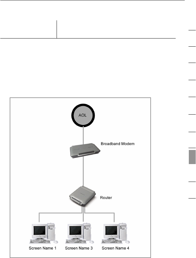
AOL DSL Network Configuration

7170
Using your Router with AOL for Broadband
7170
Using your Router with AOL for Broadband
Directions for AOL Cable or AOL BYOA (Bring Your Own
Access) Users
AOL Cable users need to follow these directions. If you have AOL
DSL, go to the “Directions for AOL DSL Users” section beginning on
page 63.
AOL Cable Users STEP 1:
Create AOL screen names for each computer that will be using
your AOL service.
AOL Cable Users STEP 2:
Configure your computers with the new AOL screen names you
just created.
AOL Cable or
AOL BYOA Users
Step 1
Creating new AOL screen names
Note: Your AOL connections must be set to operate on the TCP/IP
standard. If you have designated another protocol, reset them to
TCP/IP before proceeding.
1. Connect the Router to the network per the instructions in your
User Manual. Once the Router is installed properly, go to the
next step.
2. Log on to your AOL master account.
3. Perform a keyword
search on “names”
by clicking “Keyword”,
and then “Go
to Keyword”.
4. In the “Keyword”
window, type in
“names” then
click “Go”.
71
Using your Router with AOL for Broadband
71
1
2
3
4
5
6
7
8
9
10
11
section
5. You should see the
“AOL Screen Names”
window. Click “CREATE
a Screen Name”.
6. A window will appear
that asks whether the
screen name is for a
child. Click “Yes” or
“No” to answer.
7. The “Choose a Screen
Name” window will
appear. Type in the
screen name of the
computer for which you
are creating this screen
name. Click “Continue”.
7372
Using your Router with AOL for Broadband
7372
Using your Router with AOL for Broadband
8. The “Choose a
password” screen
will appear. Enter the
password for this
screen name twice, and
click “Continue”.
9. The “Select a Parental
Controls setting”
window will appear.
Choose the appropriate
setting for this screen
name. Click “Continue”.
10. The “Confirm your
Settings” window will
appear. Select
“Accept Controls”.
73
Using your Router with AOL for Broadband
73
1
2
3
4
5
6
7
8
9
10
11
section
11. The “AOL Screen
Names” window
appears. This window
will include all the
accounts you have
created to this point.
12. Repeat steps 1-11 for
each computer that
will be using AOL and
that will be connected
to your Belkin Router.
When you are finished
adding screen names,
go to Step 2.
AOL Cable or
AOL BYOA Users
Step 2
Configure your computers with the new
AOL screen names you just created
This step consists of installing the AOL software on each computer
and configuring it to use one of the screen names you created in
Step 1. Remember that each computer MUST use a different screen
name. For help installing and configuring the AOL software, contact
AOL’s technical support department.
AOL Cable or AOL BYOA
Network Configuration

7574
Troubleshooting
7574
Troubleshooting
You can find technical support information at www.belkin.com/
networking or www.belkin.com through the tech support area. If
you want to contact technical support by phone, please call
877-736-5771. Technical support is available 24-hours-a-day,
7-days-a-week.
Problem:
Installation CD does not automatically start.
Solution:
If the CD-ROM does not start the Easy Install Wizard automatically,
it could be that the computer is running other applications that are
interfering with the CD drive.
1. If the Easy Install Wizard screen does not appear within 20
seconds, navigate to your CD-ROM drive by double-clicking on
the “My Computer” icon that is located on your desktop.
2. Next, double-click on the CD-ROM drive (into which you have
placed the Easy Installation CD). Double-click on the file
named “startup.exe”.
3. Easy Install Wizard should start within a few seconds. If, instead,
a window appears showing the files on the CD, double-click on
the icon labeled “Setup”.
4. If the Easy Install Wizard still does not start, reference the
section titled “Manually Configuring Network Settings” on page
56 of this User Manual for an alternate setup method, or contact
Belkin Technical Support toll-free at (877) 736-5771.
Problem:
Easy Install Wizard cannot find my Router.
Solution:
If the Easy Install Wizard is not able to find the Router during the
installation process, please check the following items:
1. If the Easy Install Wizard is not able to find the Router during the
installation process, there may be third-party firewall software
installed on the computer attempting to access the Internet.
Examples of third-party firewall software are ZoneAlarm,
BlackICE PC Protection, McAfee Personal Firewall, and Norton
Personal Firewall.

75
Troubleshooting
75
1
2
3
4
5
6
7
8
9
10
11
section
Troubleshooting
If you do have firewall software installed on your computer,
please make sure that you properly configure it. You can
determine if the firewall software is preventing Internet access
by temporarily turning it off. If, while the firewall is disabled,
Internet access works properly, you will need to change the
firewall settings to function properly when it is turned on.
Please refer to the instructions provided by the publisher of your
firewall software for instructions on configuring the firewall to
allow Internet access.
2. Unplug the Router from its power source (wall outlet) for 10
seconds, and then plug the power back in. Ensure that the
Router’s power light is on; it should be solid green. If it is not,
check to make sure that the AC adapter is properly connected
to the Router and plugged into a wall outlet.
3. Ensure that you have a cable (use the cable included with the
Router) connected between (1) the network (Ethernet) port on
the back of the computer and (2) one of the LAN ports, labeled
“1” through “4”, on the back of the Router.
Note: The computer should NOT be connected to the port
labeled “Internet/WAN” on the back of the Router.
4. Try shutting down and restarting your computer, then rerunning
the Easy Install Wizard.
If the Easy Install Wizard is still unable to find the Router,
reference the section titled “Manually Configuring Network
Settings” on page 56 of this User Manual for an alternate setup
method, or contact Belkin Technical Support toll-free at
(877) 736-5771.
Problem:
Easy Install Wizard cannot connect my Router to the Internet.
Solution:
If the Easy Install Wizard is not able to connect the Router to the
Internet, please check the following items:
1. Use the troubleshooting suggestions within the Easy
Install Wizard. If the troubleshooting screen does not open
automatically, click on the “Troubleshoot” button in the lower
right-hand corner of the Easy Install Wizard window.

7776
Troubleshooting
7776
Troubleshooting
2. If your ISP requires a user name and password, make sure that
you have typed in your user name and password correctly. Some
user names require that the ISP’s domain may be at the end of
the name. Example: “myname@myisp.com”. The “@myisp.com”
part of the user name may need to be typed as well as your
user name.
If you continue to have no Internet connection, reference the
section titled “Manually Configuring Network Settings” on page 56
of this User Manual for an alternate setup method, or contact Belkin
Technical Support toll-free at (877) 736-5771.
Problem:
• The Easy Install Wizard completed installation, but my web
browser doesn’t work.
• I am unable to connect to the Internet. The “WAN” light on my
Router is off, and the “Connected” light is blinking.
Solution:
If you cannot connect to the Internet, and the “WAN” light is off,
and the “Connected” light is blinking, the problem may be that your
modem and Router are not connected properly.
1. Make sure the network cable between the modem and the
Router is connected. We strongly recommend using the cable
that was supplied with your cable or DSL modem for this
purpose. The cable should be connected at one end to the
Router’s “Internet/WAN” port, and at the other end to the
network port on your modem.
2. Unplug the cable or DSL modem from its power source for three
minutes. After three minutes, plug it back in. This may cause the
modem to recognize the Router.
3. Unplug the Router from its power source, wait 10 seconds,
then plug it back in. This will cause the Router to reattempt
communication with the modem.
If the “WAN” light on the Router is not lit after completing these
steps, please contact Belkin Technical Support toll-free at
(877) 736-5771.
Troubleshooting

77
Troubleshooting
77
1
2
3
4
5
6
7
8
9
10
11
section
Problem:
• The Easy Install Wizard completed installation, but my web
browser doesn’t work.
• I am unable to connect to the Internet. The “WAN” light on my
Router is on, and the “Connected” light is blinking.
Solution:
If you cannot connect to the Internet, the “WAN” light is on, and
the “Connected” light is blinking, the problem may be that your
connection type may not match the ISP’s connection.
• If you have a “static IP address” connection, your ISP must
assign you the IP address, subnet mask, and gateway address.
Please refer to the section entitled “Alternate Setup Method” on
page 15 for details on changing this setting.
• If you have a “PPPoE” connection, your ISP will assign you a
user name and password and sometimes a service name. Make
sure the Router connection type is configured to PPPoE and the
settings are entered properly. Please refer the section entitled
“Alternate Setup Method” on page 15 for details on changing
this setting.
• You may need to configure your Router to meet the specific
requirements of your ISP. To search our Knowledge Base for
ISP-specific issues, go to: http://web.belkin.com/support and
type in “ISP”.
If you are still unable to access the Internet after verifying these
settings, please contact Belkin Technical Support.
Troubleshooting

7978
Troubleshooting
7978
Troubleshooting
Troubleshooting
Problem:
• The Easy Install Wizard completed, but my web browser
doesn’t work.
• I am unable to connect to the Internet. The “WAN” light on my
Router is blinking, and the “Connected” light is solid.
Solution:
If the “WAN” light is blinking, and the “Connected” light is solid,
but you are unable to access the Internet, there may be third-party
firewall software installed on the computer attempting to access the
Internet. Examples of third-party firewall software are ZoneAlarm,
BlackICE PC Protection, McAfee Personal Firewall, and Norton
Personal Firewall.
If you do have firewall software installed on your computer, please
make sure that you properly configure it. You can determine if
the firewall software is preventing Internet access by temporarily
turning it off. If, while the firewall is disabled, Internet access works
properly, you will need to change the firewall settings to function
properly when it is turned on.
Please refer to the instructions provided by the publisher of your
firewall software for instructions on configuring the firewall to allow
Internet access.
If you are still unable to access the Internet after disabling any
firewall software, please contact Belkin Technical Support toll-free at
(877) 736-5771.

79
Troubleshooting
79
1
2
3
4
5
6
7
8
9
10
11
section
Troubleshooting
You can find technical support information at
http://www.belkin.com/networking or www.belkin.com through the
tech support area. If you want to contact technical support by phone,
please call:
US: 877-736-5771 or
310-898-1100 ext. 2263
Europe: 00 800 223 55 460
Australia: 1800 235 546
New Zealand: 0800 235 546
Singapore: 800 616 1790

8180
Information
8180 8180
Information
Caution: Exposure to Radio Frequency Radiation.
The radiated output power of this device is far below the FCC radio
frequency exposure limits. Nevertheless, the device shall be used in such
manner that the potential for human contact during normal operation
is minimized.
When connecting an external antenna to the device, the antenna shall be
placed in such a manner to minimize the potential for human contact during
normal operation. In order to avoid the possibility of exceeding the FCC radio
frequency exposure limits, human proximity to the antenna shall not be less
than 20cm (8 inches) during normal operation.
Federal Communications Commission Notice
This equipment has been tested and found to comply with the limits for a
Class B digital device, pursuant to Part 15 of the FCC Rules. These limits are
designed to provide reasonable protection against harmful interference in a
residential installation.
This equipment generates, uses, and can radiate radio frequency energy.
If this equipment does cause harmful interference to radio or television
reception, which can be determined by turning the equipment off and on, the
user is encouraged to try and correct the interference by one or more of the
following measures:
FCC Statement
DECLARATION OF CONFORMITY WITH FCC RULES
FOR ELECTROMAGNETIC COMPATIBILITY
We, Belkin Corporation, of 501 West Walnut Street, Compton,
CA 90220, declare under our sole responsibility that the
product,
F5D5231-4
to which this declaration relates,
complies with Part 15 of the FCC Rules. Operation is subject
to the following two conditions: (1) this device may not cause
harmful interference, and (2) this device must accept any
interference received, including interference that may cause
undesired operation.
8181
81
Information
1
2
3
4
5
6
7
8
9
10
11
section
• Reorient or relocate the receiving antenna.
• Increase the distance between the equipment and the receiver.
• Connect the equipment to an outlet on a circuit
different from that to which the receiver is connected.
• Consult the dealer or an experienced radio/TV
technician for help.
Modifications
The FCC requires the user to be notified that any changes or modifications to
this device that are not expressly approved by Belkin Corporation may void
the user’s authority to operate the equipment.
Canada-Industry Canada (IC)
The wireless radio of this device complies with RSS 139 & RSS 210 Industry
Canada. This Class B digital apparatus complies with Canadian ICES-003.
Cet appareil numérique de la classe B conforme á la norme NMB-003 du Canada.
Europe-European Union Notice
Radio products with the CE 0682 or CE alert marking
comply with the R&TTE Directive (1995/5/EC) issued by the
Commission of the European Community.
Compliance with this directive implies conformity to the following European
Norms (in brackets are the equivalent international standards).
• EN 60950 (IEC60950) – Product Safety
• EN 300 328 Technical requirement for radio equipment
• ETS 300 826 General EMC requirements for radio equipment.
To determine the type of transmitter, check the identification label
on your Belkin product.
Products with the CE marking comply with the EMC Directive (89/336/EEC)
and the Low Voltage Directive (72/23/EEC) issued by the Commission of the
European Community. Compliance with these directives implies conformity
to the following European Norms (in brackets are the equivalent international
standards).
• EN 55022 (CISPR 22) – Electromagnetic Interference
• EN 55024 (IEC61000-4-2,3,4,5,6,8,11) – Electromagnetic Immunity
• EN 61000-3-2 (IEC610000-3-2) – Power Line Harmonics
• EN 61000-3-3 (IEC610000) – Power Line Flicker
• EN 60950 (IEC60950) – Product Safety
Products that contain the radio transmitter are labeled with CE 0682
or CE alert marking and may also carry the CE logo.
Information

PB82
Information
Belkin Corporation Limited Lifetime Product Warranty
Belkin Corporation warrants this product against defects in materials and
workmanship for its lifetime. If a defect is discovered, Belkin will, at its
option, repair or replace the product at no charge provided it is returned
during the warranty period, with transportation charges prepaid, to the
authorized Belkin dealer from whom you purchased the product. Proof of
purchase may be required.
This warranty does not apply if the product has been damaged by accident,
abuse, misuse, or misapplication; if the product has been modified without
the written permission of Belkin; or if any Belkin serial number has been
removed or defaced.
THE WARRANTY AND REMEDIES SET FORTH ABOVE ARE EXCLUSIVE
IN LIEU OF ALL OTHERS, WHETHER ORAL OR WRITTEN, EXPRESSED
OR IMPLIED. BELKIN SPECIFICALLY DISCLAIMS ANY AND ALL IMPLIED
WARRANTIES, INCLUDING, WITHOUT LIMITATION, WARRANTIES OF
MERCHANTABILITY AND FITNESS FOR A PARTICULAR PURPOSE.
No Belkin dealer, agent, or employee is authorized to make any modification,
extension, or addition to this warranty.
BELKIN IS NOT RESPONSIBLE FOR SPECIAL, INCIDENTAL, OR
CONSEQUENTIAL DAMAGES RESULTING FROM ANY BREACH OF
WARRANTY, OR UNDER ANY OTHER LEGAL THEORY, INCLUDING BUT
NOT LIMITED TO, LOST PROFITS, DOWNTIME, GOODWILL, DAMAGE TO
OR REPROGRAMMING OR REPRODUCING ANY PROGRAM OR DATA
STORED IN, OR USED WITH, BELKIN PRODUCTS.
Some states do not allow the exclusion or limitation of incidental or
consequential damages or exclusions of implied warranties, so the above
limitations or exclusions may not apply to you. This warranty gives you
specific legal rights, and you may also have other rights that vary from state
to state.
82

© 2005 Belkin Corporation. All rights reserved. All trade names are registered trademarks
of respective manufacturers listed. Mac, Mac OS, AppleTalk, and Apple are trademarks of
Apple Computer, Inc., registered in the U.S. and other countries.
P74753
4-Port Router
Belkin Ltd.
7 Bowen Crescent, West Gosford
NSW 2250, Australia
+61 (0) 2 4372 8600
+61 (0) 2 4372 8603 fax
Belkin B.V.
Boeing Avenue 333
1119 PH Schiphol-Rijk, The Netherlands
+31 (0) 20 654 7300
+31 (0) 20 654 7349 fax
Belkin Tech Support
US: 877-736-5771
310-898-1100 ext. 2263
Europe: 00 800 223 55 460
Australia: 1800 235 546
New Zealand: 0800 235 546
Singapore: 800 616 1790
Belkin Corporation
501 West Walnut Street
Compton, CA 90220, USA
310-898-1100
310-898-1111 fax
Belkin Ltd.
Express Business Park, Shipton Way
Rushden, NN10 6GL, United Kingdom
+44 (0) 1933 35 2000
+44 (0) 1933 31 2000 fax
Specifications and Standards
Electrical
Power Requirements:
5V, 1.5A
Safety
CSA/NRTL (UL1950, CSA 22.2.950)
GS (EN60950)
CB (IEC60950)
Electromagnetic Compatibility
CE Mark
FCC Class B
VCCI
Environmental
• Temperature:
0 to 40 degrees C (Standard Operating)
-40 to 70 degree C (Non-operation)
Internet Standards
RFC 826 ARP
RFC 791 IP
RFC 792 ICMP
RFC 768 UDP
RFC 793 TCP
RFC 854-859 TELNET
RFC 1321 MD5
RFC 1497 BOOTP Extension
RFC 1570 PPP LCP Extension
RFC 1631 NAT
RFC1661 PPP
RFC 1700 Assigned Numbers
RFC 1866 HTML
RFC 1945 HTTP
RFC 1994 CHAP
RFC 2131 DHCP
RFC 2637 PPTP
NOTE :
This equipment has been tested and found to comply with the limits for a
Class B digital device, pursuant to Part 15 of the FCC Rules. These
limits are designed to provide reasonable protection against harmful
interference in a residential installation. This equipment generates,
uses and can radiated radio frequency energy and, if not installed and
used in accordance with the instructions, may cause harmful interference
to radio communications. However, there is no guarantee that
interference will not occur in a particular installation If this
equipment does cause harmful interference to radio or television
reception, which can be determined by turning the equipment off and on,
the user is encouraged to try to correct the interference by one or more
of the following measures:
-Reorient or relocate the receiving antenna.
-Increase the separation between the equipment and receiver.
-Connect the equipment into an outlet on a circuit different from that
to which the receiver is connected.
-Consult the dealer or an experienced radio/TV technician for help.
Changes or modifications not expressly approved by the party responsible
for compliance could void the user‘s authority to operate the equipment.