Belkin F5D623142 Wireless Cable/DSL Gateway Router User Manual 150000020700ER02 fp
Belkin International, Inc. Wireless Cable/DSL Gateway Router 150000020700ER02 fp
Belkin >
Contents
- 1. Part 1
- 2. Part 2
Part 2

USING THE WEB-BASED ADVANCED USER INTERFACE
41
Using the Accept “ANY” SSID Feature
Note: This advanced feature should be employed by advanced users only. A feature
of wireless networking is the ability to scan for networks and connect to them
easily. For instance, you can set up a wireless-equipped computer to connect to
and an SSID called “ANY”. This forces the wireless network adapter in the computer
to look for any network in the area and connect to it. For ease-of-use this is very
convenient, but in some cases you may want users to have to specify the name of
the network. You can program the Router to reject a wireless-equipped computer
looking for an SSID of “ANY”. Remove the check mark in the box next to “Accept
‘ANY’ SSID”, then click “Apply Changes”. The change is immediate. Each computer
now needs to be set to connect to your specific SSID; an SSID of “ANY” will no
longer be accepted. Refer to the documentation of your wireless network adapter
for information on making this change.
Using the Broadcast SSID Feature
Note: This advanced feature should be employed by advanced users only. For
security, you can choose not to broadcast your network’s SSID. Doing so will keep
your network name hidden from computers that are scanning for the presence of
wireless networks. To turn off the broadcast of the SSID, remove the check mark
from the box next to “Broadcast SSID”, then click “Apply Changes”. The change is
immediate. Each computer now needs to be set to connect to your specific SSID;
an SSID of “ANY” will no longer be accepted. Refer to the documentation of your
wireless network adapter for information on making this change.
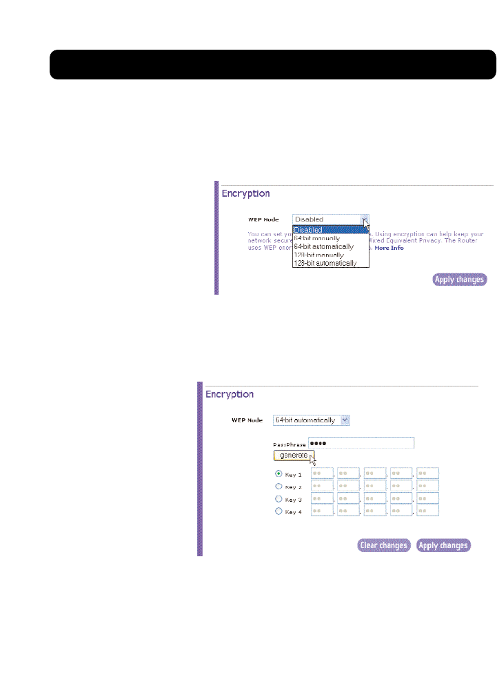
Changing the Wireless Encryption Settings
Clicking on the “Encryption” link in the “Wireless” tab will take you to the
Encryption settings screen. To make setting up your network for the first time easy,
the Router ships with encryption turned off. If you wish to turn on encryption, you
can do so from this page. Turning on encryption will require you to set each of
your wireless-equipped computers with the same encryption settings that you
make in the Router. Refer to the documentation of your wireless network adapter
for information on making this change.
There are two types of encryption to choose from: 64-bit and 128-bit encryption.
Using encryption will make your network more secure, but will slow down the
network performance. Although network performance will be reduced, it is likely
the change will not be detectable to users of the network.
USING THE WEB-BASED ADVANCED USER INTERFACE
42
Setting Encryption Automatically Using a Passphrase
Note to Mac users: The Passphrase option will not operate with Apple® AirPort®. To
configure encryption for your Mac computer, set the encryption using the manual
method described in the next section.
1. Select “64-bit
automatically” or
“128-bit
automatically” from
the drop-down menu.
2. Type in a passphrase. A passphrase is like a password. It can be a mixture
of numbers and letters. After you type in your passphrase, click
“Generate”. When you click “Generate”, the key fields below will become
populated. Note:
64-bit encryption
will generate four
keys and 128-bit
encryption will
generate only one
key. Select the
key you want to
use by clicking
the radio button
next to it. Click
“Apply Changes”.
3. Encryption in the Router is now set. Each of your computers on your
wireless network will now need to be configured with the same
passphrase. Refer to the documentation of your wireless network adapter
for information on making this change.
USING THE WEB-BASED ADVANCED USER INTERFACE
43
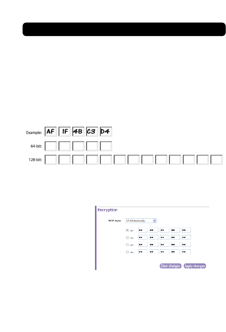
Setting Encryption Manually Using a Hexadecimal Key
A hexadecimal key is a mixture of numbers and letters from A–F and 0–9. 64-bit
keys are five 2-digit numbers. 128-bit keys are 13 2-digit numbers.
For instance:
AF 0F 4B C3 D4 = 64-bit key
C3 03 0F AF 0F 4B B2 C3 D4 4B C3 D4 E7 = 128-bit key
In the boxes below, make up your key by writing in two characters between A–F
and 0–9. You will use this key to program the encryption settings on your Router
and your wireless computers.
Note to Mac users: Original Apple AirPort products support 64-bit encryption only.
Apple AirPort 2 products can support 64-bit or 128-bit encryption. Please check
your product to see which version you are using. If you cannot configure your
network with 128-bit encryption, try 64-bit encryption.
1. Select “64-bit
manually” or “128-bit
manually” from the
drop-down menu.
2. If using 64-bit
encryption, there will
be four key fields. If
using 128-bit
encryption, there will
be one key field. In
the key field(s), type in the hexadecimal key(s) that you wish to use.
When finished typing in your keys, select which key you want to use by
clicking the radio button next to it. Click “Apply Changes”.
3. Encryption in the Router is now set. Each of your computers on your
wireless network will now need to be configured with the same
hexadecimal key. Refer to the documentation of your wireless network
adapter for information on making this change.

USING THE WEB-BASED ADVANCED USER INTERFACE
44
Using the Access Point Mode
Note: This advanced feature should be employed by advanced users only. The
Router can be configured to work as a wireless network access point. Using this
mode will defeat the NAT IP sharing feature and DHCP server. In AP mode, the
Router will need to be configured with an IP address that is in the same subnet
as the rest of the network that you will bridge to. The default IP address is
192.168.2.254 and subnet mask is 255.255.255.0. These can be customized for
your need.
1. Enable the AP mode my selecting “Enable” in the “Use as Access Point only”
page. When you select this option, you will be able to change the IP
settings.
2. Set your IP settings to match your network. Click “Apply Changes”.
3. Connect a cable from the WAN port on the Router to your existing network.
The Router is now acting as an Access Point. To access the Router advanced
user interface again, type the IP address you specified into your browser’s
navigation bar. You can set the encryption settings, MAC address filtering,
SSID and channel normally.

USING THE WEB-BASED ADVANCED USER INTERFACE
45
Configuring the Firewall
Your Router is equipped with a firewall that will protect your network from a
wide array of common hacker attacks including:
•IP Spoofing
•Land Attack
•Ping of Death (PoD)
•Denial of Service (DoS)
•IP with zero length
•Smurf Attack
•TCP Null Scan
•SYN flood
•UDP flooding
•Tear Drop Attack
•ICMP defect
•RIP defect
•Fragment flooding
The firewall also masks common ports that are frequently used to attack networks.
These ports appear to be “Stealth” meaning that for all intents and purposes, they
do not exist to a would-be hacker. You can turn the firewall function off if needed,
however, it is recommended that you leave the firewall enabled. Disabling the
firewall protection will not leave your network completely vulnerable to hacker
attacks, but it is recommended that you leave the firewall enabled.
USING THE WEB-BASED ADVANCED USER INTERFACE
46
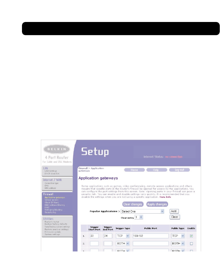
Configuring the Port Forwarding Settings
Application gateways let you select ports to be open for certain applications to
work properly with the Network Address Translation (NAT) feature of the Router.
A list of popular applications has been included to choose from. You can select
an application from the drop-down list and the proper settings will be
programmed into the Router. If the application you want to set up for is not
here, check the “Virtual Servers” page by clicking “Virtual Servers” on the left
side of the screen. If you cannot find your application in either the “Application
Gateways” screen or the “Virtual Servers” screen, you will need to check with the
application vendor to determine which ports need to be configured. You can
manually input this port information into the Router.
USING THE WEB-BASED ADVANCED USER INTERFACE
47
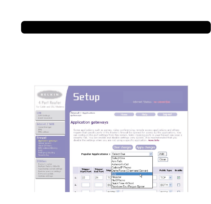
Choosing an Application
Select your application from the drop-down list. Click “Add”. The settings will be
transferred to the next available space in the screen. Click “Apply Changes” to
save the setting for that application. To remove an application, select the
number of the row that you want to remove then click “Clear”.

USING THE WEB-BASED ADVANCED USER INTERFACE
48
Configuring Internal Forwarding Settings
The Virtual Servers function will allow you to route external (Internet) calls for
services such as a web server (port 80), FTP server (Port 21), or other
applications through your Router to your internal network. Since your internal
computers are protected by a firewall, computers outside your network (over the
Internet) cannot get to them because they cannot be “seen”. A list of common
applications has been provided in case you need to configure the Virtual Server
function for a specific application. If your application is not listed, you will need
to contact the application vendor to find out which port settings you need.

USING THE WEB-BASED ADVANCED USER INTERFACE
49
Choosing an Application
Select your application from the drop-down list. Click “Add”. The settings will be
transferred to the next available space in the screen. Click “Apply Changes” to
save the setting for that application. To remove an application, select the
number of the row that you want to remove then click “Clear”.
Manually Entering Settings into the Virtual Server
To manually enter settings, enter the IP address in the space provided for the
internal (server) machine, the port(s) required to pass (use a comma between
multiple ports), select the port type (TCP or UDP), and click “Apply Changes”.
You can only pass one port per internal IP address. Opening ports in your
firewall can pose a security risk. You can enable and disable settings very
quickly. It is recommended that you disable the settings when you are not
using a specific application.
USING THE WEB-BASED ADVANCED USER INTERFACE
50
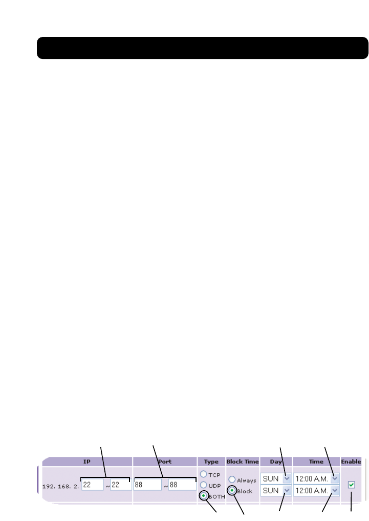
Setting Client IP Filters
The Router can be configured to restrict access to the Internet, e-mail, or other
network services at specific days and times. Restriction can be set for a single
computer, a range of computers, or multiple computers.
To restrict Internet access to a single computer for example, enter the IP address
of the computer you wish to restrict access to in the IP fields (1). Next, enter
“88” in both the port fields (2). Select “Both” (3). Select “Block” (4). You can
also select “Always” to block access all of the time. Select the day to start on
top (5), the time to start on top (6), the day to end on the bottom (7), and
the time to stop (8) on the bottom. Select “Enable” (9). Click “Apply Changes”.
The computer at the IP address you specified will now be blocked from Internet
access at the times you specified. Note: Be sure you have selected the correct
time zone under “Utilities> System Settings> Time Zone”.
(1) (2)
(9)
(3) (4) (7) (8)
(5) (6)
USING THE WEB-BASED ADVANCED USER INTERFACE
51
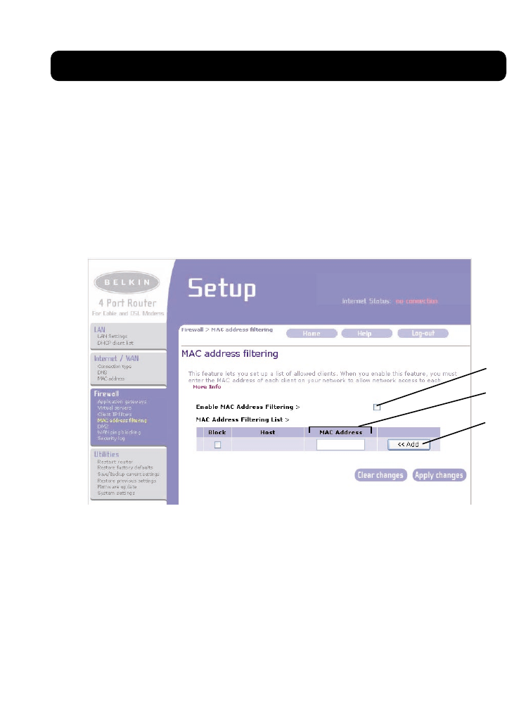
Setting MAC Address Filtering
The MAC address filter is a powerful security feature that allows you to specify
which computers are allowed on the network. Any computer attempting to
access the network that is not specified in the filter list will be denied access.
When you enable this feature, you must enter the MAC address of each client
(computer) on your network to allow network access to each. The “Block”
feature lets you turn on and off access to the network easily for any computer
without having to add and remove the computer’s MAC address from the list.
To enable this feature, select “Enable MAC Address Filtering” (1). Next, enter the
MAC address of each computer on your network by clicking in the space provided
(2) and entering the MAC address of the computer you want to add to the list.
Click “Add” (3), then “Apply Changes” to save the settings. To delete a MAC
address from the list, simply click “Delete” next to the MAC address you wish to
delete. Click “Apply Changes” to save the settings.
Note: You will not be able to delete the MAC address of the computer you are using
to access the Router's administrative functions (the computer you are using now).
(3)
(1)
(2)
USING THE WEB-BASED ADVANCED USER INTERFACE
52
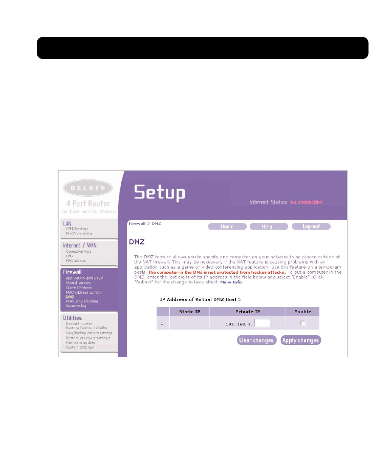
Enabling the Demilitarized Zone (DMZ)
The DMZ feature allows you to specify one computer on your network to be
placed outside of the firewall. This may be necessary if the firewall is causing
problems with an application such as a game or video conferencing application.
Use this feature on a temporary basis. The computer in the DMZ is NOT protected
from hacker attacks.
To put a computer in the DMZ, enter the last digits of its IP address in the IP
field and select “Enable”. Click “Apply Changes” for the change to take effect. If
you are using multiple static WAN IP addresses, it is possible to select which
WAN IP address the DMZ host will be directed to. Type in the WAN IP address you
wish the DMZ host to direct to, enter the last two digits of the IP address of the
DMZ host computer, select “Enable” and click “Apply Changes”.
USING THE WEB-BASED ADVANCED USER INTERFACE
53
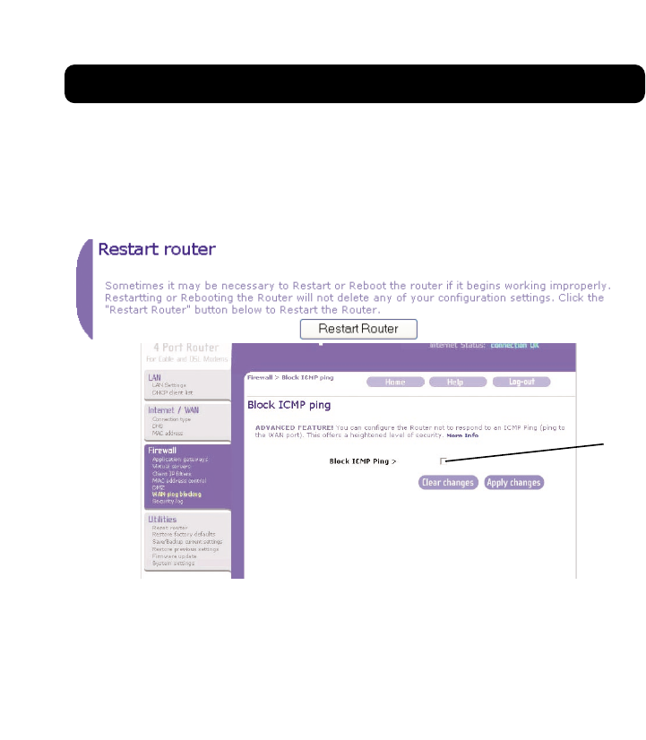
Blocking an ICMP Ping
Computer hackers use what is known as “pinging” to find potential victims on
the Internet. By pinging a specific IP address and receiving a response from the
IP address, a hacker can determine that something of interest might be there.
The Router can be set up so it will not respond to an ICMP ping from the
outside. This heightens the level of security of your Router.
To turn off the ping response, select “Block ICMP Ping” (1) and click “Apply
Changes”. The Router will not respond to an ICMP ping.
(1)

USING THE WEB-BASED ADVANCED USER INTERFACE
54
Utilities Tab
Utilities
This screen lets you manage different parameters of the Router and perform
certain administrative functions.
USING THE WEB-BASED ADVANCED USER INTERFACE
55
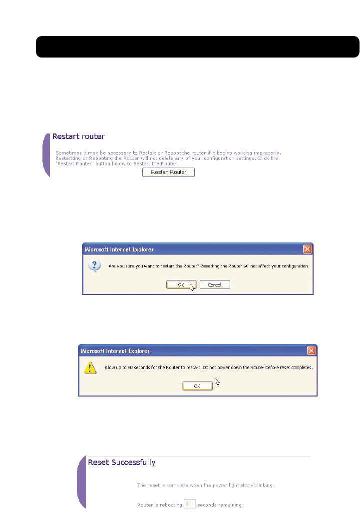
Restarting the Router
Sometimes it may be necessary to restart or reboot the Router if it begins
working improperly. Restarting or rebooting the Router will NOT delete any of
your configuration settings.
Restarting the Router to Restore Normal Operation
1. Click the “Restart Router” button.
2. The following message will appear. Click “OK”.
3. The following message will appear. Restarting the Router can take up to
60 seconds. It is important not to turn off the power to the Router
during the restart.
4. A 60-second countdown will appear on the screen. When the countdown
reaches zero, the Router will be restarted. The Router home page should
appear automatically. If not, type in the Router’s address (default =
192.168.2.1) into the navigation bar of your browser.
USING THE WEB-BASED ADVANCED USER INTERFACE
56
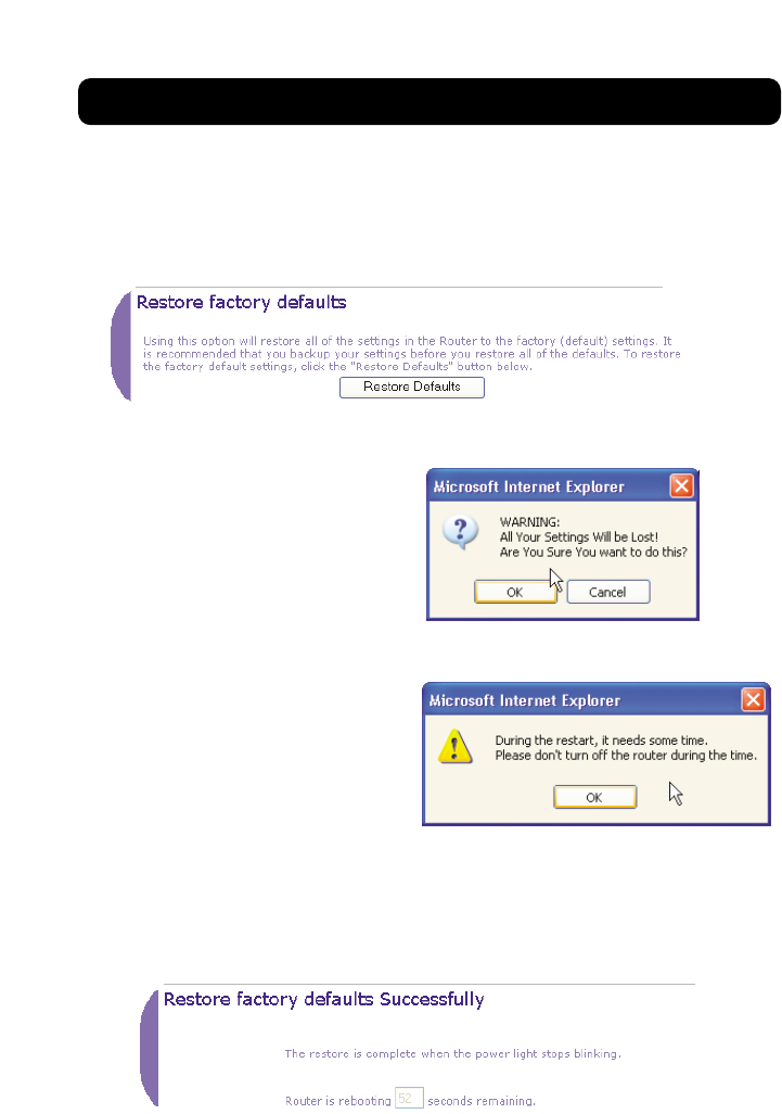
Restoring Factory Default Settings
Using this option will restore all of the settings in the Router to the factory
(default) settings. It is recommended that you back up your settings before you
restore all of the defaults.
1. Click the “Restore Defaults” button.
2. The following message will
appear. Click “OK”.
3. The following message will
appear. Restoring the defaults
includes restarting the Router.
It can take up to 60 seconds.
It is important not to turn the
power to the Router off during
the restart.
4. A 60-second countdown will
appear on the screen. When the countdown reaches zero, the Router’s
defaults will be restored. The Router home page should appear
automatically. If it does not, type in the Router’s address
(default = 192.168.2.1) into the navigation bar of your browser.
USING THE WEB-BASED ADVANCED USER INTERFACE
57
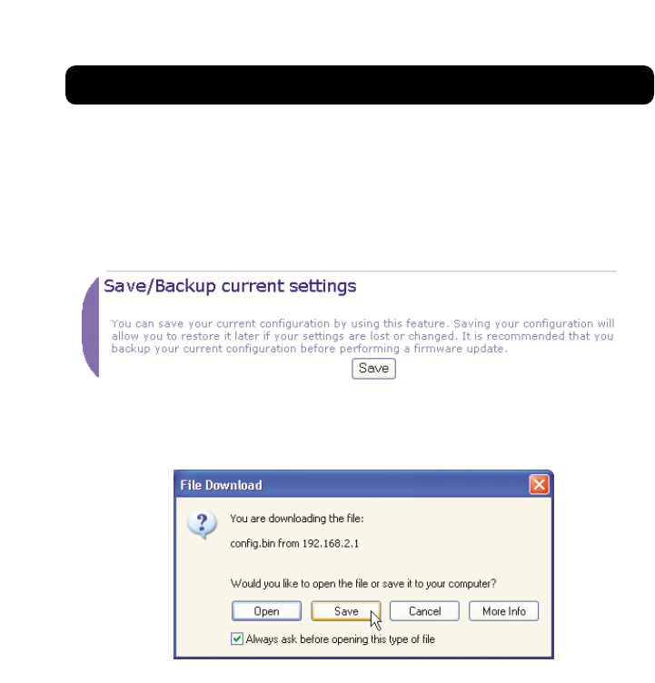
Saving a Current Configuration
You can save your current configuration by using this feature. Saving your
configuration will allow you to restore it later if your settings are lost or
changed. It is recommended that you back up your current configuration before
performing a firmware update.
1. Click “Save”. A window called “File Download” will open. Click “Save”.
USING THE WEB-BASED ADVANCED USER INTERFACE
58
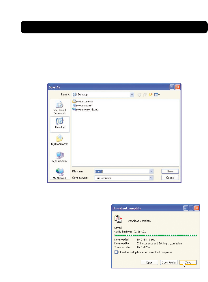
2. A window will open that allows you to select the location where you want
to save the configuration file. Select a location. You can name the file
anything you want, or use the default name “Config”. Be sure to name the
file so you can locate it yourself later. When you have selected the
location and name of the file, click “Save”.
3. When the save is complete,
you will see the window
below. Click “Close”.
The configuration is
now saved.
USING THE WEB-BASED ADVANCED USER INTERFACE
59
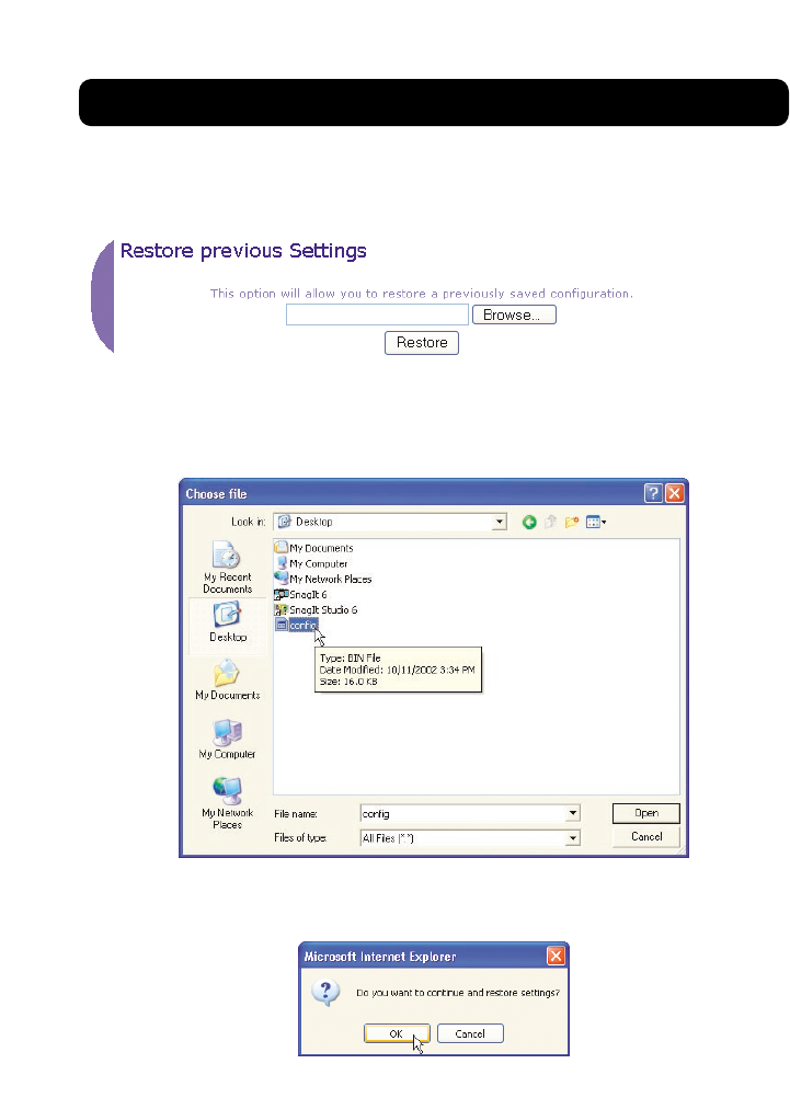
Restoring a Previous Configuration
This option will allow you to restore a previously saved configuration.
1. Click “Browse”. A window will open that allows you to select the location
of the configuration file. All configuration files end with a “.bin”. Locate
the configuration file you want to restore and double-click on it.
2. You will be asked if you want to continue. Click “OK”.
USING THE WEB-BASED ADVANCED USER INTERFACE
60
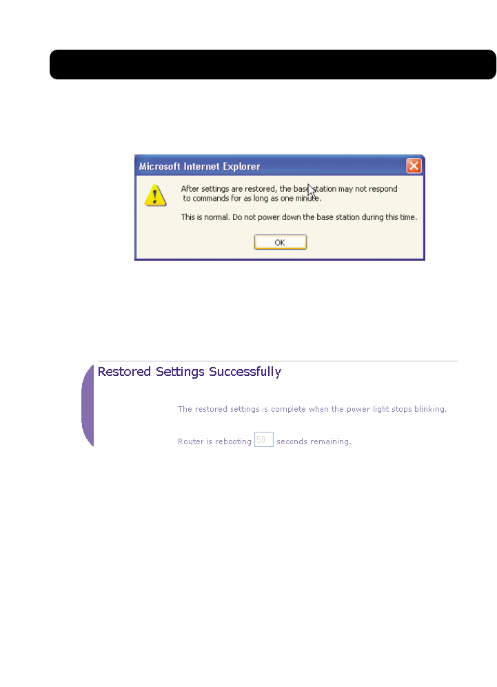
3. A reminder window will appear. It will take up to 60 seconds for the
configuration restoration to complete. Click “OK”.
4. A 60-second countdown will appear on the screen. When the countdown
reaches zero, the Router’s configuration will be restored. The Router home
page should appear automatically. If not, type in the Router’s address
(default = 192.168.2.1) into the navigation bar of your browser.
USING THE WEB-BASED ADVANCED USER INTERFACE
61
Updating Firmware
From time to time, Belkin may release new versions of the Router’s firmware.
Firmware updates contain feature improvements and fixes to problems that
may have existed. When Belkin releases new firmware, you can download the
firmware from the Belkin update website and update your Router’s firmware to
the latest version.
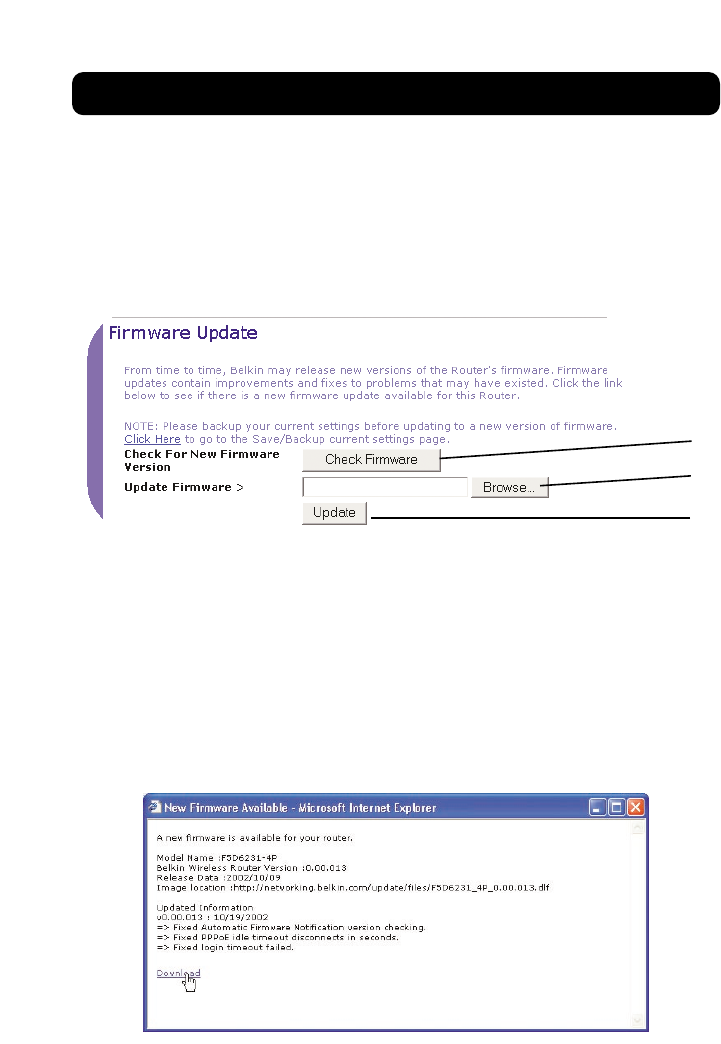
Checking for a New Version of Firmware
The “Check Firmware” (1) button allows you to instantly check for a new version
of firmware. When you click the button, a new browser window will appear
informing you that either no new firmware is available or that there is a new
version available. If a new version is available, you will have the option to
download it.
Downloading a New Version of Firmware
If you click the “Check Firmware” button and a new version of firmware is
available, you will see a screen such as the following.
(3)
(1)
(2)
USING THE WEB-BASED ADVANCED USER INTERFACE
62
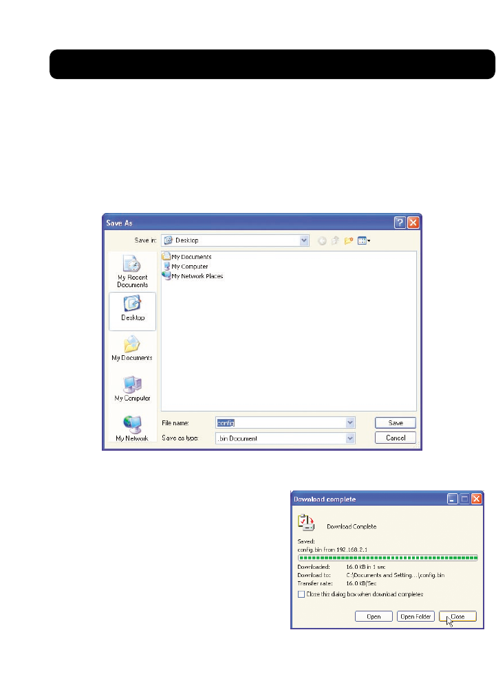
1. To download the new version of firmware, click “Download”.
2. A window will open that allows you to select the location where you want
to save the firmware file. Select a location. You can name the file
anything you want, or use the default name. Be sure to locate the file in
a place where you can locate it yourself later. When you have selected
the location, click “Save”.
3. When the save is complete, you
will see the following window.
Click “Close”.
The download of the firmware is
complete. To update the firmware,
follow the next steps in “Updating
the Router’s Firmware”.
USING THE WEB-BASED ADVANCED USER INTERFACE
63
Updating the Router’s Firmware
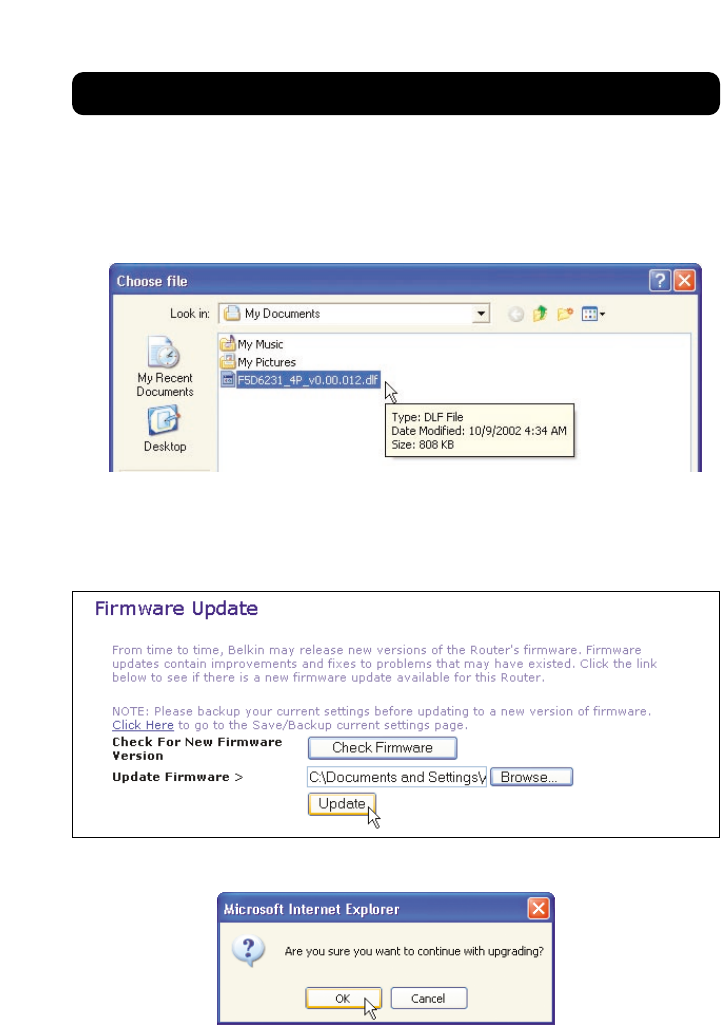
1. In the “Firmware Update” page, click “Browse” (2). A window will open
that allows you to select the location of the firmware update file. All
firmware files end with a “.dlf”.
2. Browse to the firmware file you downloaded. Select the file by double-
clicking on the file name.
3. The “Update Firmware” box will now display the location and name of the
firmware file you just selected. Click “Update”.
4. You will be asked if you are sure you want to continue. Click “OK”.
USING THE WEB-BASED ADVANCED USER INTERFACE
64
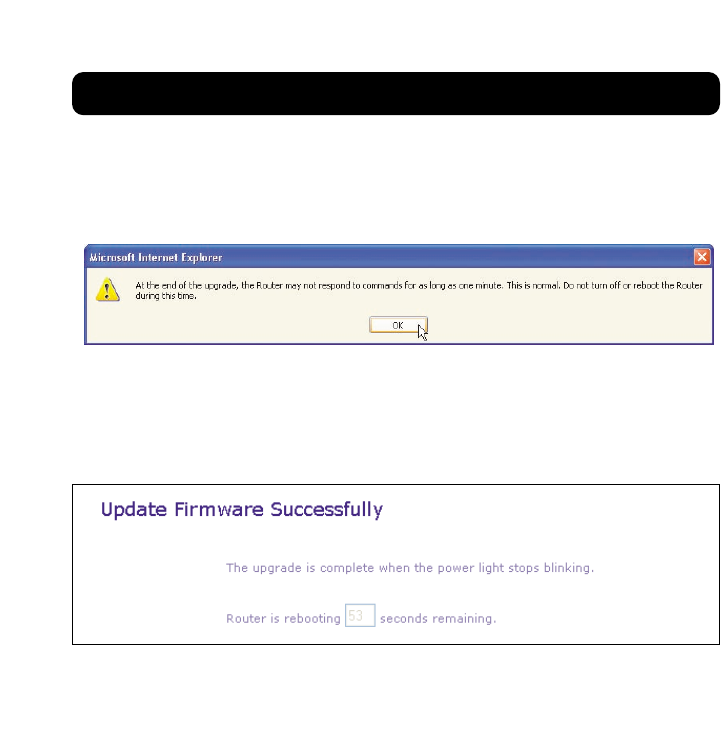
5. You will see one more message. This message tells you that the Router
may not respond for as long as one minute as the firmware is loaded into
the Router and the Router is rebooted. Click “OK”.
6. A 60-second countdown will appear on the screen. When the countdown
reaches zero, the Router firmware update will be complete. The Router
home page should appear automatically. If not, type in the Router’s
address (default = 192.168.2.1) into the navigation bar of your browser.
The firmware update is complete.
USING THE WEB-BASED ADVANCED USER INTERFACE
65
Changing System Settings
The “System Settings” page is where you can enter a new administrator
password, set the time zone, enable remote management, and turn on and off
the NAT function of the Router.
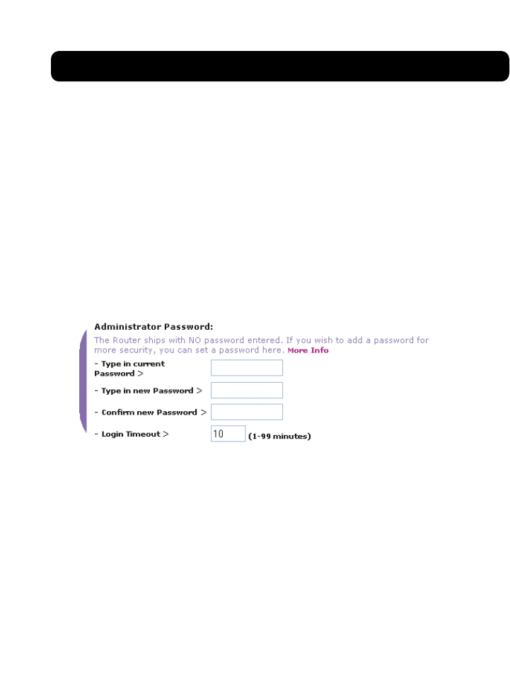
Setting or Changing the Administrator Password
The Router ships with NO password entered. If you wish to add a password for
greater security, you can set a password here. Write down your password and
keep it in a safe place, as you will need it if you need to log into the Router in
the future. It is also recommended that you set a password if you plan to use
the remote management feature of your Router.
Changing the Login Timeout Setting
The login timeout option allows you to set the period of time that you can be
logged into the Router’s advanced setup interface. The timer starts when there
has been no activity. For example, you have made some changes in the advanced
setup interface, then left your computer alone without clicking “Logout”.
Assuming the timeout is set to 10 minutes, then 10 minutes after you leave, the
login session will expire. You will have to login to the Router again to make any
more changes. The login timeout option is for security purposes and the default
is set to 10 minutes.
Note: Only one computer can be logged into the Router’s advanced setup interface
at one time.
USING THE WEB-BASED ADVANCED USER INTERFACE
66
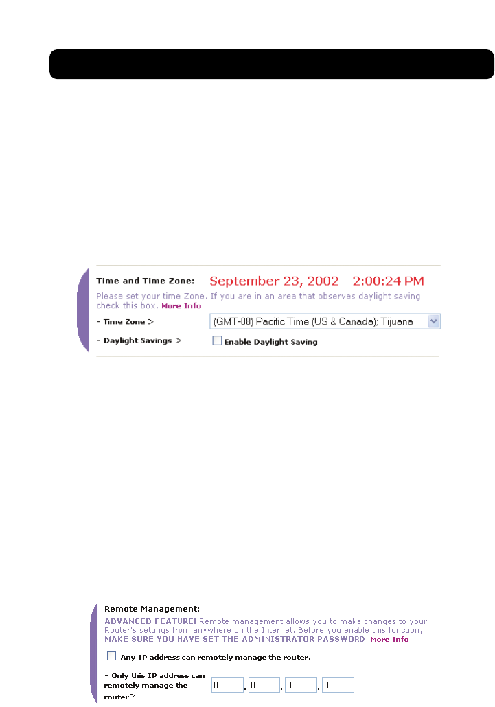
Setting the Time and Time Zone
The Router keeps time by connecting to a Simple Network Time Protocol (SNTP)
server. This allows the Router to synchronize the system clock to the global
Internet. The synchronized clock in the Router is used to record the security log
and control client filtering. Select the time zone that you reside in. If you reside
in an area that observes Daylight Saving, then place a check mark in the box
next to “Enable Daylight Saving”. The system clock may not update immediately.
Allow at least 15 minutes for the Router to contact the time servers on the
Internet and get a response. You cannot set the clock yourself.
Enabling Remote Management
Before you enable this advanced feature of your Belkin Router, MAKE SURE YOU
HAVE SET THE ADMINISTRATOR PASSWORD. Remote management allows you to
make changes to your Router’s settings from anywhere on the Internet. There are
two methods of remotely managing the Router. The first is to allow access to the
Router from anywhere on the Internet by selecting “Any IP address can remotely
manage the Router”. By typing in your WAN IP address from any computer on the
Internet, you will be presented with a login screen where you need to type in
the password of your Router. The second method is to allow a specific IP address
only to remotely manage the Router. This is more secure, but less convenient. To
use this method, enter the IP address you know you will be accessing the Router
from in the space provided and select “Only this IP address can remotely manage
the Router”. Before you enable this function, it is STRONGLY RECOMMENDED that
you set your administrator password. Leaving the password empty will potentially
open your Router to intrusion.
USING THE WEB-BASED ADVANCED USER INTERFACE
67
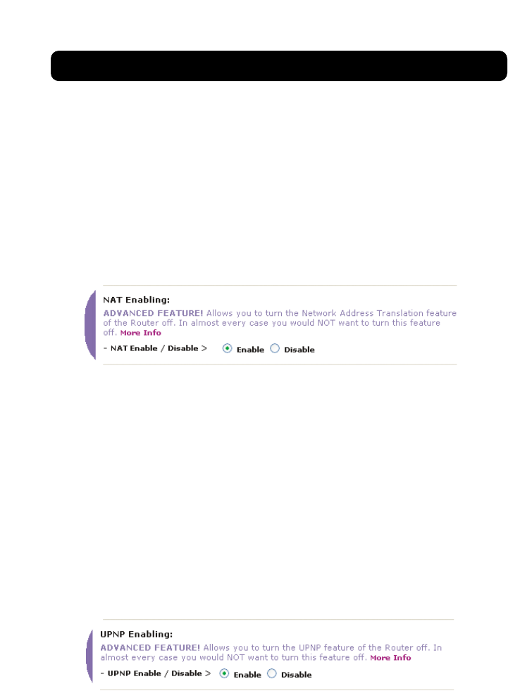
Enabling/Disabling NAT (Network Address Translation)
Note: This advanced feature should be employed by advanced users only. Before
enabling this function, MAKE SURE YOU HAVE SET THE ADMINISTRATOR PASSWORD.
Network Address Translation (NAT) is the method by which the Router shares the
single IP address assigned by your ISP with the other computers on your network.
This function should only be used if your ISP assigns you multiple IP addresses or
you need NAT disabled for an advanced system configuration. If you have a single
IP address and you turn NAT off, the computers on your network will not be able
to access the Internet. Other problems may also occur. Turning off NAT will not
affect your firewall functions.
Enabling/Disabling UPnP
UPnP (Universal Plug-and-Play) is yet another advanced feature offered by your
Belkin Router. It is a technology that offers seamless operation of voice
messaging, video messaging, games, and other applications that are UPnP-
compliant. Some applications require the Router’s firewall to be configured in a
specific way to operate properly. This usually requires opening TCP and UDP
ports, and in some instances, setting trigger ports. An application that is UPnP-
compliant has the ability to communicate with the Router, basically “telling” the
Router which way it needs the firewall configured. The Router ships with the
UPnP feature disabled. If you are using any applications that are UPnP-
compliant, and wish to take advantage of the UPnP features, you can enable the
UPnP feature. Simply select “Enable” in the “UPnP Enabling” section of the
“Utilities” page. Click “Apply Changes” to save the change.
USING THE WEB-BASED ADVANCED USER INTERFACE
68
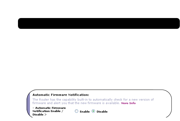
Enabling/Disabling Auto Firmware Update
This innovation provides the Router with the built-in capability to
automatically check for a new version of firmware and alert you that the new
firmware is available. When you log into the Router’s advanced interface, the
Router will perform a check to see if new firmware is available. If so, you will
be notified. You can choose to download the new version or ignore it. The
Router ships with this feature enabled. If you want to disable it, select
“Disable” and click “Apply Changes”.
MANUALLY CONFIGURING NETWORK SETTINGS
69
Set up the computer that is connected to the cable or DSL modem FIRST using
these steps. You can also use these steps to add computers to your Router after
the Router has been set up to connect to the Internet.
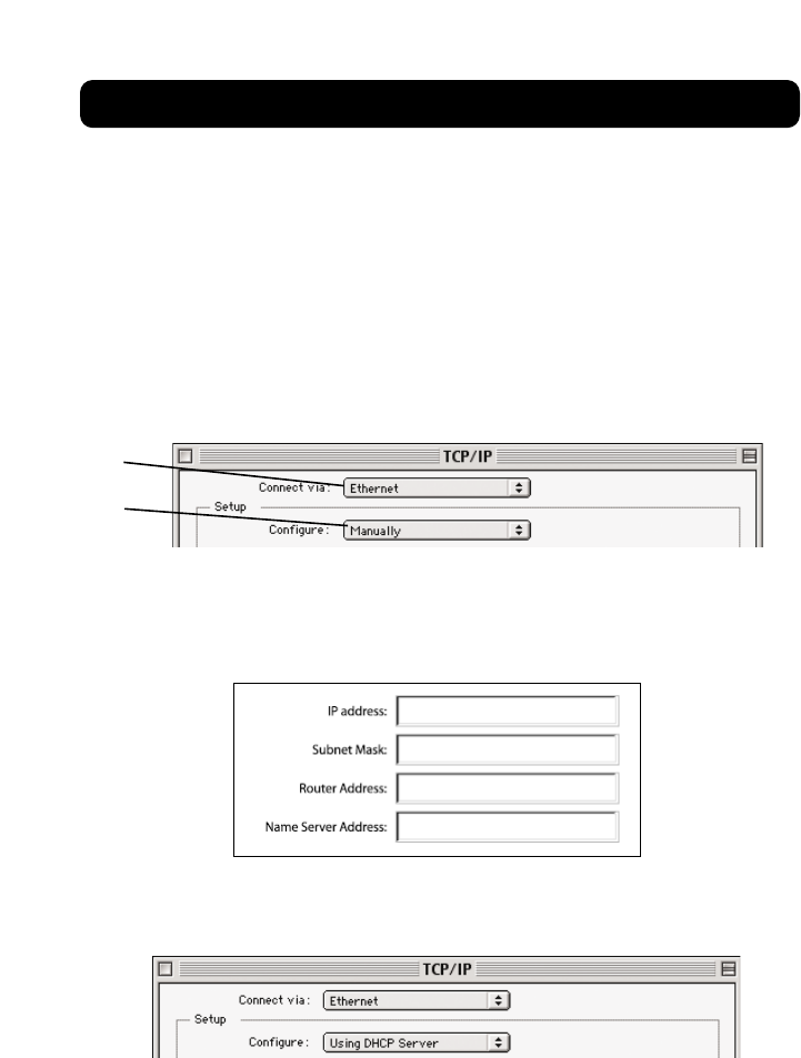
Manually Configuring Network Settings in Mac OS up to 9.x
1. Pull down the Apple menu. Select “Control Panels” and select “TCP/IP”.
2. You will see the TCP/IP control panel. Select “Ethernet Built-In” or
“Ethernet” in the “Connect via:” drop-down menu (1).
3. Next to “Configure” (2), if “Manually” is selected, your Router will need
to be set up for a static IP connection type. Write the address
information in the table below. You will need to enter this information
into the Router.
4. If not already set, at “Configure:”, choose “Using DHCP Server”. This will
tell the computer to obtain an IP address from the Router.
(1)
(2)
MANUALLY CONFIGURING NETWORK SETTINGS
70
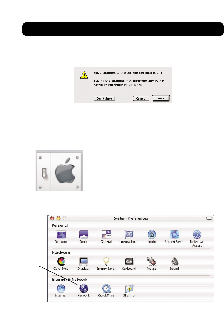
5. Close the window. If you made any changes, the following window will
appear. Click “Save”.
Restart the computer. When the computer restarts, your network settings
are now configured for use with the Router.
Manually Configuring Network Settings in Mac OS X
1. Click on the “System Preferences” icon.
2. Select “Network” (1) from the “System Preferences” menu.
(1)
MANUALLY CONFIGURING NETWORK SETTINGS
71
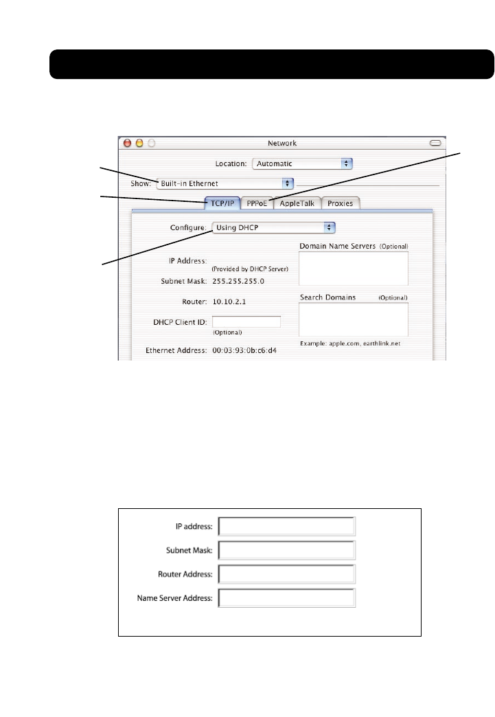
3. Select “Built-in Ethernet” (2) next to “Show in the Network menu.
4. Select the “TCP/IP” tab (3). Next to “Configure” (4), you should see
“Manually” or “Using DHCP”. If you do not, check the PPPoE tab (5) to
make sure that “Connect using PPPoE” is NOT selected. If it is, you will
need to configure your Router for a PPPoE connection type using your
user name and password.
5. If “Manually” is selected, your Router will need to be set up for a static
IP connection type. Write the address information in the table below. You
will need to enter this information into the Router.
6. If not already selected, select “Using DHCP” next to “Configure” (4),
then click “Apply Now”.
Your network settings are now configured for use with the Router.
(2)
(3)
(4)
(5)
MANUALLY CONFIGURING NETWORK SETTINGS
72
Manually Configuring Network Settings in Windows 2000, NT, or XP
1. Click “Start”, “Settings”, then “Control Panel”.
2. Double-click on the “Network and dial-up connections” icon (Windows
2000) or the “Network” icon (Windows XP).
3. Right-click on the “Local Area Connection” associated with your network
adapter and select “Properties” from the drop-down menu.
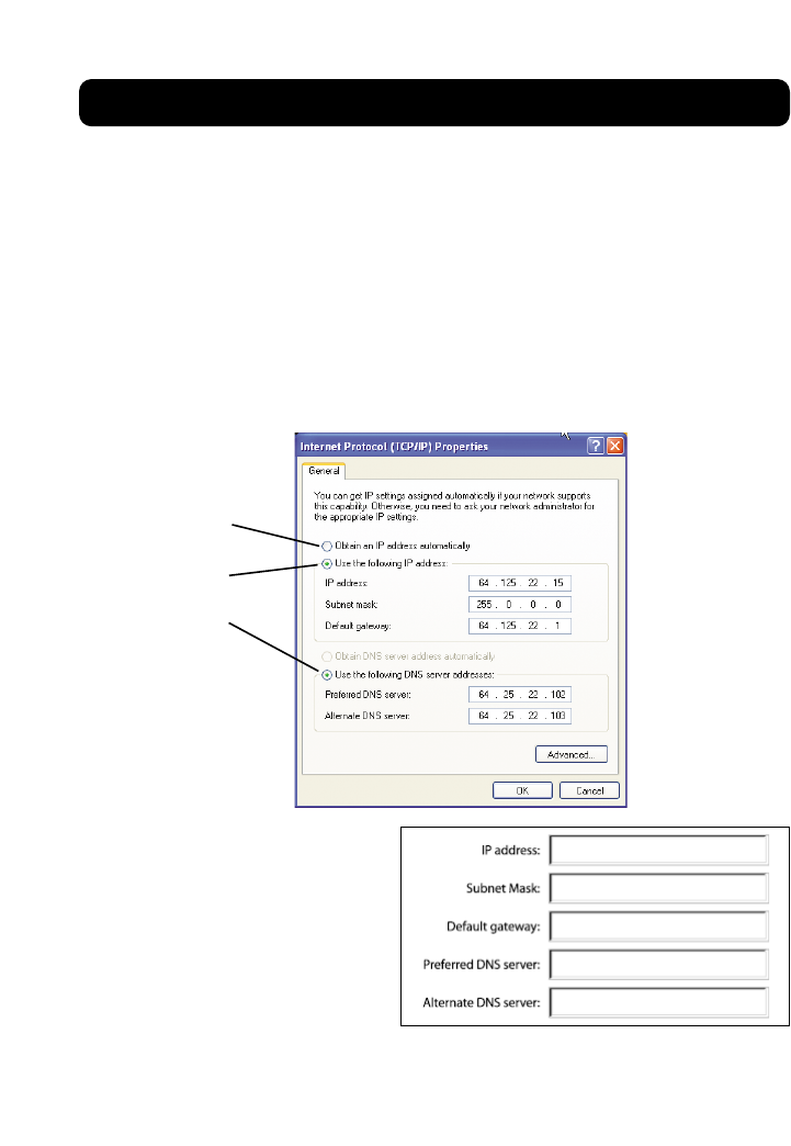
4. In the “Local Area Connection Properties” window, click “Internet
Protocol (TCP/IP)” and click the “Properties” button. The following screen
will appear:
5. If “Use the following IP
address” (2) is selected, your
Router will need to be set up
for a static IP connection
type. Write the address
information the table below.
You will need to enter this
information into the Router.
6. If not already selected, select “Obtain an IP address automatically”(1)
and “Obtain DNS server address automatically” (3). Click “OK”.
Your network settings are now configured for use with the Router.
(2)
(3)
(1)
Manually Configuring Network Settings in Windows 98 or Me
1. Right-click on “My Network Neighborhood” and select “Properties” from the
drop-down menu.
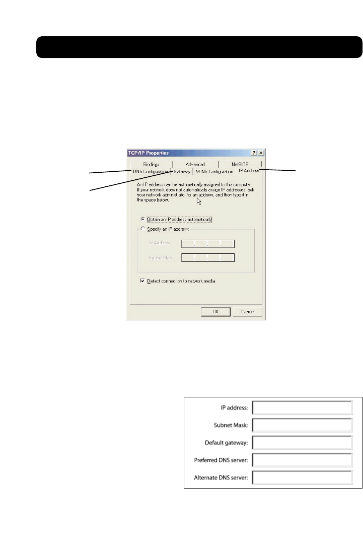
2. Select “TCP/IP -> settings” for your installed network adapter. You will see the
following window.
3. If “Specify and IP address” is selected, your Router will need to be set up for
a static IP connection type. Write the address information in the table below.
You will need to enter this information into the Router.
4. Write the IP address and subnet mask from the “IP Address” tab (3).
5. Click the “Gateway” tab (2). Write the gateway address down in the chart.
6. Click the “DNS Configuration”
tab (1). Write the DNS
address(es) in the chart.
7. If not already selected, select
“Obtain IP address
automatically” on the IP
address tab. Click “OK”.
Restart the computer. When
the computer restarts, your
network settings are now configured for use with the Router.
MANUALLY CONFIGURING NETWORK SETTINGS
73
(2)
(3)
(1)
RECOMMENDED WEB BROWSER SETTINGS
74
In most cases, you will not need to make any changes to your web browser’s
settings. If you are having trouble accessing the Internet or the advanced web-
based user interface, then change your browser’s settings to the recommended
settings in this section.
Internet Explorer 4.0 or Higher
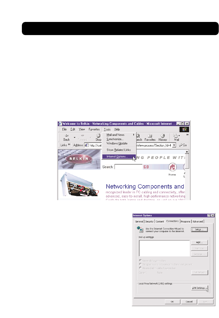
1. Start your web browser. Select “Tools” then “Internet Options”.
2. In the “Internet Options” screen, there are three selections: “Never dial a
connection”, “Dial whenever a
network connection is not
present”, and “Always dial my
default connection”. If you can
make a selection, select “Never
dial a connection”. If you cannot
make a selection, go to the next
step.
3. Under the “Internet Options”
screen, click on “Connections” and
select “LAN Settings…”.
4. Make sure there are no check marks
next to any of the displayed
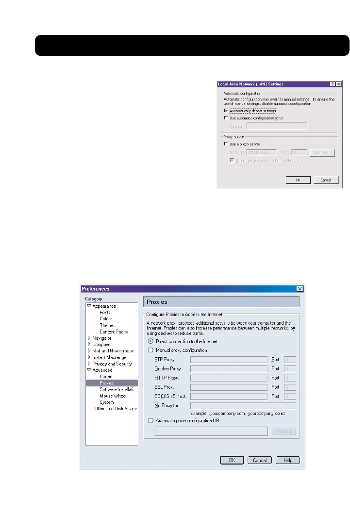
RECOMMENDED WEB BROWSER SETTINGS
75
options: “Automatically detect
settings”, “Use automatic
configuration script”, and “Use a
proxy server”. Click “OK”. Then click
“OK” again in the “Internet
Options” page.
Netscape Navigator 4.0 or Higher
1. Start Netscape. Click on “Edit” then “Preferences”.
2. In the “Preferences” window, click on “Advanced” then select “Proxies”. In
the “Proxies” window, select “Direct connection to the Internet”.

TROUBLESHOOTING
76
You can find technical support information at www.networking.belkin.com or
www.belkin.com through the tech support area. If you want to contact technical
support by phone, please call 800-223-5546. Technical support is available
24-hours-a-day, 7-days-a-week.
The Easy Install Wizard is not able to connect my Router to the Internet.
•The software must be run from the computer that is connected to the modem.
The Internet connection must be active and working at the time of installation.
Connect your computer back to the modem and make sure the Internet
connection is working. Once you have verified that the Internet connection is
working, run the Easy Install Wizard again.
•If your ISP requires a user name and password, make sure that you have typed in
your user name and password correctly. Some user names require that the ISP’s
domain be at the end of the name. Example “myname@myisp.com”. The
“@myisp.com”part of the user name may need to be typed as well as your
user name.
•Make sure that the modem is ON. Check the wall adapter and the power
connection at the modem. Some modems have a power switch. Make sure the
power switch is in the ON position.
The Easy Install Wizard is not able to find my Router.
•Make sure that the Router is ON. The Power/Ready light will be on GREEN and
SOLID. Check the power supply connection at the wall and the Router.
•Make sure that the LAN link light that corresponds to the port you connected to the
computer is ON. Check the network cable going from the computer to the Router.
•If the Easy Install Wizard told you that it detected multiple network adapters,
run the Easy Install Wizard again and try a different adapter.
The WAN link LED is not on or I cannot connect to the cable or DSL modem.
•Check the connection between the Router and the cable or DSL modem. Make
sure the network cable from the cable or DSL modem is connected to the port on
the Router labeled “Internet/WAN”.
•Make sure the cable or DSL modem is powered and switched on.
•Make sure the Router has power. The Power/Ready LED should be illuminated.
•Make sure the cable between the modem and the Router is the cable that was
provided with the modem.

TROUBLESHOOTING
77
My connection type is “static IP address”. I cannot connect to the Internet.
•Since your connection type is “static IP address”, your ISP must assign you the
IP address, subnet mask, and gateway address. Make sure that the Router’s
connection type is configured as “Static IP Address” and verify your settings.
•Your ISP may bind your connection to the MAC address of your computer’s NIC.
Clone your MAC address.
My connection type is “dynamic IP address”. I cannot connect to the Internet.
•Make sure your computers are correctly configured and all network cables are
properly connected.
•Make sure the cable or DSL line is properly attached on your cable or DSL modem.
Refer to the manual of your modem to verify that it works normally.
•Make sure the network cable between the modem and the barricade is well
connected. Power off the modem; wait a few seconds and then power it on again.
•Your ISP may bind your connection to the MAC address of your computer’s NIC.
Clone your MAC address.
My connection type is “PPPoE”. I cannot connect to the Internet.
•Since your connection type is PPPoE, your ISP will assign you a user name and
password and sometimes a service name. Make sure the Router connection type is
configured as “PPPoE” and these settings are entered properly.
•Make sure your computers are correctly configured and all network cables are
properly connected.
•Make sure the coaxial cable or DSL line is properly attached on your cable or DSL
modem. Refer to the manual of your modem to verify it works normally.
•Make sure the network cable between the modem and the Router is well
connected. Power off the modem for a few seconds and power on it again.
•Your ISP may bind your connection to the MAC address of your computer’s NIC.
Clone your MAC address.

INFORMATION
7878
FCC Statement
DECLARATION OF CONFORMITY WITH FCC RULES FOR
ELECTROMAGNETIC COMPATIBILITY
We, Belkin Corporation, of 501 West Walnut Street, Compton, CA 90220, declare under our sole
responsibility that the product,
F5D6231-4
to which this declaration relates,
complies with Part 15 of the FCC Rules. Operation is subject to the following two conditions: (1) this
device may not cause harmful interference, and (2) this device must accept any interference received,
including interference that may cause undesired operation.
Caution: Exposure to Radio Frequency Radiation.
The radiated output power of this device is far below the FCC radio frequency exposure limits.
Nevertheless, the device shall be used in such manner that the potential for human contact
normal operation is minimized.
When connecting an external antenna to the device, the antenna shall be placed in such a
manner to minimize the potential for human contact during normal operation. In order to avoid
the possibility of exceeding the FCC radio frequency exposure limits, human proximity to the
antenna shall not be less than 20cm (8 inches) during normal operation.
Federal Communications Commission Notice
This equipment has been tested and found to comply with the limits for a Class B digital device,
pursuant to Part 15 of the FCC Rules. These limits are designed to provide reasonable protection
against harmful interference in a residential installation.
This equipment generates, uses, and can radiate radio frequency energy. If not installed and used
in accordance with the instructions, it may cause harmful interference to radio or television
reception, which can be determined by turning the equipment off and on, the user is encouraged
to try and correct the interference by one or more of the following measures:
•Reorient or relocate the receiving antenna.
•Increase the distance between the equipment and the receiver.
•Connect the equipment to an outlet on a circuit different from that to which the receiver
is connected.
•Consult the dealer or an experienced radio/TV technician for help.
Modifications
The FCC requires the user to be notified that any changes or modifications to this device that are
not expressly approved by Belkin Corporation may void the users authority to operate the equipment.
INFORMATION
79
Canada- Industry Canada (IC)
The wireless radio of this device complies with RSS 139 & RSS 210 Industry Canada. This Class B
digital complies with Canadian ICES-003.
Cet appareil numérique de la classe B conforme á la norme NMB-003 du Canada.
Europe-European Union Notice
Radio products with the CE 0560 or CE alert marking comply
with the R&TTE Directive (1995/5/EC) issued by the Commission
of the European Community.
Compliance with this directive implies conformity to the following European
Norms (in brackets are the equivalent international
standards).
• EN 60950 (IEC60950) – Product Safety
• EN 300 328 Technical requirement for radio equipment
• ETS 300 826 General EMC requirements for radio equipment.
To determine the type of transmitter, check the identification label on your Belkin product.
Products with the CE marking comply with the EMC Directive (89/336/EEC) and the Low Voltage
Directive (72/23/EEC) issued by the Commission of the European Community.
Compliance with these directives implies conformity to the following European
Norms (in brackets are the equivalent international standards).
• EN 55022 (CISPR 22) – Electromagnetic Interference
• EN 55024 (IEC61000-4-2,3,4,5,6,8,11)- Electromagnetic Immunity
• EN 61000-3-2 (IEC610000-3-2) - Power Line Harmonics
• EN 61000-3-3 (IEC610000) – Power Line Flicker
• EN 60950 (IEC60950) – Product Safety
Products that contain the radio transmitter are labeled with CE 0560 or CE alert marking and may
also carry the CE logo.

INFORMATION
80
Belkin Corporation Limited Lifetime Product Warranty
Belkin Corporation warrants this product against defects in materials and workmanship for its lifetime. If a
defect is discovered, Belkin will, at its option, repair or replace the product at no charge provided it is
returned during the warranty period, with transportation charges prepaid, to the authorized Belkin dealer
from whom you purchased the product. Proof of purchase may be required.
This warranty does not apply if the product has been damaged by accident, abuse, misuse, or misapplication;
if the product has been modified without the written permission of Belkin; or if any Belkin serial number has
been removed or defaced.
THE WARRANTY AND REMEDIES SET FORTH ABOVE ARE EXCLUSIVE IN LIEU OF ALL OTHERS, WHETHER ORAL OR
WRITTEN, EXPRESSED OR IMPLIED. BELKIN SPECIFICALLY DISCLAIMS ANY AND ALL IMPLIED WARRANTIES,
INCLUDING, WITHOUT LIMITATION, WARRANTIES OF MERCHANTABILITY AND FITNESS FOR A PARTICULAR PURPOSE.
No Belkin dealer, agent, or employee is authorized to make any modification, extension, or addition to
this warranty.
BELKIN IS NOT RESPONSIBLE FOR SPECIAL, INCIDENTAL, OR CONSEQUENTIAL DAMAGES RESULTING FROM ANY
BREACH OF WARRANTY, OR UNDER ANY OTHER LEGAL THEORY, INCLUDING BUT NOT LIMITED TO, LOST PROFITS,
DOWNTIME, GOODWILL, DAMAGE TO OR REPROGRAMMING, OR REPRODUCING ANY PROGRAM OR DATA STORED
IN, OR USED WITH, BELKIN PRODUCTS.
Some states do not allow the exclusion or limitation of incidental or consequential damages or exclusions of
implied warranties, so the above limitations of exclusions may not apply to you. This warranty gives you
specific legal rights, and you may also have other rights that vary from state to state.

Belkin Corporation
501 West Walnut Street
Compton • CA • 90220 • USA
Tel: 310.898.1100
Fax: 310.898.1111
Belkin Components, Ltd.
Express Business Park
Shipton Way • Rushden • NN10 6GL
United Kingdom
Tel: +44 (0) 1933 35 2000
Fax: +44 (0) 1933 31 2000
Belkin Components B.V.
Starparc Building • Boeing Avenue 333
1119 PH Schiphol-Rijk • The Netherlands
Tel: +31 (0) 20 654 7300
Fax: +31 (0) 20 654 7349
Belkin Components, Ltd.
7 Bowen Crescent • West Gosford
NSW 2250 • Australia
Tel: +61 (0) 2 4372 8600
Fax: +61 (0) 2 4372 8603
Belkin Tech Support
US: 310.898.1100 ext. 2263
800.223.5546 ext. 2263
Europe: 00 800 223 55 460
Australia: 1800 666 040
P74122-A
© 2002 Belkin Corporation. All rights reserved. All trade names are
registered trademarks of respective manufacturers listed.
belkin.com
150000020700E R02