Belkin F5D7230E Wireless G Router User Manual P74559 G F5D7230 4 manual indd
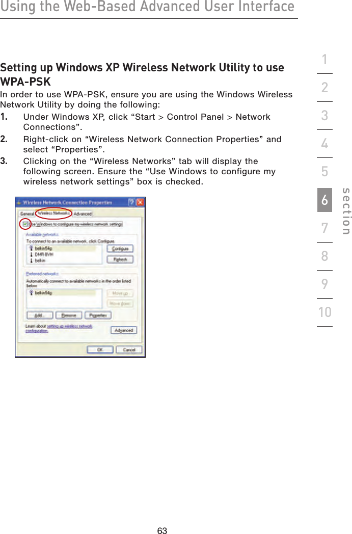
Belkin International, Inc. Wireless G Router P74559 G F5D7230 4 manual indd
Belkin >
Contents
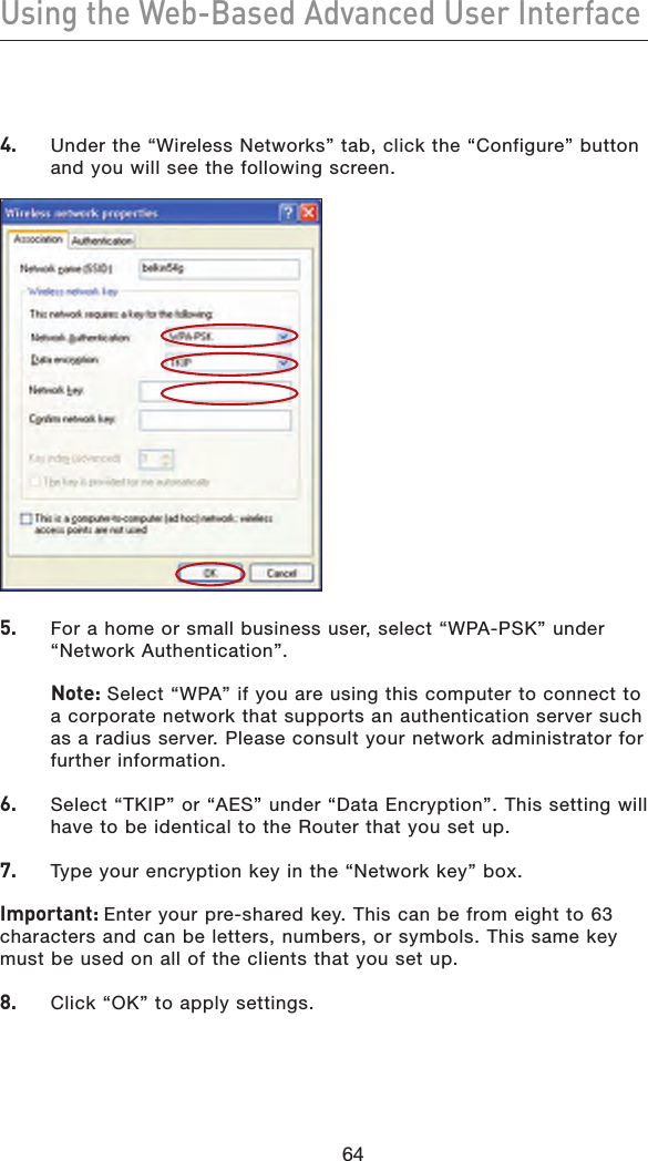
- 1. Users Manual 1
- 2. Users Manual 2
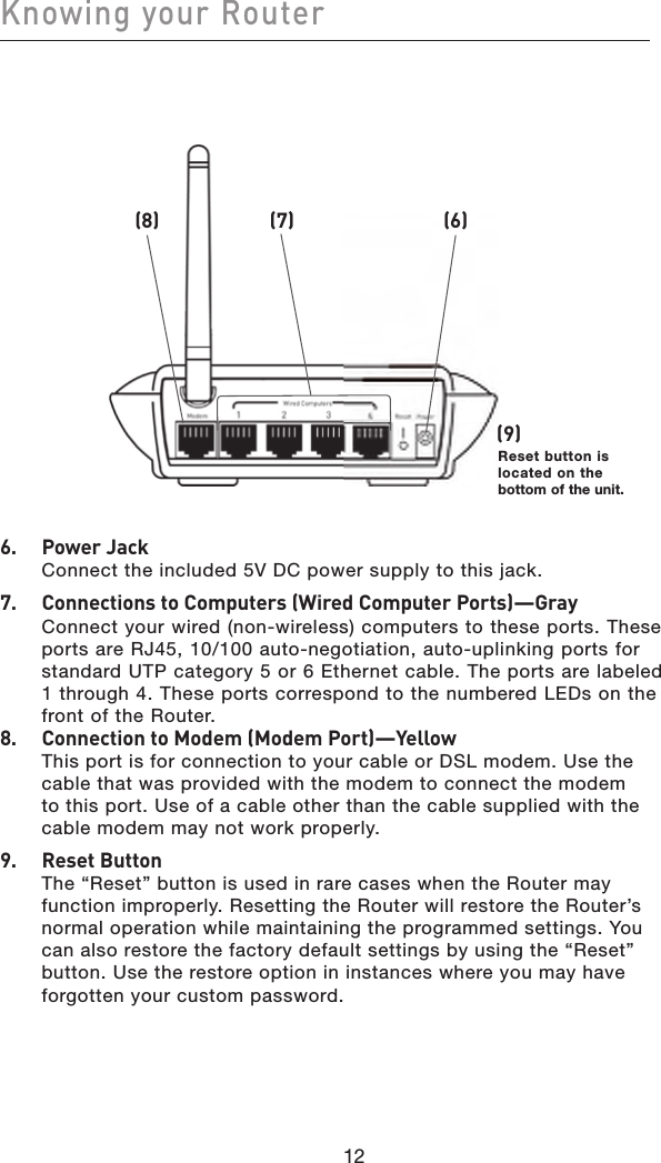
- 3. Users Manual 3
Users Manual 1

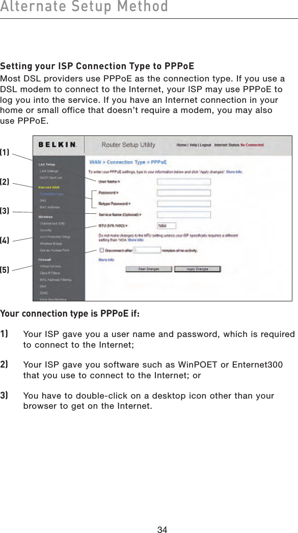
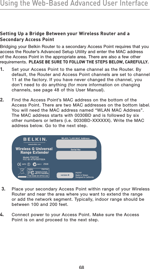
![36Alternate Setup Method36Setting your Internet Service Provider (ISP) Connection Type to Point-to-Point Tunneling Protocol (PPTP)[European Countries Only]. Some ISPs require a connection using PPTP protocol, a type of connection most common in European countries. This sets up a direct connection to the ISP’s system. Type the information provided by your ISP in the space provided. When you have finished, click “Apply Changes”. After you apply the changes, the “Internet Status” indicator will read “connection OK” if your Router is set up properly.(1)(2)(3)(4)(5)(6)(7)(8)(9)1. PPTP Account Provided by your ISP. Enter your PPTP User ID here.2. PPTP Password Type in your password and retype it into the “Retype Password” box to confirm it.3. Host Name Provided by your ISP. Enter your host name here.4. Service IP Address Provided by your ISP. Enter your PPTP gateway/service IP address here.](https://usermanual.wiki/Belkin/F5D7230E.Users-Manual-1/User-Guide-902461-Page-40.png)
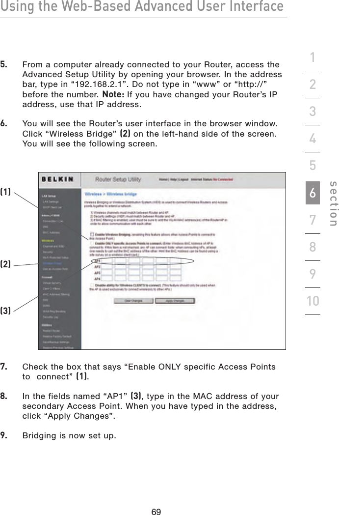
![38Alternate Setup Method38Setting your Connection Type if you are a Telstra® BigPond User[Australia Only]. Your user name and password are provided to you by Telstra BigPond. Enter this information below. Choosing your state from the drop-down menu (6) will automatically fill in your login server IP address. If your login server address is different than the one provided here, you may manually enter the login server IP address by placing a check in the box next to “User decide login server manually” (4) and type in the address next to “Login Server” (5). When you have entered all of your information, click “Apply Changes”. After you apply the changes, the “Internet Status” indicator will read “connection OK” if your Router is set up properly.(1)(2)(3)(4)(5)(6)1. Select your State Select your state from the drop-down menu (6). The “Login Server” box will automatically be filled in with an IP address. If for some reason this address does not match the address that Telstra has given, you can manually enter the login server address. See “User decide login server manually” (4).2. User Name Provided by your ISP. Type in your user name here.3. Password Type in your password and retype it into the “Retype Password” box to confirm it.](https://usermanual.wiki/Belkin/F5D7230E.Users-Manual-1/User-Guide-902461-Page-42.png)

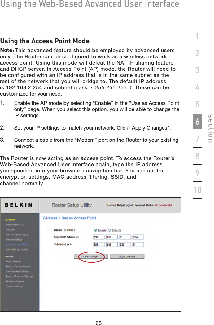
![71707170Using the Web-Based Advanced User Interfacesection19234567810Configuring Internal Forwarding SettingsThe “Virtual Servers” function will allow you to route external (Internet) calls for services such as a web server (port 80), FTP server (Port 21), or other applications through your Router to your internal network. Since your internal computers are protected by a firewall, computers outside your network (over the Internet) cannot get to them because they cannot be “seen.” You will need to contact the application vendor to find out which port settings you need.Entering Settings into the Virtual ServerTo enter settings, enter the IP address in the space provided for the internal (server) machine, and the port(s) required to pass. Then select the port type (TCP or UDP), check the “Enable” box, and click “Apply Changes”. Each inbound port entry has two fields with five characters maximum per field that allows a start and end port range, e.g. [xxxxx]-[xxxxx]. For each entry, you can enter a single port value by filling in the two fields with the same value (e.g. [7500]-[7500]) or a wide range of ports (e.g. [7500]-[9000]). If you need multiple single port values or a combination of ranges and a single value, you must use multiple entries up to the maximum of 20 entries (e.g. 1. [7500]-[7500], 2. [8023]-[8023], 3. [9000]-[9000]). You can only pass one port per internal IP address. Opening ports in your firewall can pose a security risk. You can enable and disable settings very quickly. It is recommended that you disable the settings when you are not using a specific application.](https://usermanual.wiki/Belkin/F5D7230E.Users-Manual-1/User-Guide-902461-Page-75.png)