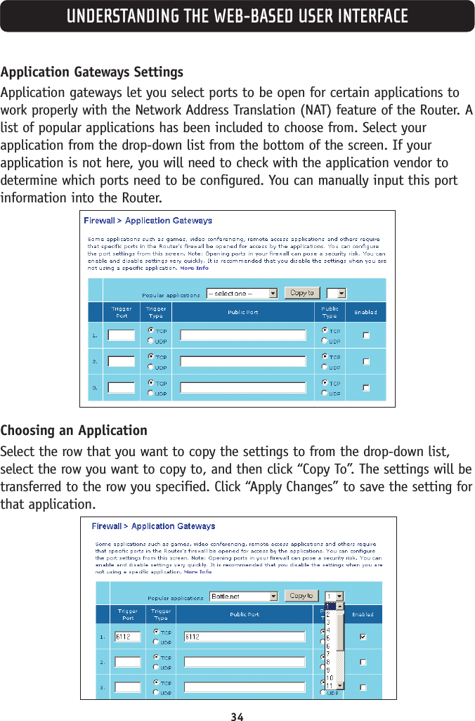
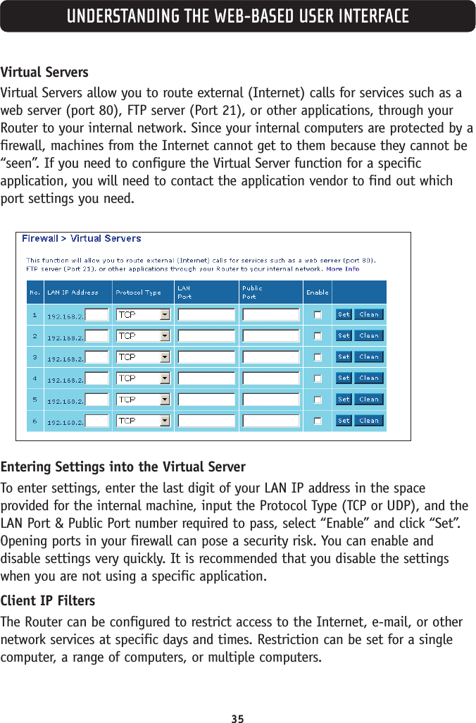
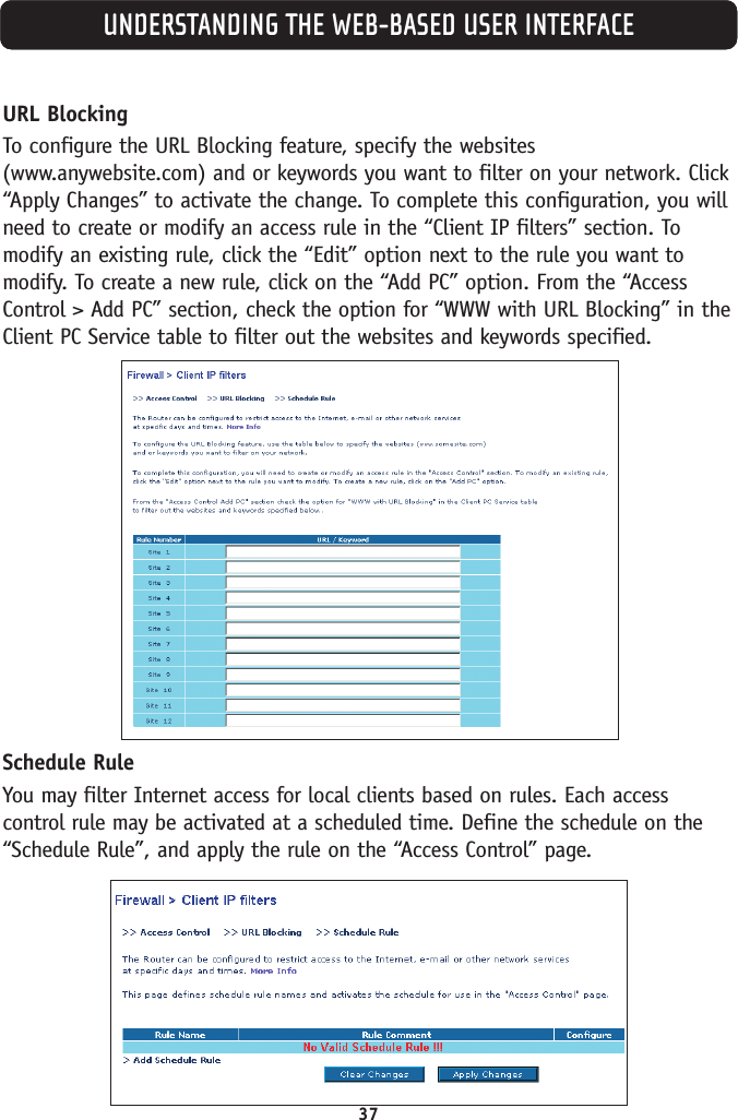
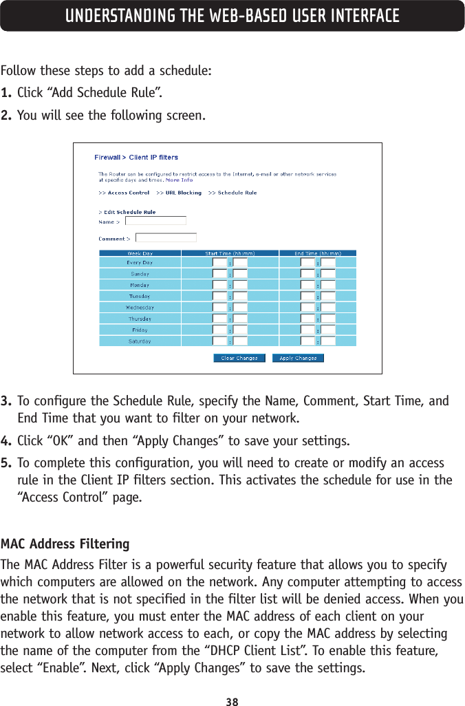
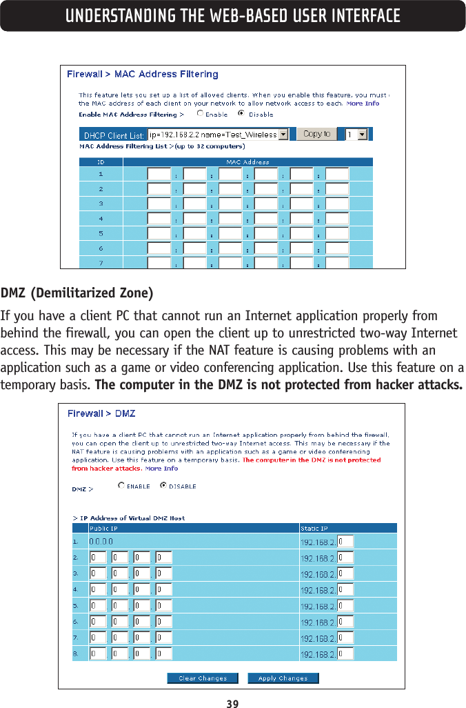
Belkin F5D7630-4A ADSL Modem with Built-in Wireless Router User Manual 23MS293 F5D7630 4A man
Belkin International, Inc. ADSL Modem with Built-in Wireless Router 23MS293 F5D7630 4A man
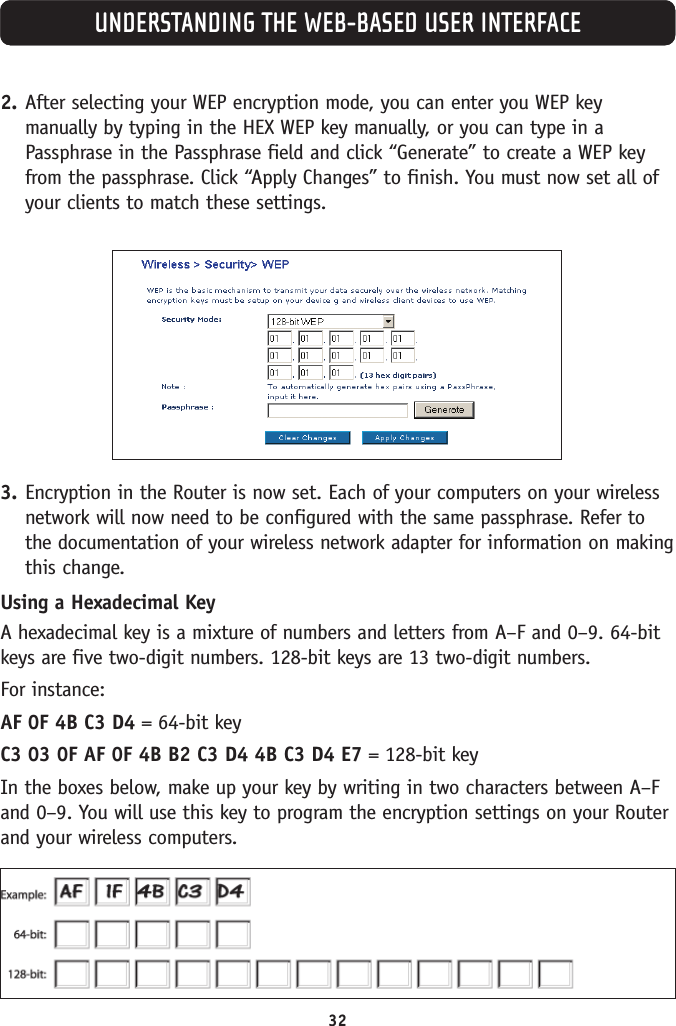
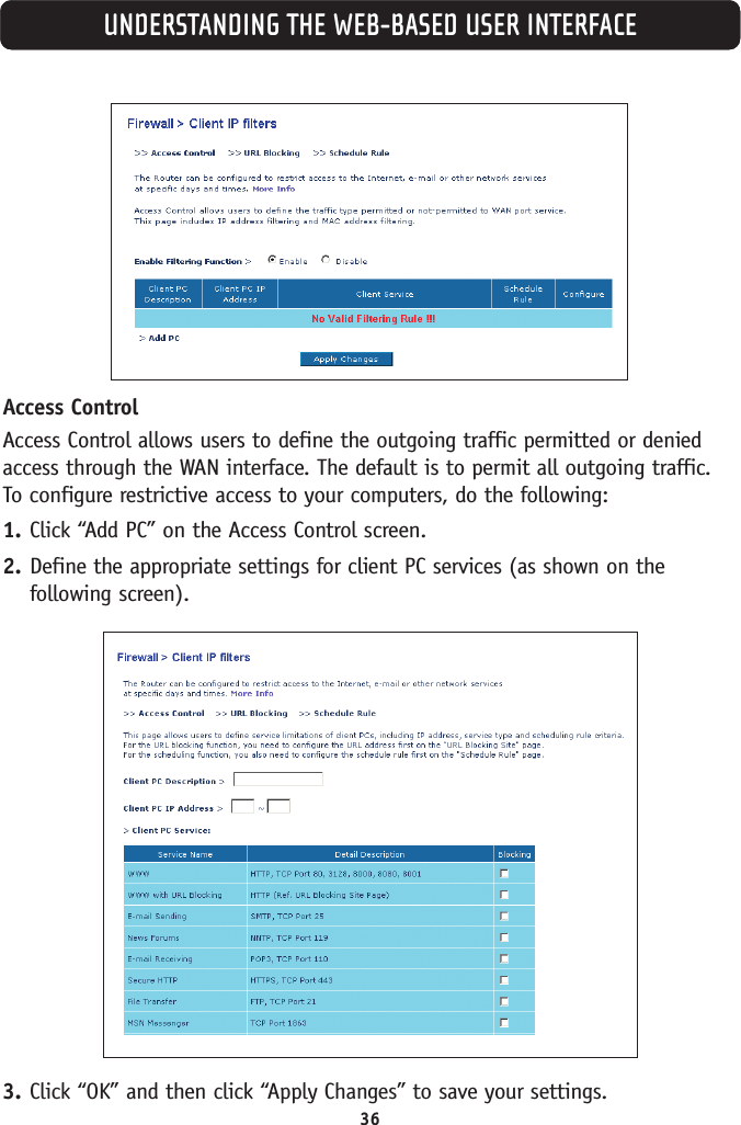
Belkin >
Contents
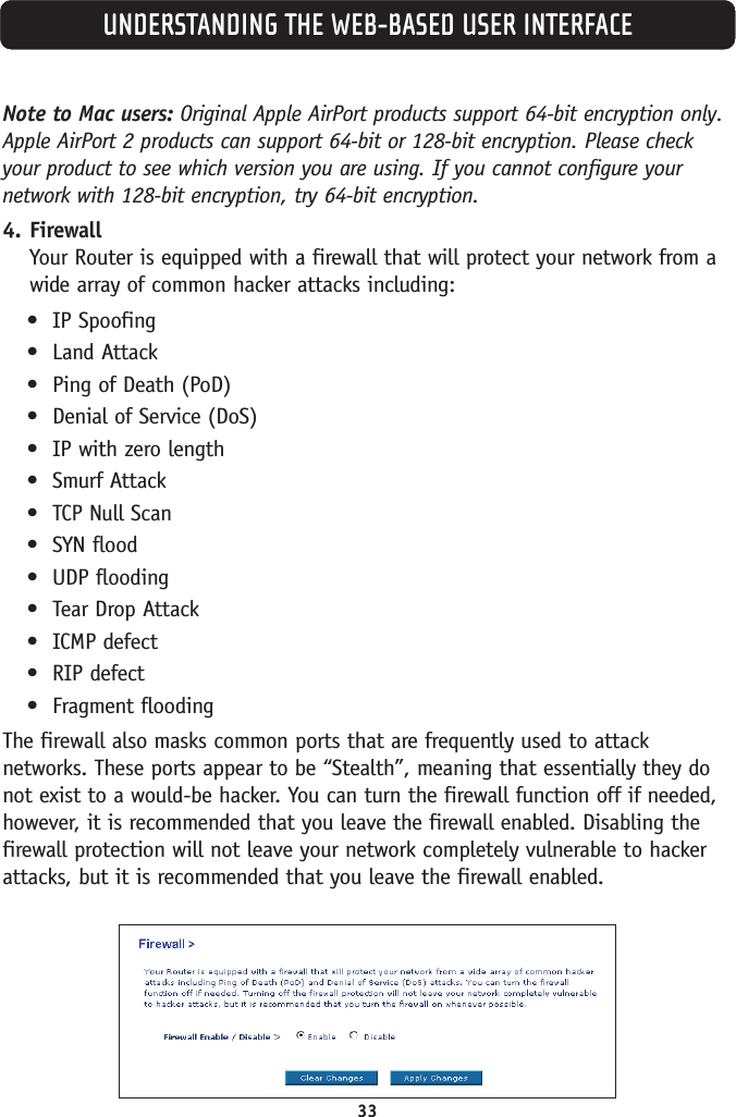
- 1. User Manual Part 1
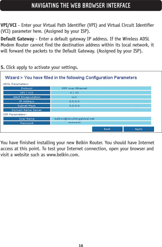
- 2. User Manual Part 2
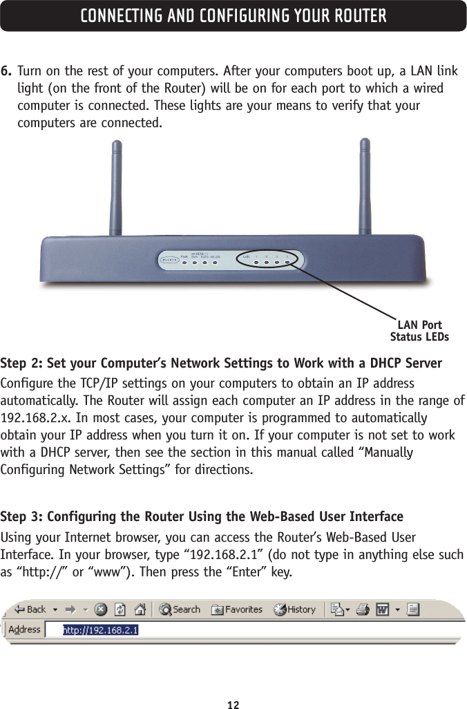
User Manual Part 1