Belkin F5D7630-4A ADSL Modem with Built-in Wireless Router User Manual 23MS293 F5D7630 4A man
Belkin International, Inc. ADSL Modem with Built-in Wireless Router 23MS293 F5D7630 4A man
Belkin >
Contents
- 1. User Manual Part 1
- 2. User Manual Part 2
User Manual Part 1
User Manual
F5D7630-4A
F5D7630-4B
Network your computers with this one-box
solution that connects and shares your ADSL
Internet access
ADSL Modem with
Built-In 802.11g
Wireless Router

TABLE OF CONTENTS
Introduction . . . . . . . . . . . . . . . . . . . . . . . . . . . . . . . . . . . . . . . . . . . . 1
Overview . . . . . . . . . . . . . . . . . . . . . . . . . . . . . . . . . . . . . . . . . . . . . . 1
Key Features . . . . . . . . . . . . . . . . . . . . . . . . . . . . . . . . . . . . . . . . .1
Package Contents . . . . . . . . . . . . . . . . . . . . . . . . . . . . . . . . . . . . . . 3
System Requirements . . . . . . . . . . . . . . . . . . . . . . . . . . . . . . . . . . . 3
Knowing your Router . . . . . . . . . . . . . . . . . . . . . . . . . . . . . . . . . . . . . . 4
Placement of your Router . . . . . . . . . . . . . . . . . . . . . . . . . . . . . . . . . . . 7
Connecting and Configuring your Router . . . . . . . . . . . . . . . . . . . . . . . . . . 8
Navigating the Web Browser Interface . . . . . . . . . . . . . . . . . . . . . . . . . . 14
Understanding the Web-Based User Interface . . . . . . . . . . . . . . . . . . . . . . 17
Manually Configuring Network Settings . . . . . . . . . . . . . . . . . . . . . . . . . . 48
Glossary . . . . . . . . . . . . . . . . . . . . . . . . . . . . . . . . . . . . . . . . . . . . . . 55
Troubleshooting . . . . . . . . . . . . . . . . . . . . . . . . . . . . . . . . . . . . . . . . . 61
Information . . . . . . . . . . . . . . . . . . . . . . . . . . . . . . . . . . . . . . . . . . . . 63

1
INTRODUCTION
Thank you for purchasing the ADSL Modem with Built-In 802.11g Wireless Router
(the Router). In minutes, you will be able to share your Internet connection and
network your computers. The following is a list of features that make your new
Router an ideal solution for your home or small office network.
OVERVIEW
Key Features
Integrated 802.11g Wireless Access Point
802.11g is an exciting new wireless technology that provides up to 54Mbps
(nearly five times faster than 802.11b) data rates.
Works with Both PCs and Mac® Computers
The Wireless ADSL Modem Router supports a variety of networking environments
including Mac OS® 8.x, 9.x, X v10.x, AppleTalk®, Linux®, Windows® 95, 98, Me,
NT®, 2000, and XP, and others. All that is needed is an Internet browser and a
network adapter that supports TCP/IP (the standard language of the Internet).
Front-Panel LED Display
Lighted LEDs on the front of the Router indicate which functions are in
operation. You’ll know at-a-glance whether your Router is connected to the
Internet. This feature eliminates the need for advanced software and status-
monitoring procedures.
Web-Based User Interface
You can set up the Router’s functions easily through your web browser, without
having to install additional software onto the computer. There are no disks to
install or keep track of and, best of all, you can make changes and perform setup
functions from any computer on the network quickly and easily.
NAT IP Address Sharing
Your Router employs Network Address Translation (NAT) to share the single IP
address assigned to you by your Internet Service Provider while saving the cost
of adding additional IP addresses to your Internet service account.

INTRODUCTION
2
SPI Firewall
Your Router is equipped with a firewall that will protect your network from a wide
array of common hacker attacks including IP Spoofing, Land Attack, Ping of
Death (PoD), Denial of Service (DoS), IP with zero length, Smurf Attack, TCP Null
Scan, SYN flood, UDP flooding, Tear Drop Attack, ICMP defect, RIP defect, and
fragment flooding.
Integrated 10/100 4-Port Switch
The Router has a built-in, four-port network switch to allow your wired
computers to share printers, data and MP3 files, digital photos, and much more.
The switch features automatic detection so it will adjust to the speed of
connected devices. The switch will transfer data between computers and the
Internet simultaneously without interrupting or consuming resources.
Built-In Dynamic Host Configuration Protocol (DHCP) on-board makes for the
easiest possible connection of a network. The DHCP server will assign IP
addresses to each computer automatically so there is no need for a complicated
networking setup.
MAC Address Filtering
For added security, you can set up a list of MAC addresses (unique client
identifiers) that are allowed access to your network. Every computer has its own
MAC address. Simply enter these MAC addresses into a list using the web-based
user interface and you can control access to your network.
Applications and Advantages
•Economically connect multiple computers to a single Internet connection
•SOHO (Small Office/Home Office) networking needs
Provides the easy and quick small network installation SOHO users need

INTRODUCTION
Package Contents
•ADSL Modem with Built-In 802.11g Wireless Router
•RJ45 Ethernet Networking Cable (for connecting the Router to the computer)
•RJ11 Phone Line Cord (for connecting the Router to the ADSL line)
•ADSL In-Line Filter
•Power Supply
•Quick Installation Guide
•User Manual CD-ROM
•Registration Card
System Requirements
•ADSL connection
•At least one computer with an installed network interface adapter
•TCP/IP networking protocol installed on each computer
•CAT5 networking cable (or better)
•Microsoft® Internet Explorer 4.0 or later, or Netscape® 4.0 or later
3
KNOWING YOUR ROUTER
4
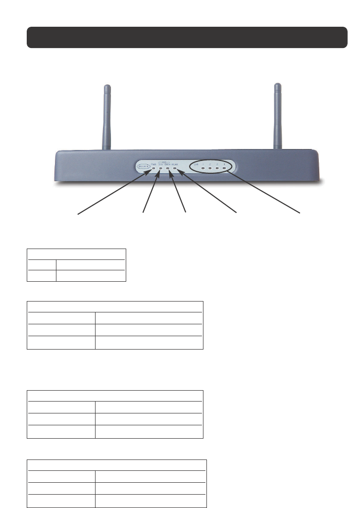
Front Panel
This LED lights in GREEN to indicate that your Modem Router is connected properly to the
ADSL line.
Wireless
Network LED LAN Port
Status LEDs
ADSL – SYN
Status LED
Power LED
(PWR) ADSL – Data LED
Power LED (PWR)
OFF Router is OFF
Green Router is ready
ADSL – SYN Status LED
OFF No ADSL connection
Solid Green ADSL connection is ready
Blinking Green Negotiating connection
ADSL – Data LED
OFF No WAN connection
Green WAN connection is ready
Blinking Indicates WAN activity
Wireless Network LED
OFF Wireless network is OFF
Green Wireless network is ready
Blinking Indicates wireless activity
KNOWING YOUR ROUTER
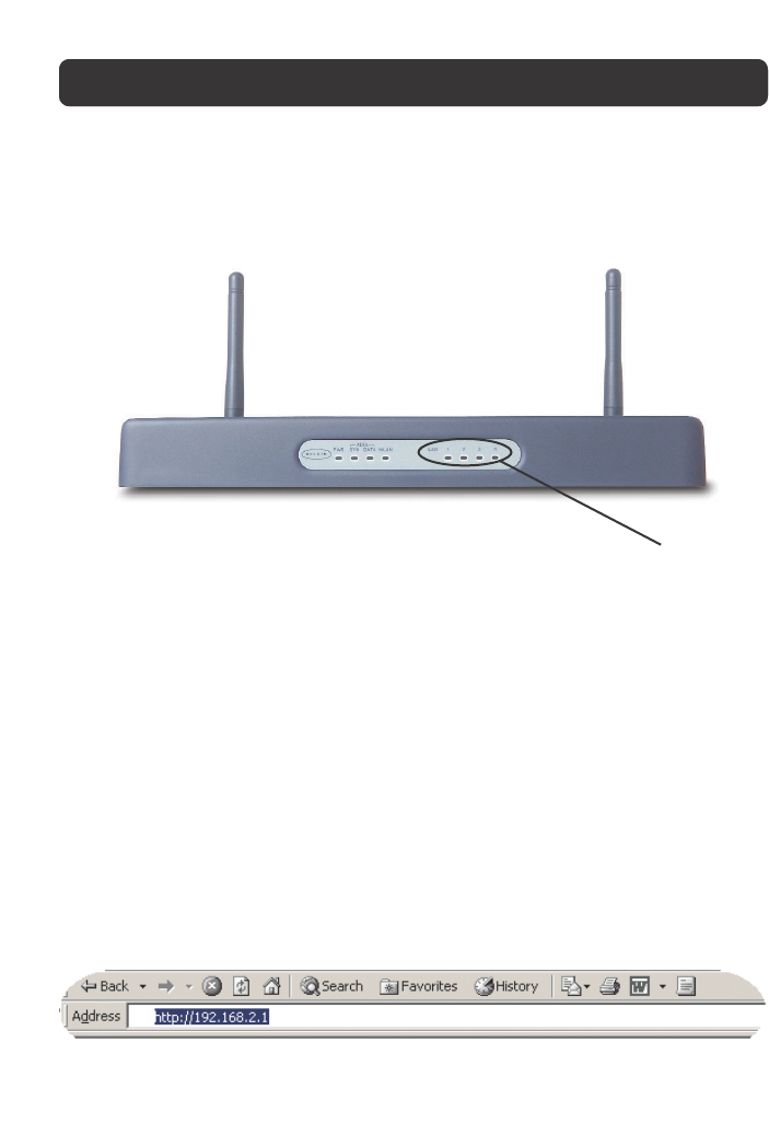
These LEDs are labeled 1–4 and correspond to the numbered ports on the rear of
the Router. When a computer is properly connected to one of the LAN ports on
the rear of the Router, the LED will light. When information is being sent over
the port, the LED blinks rapidly.
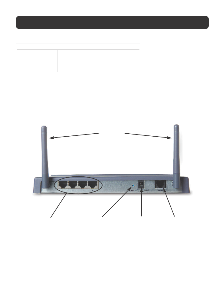
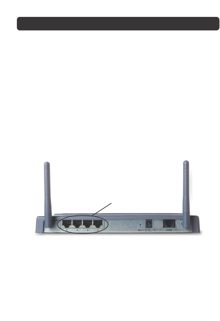
Rear Panel
LAN Ports
The LAN ports are RJ45, 10/100 auto-negotiation. The ports are labeled 1
through 4. These ports correspond to the numbered LEDs on the front of the
Router. Connect your LAN computers or any networking devices to one of
these ports.
Reset Button
The “Reset” button is used in rare cases when the Router may function
improperly. Resetting the Router will restore the Router’s normal operation while
5
LAN Port-Status LEDs
OFF No device is linked to the port
Solid Orange 10/100Base-Tx device connected
Blinking Orange Port activity
Power Jack ADSL PortLAN Ports Reset Button
Antennas

KNOWING YOUR ROUTER
6
maintaining the programmed settings. You can also restore the factory default
settings by using the Reset button. Use the restore option in instances where you
may have forgotten your custom password.
a. Resetting the Router
Push and release the Reset button. When the Power/Ready light becomes solid
again, the reset is complete.
b. Restoring the Factory Defaults
Press and hold the Reset button for 10 seconds then release it. When the
Power/Ready light becomes solid again, the restore is complete.
Power Jack
Connect the included 12V DC power supply to this inlet. Using the wrong type of
power adapter may cause damage to your Router.
ADSL Port
This port is for connection to your ADSL line. Connect your ADSL line to this port.

PLACEMENT OF YOUR ROUTER
7
Proper placement of your Router is important to ensure the best performance of
your wireless network. Typically, indoors your Wireless Router can provide a
circular coverage area of 250 feet or more. However, different types of
construction materials and other obstructions in a building can greatly affect the
wireless signal and decrease the range. Whenever possible, your Router should be
placed as close as possible to the center of the area that you want to cover. In
multi-story homes, place the Router on a floor that is as close to the center of
the home as possible; this may mean placing the Router on an upper floor.
Use care when choosing the location of your Router.
•Be aware of appliances or large objects such as a refrigerator or washer/dryer
unit that may be on the opposite side of a wall from where you decide to
place your Router.
•Place the Router on top of a desk and away from metal cabinets and
computer cases.
•Do not place objects or components on top of the Router.
•Make sure that both antennas are pointing UP at all times.
•Metallic-based UV window tint can affect wireless performance. Do not place
the Router next to a tinted window.
We realize that in the real world, it may not be possible to place your Router in
the center of your coverage area. In cases where you may experience difficulty
covering the entire area you want, try placing the Router as high as possible.
Wireless devices work best in a line-of-sight situation where there are no
obstacles between the wireless computer and the Router. The Router may also be
mounted to a wall with the antennas facing UP. There are other options for
expanding your wireless coverage area. Visit www. belkin.com/networking for
solutions.
The wireless signal can be affected by many things including neighboring wireless
networks, microwave ovens in operation, and 2.4GHz cordless phones. While
these things can affect the network performance, your wireless network typically
will work fine under most conditions where these devices exist.

CONNECTING AND CONFIGURING YOUR ROUTER
8
ISP Settings
Please collect the following information from your ISP before setting up the
Wireless ADSL Modem Router.
For PPPoE and PPPoA users
•VCI and VPI number
•An ISP account user name and password
For fixed IP users
•IP address and subnet mask
•IP address for your ISP’s Gateway Server and Domain Name Server
Connect the System
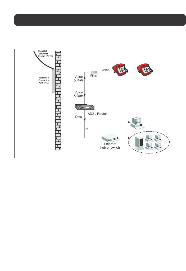
Connect the ADSL Line
Run standard telephone cable from the wall jack providing ADSL service to the
ADSL port on your Wireless ADSL Modem Router. When inserting an ADSL RJ11
plug, be sure the tab on the plug clicks into position to ensure that it is properly
seated. If you are using splitterless ADSL service, add low-pass filters between
the ADSL wall jack and your telephones. (These filters pass voice signals through
but filter data signals out.)
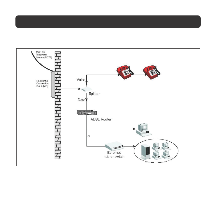
Phone Line Configuration
Installing a Full-Rate Connection
If you are using a full-rate (G.dmt) connection, your service provider will attach
the ADSL line to a data/voice splitter. In this case, you can connect your phones
and computer directly to the splitter as shown on the next page.
CONNECTING AND CONFIGURING YOUR ROUTER
9
Installing with a Splitter
Installing a Splitterless Connection
If you are using a splitterless (G.lite) connection, then your service provider will
attach the outside ADSL line directly to your phone system. In this case, you
can connect your phones and computer directly to the incoming ADSL line, but
you will have to add low-pass filters to your phones as shown on the next page.
CONNECTING AND CONFIGURING YOUR ROUTER
10
Installing without a Splitter
Attach to your Network Using Ethernet Cabling
The four LAN ports on the ADSL Modem Router auto-negotiate the connection
speed to 10Mbps Ethernet or 100Mbps Fast Ethernet, as well as the transmission
mode to half duplex or full duplex.
Configuring the Router
The Belkin Wireless ADSL Modem Router is equipped with a Web-Based Interface
that you can use to set up the Router. From the Web-Based Interface, you can
perform the following tasks:
•View the Router’s current settings and status.
•Configure the Router to connect to your ISP with the settings that they
provided you.
•Change the current network settings such as the internal IP address, the IP
address pool, DHCP settings, and more.
11
CONNECTING AND CONFIGURING YOUR ROUTER
•Set the Router’s firewall to work with specific applications (port forwarding).
•Set up security features such as client restrictions and MAC address filtering.
•Enable the DMZ feature for a single computer on your network.
•Change the Router’s internal password.
•Reset the Router.
•Reset the Router’s default settings.
•Update the Router’s firmware.
Step 1: Installing the Hardware
1. Power down your equipment.
2. Connect each PC to one of the ports on the rear of the Router labeled LAN by
using a RJ45 networking cable.
3. Connect the telephone cable from the wall jack providing ADSL service to the
ADSL port on your Router.
Note: When inserting an ADSL RJ11 plug, be sure the tab on the plug clicks into
position to ensure that it is properly seated.
4. Connect the power adapter to the Router.
5. After the Router is turned on, the Router’s Power light should be on.
LAN Ports
12
CONNECTING AND CONFIGURING YOUR ROUTER
6. Turn on the rest of your computers. After your computers boot up, a LAN link
light (on the front of the Router) will be on for each port to which a wired
computer is connected. These lights are your means to verify that your
computers are connected.
Step 2: Set your Computer’s Network Settings to Work with a DHCP Server
Configure the TCP/IP settings on your computers to obtain an IP address
automatically. The Router will assign each computer an IP address in the range of
192.168.2.x. In most cases, your computer is programmed to automatically
obtain your IP address when you turn it on. If your computer is not set to work
with a DHCP server, then see the section in this manual called “Manually
Configuring Network Settings” for directions.
Step 3: Configuring the Router Using the Web-Based User Interface
Using your Internet browser, you can access the Router’s Web-Based User
Interface. In your browser, type “192.168.2.1” (do not type in anything else such
as “http://” or “www”). Then press the “Enter” key.
LAN Port
Status LEDs
13
CONNECTING AND CONFIGURING YOUR ROUTER
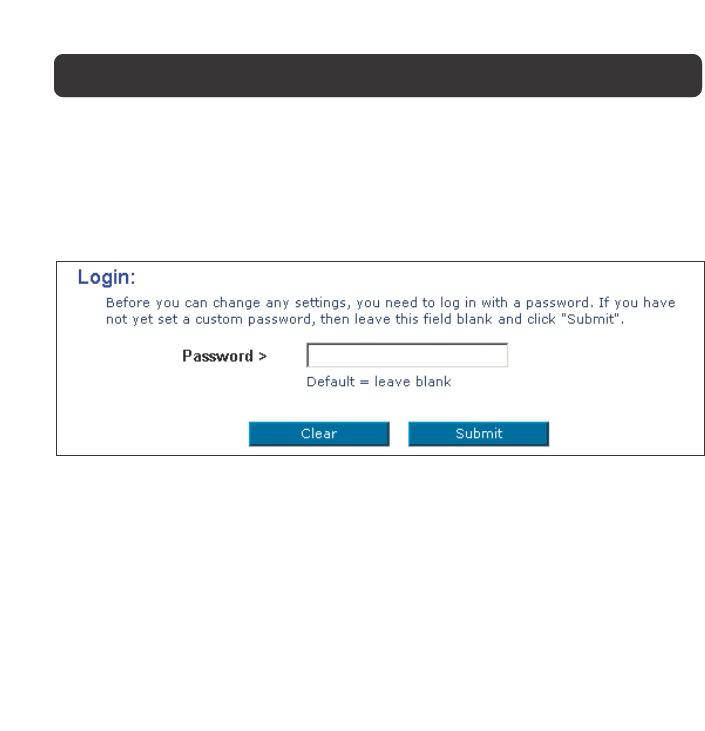
Logging into the Router
To configure the Router’s settings, you have to log in. The Router is supplied
with no password entered. In the login screen, leave the password blank and
click the “Submit” button to log in.
Logging out of the Router
One computer at a time can log into the Router for the purposes of making
changes to the settings of the Router. Once a user has logged in to make
changes, there are two ways that the computer can be logged out. Clicking the
“Logout” button will log the computer out. The second method is automatic. The
login will time-out after a specified period of time. The default login time-out is
10 minutes. This can be changed from 1 to 99 minutes. For more information,
see the section in this manual titled “Changing the Login Time-out Setting”.
14
NAVIGATING THE WEB BROWSER INTERFACE
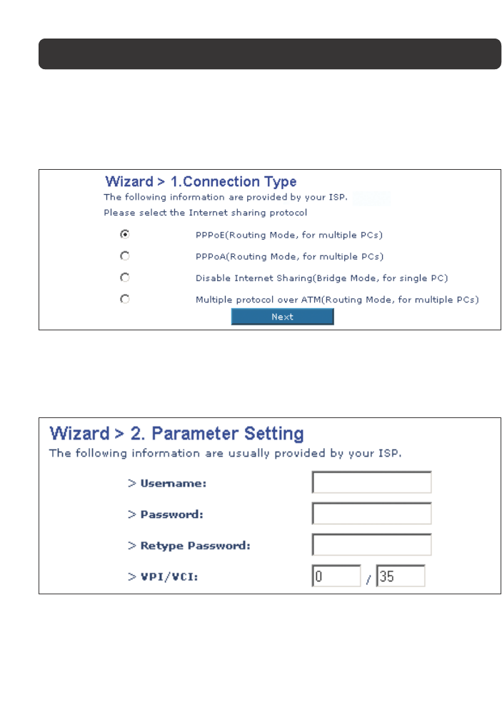
Setup Wizard
1. Internet Sharing
Select the connection type you are using. This information is provided by your ISP.
2. Setting your ISP Connection Type to PPPoE or PPPoA
Enter the PPPoE (Point-to-Point Protocol over Ethernet) or PPPoA information in
the provided spaces, and click “Next”. Click “Apply” to activate your settings. This
information is provided by your ISP.
User Name - Enter the ISP assigned user name. (Assigned by your ISP).
Password - Enter your password. (Assigned by your ISP).
Retype Password - Confirm the password. (Assigned by your ISP).
VPI/VCI - Enter your Virtual Path Identifier (VPI) and Virtual Circuit Identifier
(VCI) parameter here. (Assigned by your ISP).
15
NAVIGATING THE WEB BROWSER INTERFACE
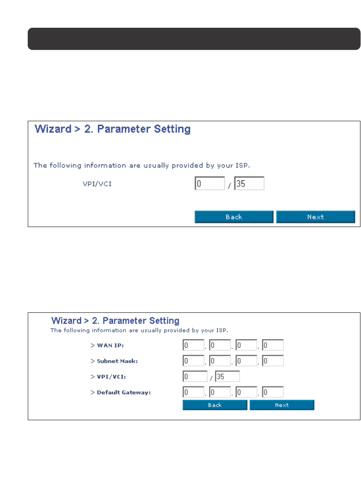
3. Setting your Connection Type to Disable Internet Sharing
Enter VPI/VCI value in the provided spaces, and then click “Next”. Click “Apply”
to activate your settings.
VPI/VCI - Enter your Virtual Path Identifier (VPI) and Virtual Circuit Identifier
(VCI) parameter here. (Assigned by your ISP).
4. Setting your Connection Type to Multiple Protocol over ATM Mode
Enter ATM (Asynchronous Transfer Mode) information in the provided spaces, and
click “Next”. Click “Apply” to activate your settings.
WAN IP - Enter an IP address for the Wireless ADSL Modem Router WAN interface.
(Assigned by your ISP).
Subnet Mask - Enter a subnet mask. (Assigned by your ISP).
16
VPI/VCI - Enter your Virtual Path Identifier (VPI) and Virtual Circuit Identifier
(VCI) parameter here. (Assigned by your ISP).
Default Gateway - Enter a default gateway IP address. If the Wireless ADSL
Modem Router cannot find the destination address within its local network, it
will forward the packets to the Default Gateway. (Assigned by your ISP).
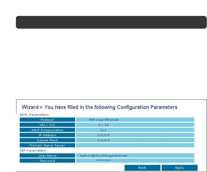
5. Click apply to activate your settings.
You have finished installing your new Belkin Router. You should have Internet
access at this point. To test your Internet connection, open your browser and
visit a website such as www.belkin.com.
NAVIGATING THE WEB BROWSER INTERFACE
17
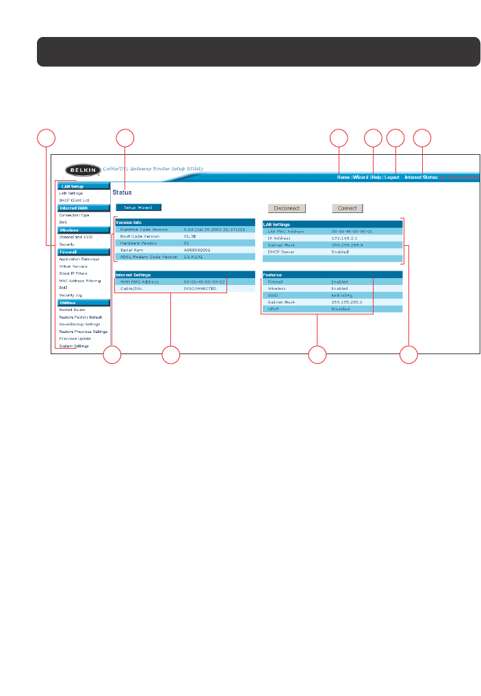
UNDERSTANDING THE WEB-BASED USER INTERFACE
The home page shows you a quick view of the Router’s status and settings. All
advanced setup pages can be reached from this page.
1. Quick-Navigation Links
You can go directly to any of the Router’s UI pages by clicking directly on
these links. The links are divided into logical categories and grouped by tabs
to make finding a particular setting easier to find. Clicking on the header of
each tab will show you a short description of the tab’s function.
2. Home Button
The Home button is available in every page of the UI. Pressing this button
will take you back to the home page.
3. Internet Status Indicator
This indicator is visible in all pages of the Router, indicating the connection
status of the Router. When the indicator says “connection OK” in GREEN, the
Router is connected to the Internet. When the Router is not connected to
the Internet, the indicator will read “no connection” in RED. The indicator is
automatically updated when you make changes to the settings of the Router.
4. Login/Logout Button
This button enables you to log in and out of the Router with the press of
one button. When you are logged into the Router, this button will change to
read “Logout”. Logging into the Router will take you to a separate login
110 2543
98 7 6

18
UNDERSTANDING THE WEB-BASED USER INTERFACE
page where you will need to enter a password. When you are logged into the
Router, you can make changes to the settings. When you are finished making
changes, you can log out of the Router by clicking the “Logout” button. For
more information about logging into the Router, see the section called
“Logging into the Router”.
5. Help Button
The “Help” button gives you access to the Router’s help pages. Help is also
available on many pages by clicking “more info” next to certain sections of
each page.
6. LAN Settings
Shows you the settings of the Local Area Network (LAN) side of the Router.
Changes can be made to the settings by clicking the “LAN” Quick Navigation
link on the left side of the screen.
7. Features
Shows the status of the Router’s NAT, firewall, and wireless features. Changes
can be made to the settings by clicking on any one of the links or by clicking
the “Quick Navigation” links on the left side of the screen.
8. Internet Settings
Shows the settings of the Internet/WAN side of the Router that connects to
the Internet. Changes to any of these settings can be made by clicking on
the “Internet/WAN” Quick Navigation link on the left side of the screen.
9. Version Info
Shows the firmware version, boot-code version, hardware version, and serial
number of the Router.
10.Page Name
The page you are on can be identified by this name. This manual will
sometimes refer to pages by name. For instance, “LAN > LAN Settings” refers
to the “LAN Settings” page.
19
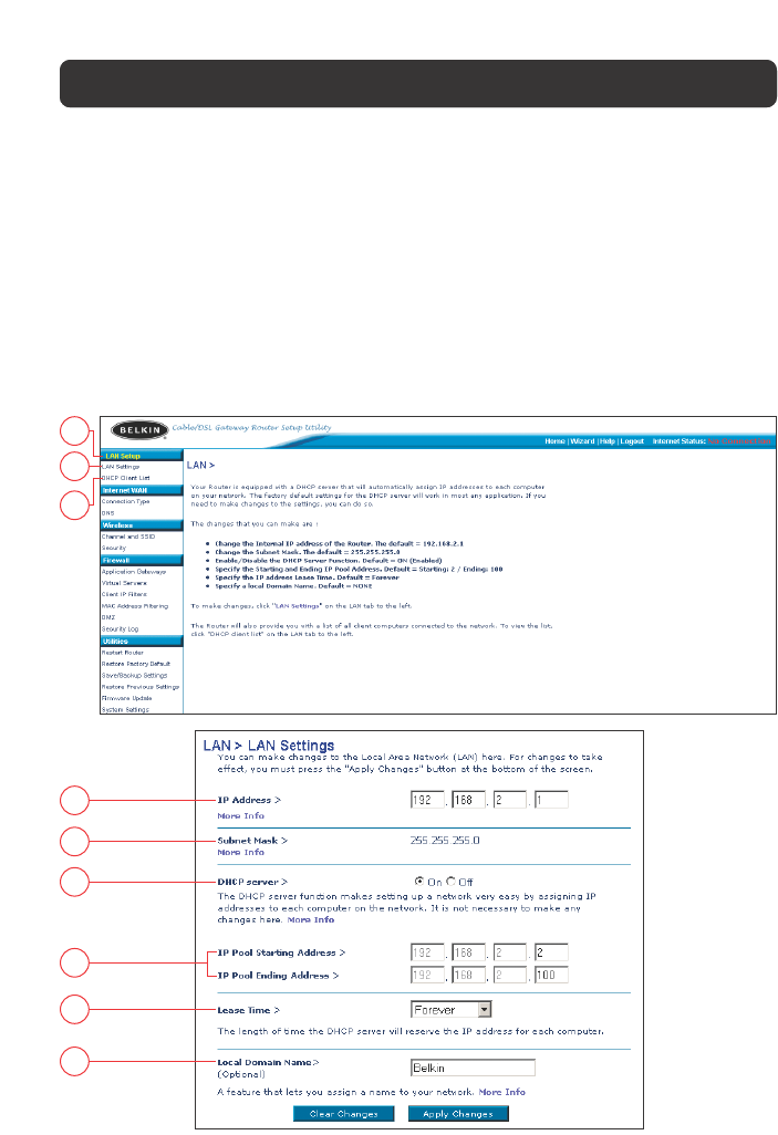
Changing LAN Settings
All settings for the internal LAN setup of the Router can be viewed and changed here.
1. LAN Settings
Clicking on the header of the LAN tab (A) will take you to the LAN tab’s header
page. A quick description of the functions can be found here. To view the settings
or make changes to any of the LAN settings, click on “LAN Settings” (B) or to
view the list of connected computers, click on “DHCP client list” (C).
A
B
C
1
2
3
4
5
6
UNDERSTANDING THE WEB-BASED USER INTERFACE

20
UNDERSTANDING THE WEB-BASED USER INTERFACE
1. IP Address
The “IP address” is the internal IP address of the Router. The default IP
address is “192.168.2.1”. To access the setup interface, type this IP address
into the address bar of your browser. This address can be changed if needed.
To change the IP address, type in the new IP address and click “Apply
Changes”. The IP address you choose should be a non-routable IP. Examples of
a non-routable IP are:
192.168.x.x (where x is anything between 0 and 255)
10.x.x.x (where x is anything between 0 and 255)
2. Subnet Mask
There is no need to change the subnet mask. This is a unique, advanced
feature of your Belkin Router.
3. DHCP Server
The DHCP server function makes setting up a network very easy by assigning
IP addresses to each computer on the network automatically. The default
setting is “On”. The DHCP server can be turned OFF if necessary, however, in
order to do so you must manually set a static IP address for each computer on
your network. To turn off the DHCP server, select “Off” and click “Apply
Changes”.
4. IP Pool
The IP Pool is the range of IP addresses set aside for dynamic assignment to
the computers on your network. The default is 2–100 (99 computers). If you
want to change this number, you can do so by entering a new starting and
ending IP address and clicking on “Apply Changes”. The DHCP server can assign
100 IP addresses automatically. This means that you cannot specify an IP
address pool larger than 100 computers. For example, starting at 50 means
you have to end at 150 or lower so as not to exceed the 100-client limit. The
starting IP address must be lower in number than the ending IP address.
5. Lease Time
Lease time is the length of time the DHCP server will reserve the IP address
for each computer. We recommend that you leave the lease time set to
“Forever”. The default setting is “Forever”, meaning that any time a computer
is assigned an IP address by the DHCP server, the IP address will not change
for that particular computer. Setting lease times for shorter intervals, such as
21
UNDERSTANDING THE WEB-BASED USER INTERFACE
one day or one hour, frees IP addresses after the specified period of time. This
also means that a particular computer’s IP address may change over time. If
you have set any of the other advanced features of the Router, such as DMZ or
client IP filters, these are dependent on the IP address. For this reason, you
will not want the IP address to change.
6. Local Domain Name
The default setting is “Belkin”. You can set a local domain name (network
name) for your network. There is no need to change this setting unless you
have a specific advanced need to do so. You can name the network anything
you want such as “MY NETWORK”.
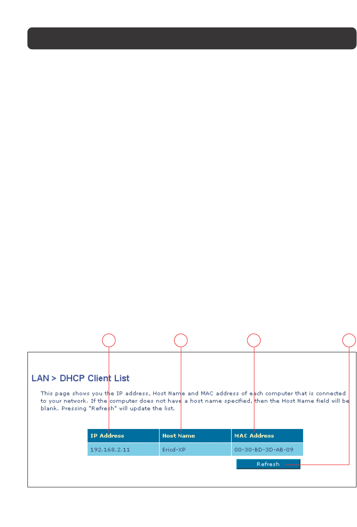
DHCP Client List
You can view a list of the computers (known as clients), which are connected to
your network. You are able to view the IP address (1) of the computer, the host
name (2) (if the computer has been assigned one), and the MAC address (3) of
the computer’s network interface card (NIC). Pressing the “Refresh” (4) button
will update the list. If there have been any changes, the list will be updated.
12 3 4
22
UNDERSTANDING THE WEB-BASED USER INTERFACE
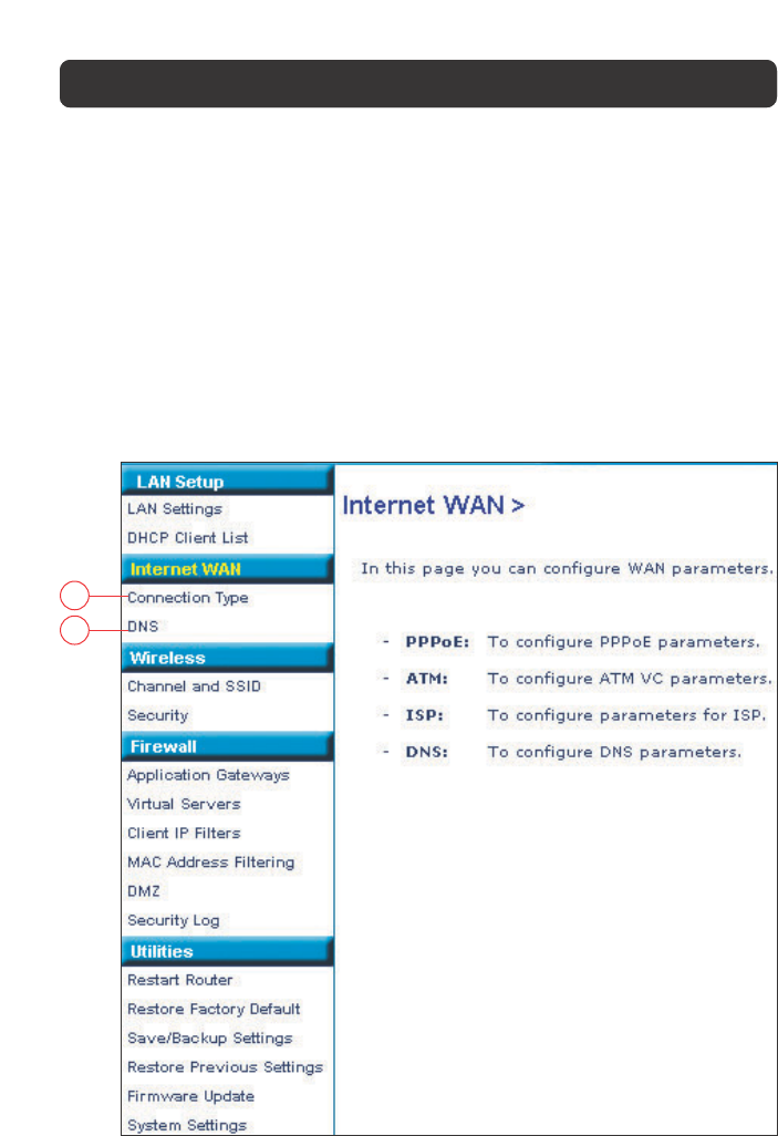
2. Internet WAN
The “Internet WAN” tab is where you will set up your Router to connect to your
Internet Service Provider. The Router is capable of connecting to virtually any
ADSL Service Provider’s system provided you have correctly configured the
Router’s settings for your ISP’s connection type. Your connection settings are
provided to you by your ISP. To configure the Router with the settings that your
ISP gave you, click “Connection Type” (A) on the left side of the screen. Select
the connection type you use. If your ISP gave you DNS settings, clicking “DNS”
(B) allows you to enter DNS address entries for ISPs that require specific settings.
When you have finished making settings, the “Internet Status” indicator will read
“Connection OK” if your Router is set up properly.
A
B
23
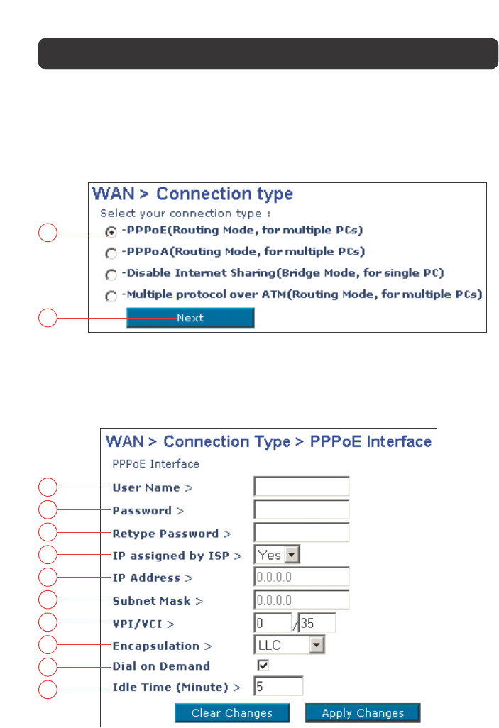
Connection Type
From the Connection Type page, you can select the type of connection you use.
Select the type of connection you use by clicking the radio button (1) next to
your connection type and then clicking “Next” (2).
1
2
Setting your ISP Connection Type to PPPoE or PPPoA
Enter the PPPoE (Point-to-Point Protocol over Ethernet) or PPPoA information in
the provided spaces, and click “Next”. Click “Apply” to activate your settings. This
information is provided by your ISP.
a
b
c
d
e
f
g
h
i
j
UNDERSTANDING THE WEB-BASED USER INTERFACE

UNDERSTANDING THE WEB-BASED USER INTERFACE
24
a. Username - Enter the ISP assigned user name. (Assigned by your ISP).
b. Password - Enter your password. (Assigned by your ISP).
c. Retype Password - Confirm the password. (Assigned by your ISP).
d. IP assigned by ISP - Select “Yes” for automatic IP assignment from your ISP.
Select “No” only if your ISP assigns you a fixed IP address.
e. IP address - If you are using a fixed IP address, enter the fixed IP address
supplied by your ISP.
f. Subnet Mask - If you are using a fixed IP address, enter the subnet mask
supplied by your ISP.
g. VPI/VCI - Enter your Virtual Path Identifier (VPI) and Virtual Circuit Identifier
(VCI) parameter here. (Assigned by your ISP).
h. Encapsulation - Select your encapsulation type (supplied by your ISP) to
specify how to handle multiple protocols at the ATM transport layer.
VC-MUX: Point-to-Point Protocol over ATM Virtual Circuit Multiplexer (null
encapsulation) allows only one protocol running per virtual circuit with
fewer overheads.
LLC: Point-to-Point Protocol over ATM Logical Link Control allows multiple
protocols running over one virtual circuit (more overhead).
i. Dial on Demand - By selecting “Dial on Demand” your Router will
automatically connect to the Internet when a user opens up a web browser.
j. Idle Time (Minutes) - Enter the maximum idle time for the Internet
connection. After this time has been exceeded, the connection will be
terminated.
25
UNDERSTANDING THE WEB-BASED USER INTERFACE
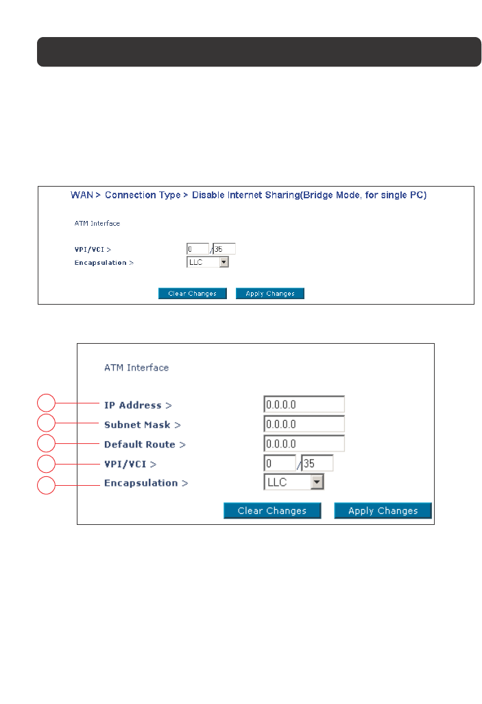
Setting your ISP Connection Type to Disable Internet Sharing
VPI/VCI - Enter your Virtual Path Identifier (VPI) and Virtual Circuit Identifier
(VCI) parameter here. (Assigned by your ISP).
Encapsulation - Select LLC or VC MUX. (Assigned by your ISP).
Setting your ISP Connection Type to Multiple Protocol over ATM
a
b
c
d
e
a. WAN IP - Enter an IP address for the Wireless ADSL Modem Router WAN
interface. (Assigned by your ISP).
b. Subnet Mask - Enter a subnet mask. (Assigned by your ISP).
c. Default Route - Enter a default gateway IP address. If the Wireless ADSL
Modem Router cannot find the destination address within its local network, it
will forward the packets to the Default Gateway. (Assigned by your ISP).
d. VPI/VCI - Enter your Virtual Path Identifier (VPI) and Virtual Circuit Identifier
(VCI) parameter here. (Assigned by your ISP).
e. Encapsulation - Select LLC or VC MUX. (Assigned by your ISP).
26
UNDERSTANDING THE WEB-BASED USER INTERFACE
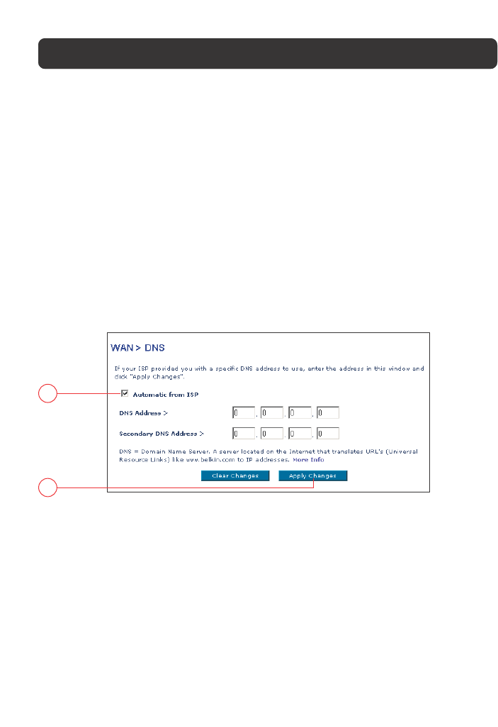
DNS (Domain Name Server) Settings
A “Domain Name Server” is a server located on the Internet that translates
Universal Resource Links (URLs) like “www.belkin.com” to IP addresses. Many
ISPs do not require you to enter this information into the Router. The “Automatic
from ISP” box (1) should be checked if your ISP did not give you a specific DNS
address. If you are using a static IP connection type, then you may need to enter
a specific DNS address and secondary DNS address for your connection to work
properly. If your connection type is dynamic or PPPoE, it is likely that you do not
have to enter a DNS address. Leave the “Automatic from ISP” box checked. To
enter the DNS address settings, uncheck the “Automatic from ISP” box and enter
your DNS entries in the spaces provided. Click “Apply Changes” (2) to save the
settings.
1
2
3. Wireless
The Wireless tab lets you make changes to the wireless network settings. From
this tab, you can make changes to the wireless network name (SSID), operating
channel, and encryption security settings.
Channel and SSID
Changing the Wireless Channel
There are a number of operating channels you can choose from. In the United
States, there are 11 channels. In the United Kingdom and most of Europe, there
are 13 channels. In a small number of other countries, there are other channel
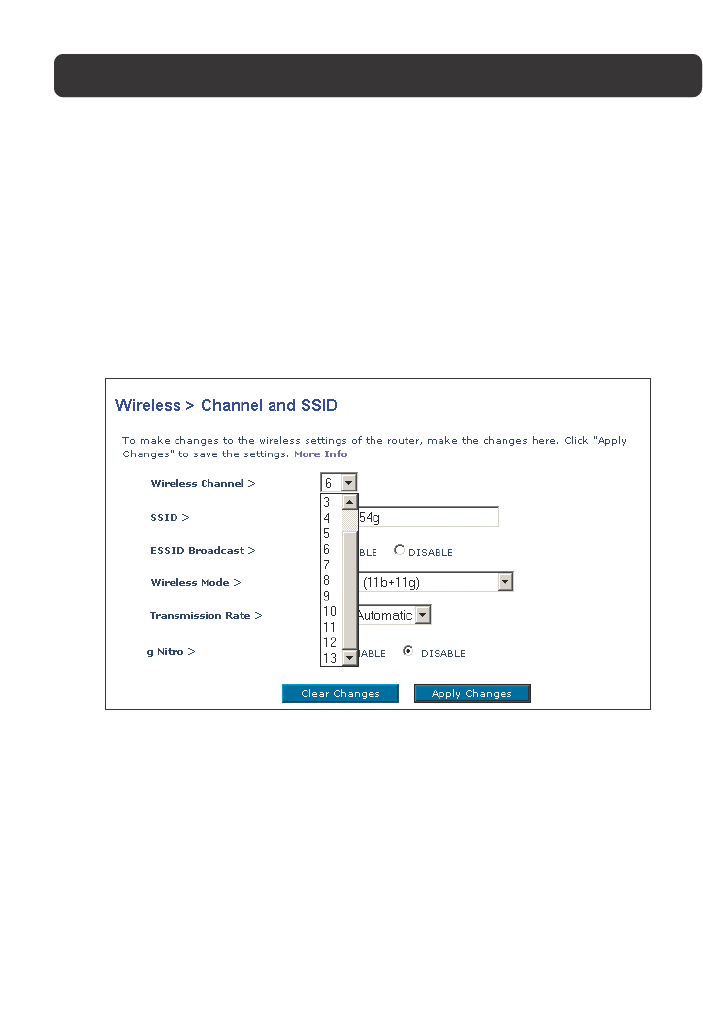
27
UNDERSTANDING THE WEB-BASED USER INTERFACE
requirements. Your Router is configured to operate on the proper channels for the
country you reside in. The default channel is 11 (unless you are in a country that
does not allow channel 11). The channel can be changed if needed. If there are
other wireless networks operating in your area, your network should be set to
operate on a channel that is different than the other wireless networks. For best
performance, use a channel that is at least five channels away from the other
wireless network. For instance, if another network is operating on channel 11,
then set your network to channel 6 or below. To change the channel, select the
channel from the drop-down list. Click “Apply Changes”. The change is immediate.
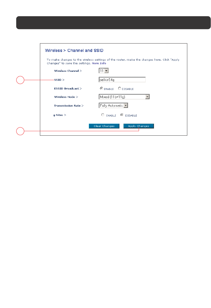
Changing the Wireless Network Name (SSID)
To identify your wireless network, a name called the SSID (Service Set Identifier)
is used. The default SSID of the Router is “belkin54g”. You can change this to
anything you want to or you can leave it unchanged. If there are other wireless
networks operating in your area, you will want to make sure that your SSID is
unique (does not match that of another wireless network in the area). To change
the SSID, type in the SSID that you want to use in the SSID field (1) and click
“Apply Changes” (2). The change is immediate. If you make a change to the
SSID, your wireless-equipped computers may also need to be reconfigured to
connect to your new network name. Refer to the documentation of your wireless
network adapter for information on making this change.
28
UNDERSTANDING THE WEB-BASED USER INTERFACE
1
2
Using the ESSID Broadcast Feature
For security purposes, you can choose not to broadcast your network’s SSID.
Doing so will keep your network name hidden from computers that are scanning
for the presence of wireless networks. To turn off the broadcast of the SSID,
select “DISABLE” and then click “Apply Changes”. The change is immediate. Each
computer now needs to be set to connect to your specific SSID; an SSID of “ANY”
will no longer be accepted. Refer to the documentation of your wireless network
adapter for information on making this change.
Note: This advanced feature should be employed by advanced users only.
Using the Wireless Mode Switch
Your Router can operate in three different wireless modes: “Mixed”, “11g Only”,
and “11b Only”. The different modes are explained next.
•Mixed - In this mode, the Router is compatible with 802.11b and 802.11g
wireless clients simultaneously. This mode is the factory default and ensures
full compatibility with Wi-Fi-compatible devices. Set the Router to Mixed mode
if you have a mix of 802.11b and 802.11g clients in your network. This is the
recommended setting for your router and should only be changed if you have
a specific reason to do so.

29
UNDERSTANDING THE WEB-BASED USER INTERFACE
•11g Only Mode - 11g Only mode is compatible with 802.11g clients only. This
mode can be useful only if you do not have any 802.11b clients that need
access to the network. To switch modes, select the desired mode from the
drop-down box next to “Wireless Mode” then click “Apply Changes”.
•11b Only Mode - It is not recommended you use this mode unless you have a
very specific reason to do so. This mode exists only to solve unique problems
that may occur with some 802.11b client adapters and is NOT necessary for
interoperability of 802.11g and 802.11b standards.
Note: Switching to 11b Only mode will decrease 802.11g performance
to 11Mbps.
g Nitro
Enabling “g Nitro” allows the Router to use Frame Bursting to get the maximum
throughput from the Router to 802.11g clients. g Nitro throughput is up to 50%
faster than any standard 802.11g equipment. g Nitro will work with 802.11g
clients that support g Nitro.
Encryption/Security
Changing the Wireless Security Settings
Your Router is equipped with the latest security standard called WPA (Wireless
Protected Access). It also supports the legacy security standard called WEP
(Wired Equivalent Privacy). By default, wireless security is disabled. To enable
security, you will need to determine which standard you want to use. To access
the Security settings, click “Security” on the Wireless tab.
Setting WPA Security
Note: To use WPA security, your clients must be upgraded to drivers and software
that support WPA. At the time this manual was published, a security patch from
Microsoft is available for free download. This patch works only with Windows XP.
You also need to download the latest driver for your Belkin 802.11g Wireless
Notebook Network Card from the Belkin support site. Other operating systems are
not supported at this time. Only Belkin 802.11g clients support WPA at this time.
There are two types of WPA security, WPA-PSK (no server) and WPA (with server).
WPA-PSK uses what is known as a pre-shared key as the security key. A
pre-shared key is basically a password that is between 8 and 40 characters long.
It can be a combination of letters, numbers, or characters. Each client uses the
same key to access the network. Typically, this is the mode that will be used in a
home environment.
WPA (with server) is a system where a radius server distributes the keys to the
clients automatically. This is typically found in a business environment.
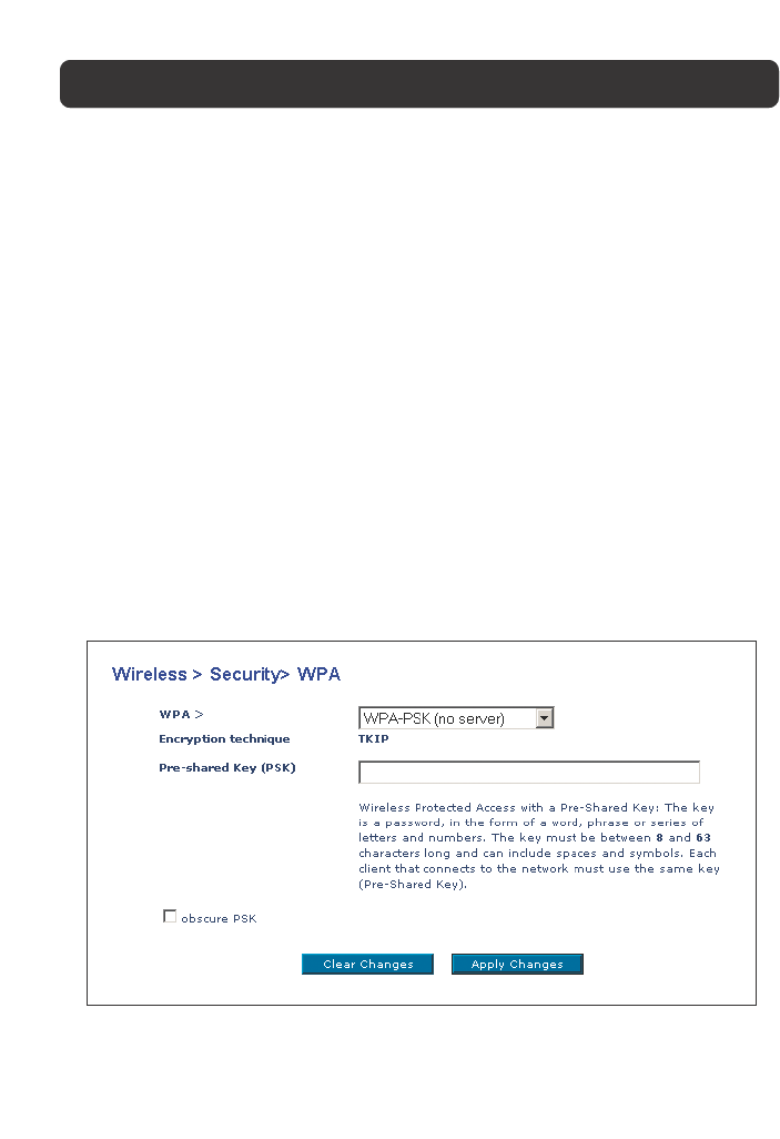
Setting WPA-PSK (no server)
1. From the Security Mode drop-down menu, select “WPA-PSK (no server)”.
2. Enter your pre-shared key. This can be from 8 to 40 characters and can be
letters, numbers, or symbols. This same key must be used on all of the clients
that you set up.
3. Click “Apply Changes” to finish. You must now set all clients to match
these settings.
Setting WPA (with server) Settings
If your network uses a radius server to distribute keys to the clients, use this
setting.
UNDERSTANDING THE WEB-BASED USER INTERFACE
30
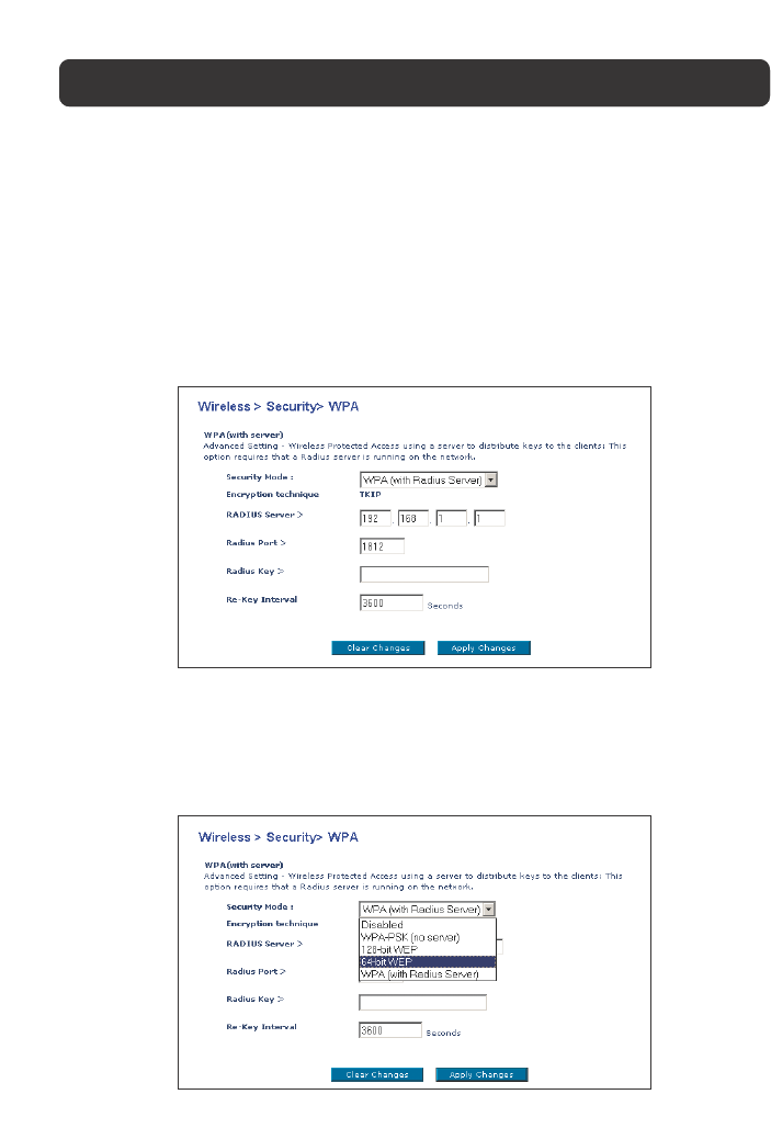
1. From the Security Mode drop-down menu, select “WPA (with server)”.
2. Enter the IP address of the radius server into the “Radius Server” fields.
3. Enter the radius key into the Radius Key field.
4. Enter the key interval. Key interval is how often the keys are distributed (in
packets).
5. Click “Apply Changes” to finish. You must now set all clients to match these
settings.
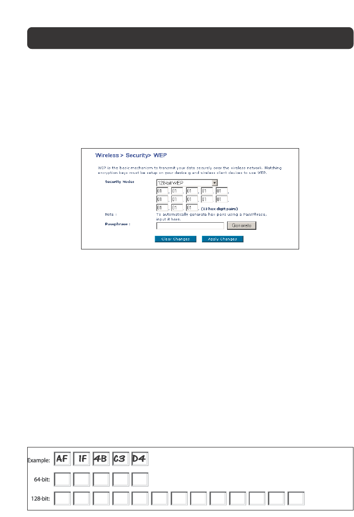
Setting WEP Encryption
Note to Mac users: The Passphrase option will not operate with Apple® AirPort®.
To configure encryption for your Mac computer, set the encryption using the
manual method described in the next section.
1. Select “128-bit WEP” or “64-bit WEP” from the drop-down menu.
UNDERSTANDING THE WEB-BASED USER INTERFACE
31
32
UNDERSTANDING THE WEB-BASED USER INTERFACE
2. After selecting your WEP encryption mode, you can enter you WEP key
manually by typing in the HEX WEP key manually, or you can type in a
Passphrase in the Passphrase field and click “Generate” to create a WEP key
from the passphrase. Click “Apply Changes” to finish. You must now set all of
your clients to match these settings.
3. Encryption in the Router is now set. Each of your computers on your wireless
network will now need to be configured with the same passphrase. Refer to
the documentation of your wireless network adapter for information on making
this change.
Using a Hexadecimal Key
A hexadecimal key is a mixture of numbers and letters from A–F and 0–9. 64-bit
keys are five two-digit numbers. 128-bit keys are 13 two-digit numbers.
For instance:
AF 0F 4B C3 D4 = 64-bit key
C3 03 0F AF 0F 4B B2 C3 D4 4B C3 D4 E7 = 128-bit key
In the boxes below, make up your key by writing in two characters between A–F
and 0–9. You will use this key to program the encryption settings on your Router
and your wireless computers.

33
UNDERSTANDING THE WEB-BASED USER INTERFACE
Note to Mac users: Original Apple AirPort products support 64-bit encryption only.
Apple AirPort 2 products can support 64-bit or 128-bit encryption. Please check
your product to see which version you are using. If you cannot configure your
network with 128-bit encryption, try 64-bit encryption.
4. Firewall
Your Router is equipped with a firewall that will protect your network from a
wide array of common hacker attacks including:
•IP Spoofing
•Land Attack
•Ping of Death (PoD)
•Denial of Service (DoS)
•IP with zero length
•Smurf Attack
•TCP Null Scan
•SYN flood
•UDP flooding
•Tear Drop Attack
•ICMP defect
•RIP defect
•Fragment flooding
The firewall also masks common ports that are frequently used to attack
networks. These ports appear to be “Stealth”, meaning that essentially they do
not exist to a would-be hacker. You can turn the firewall function off if needed,
however, it is recommended that you leave the firewall enabled. Disabling the
firewall protection will not leave your network completely vulnerable to hacker
attacks, but it is recommended that you leave the firewall enabled.
34
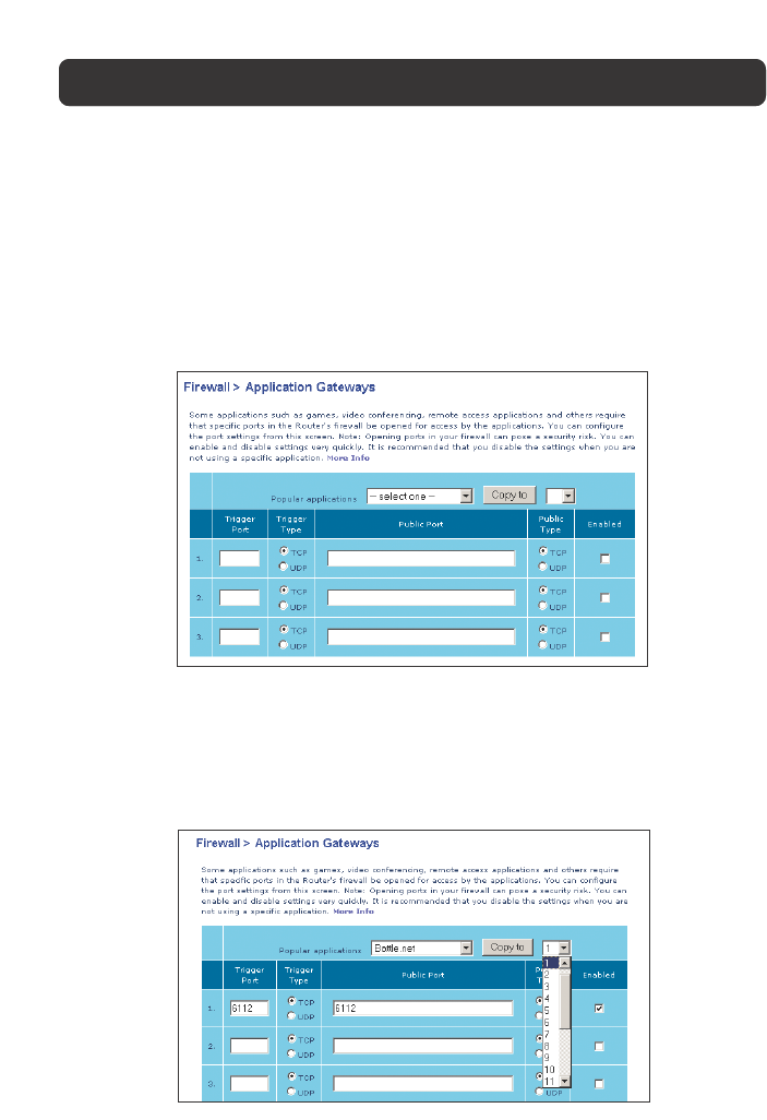
Application Gateways Settings
Application gateways let you select ports to be open for certain applications to
work properly with the Network Address Translation (NAT) feature of the Router. A
list of popular applications has been included to choose from. Select your
application from the drop-down list from the bottom of the screen. If your
application is not here, you will need to check with the application vendor to
determine which ports need to be configured. You can manually input this port
information into the Router.
Choosing an Application
Select the row that you want to copy the settings to from the drop-down list,
select the row you want to copy to, and then click “Copy To”. The settings will be
transferred to the row you specified. Click “Apply Changes” to save the setting for
that application.
UNDERSTANDING THE WEB-BASED USER INTERFACE
35
UNDERSTANDING THE WEB-BASED USER INTERFACE
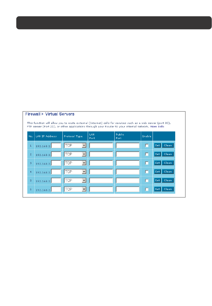
Virtual Servers
Virtual Servers allow you to route external (Internet) calls for services such as a
web server (port 80), FTP server (Port 21), or other applications, through your
Router to your internal network. Since your internal computers are protected by a
firewall, machines from the Internet cannot get to them because they cannot be
“seen”. If you need to configure the Virtual Server function for a specific
application, you will need to contact the application vendor to find out which
port settings you need.
Entering Settings into the Virtual Server
To enter settings, enter the last digit of your LAN IP address in the space
provided for the internal machine, input the Protocol Type (TCP or UDP), and the
LAN Port & Public Port number required to pass, select “Enable” and click “Set”.
Opening ports in your firewall can pose a security risk. You can enable and
disable settings very quickly. It is recommended that you disable the settings
when you are not using a specific application.
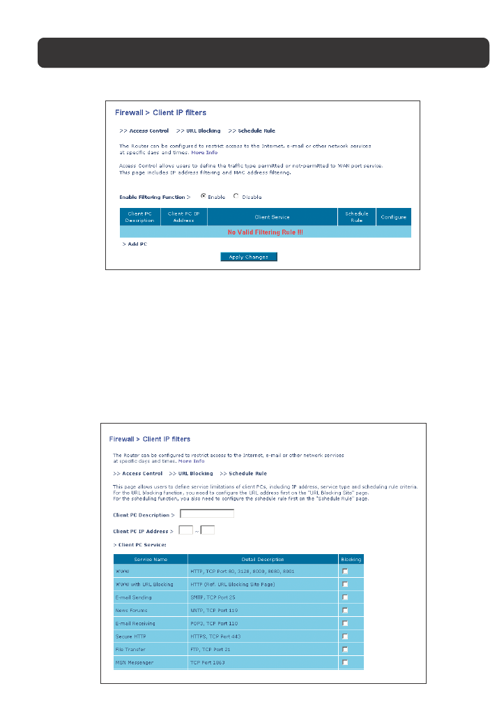
Client IP Filters
The Router can be configured to restrict access to the Internet, e-mail, or other
network services at specific days and times. Restriction can be set for a single
computer, a range of computers, or multiple computers.
36
UNDERSTANDING THE WEB-BASED USER INTERFACE
Access Control
Access Control allows users to define the outgoing traffic permitted or denied
access through the WAN interface. The default is to permit all outgoing traffic.
To configure restrictive access to your computers, do the following:
1. Click “Add PC” on the Access Control screen.
2. Define the appropriate settings for client PC services (as shown on the
following screen).
3. Click “OK” and then click “Apply Changes” to save your settings.
37
UNDERSTANDING THE WEB-BASED USER INTERFACE
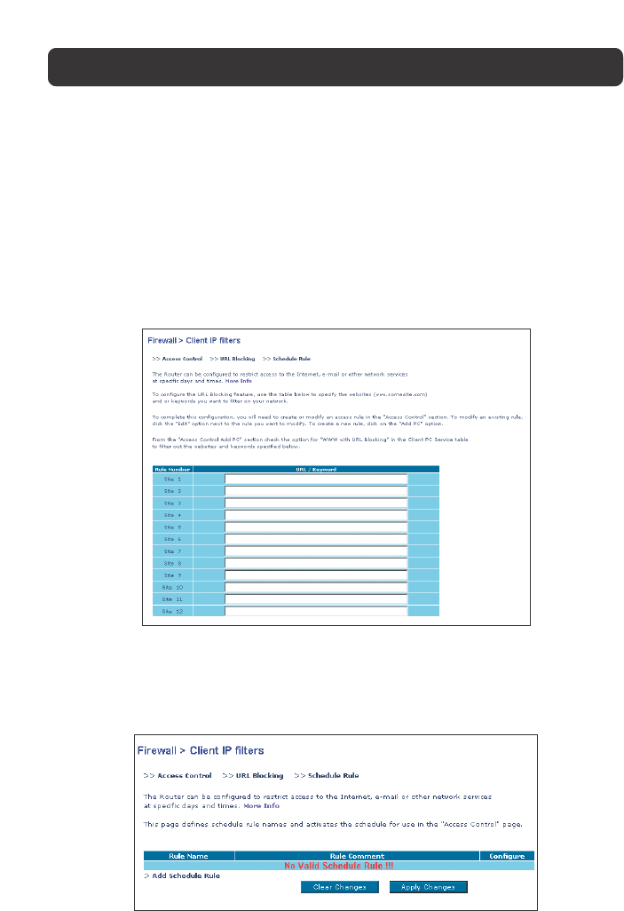
URL Blocking
To configure the URL Blocking feature, specify the websites
(www.anywebsite.com) and or keywords you want to filter on your network. Click
“Apply Changes” to activate the change. To complete this configuration, you will
need to create or modify an access rule in the “Client IP filters” section. To
modify an existing rule, click the “Edit” option next to the rule you want to
modify. To create a new rule, click on the “Add PC” option. From the “Access
Control > Add PC” section, check the option for “WWW with URL Blocking” in the
Client PC Service table to filter out the websites and keywords specified.
Schedule Rule
You may filter Internet access for local clients based on rules. Each access
control rule may be activated at a scheduled time. Define the schedule on the
“Schedule Rule”, and apply the rule on the “Access Control” page.
38
UNDERSTANDING THE WEB-BASED USER INTERFACE
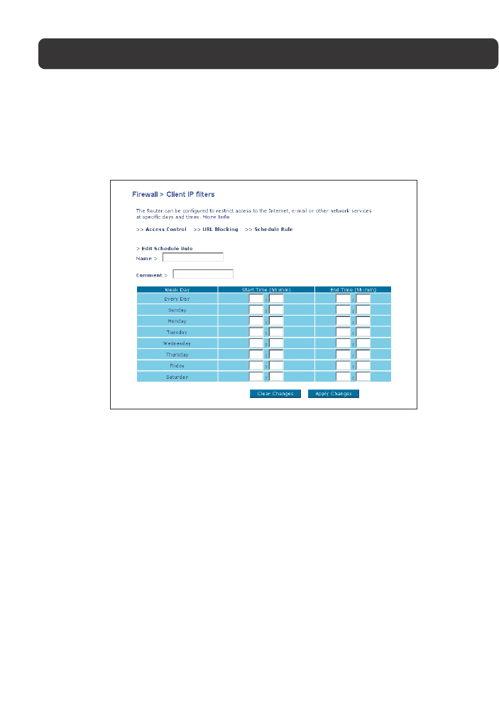
Follow these steps to add a schedule:
1. Click “Add Schedule Rule”.
2. You will see the following screen.
3. To configure the Schedule Rule, specify the Name, Comment, Start Time, and
End Time that you want to filter on your network.
4. Click “OK” and then “Apply Changes” to save your settings.
5. To complete this configuration, you will need to create or modify an access
rule in the Client IP filters section. This activates the schedule for use in the
“Access Control” page.
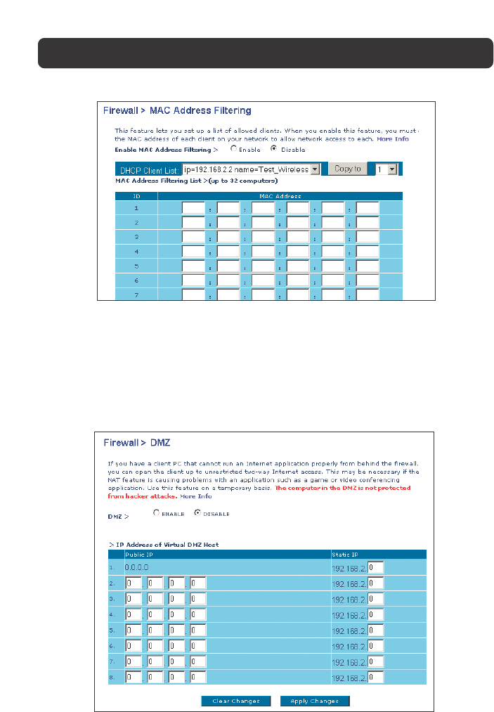
MAC Address Filtering
The MAC Address Filter is a powerful security feature that allows you to specify
which computers are allowed on the network. Any computer attempting to access
the network that is not specified in the filter list will be denied access. When you
enable this feature, you must enter the MAC address of each client on your
network to allow network access to each, or copy the MAC address by selecting
the name of the computer from the “DHCP Client List”. To enable this feature,
select “Enable”. Next, click “Apply Changes” to save the settings.
39
UNDERSTANDING THE WEB-BASED USER INTERFACE
DMZ (Demilitarized Zone)
If you have a client PC that cannot run an Internet application properly from
behind the firewall, you can open the client up to unrestricted two-way Internet
access. This may be necessary if the NAT feature is causing problems with an
application such as a game or video conferencing application. Use this feature on a
temporary basis. The computer in the DMZ is not protected from hacker attacks.
40
UNDERSTANDING THE WEB-BASED USER INTERFACE
To put a computer in the DMZ, enter the last digits of its LAN IP address in the
Static IP field and click “Apply Changes” for the change to take effect.
If you are using multiple Public (WAN) IP addresses, it is possible to select
which Public (WAN) IP address the DMZ host will be directed to. Type in the
Public (WAN) IP address you wish the DMZ host to direct to, enter the last two
digits of the IP address of the DMZ host computer, and click “Apply Changes”.
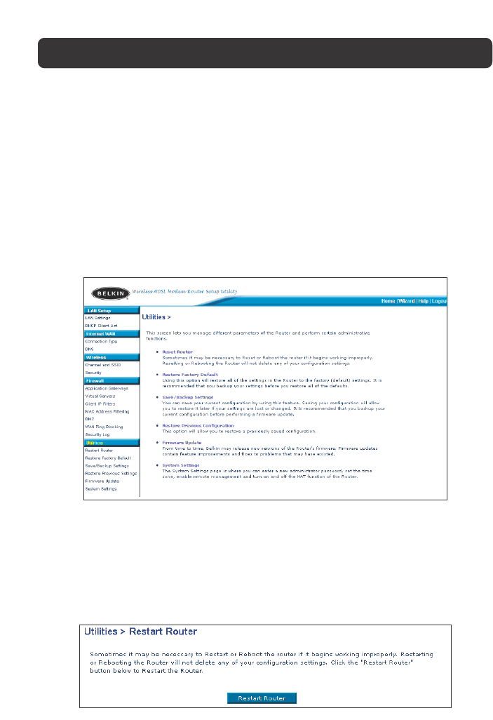
Utilities
The Utilities screen lets you manage different parameters of the Router and
perform certain administrative functions.
Restart Router
Sometimes it may be necessary to restart or reboot the Router if it begins
working improperly. Restarting or rebooting the Router will NOT delete any of
your configuration settings.