Belkin F5D7630-4A ADSL Modem with Built-in Wireless Router User Manual 23MS293 F5D7630 4A man
Belkin International, Inc. ADSL Modem with Built-in Wireless Router 23MS293 F5D7630 4A man
Belkin >
Contents
- 1. User Manual Part 1
- 2. User Manual Part 2
User Manual Part 2
41
UNDERSTANDING THE WEB-BASED USER INTERFACE
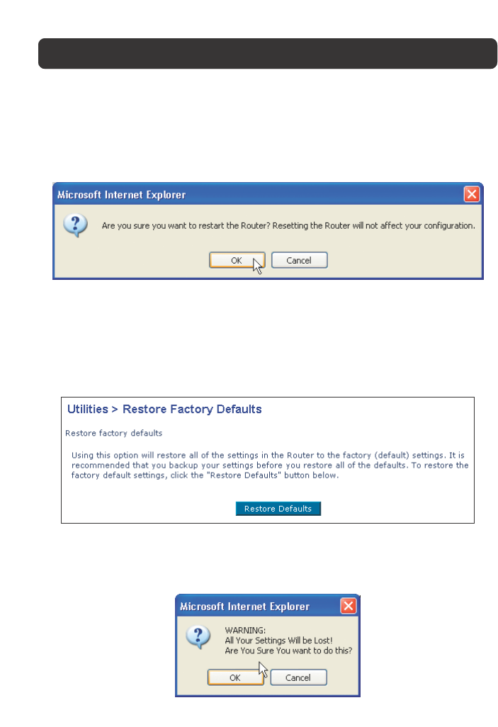
Restarting the Router to Restore Normal Operation
1. Click the “Restart Router” button.
2. The following message will appear. Click “OK” to restart your Router.
Restore Factory Defaults
Using this option will restore all of the settings in the Router to the factory
(default) settings. It is recommended that you back up your settings before you
restore all of the defaults.
1. Click the “Restore Defaults” button.
2. The following message will appear. Click “OK” to restore factory defaults.
42
UNDERSTANDING THE WEB-BASED USER INTERFACE
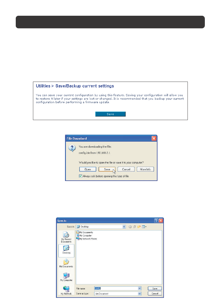
Saving/Backup Current Settings
You can save your current configuration by using this feature. Saving your
configuration will allow you to restore it later if your settings are lost or
changed. It is recommended that you back up your current configuration before
performing a firmware update.
1. Click “Save”. A window called “File Download” will open. Click “Save”.
2. A window will open that allows you to select the location in which to save
the configuration file. Select a location. There are no restrictions on the file
name, however, be sure to name the file so you can locate it yourself later.
When you have selected the location and entered the file name, click “Save”.
43
UNDERSTANDING THE WEB-BASED USER INTERFACE
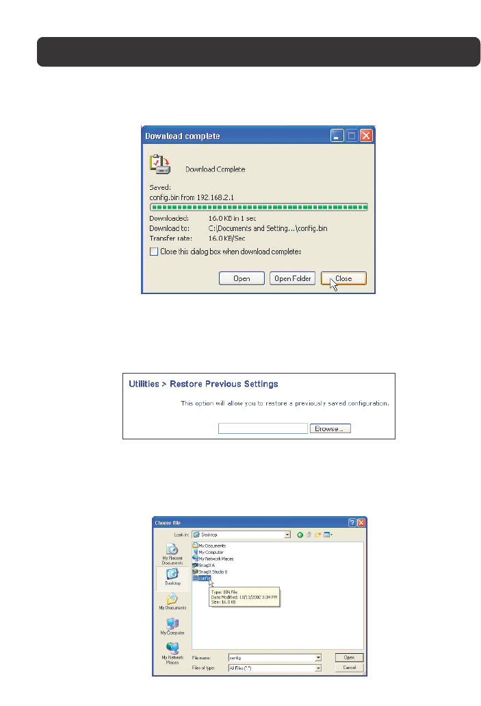
3. When the save is complete, you will see the window below. Click “Close”.
The configuration is now saved.
Restore Previous Settings
This option will allow you to restore a previously saved configuration.
1. Click “Browse”. A window will open that allows you to select the location of
the configuration file. All configuration files end with a “.bin”. Locate the
configuration file you want to restore and double-click on it.
2. Then, click “Restore”.
44
UNDERSTANDING THE WEB-BASED USER INTERFACE
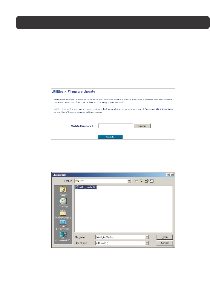
Firmware Update
From time to time, Belkin may release new versions of the Router’s firmware.
Firmware updates contain feature improvements and fixes to problems that may
have existed. When Belkin releases new firmware, you can download the firmware
from the Belkin update website and update your Router’s firmware to the latest
version.
Updating the Router’s Firmware
1. In the “Firmware Update” page, click “Browse”. A window will open that allows
you to select the location of the firmware update file.
2. Browse to the firmware file you downloaded. Select the file by double-clicking
on the file name.
3. Click “Update” to upgrade to the latest firmware version.
System Settings
The “System Settings” page is where you can enter a new administrator password,
set the time zone, enable remote management, and turn on and off the UPnP
function of the Router.
45
UNDERSTANDING THE WEB-BASED USER INTERFACE
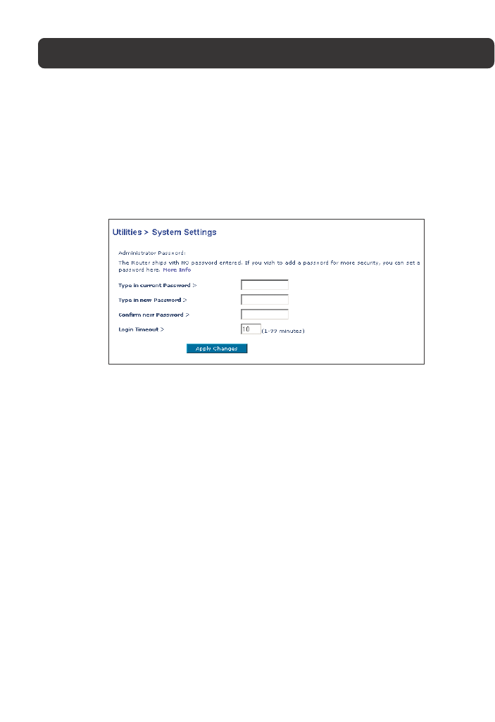
Setting or Changing the Administrator Password
The Router ships with NO password entered. If you wish to add a password for
greater security, you can set a password here. Write down your password and
keep it in a safe place, as you will need it if you need to log into the Router in
the future. It is also recommended that you set a password if you plan to use the
remote management feature of your Router.
Changing the Login Time-Out Setting
The login time-out option allows you to set the period of time that you can be
logged into the Router’s advanced setup interface. The timer starts when there
has been no activity. For example, you have made some changes in the advanced
setup interface, then left your computer alone without clicking “Logout”.
Assuming the time-out is set to 10 minutes, then 10 minutes after you leave, the
login session will expire. You will have to login to the Router again to make any
more changes. The login time-out option is for security purposes and the default
is set to 10 minutes.
Note: Only one computer can be logged into the Router’s advanced setup interface
at one time.
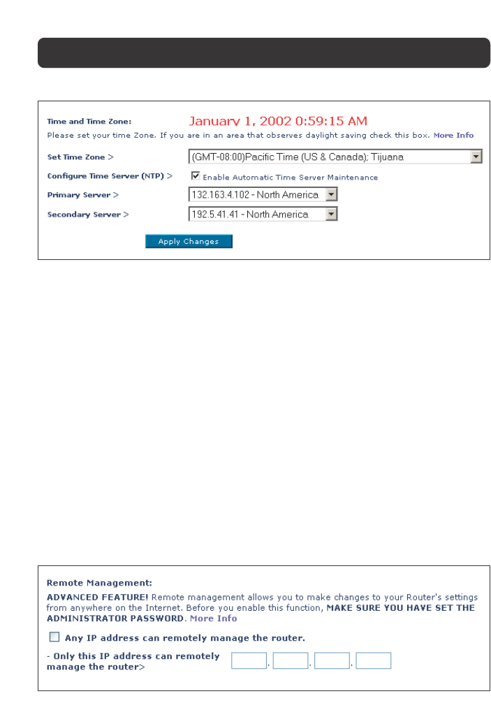
Setting the Time and Time Zone
The Router keeps time by connecting to a Simple Network Time Protocol (SNTP)
server. This allows the Router to synchronize the system clock to the global
Internet. The synchronized clock in the Router is used to record the security log
and control client filtering. Select the time zone that you reside in. The system
clock may not update immediately. Allow at least 15 minutes for the Router to
contact the timeservers on the Internet and get a response. You cannot set the
clock yourself.
46
UNDERSTANDING THE WEB-BASED USER INTERFACE
Enabling Remote Management
Before you enable this advanced feature of your Belkin Router, MAKE SURE YOU
HAVE SET THE ADMINISTRATOR PASSWORD. Remote management allows you to
make changes to your Router’s settings from anywhere on the Internet. There are
two methods of remotely managing the Router. The first is to allow access to the
Router from anywhere on the Internet by selecting “Any IP address can remotely
manage the Router”. By typing in your WAN IP address from any computer on the
Internet, you will be presented with a login screen where you need to type in the
password of your Router. The second method is to allow a specific IP address only
to remotely manage the Router. This is more secure, but less convenient. To use
this method, enter the IP address you know you will be accessing the Router
from in the space provided and select “Only this IP address can remotely manage
the Router”. Before you enable this function, it is STRONGLY RECOMMENDED that
you set your administrator password. Leaving the password empty will potentially
open your Router to intrusion.
47
UNDERSTANDING THE WEB-BASED USER INTERFACE
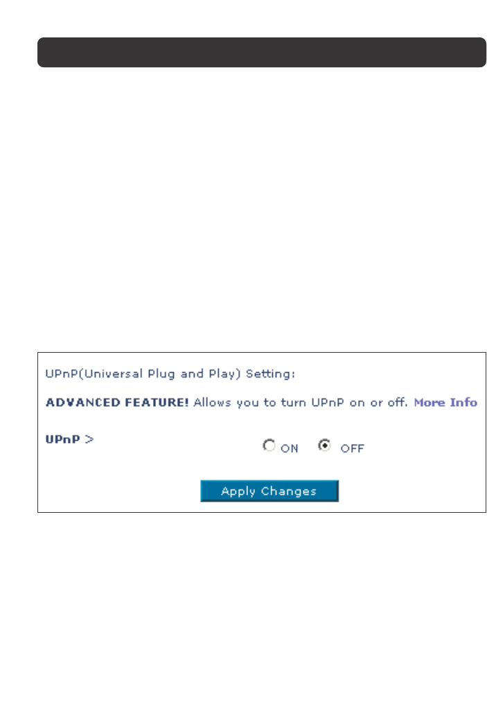
Enabling/Disabling UPnP
UPnP (Universal Plug-and-Play) is yet another advanced feature offered by your
Belkin Router. It is a technology that offers seamless operation of voice
messaging, video messaging, games, and other applications that are UPnP-
compliant. Some applications require the Router’s firewall to be configured in a
specific way to operate properly. This usually requires opening TCP and UDP
ports, and in some instances, setting trigger ports. An application that is UPnP-
compliant has the ability to communicate with the Router, basically “telling” the
Router which way it needs the firewall configured. The Router ships with the
UPnP feature disabled. If you are using any applications that are UPnP-
compliant, and wish to take advantage of the UPnP features, you can enable the
UPnP feature. Simply select “Enable” in the “UPnP Enabling” section of the
“Utilities” page. Click “Apply Changes” to save the change.
48
MANUALLY CONFIGURING NETWORK SETTINGS
Set up the computer that is connected to the ADSL modem FIRST using these
steps. You can also use these steps to add computers to your Router after the
Router has been set up to connect to the Internet.
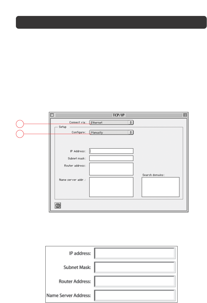
Manually Configuring Network Settings in Mac OS up to 9.x
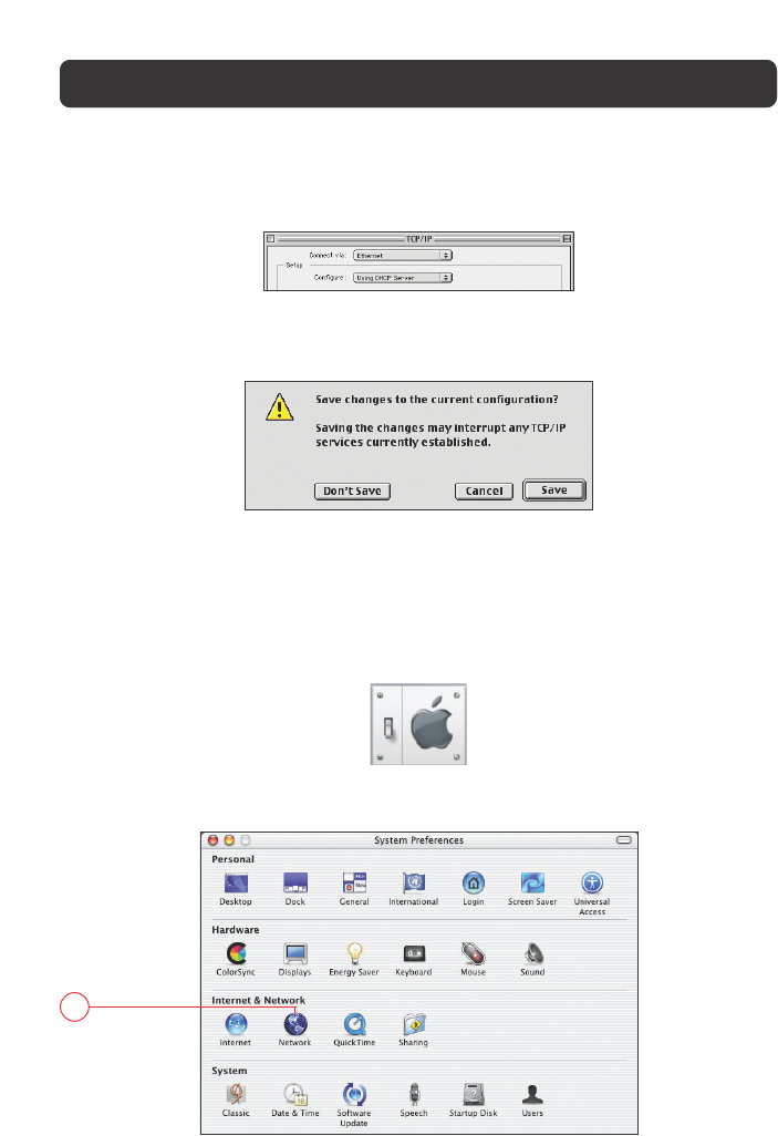
1. Pull down the Apple menu. Select “Control Panels” and select “TCP/IP”.
2. You will see the TCP/IP control panel. Select “Ethernet Built-In” or “Ethernet”
in the “Connect via:” drop-down menu (1).
1
2
3. Next to “Configure” (2), if “Manually” is selected, your Router will need to be
set up for a static IP connection type. Write the address information in the
table below. You will need to enter this information into the Router.
MANUALLY CONFIGURING NETWORK SETTINGS
4. If not already set, at “Configure:”, choose “Using DHCP Server”. This will tell
the computer to obtain an IP address from the Router.
5. Close the window. If you made any changes, the following window will appear.
Click “Save”.
Restart the computer. When the computer restarts, your network settings are now
configured for use with the Router.
Manually Configuring Network Settings in Mac OS X
1. Click on the “System Preferences” icon.
2. Select “Network” (1) from the “System Preferences” menu.
1
49
50
MANUALLY CONFIGURING NETWORK SETTINGS
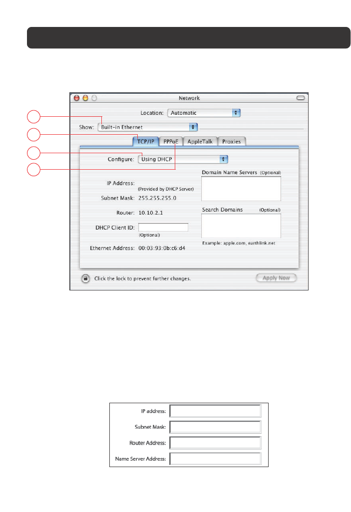
3. Select “Built-in Ethernet” (2) next to “Show” in the Network menu.
2
3
4
5
4. Select the “TCP/IP” tab (3). Next to “Configure” (4), you should see
“Manually” or “Using DHCP”. If you do not, check the PPPoE tab (5) to make
sure that “Connect using PPPoE” is NOT selected. If it is, you will need to
configure your Router for a PPPoE connection type using your user name and
password.
5. If “Manually” is selected, your Router will need to be set up for a static IP
connection type. Write the address information in the table below. You will
need to enter this information into the Router.
6. If not already selected, select “Using DHCP” next to “Configure” (4), then click
“Apply Now”.
Your network settings are now configured for use with the Router.
51
MANUALLY CONFIGURING NETWORK SETTINGS
Manually Configuring Network Settings in Windows 2000, NT, or XP
1. Click “Start”, “Settings”, then “Control Panel”.
2. Double-click on the “Network and dial-up connections” icon (Windows 2000)
or the “Network” icon (Windows XP).
3. Right-click on the “Local Area Connection” associated with your network
adapter and select “Properties” from the drop-down menu.
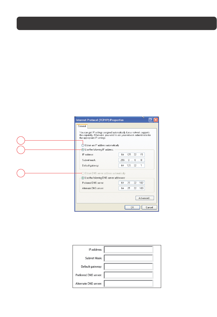
4. In the “Local Area Connection Properties” window, click “Internet Protocol
(TCP/IP)” and click the “Properties” button. The following screen will appear:
1
2
3
5. If “Use the following IP address” (2) is selected, your Router will need to be
set up for a static IP connection type. Write the address information the table
below. You will need to enter this information into the Router.
6. If not already selected, select “Obtain an IP address automatically” (1) and
“Obtain DNS server address automatically” (3). Click “OK”.
Your network settings are now configured for use with the Router.
52
MANUALLY CONFIGURING NETWORK SETTINGS
Manually Configuring Network Settings in Windows 98 or Me
1. Right-click on “My Network Neighborhood” and select “Properties” from the
drop-down menu.
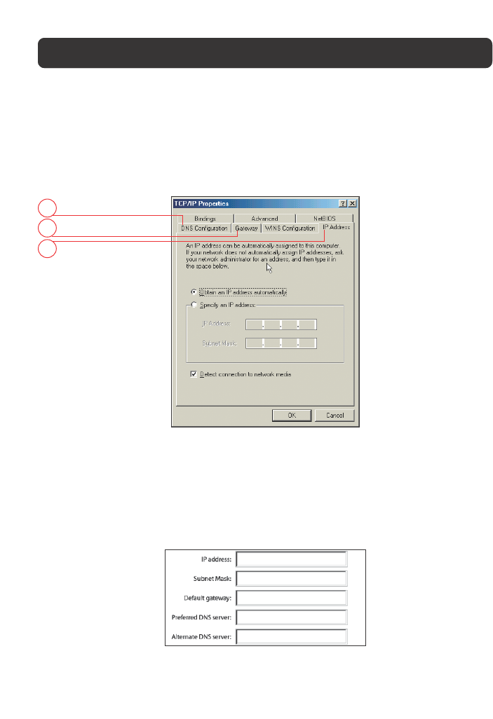
2. Select “TCP/IP > Settings” for your installed network adapter. You will see the
following window.
1
2
3
3. If “Specify and IP address” is selected, your Router will need to be set up for
a static IP connection type. Write the address information in the table below.
You will need to enter this information into the Router.
4. Write the IP address and subnet mask from the “IP Address” tab (3).
5. Click the “Gateway” tab (2). Write the gateway address down in the chart.
6. Click the “DNS Configuration” tab (1). Write the DNS address(es) in the chart.
7. If not already selected, select “Obtain IP address automatically” on the IP
address tab. Click “OK”.
Restart the computer. When the computer restarts, your network settings are now
configured for use with the Router.
53
MANUALLY CONFIGURING NETWORK SETTINGS
Recommended Web Browser Settings
In most cases, you will not need to make any changes to your web browser’s
settings. If you are having trouble accessing the Internet or the Web-Based
Advanced User Interface, then change your browser’s settings to the
recommended settings in this section.
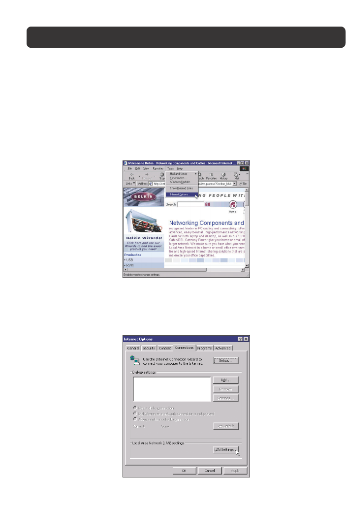
Microsoft Internet Explorer 4.0 or Higher
1. Start your web browser. Select “Tools” then “Internet Options”.
2. In the “Internet Options” screen, there are three selections: “Never dial a
connection”, “Dial whenever a network connection is not present”, and “Always
dial my default connection”. If you can make a selection, select “Never dial a
connection”. If you cannot make a selection, go to the next step.
3. Under the “Internet Options” screen, click on “Connections” and select “LAN
Settings”.
54
MANUALLY CONFIGURING NETWORK SETTINGS
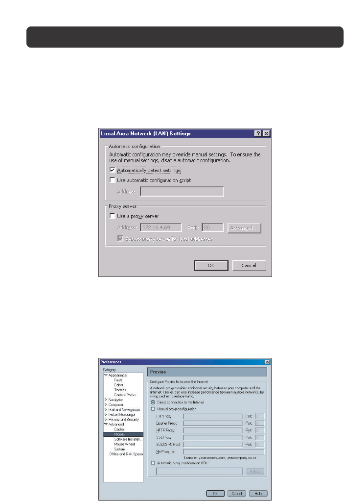
4. Make sure there are no check marks next to any of the displayed options:
“Automatically detect settings”, “Use automatic configuration script”, and
“Use a proxy server”. Click “OK”. Then click “OK” again in the “Internet
Options” page.
Netscape Navigator 4.0 or Higher
1. Start Netscape. Click on “Edit” then “Preferences”.
2. In the “Preferences” window, click on “Advanced” then select “Proxies”. In the
“Proxies” window, select “Direct connection to the Internet”.

55
GLOSSARY
IP address
The “IP address” is the Internal IP address of the Router. To access the advanced
setup interface, type this IP address into the address bar of your browser. This
address can be changed if needed. To change the IP address, type in the new IP
address and click “Apply Changes”. The IP address you choose should be a
non-routable IP. Examples of a non-routable IP are:
192.168.x.x (where x is anything between 0 and 255.)
10.x.x.x (where x is anything between 0 and 255.)
Subnet Mask
Some networks are far too large to allow all traffic to flood all its parts. These
networks must be broken down into smaller, more manageable sections, called
subnets. The subnet mask is the network address plus the information reserved
for identifying the “subnetwork”.
DNS
DNS is an acronym for Domain Name Server. A Domain Name Server is a server
located on the Internet that translates URLs (Universal Resource Links) like
www.belkin.com to IP addresses. Many ISPs do not require you to enter this
information into the Router. If you are using a static IP connection type, then
you may need to enter a specific DNS address and secondary DNS address for your
connection to work properly. If your connection type is Dynamic or PPPoE, it is
likely that you do not have to enter a DNS address.
PPPoE (Routing Mode, for multiple PCs)
Most ADSL providers use PPPoE as the connection type. If you use an ADSL
modem to connect to the Internet, your ISP may use PPPoE to log you into the
service.
Your connection type is PPPoE if:
1. Your ISP gave you a user name and password which is required to connect to
the Internet
2. Your ISP gave you software such as WinPoET, Enternet300 that you use to
connect to the Internet

56
GLOSSARY
3. You have to double-click on a desktop icon other than your browser to get on
the Internet
To set the Router to use PPPoE, type in your user name and password in the
spaces provided. After you have typed in your information, click “Apply Changes”.
After you apply the changes, the Internet Status indicator will read “connection
OK” if your Router is set up properly.
PPPoA (Routing Mode, for multiple PCs)
Enter the PPPoA information in the provided spaces, and click “Next”. Click
“Apply” to activate your settings.
a. User name - Enter the ISP assigned user name. (Assigned by your ISP).
b. Password - Enter your password. (Assigned by your ISP).
c. Retype Password - Confirm the password. (Assigned by your ISP).
d. VPI/VCI - Enter your Virtual Path Identifier (VPI) and Virtual Circuit Identifier
(VCI) parameter here. (Assigned by your ISP).
Disconnect after X...
This feature is used to automatically disconnect the Router from your ISP when
there is no activity for a specified period of time. For instance, placing a check
mark next to this option and entering “5” into the minute field will cause the
Router to disconnect from the Internet after five minutes of no Internet activity.
This option should be used if you pay for your Internet service by the minute.
Channel and SSID
To change the channel of operation of the Router, select the desired channel from
the drop-down menu and select your channel. Click “Apply Changes” to save the
setting. You can also change the SSID. The SSID is the equivalent to the wireless
network's name. You can make the SSID anything you want to. If there are other
wireless networks in your area, you should give your wireless network a unique
name. Click inside of the SSID box and type in a new name. Click “Apply Changes”
to make the change.

57
ESSID Broadcast
Many wireless network adapters currently on the market possess a feature known
as site survey. It scans the air for any available network and allows each
computer to automatically select a network from the survey. This occurs if the
computer’s SSID is set to "ANY”. Your Belkin Router can block this random search
for a network. If you disable the "ESSID Broadcast" feature, the only way a
computer can join your network is by its SSID being set to the specific name of
the network (like WLAN). Be sure that you know your SSID (network name)
before enabling this feature. It is possible to make your wireless network nearly
invisible. By turning off the broadcast of the SSID, your network will not appear
in a site survey. Obviously, turning off the broadcast feature of the SSID helps
increase security.
Encryption
Setting encryption can help keep your network secure. The Router uses Wired
Equivalent Privacy (WEP) encryption to protect your data and features two rates
of encryption: 64-bit and 128-bit. Encryption works on a system of keys. The key
on the computer must match the key on the Router, and there are two ways to
make a key. The easiest is to let the Router’s software convert a passphrase
you’ve created into a key. The advanced method is to enter the keys manually.
Application Gateways
Application Gateways let you specify specific ports to be open for specific
applications to work properly with the Network Address Translation (NAT) feature
of the Router. A list of popular applications has been included. You can select an
application from the popular choices included in the drop-down list. Your
selections will be programmed into the Router. From the drop-down list, select
the row that you want to copy the settings from, and the row you want to copy
to, and then click "Copy To". The settings will be transferred to the row you
specified. Click "Apply Changes" to save the setting for that application. If your
application is not here, you will need to check with the application vendor to
determine which ports need to be configured. You can manually input this port
information into the Router.
GLOSSARY

58
GLOSSARY
Virtual Servers
This function will allow you to route external (Internet) calls for services such as
a web server (port 80), FTP server (Port 21), or other applications through your
Router to your internal network. Since your internal computers are protected by a
firewall, machines from the Internet cannot get to them because they cannot be
“seen”. If you need to configure the Virtual Server function for a specific
application, you will need to contact the application vendor to find out which
port settings you need. To manually enter settings, enter the IP address in the
space provided for the internal machine, the port type (TCP or UDP), and the LAN
& Public port(s) required to pass, select “Enable” and click “Set”. You can only
pass one port per internal IP address. Opening ports in your firewall can pose a
security risk. You can enable and disable settings very quickly. It is recommended
that you disable the settings when you are not using a specific application.
Client IP filters
The Router can be configured to restrict access to the Internet, e-mail or other
network services at specific days and times. Restriction can be set for a single
computer, a range of computers, or multiple computers.
URL Blocking
To configure the URL Blocking feature, specify the websites (www.somesite.com)
and or keywords you want to filter on your network. Click “Apply Changes” to
activate the change. To complete this configuration, you will need to create or
modify an access rule in the Client IP filters section. To modify an existing rule,
click the “Edit” option next to the rule you want to modify. To create a new rule,
click on the “Add PC” option. From the “Access Control Add PC” section, check
the option for “WWW with URL Blocking” in the Client PC Service table to filter
out the websites and keywords specified.
Schedule Rule
To configure the Schedule Rule, specify the Name, Comment, Start Time, and End
Time that you want to filter on your network. This page defines schedule rule
names and activates the schedule for use in the “Access Control” page.

59
GLOSSARY
MAC Address Filtering
The MAC Address Filter is a powerful security feature that allows you to specify
which computers are allowed on the network. Any computer attempting to access
the network that is not specified in the filter list will be denied access. When you
enable this feature, you must enter the MAC address of each client on your
network to allow network access to each or copy the MAC address by selecting
the name of the computer from the “DHCP Client List”. To enable this feature,
select “Enable”. Next, click “Apply Changes” to save the settings.
DMZ
If you have a client PC that cannot run an Internet application properly from
behind the firewall, you can open the client up to unrestricted two-way Internet
access. This may be necessary if the NAT feature is causing problems with an
application such as a game or video conferencing application. Use this feature on
a temporary basis. The computer in the DMZ is not protected from hacker
attacks. To put a computer in the DMZ, enter the last digits of its LAN IP address
in the Static IP field and click “Apply Changes” for the change to take effect.
If you have only one Public (WAN) IP address, then you can leave the Public IP
to 0.0.0.0. If you are using multiple Public (WAN) IP addresses, it is possible to
select which Public (WAN) IP address the DMZ host will be directed to. Type in
the Public (WAN) IP address you wish the DMZ host to direct to, enter the last
two digits of the IP address of the DMZ host computer, and click “Apply Changes”.
Administrator Password
The Router ships with NO password entered. If you wish to add a password for
more security, you can set a password from your Router’s web-based user
interface. Keep your password in a safe place as you will need this password if
you need to log into the Router in the future. It is STRONGLY RECOMMENDED
that you set a password if you plan to use the remote management feature.
The login time-out option allows you to set the period of time that you can be
logged into the Router's advanced setup interface. The timer starts when there
has been no activity. For example, you have made some changes in the advanced
setup interface, then left your computer alone without clicking “Logout”.

60
GLOSSARY
Assuming the time-out is set to 10 minutes, then 10 minutes after you leave, the
login session will expire. You will have to login to the Router again to make any
more changes. The login time-out option is for security purposes and the default
is set to 10 minutes. Note, only one computer can be logged into the Router’s
advanced setup interface at a time.
Time and Time Zone
The Router keeps time by connecting to a Simple Network Time Protocol (SNTP)
server. This allows the Router to synchronize the system clock to the global
Internet. The synchronized clock in the Router is used to record the security log
and control client filtering. Select the time zone that you reside in. If you reside
in an area that observes daylight saving time, then place a check mark in the box
next to “Enable Daylight Saving”. The system clock may not update immediately.
Allow at least 15 minutes for the Router to contact the timeservers on the
Internet and get a response. You cannot set the clock yourself.
Remote Management
Before you enable this function, MAKE SURE YOU HAVE SET THE
ADMINISTRATOR PASSWORD. Remote management allows you to make changes
to your Router’s settings from anywhere on the Internet.
UPnP
UPnP (Universal Plug-and-Play) is a technology that offers seamless operation of
voice messaging, video messaging, games, and other applications that are UPnP-
compliant. Some applications require the Router's firewall to be configured in a
specific way to operate properly. This usually requires opening TCP and UDP ports
and in some instances setting trigger ports. An application that is UPnP-
compliant has the ability to communicate with the Router, basically “telling” the
Router which way it needs the firewall configured. The Router ships with the
UPnP feature disabled. If you are using any applications that are UPnP-
compliant, and wish to take advantage of the UPnP features, you can enable the
UPnP feature. Simply select “Enable” in the “UPnP Enabling” section of the
Utilities page. Click “Apply Changes” to save the change.

61
TROUBLESHOOTING
You can find technical support information at www.belkin.com/networking or
www.belkin.com through the tech support area. If you want to contact technical
support by phone, please call 877-736-5771. Technical support is available
24-hours-a-day, 7-days-a-week.
Problem
The ADSL SYN LED is not on.
The ADSL Data LED is not on.
My connection type is static
IP address. I cannot connect
to the Internet.
Possible Cause/Solution
1. Check the connection between the Modem
Router and ADSL line. Make sure the cable
from the ADSL line is connected to the port
on the Router labeled “ADSL”.
2. Make sure the Router has power. The “PWR”
LED of the front panel should be illuminated.
1. Make sure the cable from the ADSL line is
connected to the port on the Router labeled
“ADSL” and the “SYN” LED is on.
2. Make sure you have the correct VPI/VCI, user
name, and password from your ISP provider.
Since your connection type is static IP address,
your ISP must assign you the IP address, subnet
mask, and gateway address. Instead of using the
Wizard, go to “Connection Type”, and then
select your connection type. Click “Next”, select
“Static IP”, and enter your IP address, subnet
mask, and default gateway information.

62
TROUBLESHOOTING
I’ve forgotten or lost my
password.
My wireless PC cannot
connect to the Router.
The wireless network is
often interrupted.
Press the Reset button on the rear panel
(holding it down for at least five seconds) to
restore the factory defaults.
1. Make sure the wireless PC has the same SSID
settings as the Router, and you have the
same security settings on the clients such as
WPA or WEP encryption.
2. Make sure the distance between the Router
and wireless PC are not too far away.
1. Move your wireless PC closer to the Router to
find a better signal.
2. There may also be interference, possibly
caused by a microwave oven or 2.4GHz
cordless phones. Change the location of the
Router or use a different wireless channel.

63
INFORMATION
Caution: Exposure to Radio Frequency Radiation.
The radiated output power of this device is far below the FCC radio frequency exposure limits.
Nevertheless, the device shall be used in such manner that the potential for human contact
normal operation is minimized.
When connecting an external antenna to the device, the antenna shall be placed in such a
manner to minimize the potential for human contact during normal operation. In order to avoid
the possibility of exceeding the FCC radio frequency exposure limits, human proximity to the
antenna shall not be less than 20cm (8 inches) during normal operation.
Federal Communications Commission Notice
This equipment has been tested and found to comply with the limits for a Class B digital device,
pursuant to Part 15 of the FCC Rules. These limits are designed to provide reasonable protection
against harmful interference in a residential installation.
This equipment generates, uses, and can radiate radio frequency energy. If not installed and used
in accordance with the instructions, it may cause harmful interference to radio or television
reception, which can be determined by turning the equipment off and on, the user is encouraged
to try and correct the interference by one or more of the following measures:
• Reorient or relocate the receiving antenna.
• Increase the distance between the equipment and the receiver.
• Connect the equipment to an outlet on a circuit different from that to which the receiver
is connected.
• Consult the dealer or an experienced radio/TV technician for help.
Modifications
The FCC requires the user to be notified that any changes or modifications to this device that
are not expressly approved by Belkin Corporation may void the users authority to operate
the equipment.
FCC Statement
DECLARATION OF CONFORMITY WITH FCC RULES FOR
ELECTROMAGNETIC COMPATIBILITY
We, Belkin Corporation, of 501 West Walnut Street, Compton, CA 90220, declare under our sole
responsibility that the product,
F5D7630-4
to which this declaration relates,
complies with Part 15 of the FCC Rules. Operation is subject to the following two conditions: (1) this
device may not cause harmful interference, and (2) this device must accept any interference received,
including interference that may cause undesired operation.
64
INFORMATION
Canada-Industry Canada (IC)
The wireless radio of this device complies with RSS 139 & RSS 210 Industry Canada. This Class B
digital complies with Canadian ICES-003.
Cet appareil numérique de la classe B conforme á la norme NMB-003 du Canada.
Europe-European Union Notice
Radio products with the CE 0682 or CE alert marking comply
with the R&TTE Directive (1995/5/EC) issued by the Commission of the
European Community.
Compliance with this directive implies conformity to the following European Norms (in brackets
are the equivalent international standards).
• EN 60950 (IEC60950) – Product Safety
• EN 300 328 Technical requirement for radio equipment
• ETS 300 826 General EMC requirements for radio equipment.
To determine the type of transmitter, check the identification label on your Belkin product.
Products with the CE marking comply with the EMC Directive (89/336/EEC) and the Low Voltage
Directive (72/23/EEC) issued by the Commission of the European Community. Compliance with
these directives implies conformity to the following European Norms (in brackets are the
equivalent international standards).
• EN 55022 (CISPR 22) – Electromagnetic Interference
• EN 55024 (IEC61000-4-2,3,4,5,6,8,11)- Electromagnetic Immunity
• EN 61000-3-2 (IEC610000-3-2) - Power Line Harmonics
• EN 61000-3-3 (IEC610000) – Power Line Flicker
• EN 60950 (IEC60950) – Product Safety
Products that contain the radio transmitter are labeled with CE 0682 or CE alert marking and may
also carry the CE logo.

65
INFORMATION
Belkin Corporation Limited Lifetime Product Warranty
Belkin Corporation warrants this product against defects in materials and workmanship for its
lifetime. If a defect is discovered, Belkin will, at its option, repair or replace the product at no
charge provided it is returned during the warranty period, with transportation charges prepaid, to
the authorized Belkin dealer from whom you purchased the product. Proof of purchase may be
required.
This warranty does not apply if the product has been damaged by accident, abuse, misuse, or
misapplication; if the product has been modified without the written permission of Belkin; or if
any Belkin serial number has been removed or defaced.
THE WARRANTY AND REMEDIES SET FORTH ABOVE ARE EXCLUSIVE IN LIEU OF ALL OTHERS,
WHETHER ORAL OR WRITTEN, EXPRESSED OR IMPLIED. BELKIN SPECIFICALLY DISCLAIMS ANY AND
ALL IMPLIED WARRANTIES, INCLUDING, WITHOUT LIMITATION, WARRANTIES OF MERCHANTABILITY
AND FITNESS FOR A PARTICULAR PURPOSE.
No Belkin dealer, agent, or employee is authorized to make any modification, extension, or
addition to this warranty.
BELKIN IS NOT RESPONSIBLE FOR SPECIAL, INCIDENTAL, OR CONSEQUENTIAL DAMAGES RESULTING
FROM ANY BREACH OF WARRANTY, OR UNDER ANY OTHER LEGAL THEORY, INCLUDING BUT NOT
LIMITED TO, LOST PROFITS, DOWNTIME, GOODWILL, DAMAGE TO OR REPROGRAMMING OR
REPRODUCING ANY PROGRAM OR DATA STORED IN, OR USED WITH, BELKIN PRODUCTS.
Some states do not allow the exclusion or limitation of incidental or consequential damages or
exclusions of implied warranties, so the above limitations of exclusions may not apply to you.
This warranty gives you specific legal rights, and you may also have other rights that vary from
state to state.

Belkin Corporation
501 West Walnut Street
Compton • CA • 90220 • USA
Tel: 310.898.1100
Fax: 310.898.1111
Belkin Components, Ltd.
Express Business Park • Shipton Way
Rushden • NN10 6GL • United Kingdom
Tel: +44 (0) 1933 35 2000
Fax: +44 (0) 1933 31 2000
Belkin Components B.V.
Starparc Building • Boeing Avenue 333
1119 PH Schiphol-Rijk • The Netherlands
Tel: +31 (0) 20 654 7300
Fax: +31 (0) 20 654 7349
Belkin, Ltd.
7 Bowen Crescent • West Gosford
NSW 2250 • Australia
Tel: +61 (0) 2 4372 8600
Fax: +61 (0) 2 4372 8603
Belkin Tech Support
US: 877.736.5771
310.898.1100 ext. 2263
Europe: 00 800 223 55 460
Australia: 1800 666 040
23MS293
© 2003 Belkin Corporation. All rights reserved. All trade names are
registered trademarks of respective manufacturers listed. Mac, Mac OS, AppleTalk, Apple,
and AirPort are trademarks of Apple Computer, Inc., registered in the U.S. and other countries.
belkin.com