Belkin F5D8236V3 N Wireless Router User Manual Manual Part 2
Belkin International, Inc. N Wireless Router Manual Part 2
UserManual.wiki
>
Belkin
>
F5D8236V3 User Manual
>
Manual Part 2
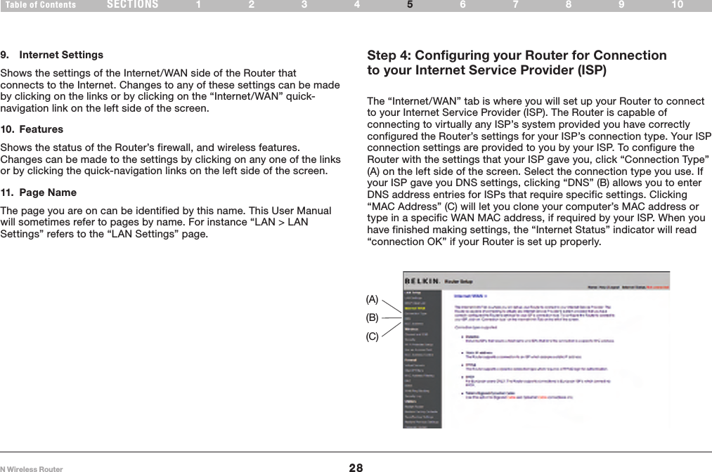
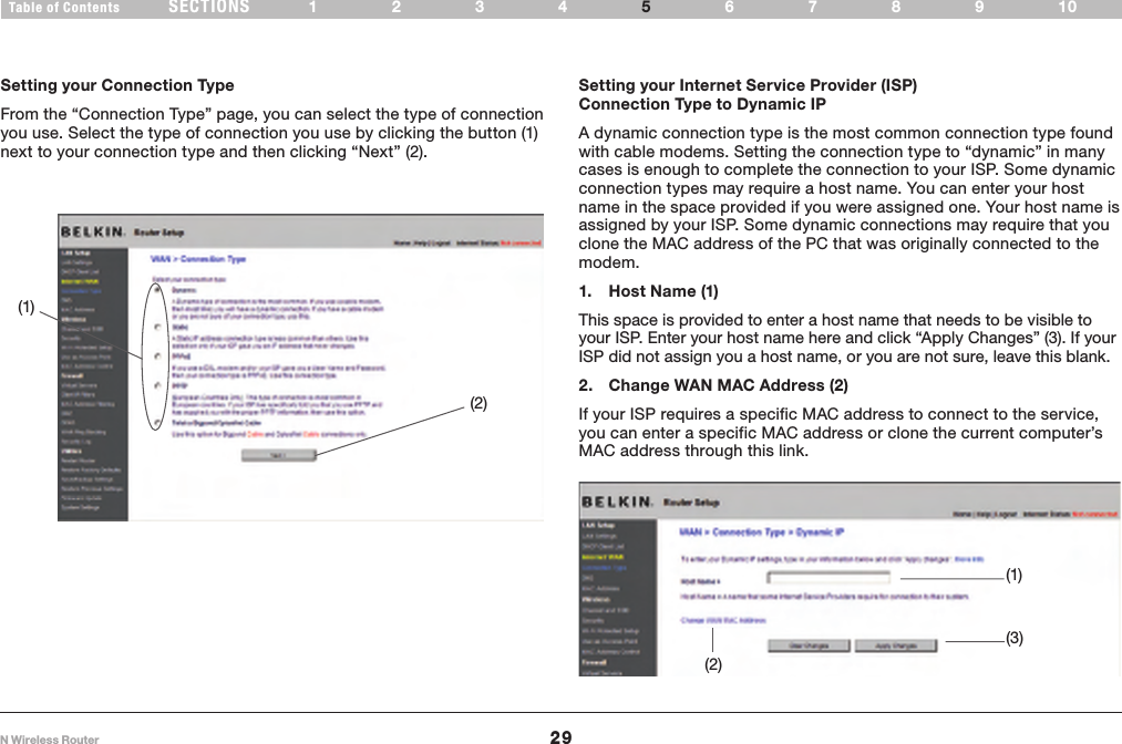
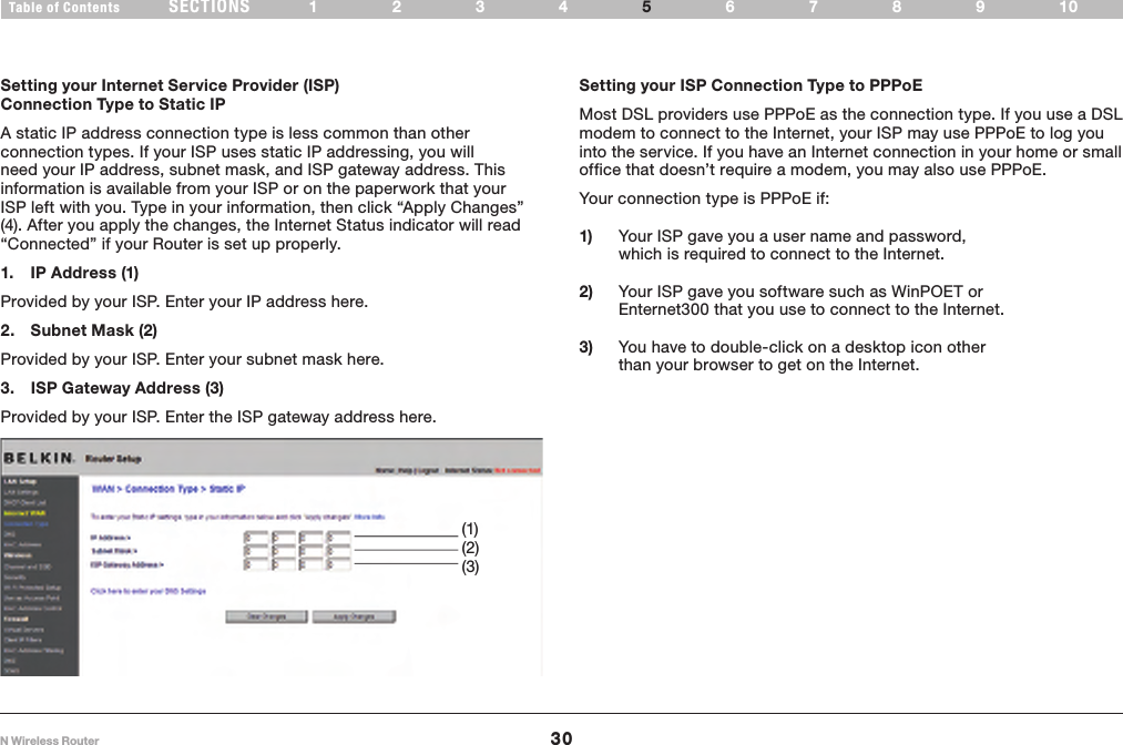
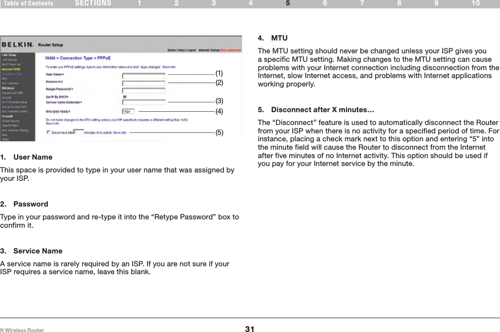
Contents
1.
Manual part 1
2.
Manual Part 2
3.
Manual Part 3
4.
Manual Part 4
Manual Part 2
Navigation menu
Upload a User Manual
Namespaces
Wiki Guide
HTML
PDF
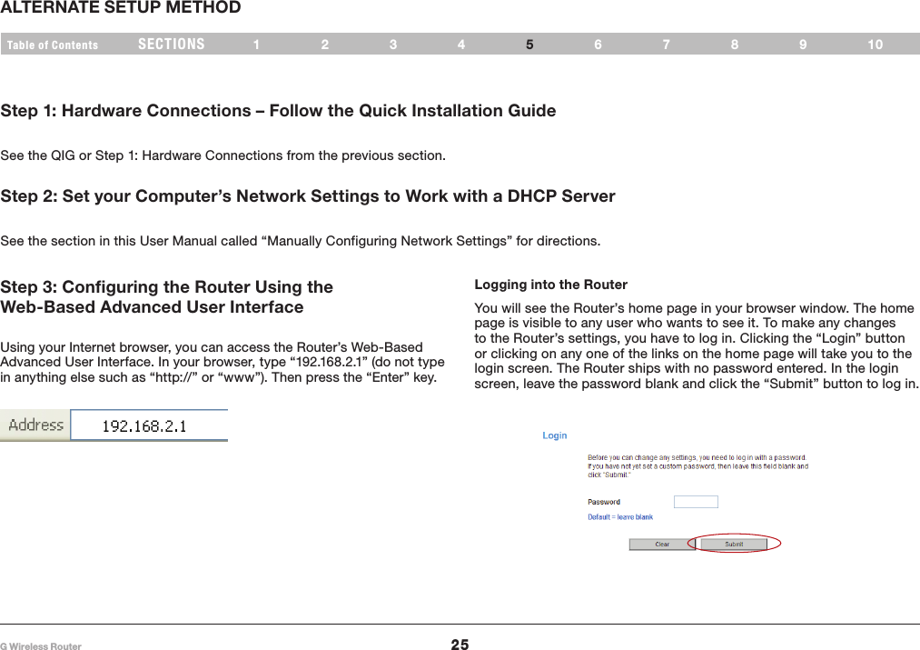
Info
Views
User Manual
Discussion / Help
Navigation
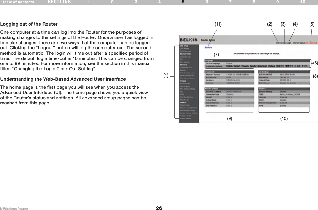
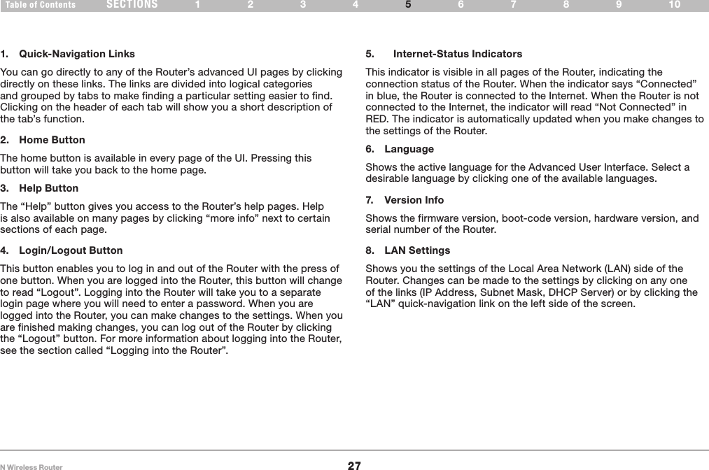
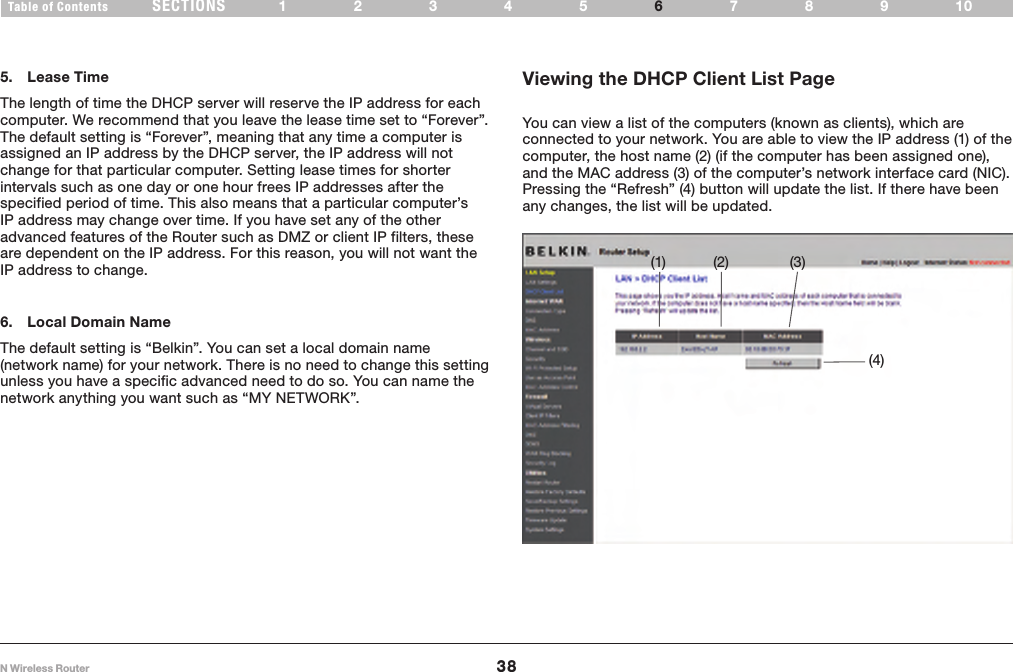
![32N Wireless RouterSECTIONSTable of Contents 1234 6789105ALTERNATE SETUP METHOD (1)(2)(4)(5)(3)(6)Setting your Internet Service Provider (ISP) Connection Type to Point-to-Point Tunneling Protocol (PPTP) [European Countries Only] Some ISPs require a connection using PPTP protocol, a type of connection most common in European countries. This sets up a direct connection to the ISP’s system. Type in the information provided by your ISP in the space provided. When you have finished, click “Apply Changes” (9). After you apply the changes, the Internet Status indicator will read “connection OK” if your Router is set up properly.1. PPTP AccountProvided by your ISP. Enter your PPTP account name here.2. PPTP PasswordType in your password and retype it into the “Retype Password” box to confirm it.3. Host NameProvided by your ISP. Enter your host name here.4. Get IP by DHCPIf your ISP provided you with a specific IP address, uncheck this box and enter your IP address, subnet mask, and default gateway in the fields that appear. 5. Service IP AddressProvided by your ISP. Enter your service IP address here.](https://usermanual.wiki/Belkin/F5D8236V3.Manual-Part-2/User-Guide-1080982-Page-8.png)
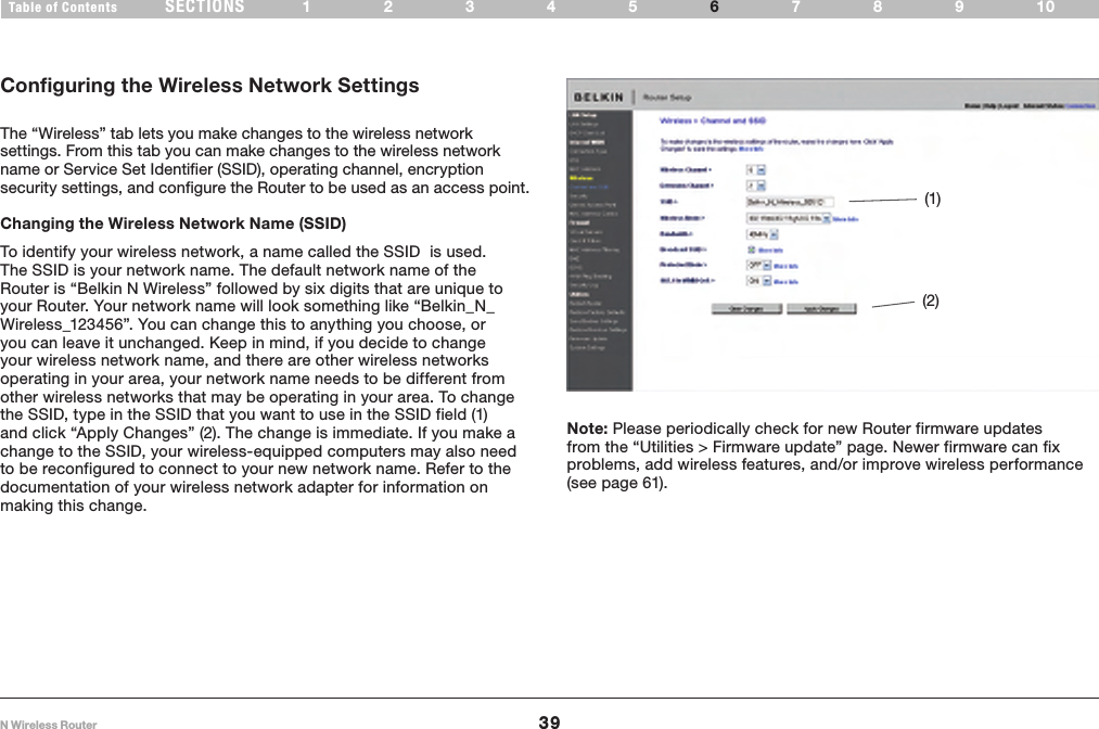
![33N Wireless RouterSECTIONSTable of Contents 1234 6789105ALTERNATE SETUP METHOD Setting your Connection Type if You Are a Telstra® BigPond/OptusNet Cable User6. Disconnect after X….The “Disconnect” feature is used to automatically disconnect the Router from your ISP when there is no activity for a specified period of time. For instance, placing a check mark next to this option and entering “5” into the minute field will cause the Router to disconnect from the Internet after five minutes of no Internet activity. This option should be used if you pay for your Internet service by the minute.[Australia Only] Follow the on-screen steps and click “Apply Changes” to complete your setup.](https://usermanual.wiki/Belkin/F5D8236V3.Manual-Part-2/User-Guide-1080982-Page-9.png)