Belkin F5D8236V3 N Wireless Router User Manual Manual Part 2
Belkin International, Inc. N Wireless Router Manual Part 2
Belkin >
Contents
- 1. Manual part 1
- 2. Manual Part 2
- 3. Manual Part 3
- 4. Manual Part 4
Manual Part 2
25
G Wireless Router
SECTIONSTable of Contents 123 56789104
ALTERNATE SETUP METHOD
Step 1: Hardware Connections – Follow the Quick Installation Guide
See the QIG or Step 1: Hardware Connections from the previous section.
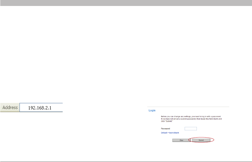
Logging into the Router
You will see the Router’s home page in your browser window. The home
page is visible to any user who wants to see it. To make any changes
to the Router’s settings, you have to log in. Clicking the “Login” button
or clicking on any one of the links on the home page will take you to the
login screen. The Router ships with no password entered. In the login
screen, leave the password blank and click the “Submit” button to log in.
Step 3: Configuring the Router Using the
Web-Based Advanced User Interface
Using your Internet browser, you can access the Router’s Web-Based
Advanced User Interface. In your browser, type “192.168.2.1” (do not type
in anything else such as “http://” or “www”). Then press the “Enter” key.
Step 2: Set your Computer’s Network Settings to Work with a DHCP Server
See the section in this User Manual called “Manually Configuring Network Settings” for directions.
26
N Wireless Router
SECTIONSTable of Contents 1234 6789105
ALTERNATE SETUP METHOD
Logging out of the Router
One computer at a time can log into the Router for the purposes of
making changes to the settings of the Router. Once a user has logged in
to make changes, there are two ways that the computer can be logged
out. Clicking the “Logout” button will log the computer out. The second
method is automatic. The login will time out after a specified period of
time. The default login time-out is 10 minutes. This can be changed from
one to 99 minutes. For more information, see the section in this manual
titled “Changing the Login Time-Out Setting”.
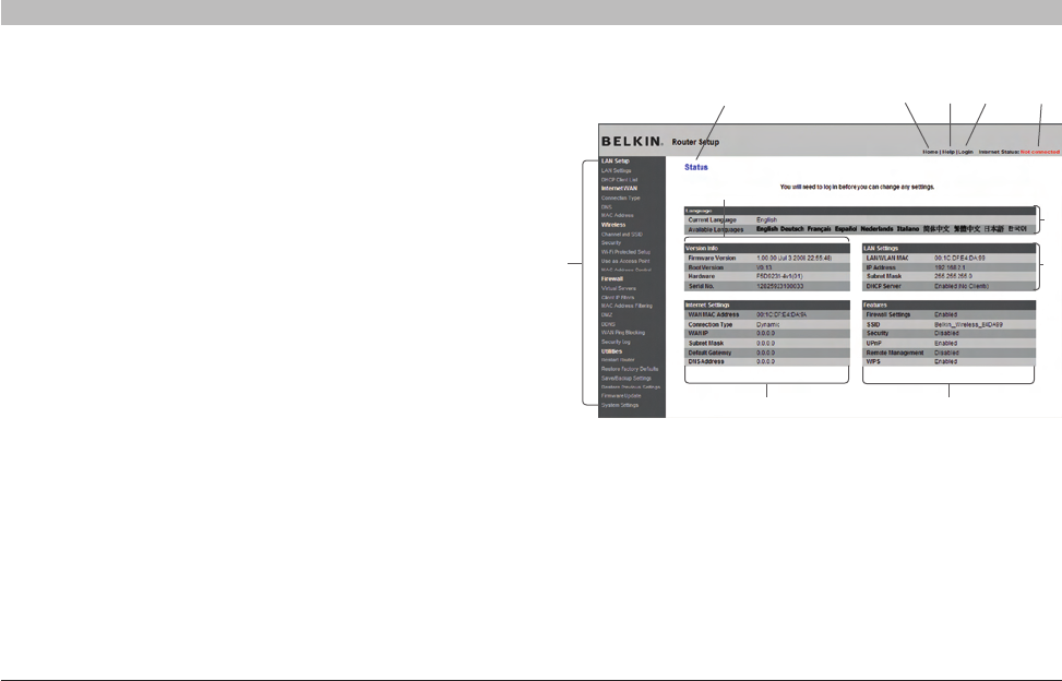
Understanding the Web-Based Advanced User Interface
The home page is the first page you will see when you access the
Advanced User Interface (UI). The home page shows you a quick view
of the Router’s status and settings. All advanced setup pages can be
reached from this page.
(11) (3) (4) (5)
(10)
(6)
(1)
(2)
(7)
(9)
(8)

27
N Wireless Router
SECTIONSTable of Contents 1234 6789105
ALTERNATE SETUP METHOD
1. Quick-Navigation Links
You can go directly to any of the Router’s advanced UI pages by clicking
directly on these links. The links are divided into logical categories
and grouped by tabs to make finding a particular setting easier to find.
Clicking on the header of each tab will show you a short description of
the tab’s function.
2. Home Button
The home button is available in every page of the UI. Pressing this
button will take you back to the home page.
3. Help Button
The “Help” button gives you access to the Router’s help pages. Help
is also available on many pages by clicking “more info” next to certain
sections of each page.
4. Login/Logout Button
This button enables you to log in and out of the Router with the press of
one button. When you are logged into the Router, this button will change
to read “Logout”. Logging into the Router will take you to a separate
login page where you will need to enter a password. When you are
logged into the Router, you can make changes to the settings. When you
are finished making changes, you can log out of the Router by clicking
the “Logout” button. For more information about logging into the Router,
see the section called “Logging into the Router”.
5. Internet-Status Indicators
This indicator is visible in all pages of the Router, indicating the
connection status of the Router. When the indicator says “Connected”
in blue, the Router is connected to the Internet. When the Router is not
connected to the Internet, the indicator will read “Not Connected” in
RED. The indicator is automatically updated when you make changes to
the settings of the Router.
6. Language
Shows the active language for the Advanced User Interface. Select a
desirable language by clicking one of the available languages.
7. Version Info
Shows the firmware version, boot-code version, hardware version, and
serial number of the Router.
8. LAN Settings
Shows you the settings of the Local Area Network (LAN) side of the
Router. Changes can be made to the settings by clicking on any one
of the links (IP Address, Subnet Mask, DHCP Server) or by clicking the
“LAN” quick-navigation link on the left side of the screen.
28
N Wireless Router
SECTIONSTable of Contents 1234 6789105
ALTERNATE SETUP METHOD
9. Internet Settings
Shows the settings of the Internet/WAN side of the Router that
connects to the Internet. Changes to any of these settings can be made
by clicking on the links or by clicking on the “Internet/WAN” quick-
navigation link on the left side of the screen.
10. Features
Shows the status of the Router’s firewall, and wireless features.
Changes can be made to the settings by clicking on any one of the links
or by clicking the quick-navigation links on the left side of the screen.
11. Page Name
The page you are on can be identified by this name. This User Manual
will sometimes refer to pages by name. For instance “LAN > LAN
Settings” refers to the “LAN Settings” page.
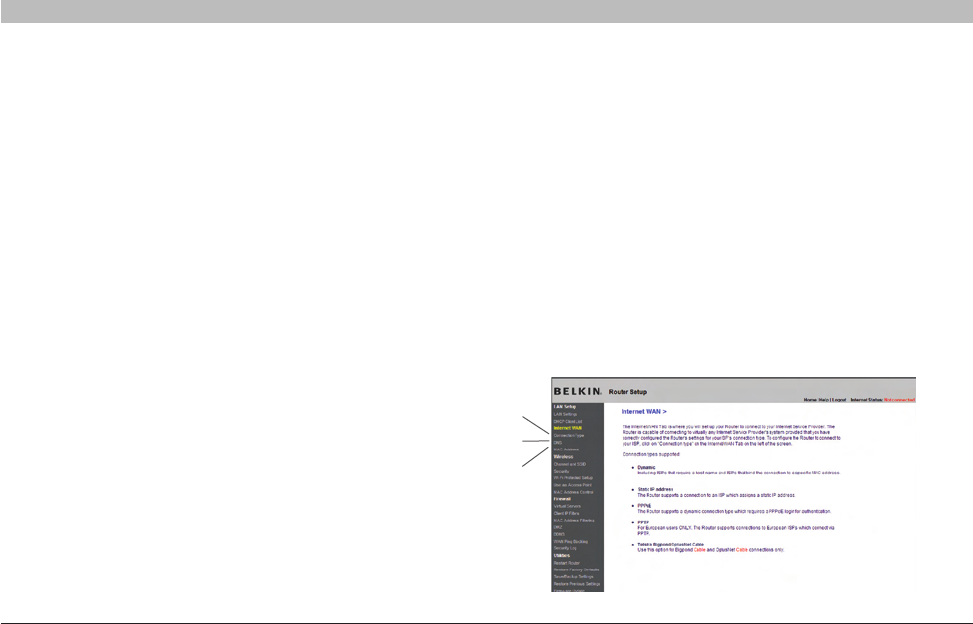
Step 4: Configuring your Router for Connection
to your Internet Service Provider (ISP)
The “Internet/WAN” tab is where you will set up your Router to connect
to your Internet Service Provider (ISP). The Router is capable of
connecting to virtually any ISP’s system provided you have correctly
configured the Router’s settings for your ISP’s connection type. Your ISP
connection settings are provided to you by your ISP. To configure the
Router with the settings that your ISP gave you, click “Connection Type”
(A) on the left side of the screen. Select the connection type you use. If
your ISP gave you DNS settings, clicking “DNS” (B) allows you to enter
DNS address entries for ISPs that require specific settings. Clicking
“MAC Address” (C) will let you clone your computer’s MAC address or
type in a specific WAN MAC address, if required by your ISP. When you
have finished making settings, the “Internet Status” indicator will read
“connection OK” if your Router is set up properly.
(A)
(B)
(C)
29
N Wireless Router
SECTIONSTable of Contents 1234 6789105
ALTERNATE SETUP METHOD
(2)
(1)
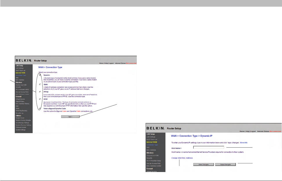
Setting your Connection Type
From the “Connection Type” page, you can select the type of connection
you use. Select the type of connection you use by clicking the button (1)
next to your connection type and then clicking “Next” (2).
Setting your Internet Service Provider (ISP)
Connection Type to Dynamic IP
A dynamic connection type is the most common connection type found
with cable modems. Setting the connection type to “dynamic” in many
cases is enough to complete the connection to your ISP. Some dynamic
connection types may require a host name. You can enter your host
name in the space provided if you were assigned one. Your host name is
assigned by your ISP. Some dynamic connections may require that you
clone the MAC address of the PC that was originally connected to the
modem.
1. Host Name (1)
This space is provided to enter a host name that needs to be visible to
your ISP. Enter your host name here and click “Apply Changes” (3). If your
ISP did not assign you a host name, or you are not sure, leave this blank.
2. Change WAN MAC Address (2)
If your ISP requires a specific MAC address to connect to the service,
you can enter a specific MAC address or clone the current computer’s
MAC address through this link.
(2)
(1)
(3)
30
N Wireless Router
SECTIONSTable of Contents 1234 6789105
ALTERNATE SETUP METHOD
Setting your Internet Service Provider (ISP)
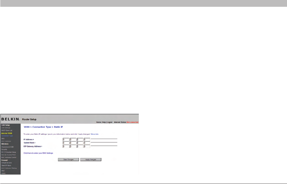
Connection Type to Static IP
A static IP address connection type is less common than other
connection types. If your ISP uses static IP addressing, you will
need your IP address, subnet mask, and ISP gateway address. This
information is available from your ISP or on the paperwork that your
ISP left with you. Type in your information, then click “Apply Changes”
(4). After you apply the changes, the Internet Status indicator will read
“Connected” if your Router is set up properly.
1. IP Address (1)
Provided by your ISP. Enter your IP address here.
2. Subnet Mask (2)
Provided by your ISP. Enter your subnet mask here.
3. ISP Gateway Address (3)
Provided by your ISP. Enter the ISP gateway address here.
(1)
(2)
(3)
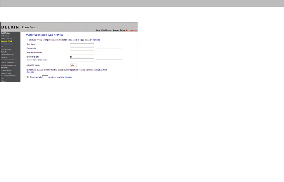
Setting your ISP Connection Type to PPPoE
Most DSL providers use PPPoE as the connection type. If you use a DSL
modem to connect to the Internet, your ISP may use PPPoE to log you
into the service. If you have an Internet connection in your home or small
office that doesn’t require a modem, you may also use PPPoE.
Your connection type is PPPoE if:
1) Your ISP gave you a user name and password,
which is required to connect to the Internet.
2) Your ISP gave you software such as WinPOET or
Enternet300 that you use to connect to the Internet.
3) You have to double-click on a desktop icon other
than your browser to get on the Internet.
31
N Wireless Router
SECTIONSTable of Contents 1234 6789105
ALTERNATE SETUP METHOD
(1)
(2)
(3)
(4)
(5)
1. User Name
This space is provided to type in your user name that was assigned by
your ISP.
2. Password
Type in your password and re-type it into the “Retype Password” box to
confirm it.
3. Service Name
A service name is rarely required by an ISP. If you are not sure if your
ISP requires a service name, leave this blank.
4. MTU
The MTU setting should never be changed unless your ISP gives you
a specific MTU setting. Making changes to the MTU setting can cause
problems with your Internet connection including disconnection from the
Internet, slow Internet access, and problems with Internet applications
working properly.
5. Disconnect after X minutes…
The “Disconnect” feature is used to automatically disconnect the Router
from your ISP when there is no activity for a specified period of time. For
instance, placing a check mark next to this option and entering “5” into
the minute field will cause the Router to disconnect from the Internet
after five minutes of no Internet activity. This option should be used if
you pay for your Internet service by the minute.
32
N Wireless Router
SECTIONSTable of Contents 1234 6789105
ALTERNATE SETUP METHOD
(1)
(2)
(4)
(5)
(3)
(6)
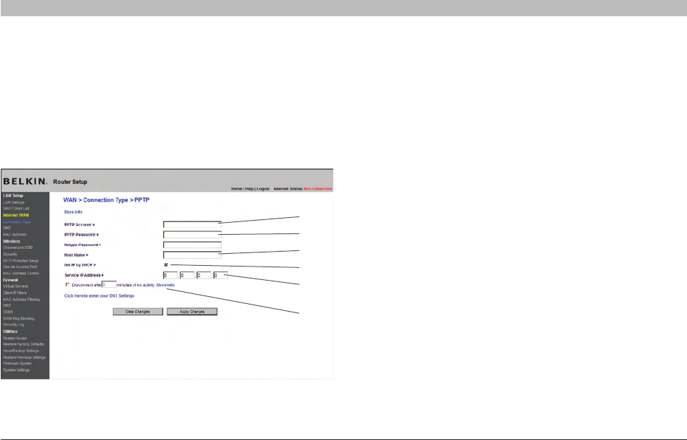
Setting your Internet Service Provider (ISP) Connection
Type to Point-to-Point Tunneling Protocol (PPTP)
[European Countries Only] Some ISPs require a connection using PPTP
protocol, a type of connection most common in European countries.
This sets up a direct connection to the ISP’s system. Type in the
information provided by your ISP in the space provided. When you have
finished, click “Apply Changes” (9). After you apply the changes, the
Internet Status indicator will read “connection OK” if your Router is set
up properly.
1. PPTP Account
Provided by your ISP. Enter your PPTP account name here.
2. PPTP Password
Type in your password and retype it into the “Retype Password” box to
confirm it.
3. Host Name
Provided by your ISP. Enter your host name here.
4. Get IP by DHCP
If your ISP provided you with a specific IP address, uncheck this box
and enter your IP address, subnet mask, and default gateway in the
fields that appear.
5. Service IP Address
Provided by your ISP. Enter your service IP address here.
33
N Wireless Router
SECTIONSTable of Contents 1234 6789105
ALTERNATE SETUP METHOD
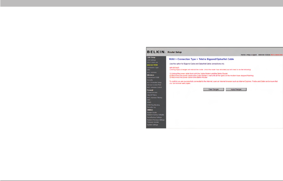
Setting your Connection Type if You Are a Telstra®
BigPond/OptusNet Cable User
6. Disconnect after X….
The “Disconnect” feature is used to automatically disconnect the Router
from your ISP when there is no activity for a specified period of time. For
instance, placing a check mark next to this option and entering “5” into
the minute field will cause the Router to disconnect from the Internet
after five minutes of no Internet activity. This option should be used if
you pay for your Internet service by the minute.
[Australia Only] Follow the on-screen steps and click “Apply Changes”
to complete your setup.
34
N Wireless Router
SECTIONSTable of Contents 1234 6789105
ALTERNATE SETUP METHOD
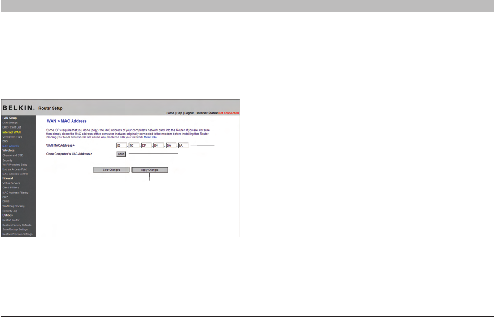
Configuring your WAN Media Access Controller (MAC) Address
All network components including cards, adapters, and routers, have
a unique “serial number” called a MAC address. Your Internet Service
Provider (ISP) may record the MAC address of your computer’s adapter
and only let that particular computer connect to the Internet service.
When you install the Router, its own MAC address will be “seen” by the
ISP and may cause the connection not to work. Belkin has provided
the ability to clone (copy) the MAC address of the computer into the
Router. This MAC address, in turn, will be seen by the ISP’s system as
the original MAC address and will allow the connection to work. If you
are not sure whether your ISP needs to see the original MAC address,
simply clone the MAC address of the computer that was originally
connected to the modem. Cloning the address will not cause any
problems with your network.
Cloning your MAC Address
To clone your MAC address, make sure that you are using the computer
that was ORIGINALLY CONNECTED to your modem before the Router
was installed. Click the “Clone” button (1). Click “Apply Changes” (3).
Your MAC address is now cloned to the Router.
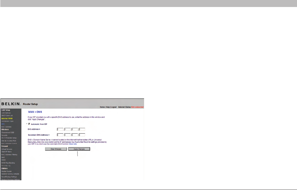
Setting Custom Domain Name Server (DNS) Settings
A “Domain Name Server” is a server located on the Internet that
translates Universal Resource Locaters (URLs) like “www.belkin.com” to
IP addresses. Many Internet Service Providers (ISPs) do not require you
to enter this information into the Router. The “Automatic from ISP” box (1)
should be checked if your ISP did not give you a specific DNS address.
If you are using a static IP connection type, then you may need to enter a
specific DNS address and secondary DNS address for your connection
to work properly. If your connection type is dynamic or PPPoE, it is likely
that you do not have to enter a DNS address. Leave the “Automatic
from ISP” box checked. To enter the DNS address settings, uncheck
the “Automatic from ISP” box and enter your DNS entries in the spaces
provided. Click “Apply Changes” (2) to save the settings.
(1)
(2)
35
N Wireless Router
SECTIONSTable of Contents 1234 6789105
ALTERNATE SETUP METHOD
Entering a Specific MAC Address
In certain circumstances you may need a specific WAN MAC address.
You can manually enter one in the “MAC Address” page. Type in a MAC
address in the spaces provided (2) and click “Apply Changes” (3) to save
the changes. The Router’s WAN MAC address will now be changed to
the MAC address you specified.
(1)
(3)
(2)
36
N Wireless Router
SECTIONSTable of Contents 12345 78910
USING THE WEB-BASED ADVANCED USER INTERFACE
6
Using your Internet browser, you can access the Router’s Web-Based
Advanced User Interface. In your browser, type “192.168.2.1” (do
not type in anything else such as “http://” or “www”) then press the
“Enter” key.
You will see the Router’s home page in your browser window.
(1)
(2)
(3)
Viewing the LAN Settings
Clicking on the header of the LAN tab (1) will take you to the LAN tab’s
header page. A quick description of the functions can be found here. To
view the settings or make changes to any of the LAN settings, click on
“LAN Settings” (2) or to view the list of connected computers, click on
“DHCP client list” (3).
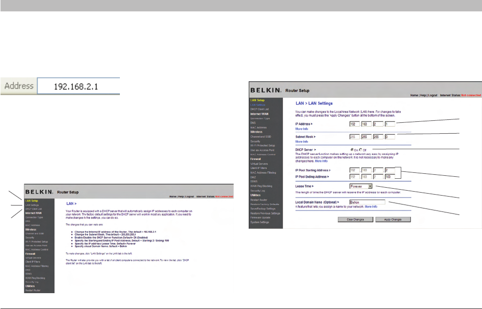
Changing LAN Settings
All settings for the internal LAN setup of the Router can be viewed and
changed here.
(1)
(2)
(4)
(5)
(6)
(3)

37
N Wireless Router
SECTIONSTable of Contents 12345 789106
USING THE WEB-BASED ADVANCED USER INTERFACE
1. IP Address
The “IP address” is the internal IP address of the Router. The default IP
address is “192.168.2.1”. To access the advanced setup interface, type
this IP address into the address bar of your browser. This address can
be changed if needed. To change the IP address, type in the new IP
address and click “Apply Changes”. The IP address you choose should
be a non-routable IP. Examples of a non-routable IP are:
192.168.x.x (where x is anything between 1 and 254)
10.x.x.x (where x is anything between 1 and 254)
172.y.x.x (where x is anything between 1 and 254 and y is anything
between 16 and 31)
2. Subnet Mask
There is no need to change the subnet mask. This is a unique, advanced
feature of your Belkin Router. It is possible to change the subnet mask
if necessary; however, do NOT make changes to the subnet mask
unless you have a specific reason to do so. The default setting is
“255.255.255.0”.
3. DHCP Server
The DHCP server function makes setting up a network very easy by
assigning IP addresses to each computer on the network automatically.
The default setting is “On”. The DHCP server can be turned OFF if
necessary; however, in order to do so you must manually set a static
IP address for each computer on your network. To turn off the DHCP
server, select “Off” and click “Apply Changes”.
4. IP Pool
The range of IP addresses set aside for dynamic assignment to the
computers on your network. The default is 2–100 (99 computers). If you
want to change this number, you can do so by entering a new starting
and ending IP address and clicking on “Apply Changes”. The DHCP
server can assign 100 IP addresses automatically. This means that
you cannot specify an IP address pool larger than 100 computers. For
example, starting at 50 means you have to end at 150 or lower so as not
to exceed the 100-client limit. The starting IP address must be lower in
number than the ending IP address.
38
N Wireless Router
SECTIONSTable of Contents 12345 789106
USING THE WEB-BASED ADVANCED USER INTERFACE
5. Lease Time
The length of time the DHCP server will reserve the IP address for each
computer. We recommend that you leave the lease time set to “Forever”.
The default setting is “Forever”, meaning that any time a computer is
assigned an IP address by the DHCP server, the IP address will not
change for that particular computer. Setting lease times for shorter
intervals such as one day or one hour frees IP addresses after the
specified period of time. This also means that a particular computer’s
IP address may change over time. If you have set any of the other
advanced features of the Router such as DMZ or client IP filters, these
are dependent on the IP address. For this reason, you will not want the
IP address to change.
6. Local Domain Name
The default setting is “Belkin”. You can set a local domain name
(network name) for your network. There is no need to change this setting
unless you have a specific advanced need to do so. You can name the
network anything you want such as “MY NETWORK”.
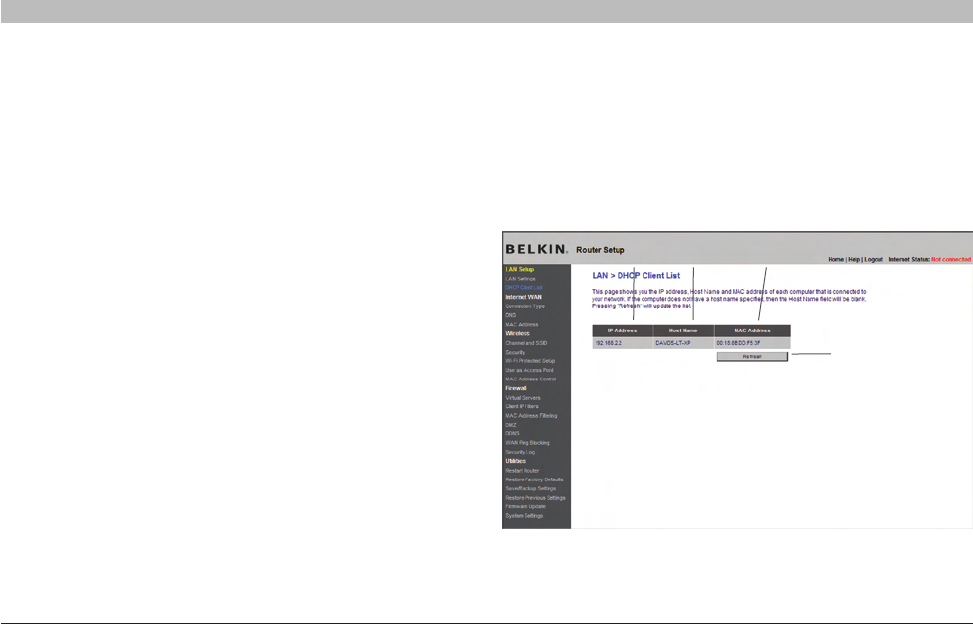
Viewing the DHCP Client List Page
You can view a list of the computers (known as clients), which are
connected to your network. You are able to view the IP address (1) of the
computer, the host name (2) (if the computer has been assigned one),
and the MAC address (3) of the computer’s network interface card (NIC).
Pressing the “Refresh” (4) button will update the list. If there have been
any changes, the list will be updated.
(1) (2) (3)
(4)
39
N Wireless Router
SECTIONSTable of Contents 12345 789106
USING THE WEB-BASED ADVANCED USER INTERFACE
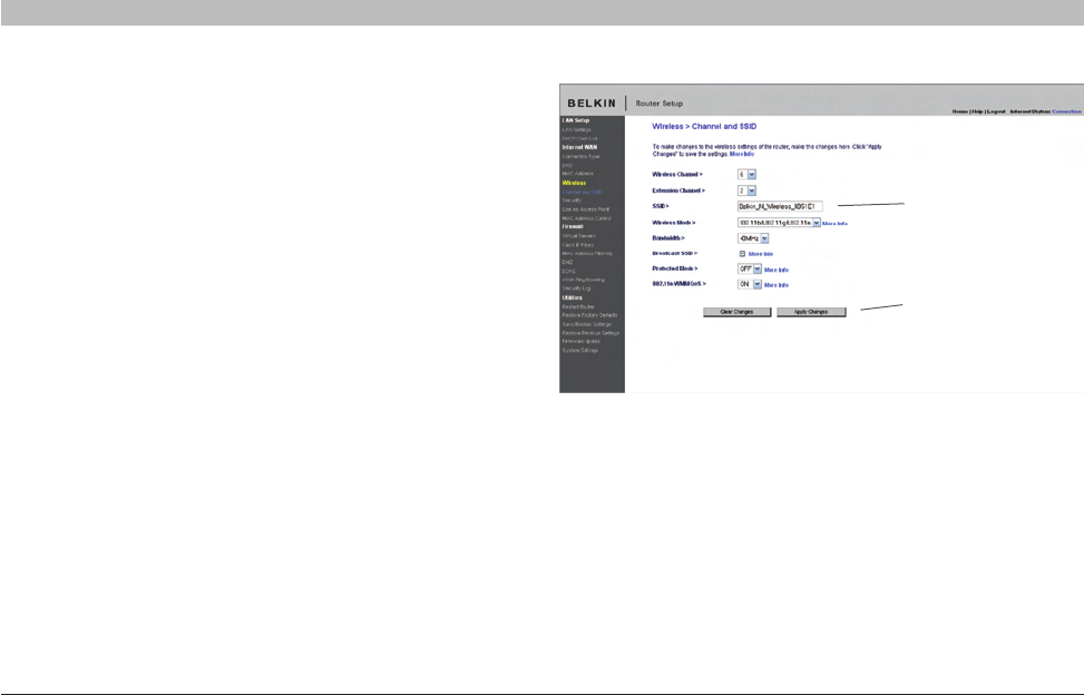
Configuring the Wireless Network Settings
The “Wireless” tab lets you make changes to the wireless network
settings. From this tab you can make changes to the wireless network
name or Service Set Identifier (SSID), operating channel, encryption
security settings, and configure the Router to be used as an access point.
Changing the Wireless Network Name (SSID)
To identify your wireless network, a name called the SSID is used.
The SSID is your network name. The default network name of the
Router is “Belkin N Wireless” followed by six digits that are unique to
your Router. Your network name will look something like “Belkin_N_
Wireless_123456”. You can change this to anything you choose, or
you can leave it unchanged. Keep in mind, if you decide to change
your wireless network name, and there are other wireless networks
operating in your area, your network name needs to be different from
other wireless networks that may be operating in your area. To change
the SSID, type in the SSID that you want to use in the SSID field (1)
and click “Apply Changes” (2). The change is immediate. If you make a
change to the SSID, your wireless-equipped computers may also need
to be reconfigured to connect to your new network name. Refer to the
documentation of your wireless network adapter for information on
making this change.
(1)
(2)
Note: Please periodically check for new Router firmware updates
from the “Utilities > Firmware update” page. Newer firmware can fix
problems, add wireless features, and/or improve wireless performance
(see page 61).

40
N Wireless Router
SECTIONSTable of Contents 12345 789106
USING THE WEB-BASED ADVANCED USER INTERFACE
Changing the Wireless Channel
There are a number of operating channels from which you can choose—
in the United States, there are 11 and in the United Kingdom (and most
of Europe), there are 13. In a small number of other countries, there are
other channel requirements. Your Router is configured to operate on the
proper channels for the country in which you reside. The channel can
be changed if needed. If there are other wireless networks operating in
your area, your network should be set to operate on a channel that is
different than the other wireless networks.
Extension Channel
The IEEE 802.11n draft specification allows the use of a secondary
channel to double the bandwidth (see “Using the Bandwidth Switch”
below). An appropriate extension channel will be displayed when
operating in 40MHz mode (see “Using the Wireless Mode Switch”
below). The channel can be changed if needed.
Using the Wireless Mode Switch
This switch allows you to set the Router’s wireless modes. There are
several modes.
Note: Some modes may require firmware updates to be enabled.
1) Off
This mode will turn OFF the Router’s access point, so no wireless
devices can join the network. Turning off the wireless function of your
Router is a great way to secure your network when you are away from
home for a long period of time, or don’t want to use the wireless feature
of the Router at a certain time.
2) 802.11g only
Setting the Router to this mode will allow only 802.11g-compliant
devices to join the network, keeping out any slower 802.11b devices.
3) 802.11b+g+n
Setting the Router to this mode will allow 802.11b-, 802.11g-, and
802.11n-compliant devices to join the network.
4) 802.11n only
Setting the Router to this mode will allow only N/draft 802.11n-compliant
devices to join the network, keeping out 802.11g and 802.11b devices.
41
N Wireless Router
SECTIONSTable of Contents 12345 789106
USING THE WEB-BASED ADVANCED USER INTERFACE
Using the Bandwidth Switch
This switch allows you to set the Router’s wireless bandwidth modes.
There are several modes available:
1) 20MHz only
Setting the Router to this mode allows only 20MHz operation. This mode
is compatible with N, draft 802.11n-, 802.11g-, and 802.11b-compliant
devices, but will limit N, draft 802.11n-compliant devices’ bandwidth by
half. Reducing bandwidth to 20MHz-only operation might solve some
wireless problems.
2) 20MHz/40MHz Auto
Setting the Router to this mode allows it to switch automatically between
20MHz and 40MHz operation. This mode enables 40MHz operation, to
maximize speed for N, draft 802.11n-compliant devices when conditions
permit. When a legacy 802.11g access point is presented and occupies
an adjacent secondary channel, the Router automatically reverts to
20MHz operation to maximize compatibility. We recommend using this
as the default mode.

42
N Wireless Router
SECTIONSTable of Contents 12345 789106
USING THE WEB-BASED ADVANCED USER INTERFACE
Using the Broadcast SSID Feature
Note: This advanced feature should be employed by advanced
users only.
For security, you can choose not to broadcast your network’s SSID.
Doing so will keep your network name hidden from computers that
are scanning for the presence of wireless networks. To turn off the
broadcast of the SSID, remove the check mark from the box next to
“Broadcast SSID”, and then click “Apply Changes”. The change is
immediate. Each computer now needs to be set to connect to your
specific SSID; an SSID of “ANY” will no longer be accepted. Refer to
the documentation of your wireless network adapter for information on
making this change.
Protected Mode Switch
Protected mode ensures proper operation of N, draft 802.11n-compliant
devices on your wireless network when 802.11g or 802.11b devices
are present or when there is heavy 802.11g or 802.11b traffic in the
operating environment. Use protected mode if your network consists of
a mix of Belkin N Wireless Cards and 802.11g or 802.11b cards on your
network. If you are in an environment that includes little to no 802.11g
or 802.11b wireless network traffic, you will achieve the best N wireless
performance with protected mode OFF. Conversely, in an environment
with HEAVY 802.11g or 802.11b traffic or interference, you will achieve
the best N wireless performance with protected mode ON. This will
ensure N wireless performance is not affected.
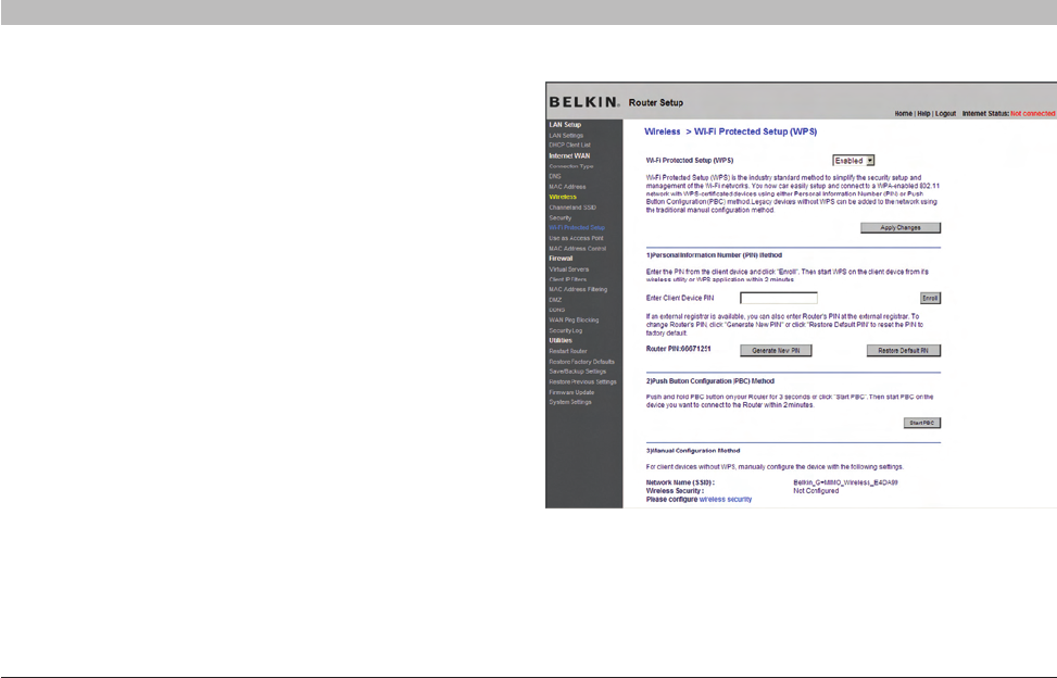
Changing the Wireless Security Settings
Your N Wireless Router is equipped with the latest security standard
called Wi-Fi Protected Access™ 2 (WPA2™) and the legacy security
standard called Wired Equivalent Privacy (WEP). Your Router also
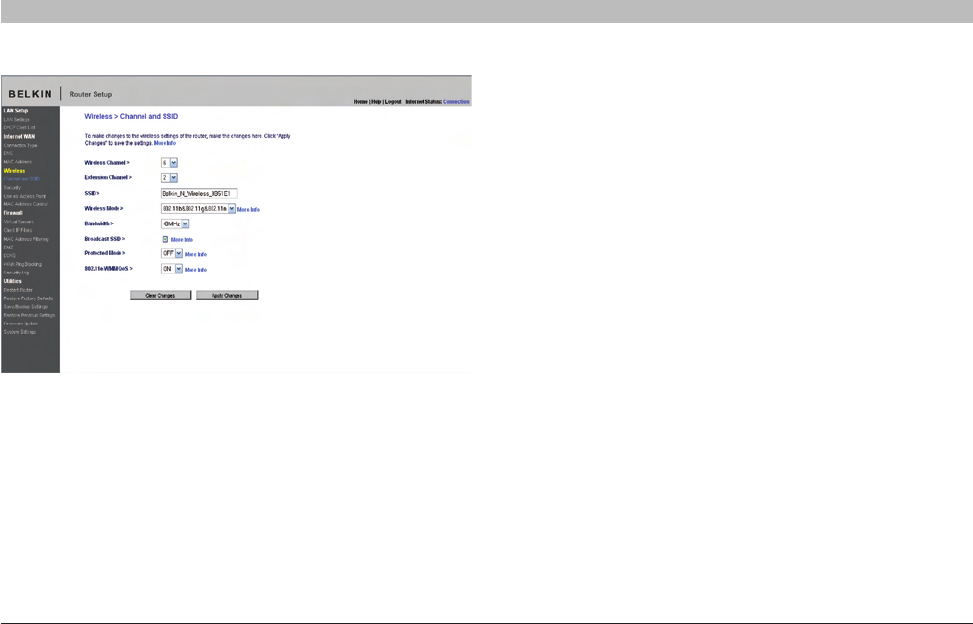
supports the Wi-Fi Protected Setup™ (WPS) specification, which
simplifies the setup of a wireless network. WPS uses familiar
methodologies, such as typing in a Personal Identification Number (PIN)
or pushing a button, to enable users to automatically configure network
names and strong WPA™/WPA2 data encryption and authentication. By
default, wireless security is disabled. To enable security, you will need
to determine which standard you want to use. To access the security
settings, click “Security” on the “Wireless” tab.
802.11e/WMM QoS Switch
Allows you to turn ON or OFF wireless QoS.
43
N Wireless Router
SECTIONSTable of Contents 12345 789106
USING THE WEB-BASED ADVANCED USER INTERFACE
Using Wi-Fi Protected Setup
WPS recommends WPA/WPA2 (described on page 45) for encryption. It
does not provide additional security, but rather, standardizes the method
for securing your wireless network. You may use either the Push Button
Configuration (PBC) method or PIN method to allow a device access to
your wireless network. Conceptually, the two methods work as follows:
PBC: Push and hold the WPS button located on the front of your Router
for three seconds. Then, initiate the WPS procedure on the client
device within two minutes. Refer to your client’s documentation on this
procedure. Pushing the PBC button will automatically enable WPS. The
client has now been securely added to your wireless network.
PIN: The client device has a PIN number (either four or eight digits) that
is associated with WPS. Enable WPS through the screen illustrated
below. Enter the client’s PIN into the Router’s internal registrar
(accessed through this screen). The client will be automatically enrolled
into your wireless network within two minutes.

44
N Wireless Router
SECTIONSTable of Contents 12345 789106
USING THE WEB-BASED ADVANCED USER INTERFACE
1. Wi-Fi Protected Setup (WPS): Enabled or Disabled.
2. Personal Identification Number (PIN) Method: In this method,
a wireless client wishing to access your network must supply an
8-digit PIN to the Router. After clicking “Enroll”, you must start the
WPS handshaking procedure from the client within two minutes.
3. Router PIN: If an external registrar is available, you may enter in the
Router’s PIN to the registrar. Click “Generate New PIN” to change
the PIN from the default value. Click “Restore Default PIN” to reset
the PIN value.
4. Push Button Configuration (PBC) Method: PBC is an alternate
method to connect to a WPS network. Push the PBC button
located on the back of the Router for three seconds, and
then initiate the PBC on the client device. Alternatively,
push the “Start PBC” soft button to start this process.
5. Manual Configuration Method: This section lists the default
security settings to be set up if not using WPS.
WPA2 Requirements
IMPORTANT: In order to use WPA2 security, all your computers and
wireless client adapters must be upgraded with patches, driver, and client
utility software that supported WPA2. At the time of this User Manual’s
publication, a couple security patches are available, for free download,
from Microsoft®. These patches work only with the Windows XP operating
system. Other operating systems are not supported at this time.
For Windows XP computers that do not have Service Pack 2
(SP2), a file from Microsoft called “Windows XP Support Patch
for Wireless Protected Access (KB 826942)” is available for
free download at http://support.microsoft.com/kb/826942
For Windows XP with Service Pack 2, Microsoft has
released a free download to update the wireless client
components to support WPA2 (KB971021). The update is
available from: http://support.microsoft.com/kb/917021
IMPORTANT: You also need to ensure that all your wireless client
cards/adapters support WPA2, and that you have downloaded and
installed the latest driver. Most of the Belkin wireless cards have
driver updates available for download from the Belkin support site:
www.belkin.com/networking.
45
N Wireless Router
SECTIONSTable of Contents 12345 789106
USING THE WEB-BASED ADVANCED USER INTERFACE
Setting WPA/WPA2-Personal (PSK)
1. After you’ve set up your Router, go to the “Security”
page under “Wireless” and select “WPA/WPA2-Personal
(PSK)” from the “Security Mode” drop-down menu.
2. For “Authentication”, select “WPA-PSK”, “WPA2-PSK”,
or “WPA-PSK + WPA2-PSK”. This setting will have to be
identical on the wireless clients that you set up. “WPA-
PSK + WPA2-PSK” mode will allow the Router to support
clients running either WPA or WPA2 security.
3. Enter your pre-shared key (PSK). This can be from eight to
63 characters and can be letters, numbers, or symbols. This
same key must be used on all of the wireless clients that you
set up. For example, your PSK might be something like: “Smith
family network key”. Click “Apply Changes” to finish. You
must now set all wireless clients to match these settings.
IMPORTANT: Make sure your wireless computers are updated to
work with WPA or WPA2, and have the correct settings to get proper
connection to the Router.
46
N Wireless Router
SECTIONSTable of Contents 12345 789106
USING THE WEB-BASED ADVANCED USER INTERFACE
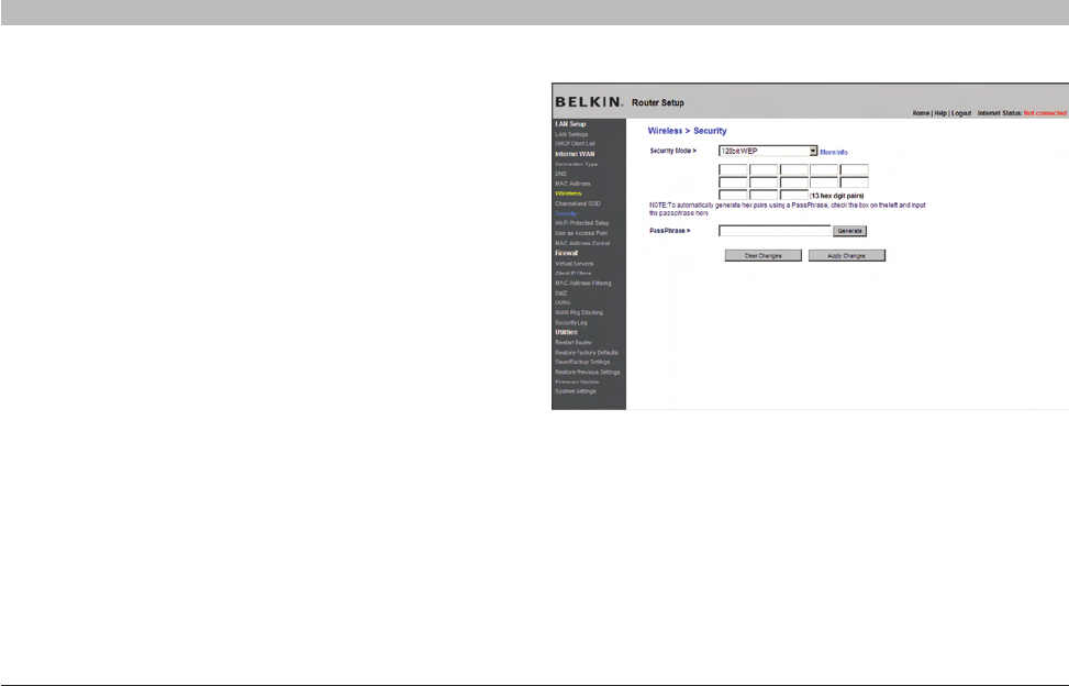
Setting WEP Encryption
Note to Mac users: The “Passphrase” option will not operate with
Apple® AirPort®. To configure encryption for your Mac computer, set the
encryption using the manual method described in the next section.
1. Select “128-bit WEP” or “64-bit WEP” from the drop-down menu.
2. After selecting your WEP encryption mode, you can enter you WEP
key manually by typing in the hex WEP key manually, or you can
type a passphrase in the “PassPhrase” field and click “Generate” to
create a WEP key from the passphrase. Click “Apply Changes” to
finish. You must now set all of your clients to match these settings.
3. Encryption in the Router is now set. Each of your computers on
your wireless network will now need to be configured with the
same passphrase. Refer to the documentation of your wireless
network adapter for information on making this change.
47
N Wireless Router
SECTIONSTable of Contents 12345 789106
USING THE WEB-BASED ADVANCED USER INTERFACE
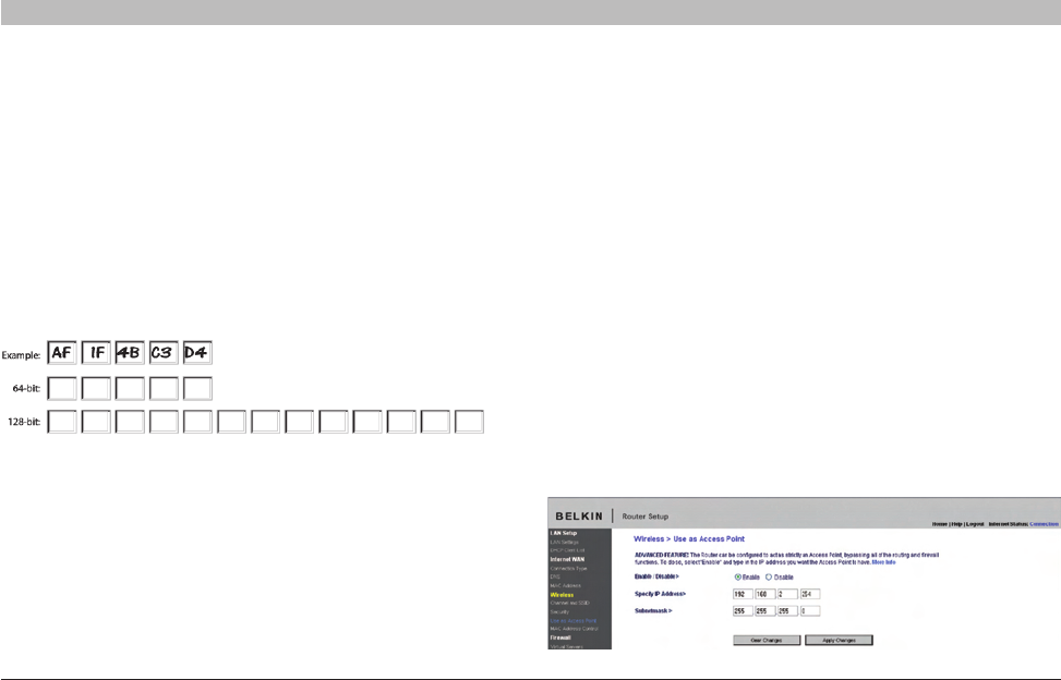
Using a Hexadecimal Key
A hexadecimal key is a mixture of numbers and letters from A–F and
0–9. 64-bit keys are 10 digits long and can be divided into five two-digit
numbers. 128-bit keys are 26 digits long and can be divided into 13
two-digit numbers.
For instance:
AF 0F 4B C3 D4 = 64-bit key
C3 03 0F AF 0F 4B B2 C3 D4 4B C3 D4 E7 = 128-bit key
In the boxes below, make up your key by writing in two characters
between A–F and 0–9. You will use this key to program the encryption
settings on your Router and your wireless computers.
Note to Mac users: Original Apple AirPort products support 64-bit
encryption only. Apple AirPort 2 products can support 64-bit or 128-bit
encryption. Please check your product to see which version you are
using. If you cannot configure your network with 128-bit encryption, try
64-bit encryption.
Using the Access Point Mode
Note: This advanced feature should be employed by advanced users
only. The Router can be configured to work as a wireless network
access point. Using this mode will defeat the NAT IP sharing feature and
DHCP server. In AP mode, the Router will need to be configured with an
IP address that is in the same subnet as the rest of the network that you
will bridge to. The default IP address is 192.168.2.254 and subnet mask
is 255.255.255.0. These can be customized for your need.
1. Enable the AP mode my selecting “Enable” in the “Use as Access
Point only” page. When you select this option, you will be able to
change the IP settings.
2. Set your IP settings to match your network. Click “Apply Changes”.
3. Connect a cable from the WAN port on the Router to your
existing network.
The Router is now acting as an access point. To access the Router
advanced user interface again, type the IP address you specified into
your browser’s navigation bar. You can set the encryption settings,
MAC address filtering, SSID, and channel normally.
48
N Wireless Router
SECTIONSTable of Contents 12345 789106
USING THE WEB-BASED ADVANCED USER INTERFACE
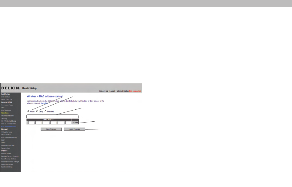
Setting MAC Address Control
The MAC address filter is a powerful security feature that allows you to
specify which computers are allowed on the wireless network. Note:
This list applies only to wireless computers. This list can be configured
so any computer attempting to access the wireless network that is not
specified in the filter list will be denied access. When you enable this
feature, you must enter the MAC address of each client (computer) to
which you want to allow network access. The “Block” feature lets you
turn on and off access to the network easily for any computer without
having to add and remove the computer’s MAC address from the list.
(a) (b)
(c)
(d)
(e)
Setting up an Allow Access List
1. Select the “Allow” radio button (a) to begin setting up a list
of computers allowed to connect to the wireless network.
2. Next, in the “MAC Address” field that is blank (c), type in the
MAC address of the wireless computer you want to be able
to access the wireless network, then click “<<Add” (d).
3. Continue to do this until all of the computers you want to add have
been entered.
4. Click “Apply Changes” (e) to finish.
49
N Wireless Router
SECTIONSTable of Contents 12345 789106
USING THE WEB-BASED ADVANCED USER INTERFACE
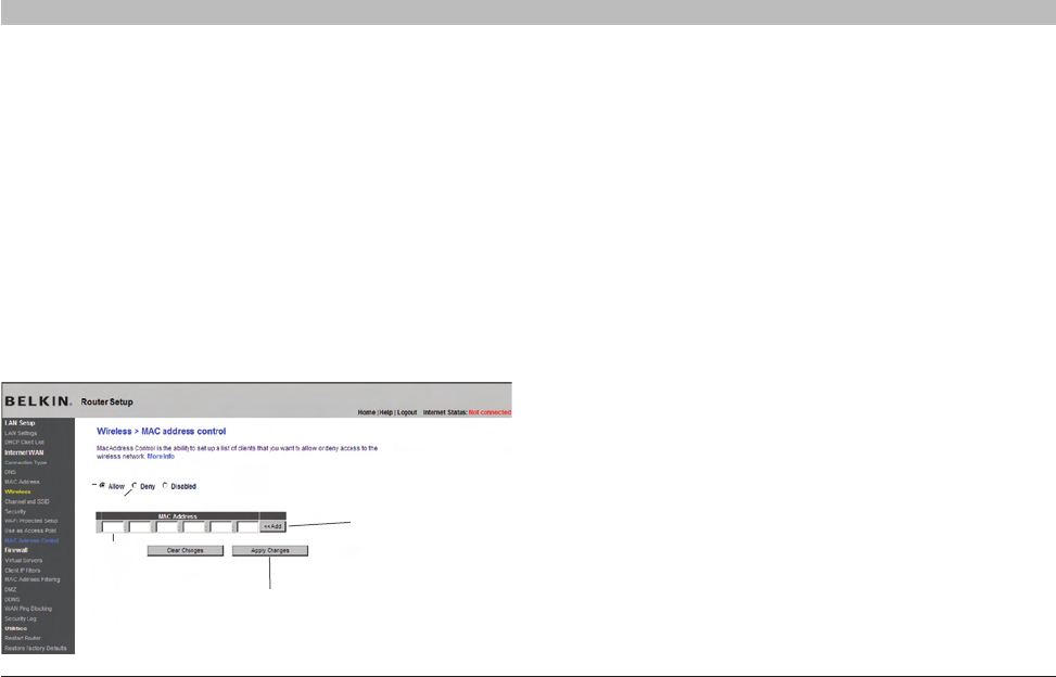
Setting up a Deny Access List
The “Deny Access” list lets you specify computers that you DO NOT
want to access the network. Any computer in the list will not be allowed
access to the wireless network. All others will.
1. Select the “Deny” radio button (b) to begin setting up a list of
computers to be denied access to the wireless network.
2. Next, in the “MAC Address” field that is blank (c), type in the
MAC address of the wireless computer you want to deny
access to the wireless network, then click “<<Add” (d).
(a)
(c)
(e)
(d)
(b)
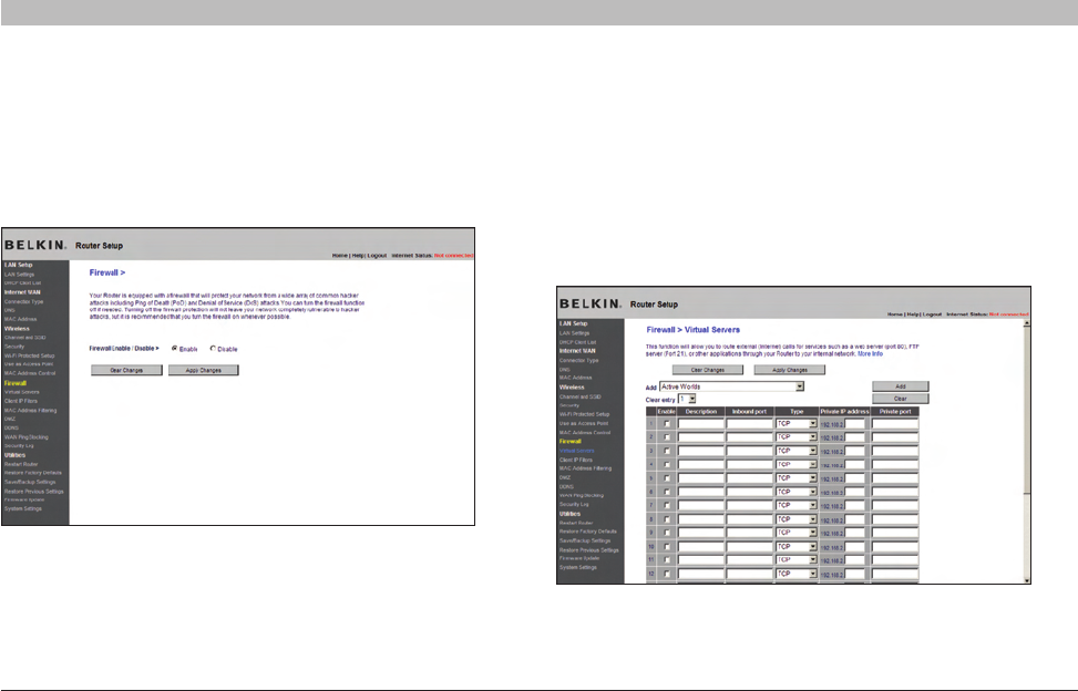
Configuring the Firewall
Your Router is equipped with a firewall that will protect your network
from a wide array of common hacker attacks including:
• IP Spoofing
• Land Attack Ping of Death (PoD)
• Denial of Service (DoS)
• IP with zero length
• Smurf Attack
• TCP Null Scan
• SYN flood
• UDP flooding
• Tear Drop Attack
• ICMP defect
• RIP defect
• Fragment flooding
3. Continue to do this until all of the computers you want to deny
access to have been entered.
4. Click “Apply Changes” (e) to finish.
50
N Wireless Router
SECTIONSTable of Contents 12345 789106
USING THE WEB-BASED ADVANCED USER INTERFACE
The firewall also masks common ports that are frequently used to
attack networks. These ports appear to be “stealth” meaning that for
all intents and purposes, they do not exist to a would-be hacker. You
can turn the firewall function off if needed; however, it is recommended
that you leave the firewall enabled. Disabling the firewall protection will
not leave your network completely vulnerable to hacker attacks, but it is
recommended that you leave the firewall enabled.
Configuring Internal Forwarding Settings
The Virtual Servers function will allow you to route external (Internet)
calls for services such as a web server (port 80), FTP server (Port 21), or
other applications through your Router to your internal network. Since
your internal computers are protected by a firewall, computers outside
your network (over the Internet) cannot get to them because they cannot
be “seen”. A list of common applications has been provided in case you
need to configure the Virtual Server function for a specific application.
If your application is not listed, you will need to contact the application
vendor to find out which port settings you need.