Belkin F5D8633-4A N Wireless Modem Router User Manual P75555uk F5D8633uk 4 v1000 man indd
Belkin International, Inc. N Wireless Modem Router P75555uk F5D8633uk 4 v1000 man indd
Belkin >
Contents
- 1. Manual 1
- 2. Manual 2
- 3. Manual 3
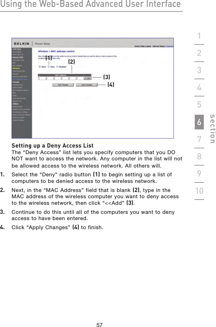
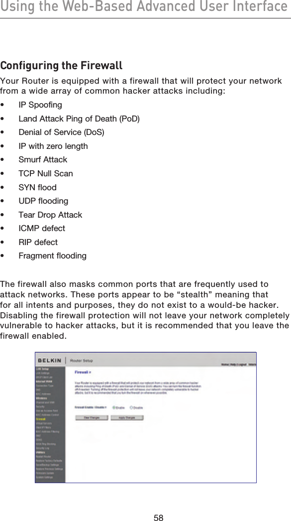
Manual 2