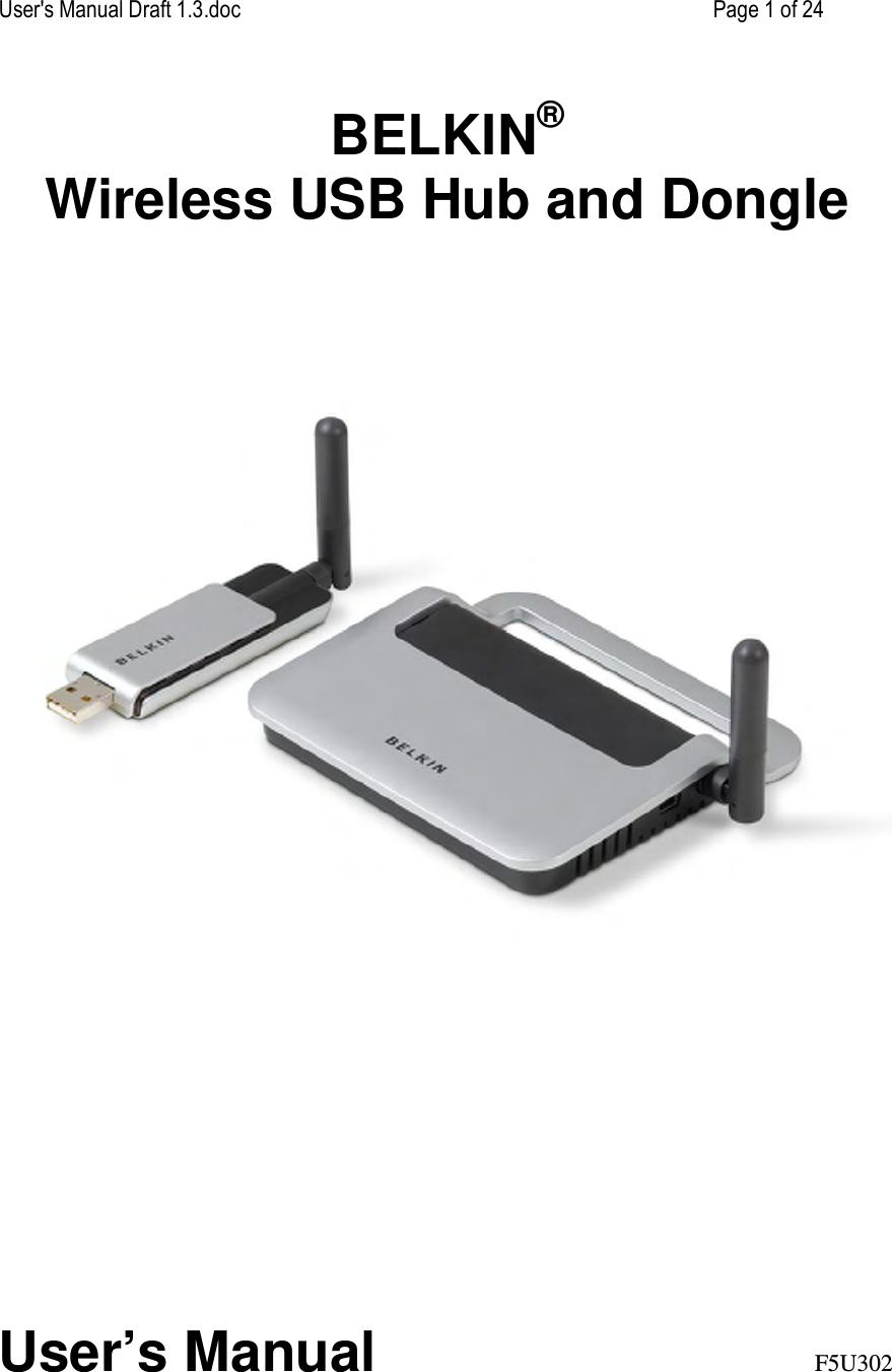
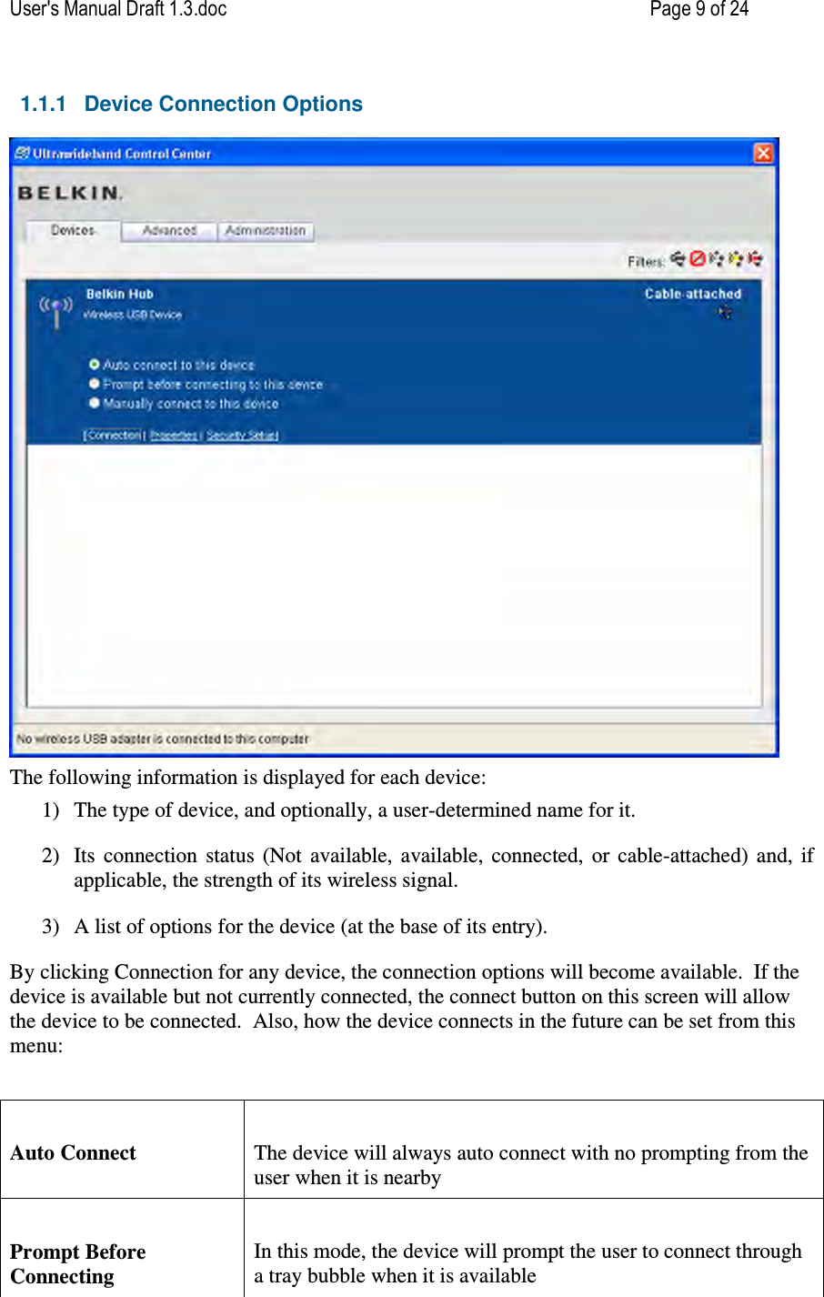
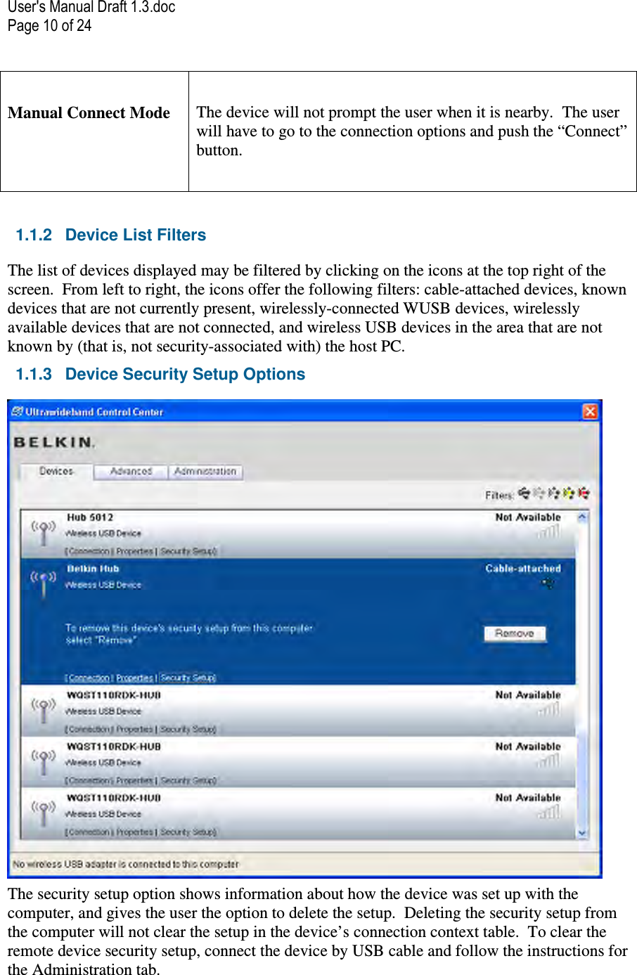
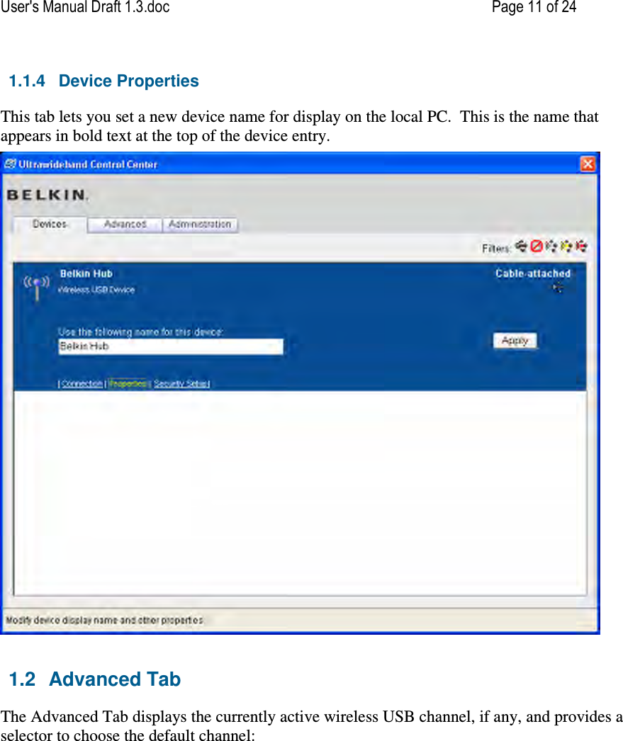
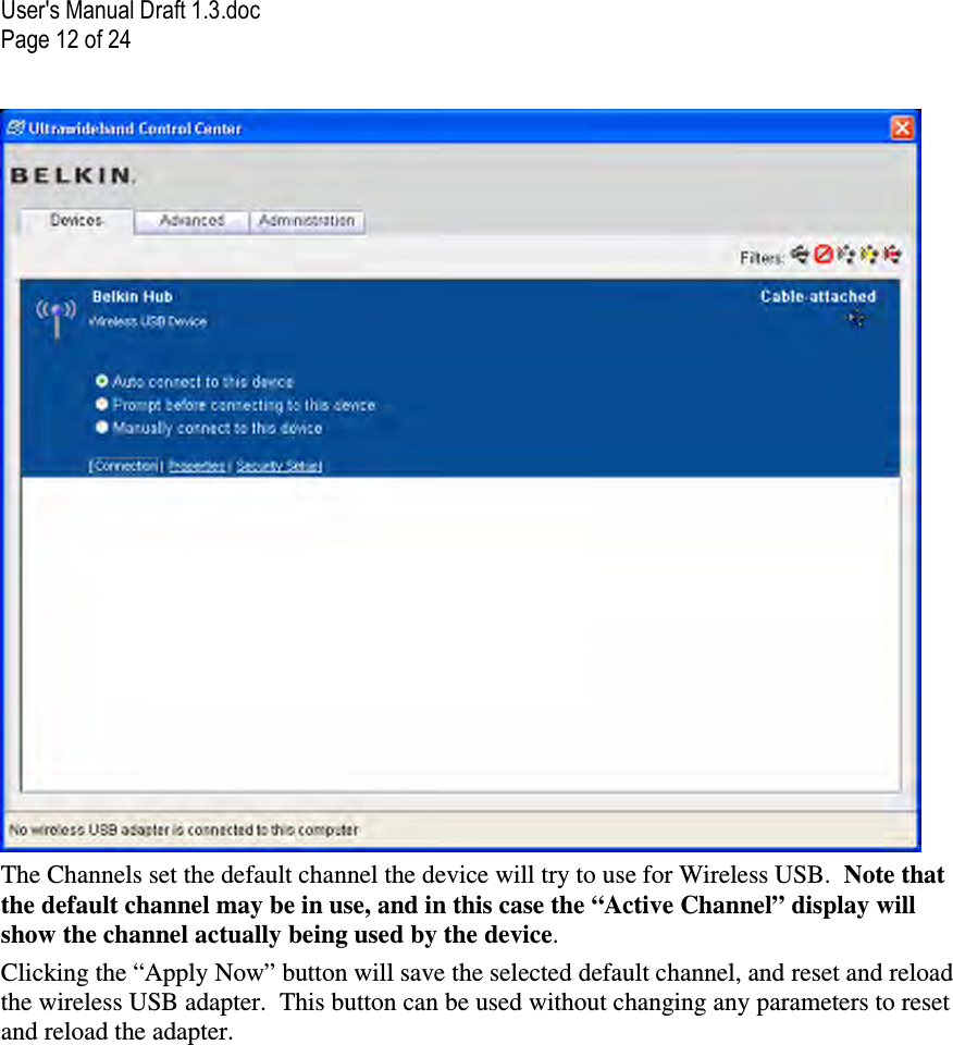
Belkin F5U302DNGL Cable Free USB 2.0 Dongle User Manual User s Manual Draft 1 3

Belkin International, Inc. Cable Free USB 2.0 Dongle User s Manual Draft 1 3

Users Manual PDF Document

User's Manual Draft 1.3.doc    Page 1 of 24 BELKIN® Wireless USB Hub and Dongle             User’s Manual  F5U302
User's Manual Draft 1.3.doc Page 2 of 24 FCC Statement – F5U302-HUB  DECLARATION OF CONFORMITY WITH FCC RULES FOR ELECTROMAGNETIC COMPATIBILITY We, Belkin International, Inc., of 501 West Walnut Street, Compton, CA 90220, declare under our sole responsibility that the product: F5U302-HUB to which this declaration relates:        CAUTION:  CHANGES OR MODIFCATIONS NOT EXPRESSLY APRROVED BY BELKIN INTERNATIONAL, INC., OF 501 WEST WALNUT STREET, COMPTON, CA 90220 COULD VOID THE USER’S AUTHORTY TO OPERATE THIS EQUIPMENT. Complies with Part 15 of the FCC Rules. Operation is subject to the following two conditions: (1) this device may not cause harmful interference, and (2) this device must accept any interference received, including interference that may cause undesired operation. This equipment may only be operated indoors.  Operation outdoors is in violation of 47 U.S.C. 301 and could subject the operator to serious legal penalties. THIS DEVICE MUST BE INSTALLED IN A LOCATION THAT IS NOT ACCESIBLE TO THE GENERAL PUBLIC.  INSTALL THE DEVICE SO THAT THE ANTENNA IS MORE THAN 20 cm FROM UNSUSPECTING PERSONNEL.  FAILURE TO INSTALL THIS DEVICE AS DESCRIBED WILL RESULT IN A FAILURE TO COMPLY WITH FCC RULES FOR RF EXPOSURE AND IS DISCOURAGED.  ONLY ANTENNAS APPROVED WITH THE DEVICE MAY BE USED. THIS DEVICE MAY NOT BE CO-LOCATED WITH OTHER TRANSMITTERS WITHOUT FURTHER APPROVAL BY THE FCC.
User's Manual Draft 1.3.doc    Page 3 of 24 FCC Statement – F5U302-DNGL  DECLARATION OF CONFORMITY WITH FCC RULES FOR ELECTROMAGNETIC COMPATIBILITY We, Belkin International, Inc., of 501 West Walnut Street, Compton, CA 90220, declare under our sole responsibility that the product: F5U302-DNGL to which this declaration relates:     Complies with Part 15 of the FCC Rules. Operation is subject to the following two conditions: (1) this device may not cause harmful interference, and (2) this device must accept any interference received, including interference that may cause undesired operation. Complies with Part 15 section 519(a) of FCC Rules. Operation of a hand held device is subject to the following conditions: (1) A UWB device operating under the provisions of this section shall transmit only when it is sending information to an associated receiver. The UWB intentional radiator shall cease transmission within 10 seconds unless it receives an acknowledgement from the associated receiver that its transmission is being received. An acknowledgment of reception must continue to be received by the UWB intentional radiator at least every 10 seconds or the UWB device must cease transmitting. (2) The use of antennas mounted on outdoor structures, e.g., antennas mounted on the outside of a building or on a  telephone pole, or any fixed outdoors infrastructure is  prohibited. Antennas may be mounted only on the hand held UWB device. (3) UWB devices operating under the provisions of this section may operate indoors or outdoors.
User's Manual Draft 1.3.doc Page 4 of 24     CAUTION:  CHANGES OR MODIFCATIONS NOT EXPRESSLY APRROVED BY BELKIN INTERNATIONAL, INC., OF 501 WEST WALNUT STREET, COMPTON, CA 90220 COULD VOID THE USER’S AUTHORTY TO OPERATE THIS EQUIPMENT. THIS DEVICE MUST BE INSTALLED IN A LOCATION THAT IS NOT ACCESIBLE TO THE GENERAL PUBLIC.  INSTALL THE DEVICE SO THAT THE ANTENNA IS MORE THAN 20 cm FROM UNSUSPECTING PERSONNEL.  FAILURE TO INSTALL THIS DEVICE AS DESCRIBED WILL RESULT IN A FAILURE TO COMPLY WITH FCC RULES FOR RF EXPOSURE AND IS DISCOURAGED.  ONLY ANTENNAS APPROVED WITH THE DEVICE MAY BE USED. THIS DEVICE MAY NOT BE CO-LOCATED WITH OTHER TRANSMITTERS WITHOUT FURTHER APPROVAL BY THE FCC.
User's Manual Draft 1.3.doc    Page 5 of 24 Table of Contents  FCC Statement – F5U302-HUB..................................................................................... 2 FCC Statement – F5U302-DNGL................................................................................... 3 Introduction ................................................................................................................... 6 Features ......................................................................................................................... 6 System Requirements ....................................................................................................................... 6 Package Includes .............................................................................................................................. 7 Technical Specifications .............................................................................................. 7 USB Port Indicator LED Status.......................................................................................................... 7 Certifications ...................................................................................................................................... 8 FCC Part 15, Subparts B and F.........................................................................................................8 Installation ..................................................................................................................... 8 Uninstalling the Software .......................................................................................................8 Operation ....................................................................................................................... 8 1.1 Devices Tab..................................................................................................................8 1.1.1 Device Connection Options .................................................................................................... 9 1.1.2 Device List Filters.................................................................................................................. 10 1.1.3 Device Security Setup Options ............................................................................................. 10 1.1.4 Device Properties.................................................................................................................. 11 1.2 Advanced Tab ............................................................................................................11 1.3 Administration Tab......................................................................................................13 System Tray.........................................................................................................................13 Pairing and Association/Connection.....................................................................................15 Automatic Association ..................................................................................................................... 15 De-Association/ (Pairing) ................................................................................................................. 15 Closing the Ultrawideband Control Center Application .........................................................15 Maintenance ................................................................................................................ 16 Troubleshooting ...................................................................................................................16 Support for USB Classes................................................................................................................. 19 Wireless Link Out of Range ............................................................................................................. 19 Extended or External Wired USB Hub Connections .......................................................................19 Reading Software and Firmware Versions ...................................................................................... 19 Technical Specifications ............................................................................................ 20 Information .................................................................................................................. 22
User's Manual Draft 1.3.doc Page 6 of 24 Introduction Belkin unleashes USB.  Congratulations and thank you for purchasing the Belkin Wireless USB Hub and Dongle. This revolutionary product lets you connect all your USB devices to your computer—wirelessly. Now you can print, play music, scan, download photos, and burn CDs from anywhere within the room, up to 30 feet away, without the hassle of connecting cables. The Hub is easy to use and gives you the freedom to roam—and stay connected. Please review this User Manual carefully so that you are sure to get the most from your Wireless USB Hub.      Figure 1: Wireless USB Dongle       Figure 2: Wireless USB Hub   Features  −  Wireless connectivity through USB for printers, cameras, scanners, and other devices to your computer, from up to 30 ft. −  Reduced cable clutter  −  Data-transfer speeds of up to 480Mbps for USB 2.0 devices −  Ports for linking up to 4 high- speed, full speed,  or low-speed devices with your computer −  Belkin Lifetime Warranty   System Requirements For PC Users −  Pentium® processor-based computer (or equivalent) with Hi-Speed USB 2.0 port available
User's Manual Draft 1.3.doc    Page 7 of 24 −  Windows® XP with Service Pack 2 −  Windows® Vista 32bit/64bit   Package Includes −  Wireless USB Hub −  Wireless USB Dongle −  Power Adapter −  USB Cable (type A to mini B) −  Installation CD −  User Manual −  Quick Start Guide  Technical Specifications Upstream Ports:  1 Downstream Ports:  4 Per-Port Voltage:  5V   Per-Port Current:  500mA Power Mode:  Self    Operating Temperature:  32° to 104° F (0° to 40° C) Storage Temperature:  -4° to 185° F (-20° to 85° C) Power Supply:   Output:   5V, 3A   Plug Size:     3.5mm   Plug Polarity:   Center-pin positive  Master Status LED  Color:   Blue Status:  Constant on when power supply is connected. Blinks when a wireless connection is established.   USB Port Indicator LED Status Individual-status LED for each downstream port  Color: Bi-color, Green or Amber Status:  Off –   No USB device plugged in (or device not enumerated).   Green –  USB device enumerated.   Amber –   Over-current Condition
User's Manual Draft 1.3.doc Page 8 of 24 Certifications  FCC Part 15, Subparts B and F  Humidity 5% to 95% non-condensing  Installation Refer to the quick start guide for installation procedures.  Uninstalling the Software If you need to uninstall the software, you can do so by using the automatic uninstaller or by using the “Windows Control Panel > Add or Remove Programs” utility.  To uninstall the software:  1.  Detach the dongle from the USB port of the PC. 1.1 Select “Uninstall” from “Start > Programs > Belkin Wireless USB”.  OR 1.2 Use the “Windows Control Panel > Add or Remove Programs” utility under “Belkin”.   Operation  The user interface for the UltraWideBand Control Center consists of a window with three tabs. These tabs are: • Devices • Advanced • Administration  1.1  Devices Tab The Devices tab shows all available or associated devices for the host system.  From the devices tab, you can set the connection mode, and view or delete association information.  Other information can be gathered about your device as well by some of the available displays in the interface
User's Manual Draft 1.3.doc    Page 9 of 24 1.1.1  Device Connection Options  The following information is displayed for each device: 1) The type of device, and optionally, a user-determined name for it. 2) Its  connection  status  (Not  available,  available,  connected,  or  cable-attached)  and,  if applicable, the strength of its wireless signal. 3) A list of options for the device (at the base of its entry). By clicking Connection for any device, the connection options will become available.  If the device is available but not currently connected, the connect button on this screen will allow the device to be connected.  Also, how the device connects in the future can be set from this menu:   Auto Connect  The device will always auto connect with no prompting from the user when it is nearby  Prompt Before Connecting  In this mode, the device will prompt the user to connect through a tray bubble when it is available
User's Manual Draft 1.3.doc Page 10 of 24  Manual Connect Mode  The device will not prompt the user when it is nearby.  The user will have to go to the connection options and push the “Connect” button.   1.1.2  Device List Filters The list of devices displayed may be filtered by clicking on the icons at the top right of the screen.  From left to right, the icons offer the following filters: cable-attached devices, known devices that are not currently present, wirelessly-connected WUSB devices, wirelessly available devices that are not connected, and wireless USB devices in the area that are not known by (that is, not security-associated with) the host PC. 1.1.3  Device Security Setup Options  The security setup option shows information about how the device was set up with the computer, and gives the user the option to delete the setup.  Deleting the security setup from the computer will not clear the setup in the device’s connection context table.  To clear the remote device security setup, connect the device by USB cable and follow the instructions for the Administration tab.
User's Manual Draft 1.3.doc    Page 11 of 24 1.1.4  Device Properties This tab lets you set a new device name for display on the local PC.  This is the name that appears in bold text at the top of the device entry.   1.2  Advanced Tab The Advanced Tab displays the currently active wireless USB channel, if any, and provides a selector to choose the default channel:
User's Manual Draft 1.3.doc Page 12 of 24  The Channels set the default channel the device will try to use for Wireless USB.  Note that the default channel may be in use, and in this case the “Active Channel” display will show the channel actually being used by the device. Clicking the “Apply Now” button will save the selected default channel, and reset and reload the wireless USB adapter.  This button can be used without changing any parameters to reset and reload the adapter.
User's Manual Draft 1.3.doc    Page 13 of 24 1.3  Administration Tab The Administration tab allows the user to edit the connection context table of a cable-attached Wireless USB device.  When a device is connected, if it is password protected, the user is prompted to enter the device supervisor password.  Upon successful entry of the supervisor password, the connection context table and password options are displayed:  To change the supervisor or user password, enter the new password in both text fields corresponding to the desired password.  Click the “Set” button the set the new password.  A confirmation message will appear indicating whether the password change was successful. To delete a password, click the “Delete” button corresponding to its text entries. To rename connection context hosts, type the new names in the text fields under “Edit associated hosts,” make sure the checkboxes corresponding to these changed names are selected, and click “Rename selected.” To delete entries from the connection context table, select the checkboxes next to the corresponding host names and then click the “Delete selected” button. System Tray  When the Ultrawideband Control Center running , the Ultrawideband icon displays in the Windows System Tray. By mousing over the icon you can tell the state of the radio either enabled or disabled.
User's Manual Draft 1.3.doc Page 14 of 24    Right clicking this icon gives you the option to exit the application, hide/show the application window, or disable/enable the radio.      Double clicking this icon will bring up the Ultrawideband Control Center application window.  Alternatively going to StartProgramsBelkin Wireless USBUltraWideBand Control Center can be used to launch the application.
User's Manual Draft 1.3.doc    Page 15 of 24  Pairing and Association/Connection Once the Hub is powered up and completes its initialization, it is ready for association.  First-time association occurs after physically connecting Hub with the PC via USB cable. This is also called “pairing” the two entities.  After the first-time connection/association, future association is handled automatically, so that no user intervention is necessary. Automatic Association After the first manual association, the same Hub is automatically associated to the same computer whenever the Hub operates within range. To associate to another Hub, you follow the instructions for “Pairing and Association” above.  Multiple Hubs may be associated with a single host PC.   De-Association/ (Pairing) To remove an association /registration from a Hub: 1.  Open “Ultrawideband Control Center” 2.  Select “security properties” for the Hub of interest 3.  Select “Remove” to remove association from host PC.   Closing the Ultrawideband Control Center Application To shut down the UltraWideBand Control Center:
User's Manual Draft 1.3.doc Page 16 of 24 1.  Right-click the tray icon and select “Exit”.     Maintenance The following sections provide maintenance information and troubleshooting advice. Troubleshooting  • I just purchased a new wireless USB hub. What do I do get it working?  • I’ve plugged my adapter into my computer’s USB port and only one device is loaded into the windows device manager.  • How do I delete a computer that has been previously set up to work with my hub?  • I have gone through the security setup steps on my hub but still can not connect to the hub.  • Which chipsets perform best with my wireless USB hub?  • I have a WUSB device installed but I still can’t seem to connect to it. What should I check before contacting Technical Support?  • What do the status light mean?  • I have 2 hubs in my house. I can only get one to run at a time.  • I keep getting the message “No Channels Available” when I try to use one of my hubs. What does that mean?  • My laptop tries to connect to every wireless USB device in our office. How do I keep it from doing that?  1.3.1.1  I just purchased a new wireless USB hub. What do I do get it working? First check to make sure your computer has wireless USB capability built into it. If not, you will need to purchase a wireless USB adapter to be able to use the wireless USB hub. Once you know your computer will support wireless USB, you must first go though a security setup process so that your computer is aware that your hub exists. The security setup process requires a one-time use of a USB cable. This cable should have been supplied with the hub. The process is very simple. Just plug one end of the cable into your hub and the other end into your computer. The setup is automatic. You will receive a notification indicating that the setup was successful. Once you receive that notice, unplug your hub from the computer and begin using the hub wirelessly. 1.3.1.2  I’ve plugged my adapter into my computer’s USB port and only one device is loaded into the windows device manager. There are issues with some specific system chipsets. We know of no issues related to the Intel chipsets. We work with the VIA chipset as long as you use the latest software USB patch. The
User's Manual Draft 1.3.doc    Page 17 of 24 issue you have described may be related to other chipsets (ULI as example). In this case, you may be able to un-install the ULI driver, re-boot your system so that the Microsoft driver will load automatically. Other chipsets may exhibit similar problems. 1.3.1.3  How do I delete a computer that has been previously set up to work with my hub? The wireless USB hub maintains a list of computers that it can connect to securely. To delete one computer from the list, you will need to plug the USB cable into the hub and computer (like you did when you did the initial setup. You can use the USB cable that was supplied with your system or you can use one that is similar. Once they are connected, after a few seconds you will see a new Administration tab appear in the Ultrawideband Control Center. Select the Administration tab and you will see each of the computers that have been setup to communicate with this hub. Follow the instructions on the screen to delete one or more computers from this list.  If you wish to reset the hub to factory resets, press the reset button on the hub for 5 seconds. Resetting to factory defaults will delete all security setup information.  1.3.1.4  I have gone through the security setup steps on my hub but still can not connect to the hub. Check that the power light is applied and the power LED is illuminated on the hub.  If you are sure there is power to the hub, open the Ultrawideband Control Center. On the devices tab, your hub should be one of the devices listed. If it is not there, check that you do not have all the filters enabled.  You may need to perform your cable setup again. Make sure that it completes the setup process before unplugging the device.  If you see your device listed, make sure that it says “Connected” and you see green bars indicating that it is connected. If the software says “Unconnected” move your hub closer to the computer to see if that fixes the problem.  If neither of those steps work, try resetting your hub. You will need to go through the cable security setup again as this process resets to factory defaults.  1.3.1.5  Which chipsets perform best with my wireless USB hub? There are issues with some specific system chipsets. We know of no issues related to the Intel chipsets. We work with the VIA chipset as long as you use the latest software USB patch. If your system has another chipset, and you are experiencing random issues, try deleting the driver and re-booting your computer. The Microsoft driver will load automatically.  1.3.1.6  I have a device installed but I still can’t seem to connect to it. What should I check before contacting Technical Support? If no devices are shown on the connections page, make sure that none of the filters have been
User's Manual Draft 1.3.doc Page 18 of 24 applied that may be hiding the devices.  Have you completed the one-time cable security setup process? If so, Please verify that the device that was setup appears in the Devices page of the Ultrawideband Control Center software. If not, try the security setup process again following the instructions carefully. You will receive an indication that the process completed successfully. Do no unplug the cable until you receive this message.  Try moving the devices very close together first to determine if a connection can be made. If so, once the connection has been made, begin moving them further apart to determine the maximum operating distance for your environment. Note that this distance could be reduced by large solid objects placed between the two devices. The best setup would be with the devices placed in "line of sight".  Check the Windows Device Manager and verify that there are no "Unknown" devices that are related to the installation of the wireless USB hub. If they are related to the installation of the wireless USB hub, please try reinstalling the drivers or restarting the "New Hardware Wizard" to see if it will install the drivers properly. If this does not clear up the issue, you may have an incompatible system. Please contact technical support.  Check the status lights on both the adapter and hub to determine if they are in a functioning state.  Open the Ultrawideband Control Center application, select the "Advanced" tab and try changing to a different channel then see if the devices will connect.  Please determine that power is being applied to both devices (You can refer to the power LEDs at this point for verification). Try resetting the power to both devices then try the connection again.  Verify that the Host USB port on your system (where you have the adapter connected) is functional using another USB device.  If you are using any additional extension cables for connection, please remove them then retest the connection.  If possible, you may want to try the adapter and hub installation on another PC to determine if there may be a hardware incompatibility with the current system.  Verify that your system has the latest drivers available from the manufacturer installed for the motherboard chipset.  Verify that your system has the latest BIOS installed from the motherboard manufacturer.  1.3.1.7  What does the status light mean? The LED will turn solid once a connection has been established between you computer and hub.  1.3.1.8  I have 2 hubs in my house. I can only get one to run at a time. You may have a situation where both setups are access the same channel. Open the Ultrawideband
User's Manual Draft 1.3.doc    Page 19 of 24 Control Center software and select the Advance tab. By default, both should operate out of the box in the same environment. Check to see if both happen to be set to run on the same channel. If this is the case, set each to a different channel. 1.3.1.9  I keep getting the message “No Channels Available” when I try to use one of my hubs. What does that mean? If you have multiple hubs in the same environment, you may have reached the limit of the number of channels that are available. Free-up a channel by stopping the wireless USB communications on one of the configured setups. 1.3.1.10  I have lost my password, how do I reset it? Resetting passwords can only be accomplished by resetting the device to it's factory defaults by pressing and holding the reset button for 5 seconds. Not included on all product versions. 1.3.1.11  My laptop tries to connect to every wireless USB device in our office. How do I keep it from doing that? Automatically connect is set as the default. In the Devices tab in Ultrawideband Control Center you can change the connection option to Prompt or Manual connect.   Support for USB Classes Audio devices (“USB Audio” class) and some webcams (“USB Video” class), which have isochronous end points, are not supported by the Hub. Wireless Link Out of Range If you are experiencing frequent wireless-link breaks, the Hub may be out of range—the solution is to shorten the range between the dongle and Hub. Extended or External Wired USB Hub Connections If you are connecting the dongle to a PC via an external wired USB hub, we recommend that you: •  Apply external power to the wired USB hub. •  Do not use the external hub during initial connect and driver installation.  Reading Software and Firmware Versions In order to ensure that you are working with the latest version of software and hardware, you can check the versions of each component as follows:  Utrawideband Control Center Application Right-click the title bar of the Ultrawideband Control Center Application and click “About”
User's Manual Draft 1.3.doc Page 20 of 24 Drivers version  Go to Windows Device manger and Right-click the Belkin wireless driver(s) and select “Properties”. Read the “Driver Version” from the “driver” tab section. Wireless Wireless USB Dongle firmware version Run the EEPROM update from startprogramsBellkin Wireless USB EEPROM Update Utility. Wireless USB Hub firmware version Run the EEPROM update from startprogramsBellkin Wireless USB EEPROM Update Utility.  Technical Specifications  Model Number  F5U302-DNGL  — Wireless USB Adapter(dongle) F5U302-HUB – Wireless USB 4-Port Hub UWB Chipset  WiQuest WQST110 BB/MAC + WQST101 RF IC  Operational Range  Up to 30ft. (~10m) PHY Data Rate  Up to 1037Mbps (automatically selected) Frequency Range  3.1GHz to 4.8GHz; supporting 3 sub-bands, 528MHz each RF Modulation Type Multiband OFDM Max. Output Power  80µW (-41.25 dBm/MHz max.) Max. Power Consumption HWA — 2.1W (420mA max. @ 5VDC from USB port) DWA — 15W (3A @ 5VDC from external power supply) USB End-Point Types Bulk in/out, Interrupt, Control Number of End Points 20 end points USB Power Drive  Powers up to 4 USB external devices (500mA @ 5VDC each) USB Association Type Host GUI-based association LED Indicators  Link  PCB Size  HWA — 21 by 63mm DWA — 61 by 94mm Antenna  HWA — external UWB omni-directional antenna DWA — external UWB omni-directional antenna
User's Manual Draft 1.3.doc    Page 21 of 24 Operating Temperature Range 0° C to 40° C  Operational Humidity Less than 95% PHY Compliance   Complies with WiMedia® PHY spec. rev. 1.0 FCC Compliance   Complies with FCC CFR 47 Part 15 subpart F; UWB intentional radiation and subpart B. USB Hub Compliance  Complies with USB 2.0/1.1 OS Compliance   Microsoft® Windows XP SP2; Microsoft® Windows Vista ; Microsoft® Windows Vista  32 bit/64 bit; Windows Plug-and-Play-compliant Coexistence  Coexists with standard WiMedia devices Coexistence  with  co-located  additional  dongles  or  UWB systems (FFI, TFI schemes) Wireless channel selection  Channel Name TFC  Channel Band Search Pattern 9  TFC1  F1  F 2  F3  F1  F2  F3 10  TFC2  F1  F3  F 2   F1   F3  F 2 11  TFC3  F1  F1  F 2   F2   F3  F 3 12  TFC4  F1  F1  F 3   F3   F2  F 2 13  TFC5  F1  F1  F1  F1  F1  F1 14  TFC6  F 2  F 2  F 2  F 2  F 2  F 2 15  TFC7  F3  F3  F3  F3  F3  F3
User's Manual Draft 1.3.doc Page 22 of 24 Information  CE Declaration of Conformity We, Belkin International, Inc., declare under our sole responsibility that the F5U302, to which this declaration relates, is in conformity with Generic Emissions Standard EN55022:1998 Class B, EN50081-1, and with Generic Immunity Standard EN50082-1:1992.  Belkin International, Inc., Limited Lifetime Product Warranty  What this warranty covers. Belkin International, Inc., warrants to the original purchaser of this Belkin product that the product shall be free of defects in design, assembly, material, or workmanship.   What the period of coverage is. Belkin International, Inc., warrants the Belkin product for the lifetime of the product.  What will we do to correct problems?  Product Warranty. Belkin will repair or replace, at its option, any defective product free of charge (except for shipping charges for the product).    What is not covered by this warranty? All above warranties are null and void if the Belkin product is not provided to Belkin International, Inc., for inspection upon Belkin’s request at the sole expense of the purchaser, or if Belkin International, Inc., determines that the Belkin product has been improperly installed, altered in any way, or tampered with. The Belkin Product Warranty does not protect against acts of God (other than lightning) such as flood, earthquake, war, vandalism, theft, normal-use wear and tear, erosion, depletion, obsolescence, abuse, damage due to low voltage disturbances (i.e. brownouts or sags), non-authorized program, or system equipment modification or alteration.  How to get service.    To get service for your Belkin product you must take the following steps:  1.  Contact Belkin International, Inc., at 501 W. Walnut St., Compton CA 90220, Attn:  Customer  Service,  or  call  (800)-223-5546,  within  15  days  of  the Occurrence.  Be prepared to provide the following information: a. The part number of the Belkin product. b. Where you purchased the product. c. When you purchased the product. d. Copy of original receipt.  2.  Your Belkin Customer Service Representative will then instruct you on how to forward your receipt and Belkin product and how to proceed with your claim.
User's Manual Draft 1.3.doc    Page 23 of 24 Belkin International, Inc., reserves the right to review the damaged Belkin product. All costs of shipping the Belkin product to Belkin International, Inc., for inspection shall be borne solely by the purchaser. If Belkin determines, in its sole discretion, that it is impractical to ship the damaged equipment to Belkin International, Inc., Belkin may designate, in its sole discretion, an equipment repair facility to inspect and estimate the cost to repair such equipment. The cost, if any, of shipping the equipment to and from such repair facility and of such estimate shall be borne solely by the purchaser. Damaged equipment must remain available for inspection until the claim is finalized. Whenever claims are settled, Belkin International, Inc., reserves the right to be subrogated under any existing insurance policies the purchaser may have.   How state law relates to the warranty. THIS WARRANTY CONTAINS THE SOLE WARRANTY OF BELKIN INTERNATIONAL, INC., THERE ARE NO OTHER WARRANTIES, EXPRESSED OR, EXCEPT AS REQUIRED BY LAW, IMPLIED, INCLUDING THE IMPLIED WARRANTY OR CONDITION OF QUALITY, MERCHANTABILITY OR FITNESS FOR A PARTICULAR PURPOSE, AND SUCH IMPLIED WARRANTIES, IF ANY, ARE LIMITED IN DURATION TO THE TERM OF THIS WARRANTY.   Some states do not allow limitations on how long an implied warranty lasts, so the above limitations may not apply to you.  IN NO EVENT SHALL BELKIN INTERNATIONAL, INC., BE LIABLE FOR INCIDENTAL, SPECIAL, DIRECT, INDIRECT, CONSEQUENTIAL OR MULTIPLE DAMAGES SUCH AS, BUT NOT LIMITED TO, LOST BUSINESS OR PROFITS ARISING OUT OF THE SALE OR USE OF ANY BELKIN PRODUCT, EVEN IF ADVISED OF THE POSSIBILITY OF SUCH DAMAGES.   This warranty gives you specific legal rights, and you may also have other rights, which may vary from state to state. Some states do not allow the exclusion or limitation of incidental, consequential, or other damages, so the above limitations may not apply to you.    BACK: BELKIN www.belkin.com  Belkin Tech Support US: 310-898-1100, ext. 2263 800-223-5546, ext. 2263 UK: 0845 607 77 87 Australia: 1800 235 546 New Zealand: 0800 235 546 Singapore: 800 616 1790
User's Manual Draft 1.3.doc Page 24 of 24 Europe: www.belkin.com/support  Belkin International, Inc. 501 West Walnut Street Los Angeles, CA 90220, USA 310-898-1100 310-898-1111 fax  Belkin Ltd. Express Business Park, Shipton Way Rushden, NN10 6GL, United Kingdom +44 (0) 1933 35 2000 +44 (0) 1933 31 2000 fax  Belkin B.V. Boeing Avenue 333 1119 PH Schiphol-Rijk, The Netherlands +31 (0) 20 654 7300 +31 (0) 20 654 7349 fax  Belkin Ltd. 4 Pioneer Avenue Tuggerah Business Park Tuggerah, NSW 2259, Australia +61 (0) 2 4350 4600 +61 (0) 2 4350 4700 fax  © 2007 Belkin International, Inc. All rights reserved. All trade names are registered trademarks of respective manufacturers listed. Windows and Microsoft are either registered trademarks or trademarks of Microsoft Corporation in the United States and/or other countries.  P75325-B ok-mk 1/3/07

Navigation menu