Beltronics USA G7M4R Radar Detector User Manual
Beltronics USA Inc Radar Detector
Manual
Advanced
PROTECTION
System
TM
with Shadow Technology®
®®®®
TM
Operating instructions for
model 975
DIGITAL PLL SYNTHESIZED
OSCILLATOR
VECTOR LR Remote
REMOTE DETECTOR
RADAR
•
LASER
•
SAFETY
Ultimate Performance. Proven Technology.

INTRODUCTION
SHADOW TECHNOLOGY®II
SELECTABLE FEATURES
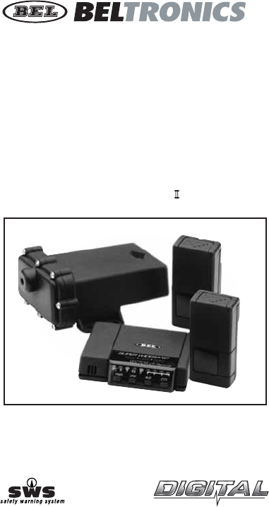
Thank you for purchasing a BELTRONICS Remote installation
Radar/Laser/Safety detector.
Your VECTOR LR Remote detector provides all the benefits of full
coverage Radar and laser detection as well as detection of the Safety
Warning System™— all in the discretion of a concealed installation.
To ensure maximum benefit from your new VECTOR LR Remote,
please read all operating instructions completely as well as the
accompanying installation instructions enclosed.
VECTOR LR REMOTE contains Shadow Technology®II, making it
undetectable to the Interceptor VG-2 or any other Radar Detector
Detector (RDD). Only Shadow Technology®II has been consistently
proven undetectable to the Interceptor VG-2.
1. Auto-Mute On/Off
Select Auto-Mute ON for several X,K, Super Wideband Ka audio alerts
followed by a “clicking” tone to quietly inform you for the duration of
the signal. Auto-Mute OFF provides a continuous series of X,K, Super
Wideband Ka audio alerts. Factory setting is Auto-Mute OFF.
(see page 9)
2. Safety Warning System®(sws™)
VECTOR LR Remote detects encoded signals from sws™ transmitters
and provides distinct alerts for: Highway Construction/Maintenance,
Highway Hazard Zones, Weather Related Hazards, Emergency/Slow
Moving Vehicles and Travel/Convenience Information.
For a complete description of sws™ of audio and visual alerts, see page 16
3. X/K/Ka Band On of Off
Select “X ON/X OFF”, “K ON/K OFF” or “Ka ON/Ka OFF” depending upon
your driving environment and selectivity requirements. Factory setting
is X/K/Ka ON. (see page 9).
4. Four Ka Narrow Frequencies
Select Ka Narrow sweeps of 33.8 GHz, 34.36 GHz, 34.7 GHz or
35.5 GHz. Narrow Band Ka frequencies are especially useful in areas
where you know a specific Ka Narrow sweep is used. Factory setting is
Super Wideband Ka ON. (see page 9)
2

3
Table of Contents
Profile of Features . . . . . . . . . . . . . . . . . . . . . . . . . . 4
Description of Features . . . . . . . . . . . . . . . . . . . . . . 5
kPower-on Test Sequence . . . . . . . . . . . . . . . . . . 5
kTutorial Mode . . . . . . . . . . . . . . . . . . . . . . . . . . . 6
kLow Voltage Warning . . . . . . . . . . . . . . . . . . . . . 6
kLoss of Antenna Connection . . . . . . . . . . . . . . . 6
kMemory Retention of Feature Selections . . . . . 6
kAdjusting the Audio Level . . . . . . . . . . . . . . . . . 6
kAudio/Visual Alert for Instant-On/Pulsed Radar . 7
kDRK (Dim/Dark) Button . . . . . . . . . . . . . . . . . . . 7
kAUD (Auto-Mute/Volume Control) Button . . . . 7
kCTY (City/Highway) Button . . . . . . . . . . . . . . . . 8
kCity X/K/Ka Mode . . . . . . . . . . . . . . . . . . . . . . . 8
kReset to Factory Settings . . . . . . . . . . . . . . . . . . 9
Selectable Features . . . . . . . . . . . . . . . . . . . . . . . . . 9
kEntering Selectable Features Mode . . . . . . . . . . 11
Understanding Radar, Laser and SWS™ . . . . . . . . . . 12
Interpretation of Alerts . . . . . . . . . . . . . . . . . . . . . . 13
kRadar Alerts . . . . . . . . . . . . . . . . . . . . . . . . . . . . 13
kTypical False Alert . . . . . . . . . . . . . . . . . . . . . . . 16
kLaser Alerts . . . . . . . . . . . . . . . . . . . . . . . . . . . . 16
kSafety Warning System®(SWS™) Alerts . . . . . . . 17
Performance Verification . . . . . . . . . . . . . . . . . . . . . 17
Troubleshooting . . . . . . . . . . . . . . . . . . . . . . . . . . . . 18
Consumer Warranty . . . . . . . . . . . . . . . . . . . . . . . . . 19
Service . . . . . . . . . . . . . . . . . . . . . . . . . . . . . . . . . . . 20
kWarranty Service . . . . . . . . . . . . . . . . . . . . . . . . 20
kPost-Warranty Service . . . . . . . . . . . . . . . . . . . . 21
Specifications . . . . . . . . . . . . . . . . . . . . . . . . . . . . . . 21
Accessories . . . . . . . . . . . . . . . . . . . . . . . . . . . . . . . . 22
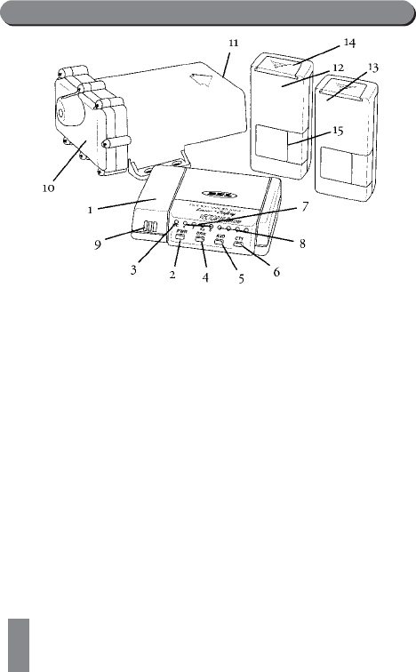
Profile of Features
1. Remote Control Panel Unit: compact design fits
discretely and easily in any vehicle.
2. PWR (Power) Button:pressing PWR briefly will turn
the unit ON. Pressing PWR a second time will cancel
the power-up test sequence.
3. H/C (Highway/City) Indicator: illuminates green
for highway mode, and amber for the City X mode.
City X/K/Ka is confirmed by the flashing green/
amber LED, followed by solid illuminator of the
amber LED.
4. DRK (Bright/Dim/Dark) Button: provides dim or
dark settings of the LED display for discreet night
travel. Audio alerts are not affected by this mode.
5. AUD (Audio-Mute) Button: provides manual muting
of X, K, Super Wideband Ka Radar and sws™ alerts.
Pressing and holding the AUD button will change the
audio level.
6. CTY (City/Highway) Button: minimizes unwanted X
band alerts without reducing sensitivity. City X/K/Ka
reduces falsing on all three bands.
4

7. X/K/Ka/sws™ Band Visual Alerts : the alert
received is confirmed by the illumination of the
appropriate LED.
8. Four-LED Display: LEDs illuminate sequentially to
confirm signal strength of Radar signals. A different
alert pattern confirms detection of Laser and Safety
Warning System®(sws™).
9. Audio Speaker: all audible alerts are emitted from
this location.
10 . Antenna Sensor: contains the electronics which
detect police Radar. This antenna sensor installs within
the engine compartment of the vehicle.
11. Antenna Face: receiving portion of the antenna sensor
must have a clear, unobstructed view of the road ahead.
12 . Front Laser Sensor: with 11’ cable mounts onto the
windshield using the supplied suction cup.
13 . Rear Laser Sensor: with 17’ cable mounts to rear
window of vehicle.
14 . Windshield Accessory Cover: remove the cover to
insert the suction cup mount.
15 . Optical Opening: Laser signals are received at this
side of the Laser sensor which must have a clear,
unobstructed view of the road ahead.
Description of Features
Power-on Test Sequence
Each time your unit is turned on, alerts for Laser, X, K,
Ka and Safety Warning System™are presented briefly.
This is immediately followed by the status of the four
Selectable Features:
1. Auto Mute – a clicking tone confirms if feature is
engaged.
2. Safety Warning System®– illumination if the green
“S” LED confirms if feature is engaged.
3. X/K/Ka Bands – illumination of the appropriate LED
confirms if band is activated. Full illumination of four
signal strength LED, coupled with the illumination of
the Ka LED confirms Super Wideband Ka mode.
5

6
4. Ka Narrow Bands –With Super Wideband Ka turned
OFF, any Ka narrow frequency which is engaged is
confirmed by rapid flashing of appropriate signal
strength LED (see page 10).
Pressing PWR anytime during the power up test
sequence will suspend the normal power up test
sequence; your unit will be ready for operation.
Tutorial Mode
The tutorial mode allows you to become more
familiar with all audible and visual alerts. To engage
this mode, press the AUD and the CTY buttons
simultaneously while the unit is ON. The audio/visual
alerts will be presented slowly in order of Laser, K, X,
Ka and SWS™. The tutorial mode will cycle these
audio/visual alerts continuously. Press the P/V button
to exit. Two “beeps” confirm exiting from the tutorial
mode. Your unit is now ON and ready for operation.
Set and Forget Memory
Any time VECTOR LR Remote is turned OFF all
feature settings you have selected are retained in the
unit’s memory. Set and Forget Memory eliminates the
need to reset your preferred feature settings each
time your unit is turned OFF and then back ON.
Low Voltage Warning
VECTOR LR Remote continually checks voltage to
ensure proper performance. The unit’s operating
range is 10.0 to 16.0 volts. If voltage falls below 10.0,
the highway (H) or city (C) indicator will flash,
coupled with a series of steady audible “beeps”.
Loss of Antenna Connection
In the event the control panel and Radar antenna are
not properly connected, the X/K/Ka band indicators
will flash, coupled with steady audible “beeps”.

7
Audio/Visual Alert for Instant-On/Pulsed Radar
This type of signal appears suddenly when a Radar
unit is “triggered”. The instant-on or pulsed alert
consists of an intense, three-second, X, K or Super
Wideband Ka audio “burst”, coupled with the flashing
of the four-LED display.
DRK (Bright/Dim/Dark) Button
The DRK button allows selection of a dim or dark setting
for all LEDS. To engage dim mode, press the DRK button
once. A single “beep” confirms your selection. To
completely cancel the illumination of all LEDS, press DRK
a second time. You’ll notice the city/highway LED remains
dim to confirm your unit is receiving power. To return to
a full bright setting, press the DRK button a third time;
two “beeps” confirm this selection. Use of the DIM
button does not affect audio alerts.
Important – if you press the DRK button and do not receive
audible confirmation, the audio level has been set too low.
AUD (Audio Mute/Volume Control) Button
Manual Muting of Audio Alerts (Radar and SWS
™
)
Whether Auto-Mute is selected ON or OFF in
Selectable Features, the audio alerts can be completely
muted by pressing the AUD button during an alert.
No audible alert will be heard for approximately 12
seconds. If the signal is still present after 12 seconds,
the unit will remain in manual mute mode.
Volume Control
Press and hold AUD button to engage the volume
control. Release the AUD button when you have reached
your desired audio setting. To reverse direction of the
volume, release and press AUD a second time.
Note – because Laser alerts are not lengthy or
sustained, muting is not required (see page 17).

88
CITY (City/Highway) Button
The City X mode has been designed to effectively
reduce unwanted audio alerts caused by intrusion
alarms, door openers, and other devices which share
X band with police Radar – without reducing
sensitivity. Signals from non-police Radar sources are
frequently encountered in urban and suburban areas,
making use of this mode ideal in these areas.
Pressing the CTY button once engages the City X
mode which is confirmed by a single “beep” and the
illumination of the yellow city LED labeled H/C. Once
engaged, weak X band signals encountered will
produce no audible alert until the signal strength
reaches a preset level. However visual alerts are
processed the instant an X band signal is detected,
keeping you quietly informed. Since most “false” X
band signals are weak, the use of the city node allows
you to drive out of their range before they reach
preset level and trigger a full audio alert. In contrast,
signals from X band traffic Radar are generally
stronger and will exceed the preset level, causing a
full X band audio alert.
Activating the City X mode will not change Super
Wideband Ka, K or instant-on X band Radar alert
patterns.
Note – the city mode has no effect on the reception
of Laser or SWS™.
City X/K/Ka
City X/K/Ka provides an alternate approach for
improving X, K and Ka band selectivity and is ideal
for use in areas with a high level of microwave
transmissions which can cause falsing on all three
bands. To engage City X/K/Ka mode, press the City
button twice. City X/K/Ka is confirmed by the
alternate flashing of the green/amber H/C LED for
one second. After the one second, the LED returns to
solid amber illumination.

9
Once engaged, weak X, K or Super Wideband Ka
signals encountered will produce no audible alerts until
the signal strength reaches a preset level. Visual alerts
are processed the instant an X, K or Super Wideband
Ka signal is detected, keeping you quietly informed.
Pressing CTY a third time returns you to highway mode;
two beeps and the illumination of the green H/C LED
confirms highway mode.
Reset to Factory Settings
You can reset your unit to factory settings for volume,
DRK, AUDIO, CITY and Selectable Features. With the unit
OFF press and hold the AUD and CTY buttons, then
press the PWR button. Two “beeps” will confirm factory
settings are reset. Your unit is now ON and ready for
operation.
Selectable Features
Auto-Mute, Safety Warning System®, X, K, Super
Wideband Ka ON/OFF and the four Ka Narrow frequencies:
33.8 GHz, 34.36 GHz, 34.7 and GHz, 35.5 GHz, are all
features that may be selected ON or OFF, depending
upon your preference.
Auto-Mute On/Off
When activated, unit will provide several X, K, Super
Wideband Ka audio alerts followed by a “clicking” tone
to keep you quietly informed for as long as the signal is
present. The clicking becomes more rapid as the
strength of the Radar signal increases. Auto-Mute
enables you to conveniently monitor extended
encounters without having to manually mute or adjust
the volume setting.
Note – because of their urgency, Laser alerts are not
affected.

10
With Auto-Mute off, unit will provide a continuous
series of X, K, Super Wideband Ka or Laser audio
alerts. This standard setting is often preferred when
background noise in a vehicle is loud. Factory setting
is Auto-Mute off. Auto-Mute ON is confirmed by the
FULL illumination of all 4 red LEDs in the signal
strength meter. Auto-Mute off is confirmed when the
same 4 red LEDs flash.
Safety Warning System®(SWS™) – LED#1
When activated, unit will detect signals from SWS™
transmitters and provide audio/visual warnings if
SWS™transmitters are in use. Factory setting is ON.
X Band On/Off – X BAND LED
When activated, unit will detect X Band signals
(10.456 GHz - 10.60 GHz).
K Band On/Off – K BAND LED
When activated, unit will detect K Band signals
(24.050 GHz - 24.205 GHz).
Super Wideband Ka On/Off – KA BAND LED
When activated, unit will detect Super Wideband Ka
signals (33.4 GHz - 36.0 GHz).
Ka Narrow Band (33.8 GHz) On/Off (LED#1)
When activated, unit will detect ONLY the 33.8 GHz
segment of the Ka bandwidth.
Ka Narrow Band (34.36 GHz) On/Off (LED#2)
When activated, unit will detect ONLY the 34.36 GHz
segment of the Ka bandwidth.

11
Ka Narrow Band (34.7 GHz) On/Off (LED#3)
When activated, unit will detect ONLY the 34.7 GHz
segment of the Ka bandwidth.
Ka Narrow Band (35.5 GHz) On/Off (LED#4)
When activated, unit will detect ONLY the 35.5 GHz
segment of the Ka bandwidth.
Note: Always operate your unit in Super Wideband
Ka unless you are certain of a specific Ka Narrow
band is used in your area of travel. When engaging
one, two, three or all four Ka Narrow bands,
remember to disengage Super Wideband Ka. If you
do not, the Super Wideband Ka will override any or
all Ka Narrow bands that you have engaged.
Entering Selectable Features Mode
1. With the unit OFF, press and hold the CTY button
followed by the PWR button. A short “beep” will
sound indicating you’re in Selectable Features mode.
2. Illumination of the appropriated LED confirms feature
is ON. Conversely, if the selected LED is flashing, the
feature is OFF.
3. Feature selection is made by pressing the CTY button
to move forward in the list of Selectable Features;
pressing DRK moves backward in the list. Selectable
Features appear in the following order and are
identified as follows:
• Auto-Mute — all signal strength LED’s illuminate.
• SWS — “S” LED
• X Band — “X” LED
• K Band — “K” LED
• Super Wideband Ka – “Ka” LED
• Ka Narrow 33.8 — first red Signal Strength LED

12
• Ka Narrow 34.3 — second red Signal Strength LED
• Ka Narrow 34.7 — third red Signal Strength LED
• Ka Narrow 35.5 — fourth red Signal Strength LED
4. Full illumination of the LED confirms feature is ON.
Flashing of the LED confirms feature is OFF. Use the
AUD button to make your selection.
5. Press the PWR button to retain your new settings for
Selectable Features. Two “beeps” will confirm that
you have exited from Selectable Features. Your unit
will be ON and ready for operation.
Understanding Radar, Laser and SWS™
Three Radar Frequencies
Three microwave frequencies have been allocated by
the FCC (Federal Communications Commission) and
are used for traffic Radar. They are:
X band: 10.45 - 10.60 GHz
K band: 24.050 - 24.250 GHz
Super Wideband Ka: 33.4 GHz to 36.0 GHz
Both X and K bands are well known to motorists who
have traveled with Radar detectors. Introduced first
was X band Radar which became common during the
1960s. In the mid 1970s, the lower powered, more
difficult to detect K band Radar was introduced. In
19 87, FCC approval was given for use of Radar
equipment using a third frequency, Ka. In response to
this, BELTRONICS introduced the first Radar
detectors capable of detecting X, K and Ka band
signals. In late 1990, FCC approval was given to
Wideband Ka: 34.2 GHz to 35.2 GHz. Once again,
BEL responded with Wideband Ka detection. Today,
your VECTOR LR Remote detects the entire Super
Wideband Ka frequency allotted for police monitoring
– 33.4 to 36.0 GHz, as well as four specific Ka
narrow frequencies.
13
Safety Warning System™(SWS™) – What is it?
The Radio Association Defending Airwave Rights, Inc.
(R.A.D.A.R) conceived and developed the Safety
Warning System™. The concept behind this system
is to warn motorists of potential road hazards by
employing Safety Warning System transmitting
devices in areas such as construction zones, accident
sites and detours. Because these SWS™transmitters
operate within the 24 GHz portion of the K band
frequency, their signals are detected by your unit.
Interpretation of Alerts
Radar Alerts
The alerts provided by your unit are affected both by
the type of transmission (continuous wave or instant-
on) and the position of the Radar source. Generally,
when you drive closer to a Radar source the intensity
of the received signals increases, resulting in a greater
number of LEDs illuminating in the four-LED display
(l or r) and a corresponding increase in the audio
alert rate. Described on the following pages are five
common types of Radar encounters and the alerts
you will typically receive.
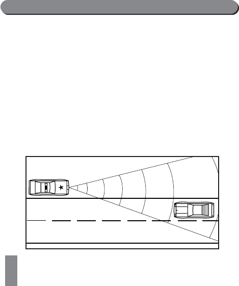
1. Stationary or moving Radar, straight ahead aimed in
your direction.
14
Since Radar signals travel in a straight line, this Radar
encounter potentially offers maximum warning range.
Once this signal is received, the initial warning
consists of the X, K, or Super Wideband Ka audio
and visual alerts and the simultaneous illumination of
one or more of the LEDs in the four-LED display. The
actual number displayed will depend upon the
strength of the signal received. As the strength of the
Radar signal increases, the audio alerts become more
rapid and more LEDs in the display will illuminate.
Assuming the Radar signal remains uninterrupted, the
audio and visual alerts will clearly indicate a “weak”
signal becoming stronger as you drive closer to the
Radar source. Remember, when the police Radar
source is moving toward you, the Radar signal
strength will increase much more rapidly than if you
are approaching a stationary source.
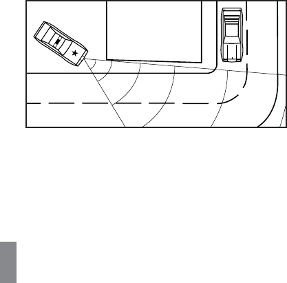
2. Stationary Radar aimed around a corner.
Under this circumstance, reaction time is
considerably reduced. Since the Radar signals are
transmitted across your line of travel, there is
generally no signal available to receive until you are
relatively close to the source. Once an alert is
received, expect the strength of the signal to increase
very quickly. Advanced warning in this situation may
be reduced.
15
3. Stationary Radar concealed by the crest of a hill
aimed in your direction.
Radar signals travel in a straight line and do not pass
through earth. Consequently, police Radar aimed at
the crest of a steep hill cannot be received until you
are at or near the top. Warning time may be minimal
(as in situation #2) since a strong signal is not
present until you are near the crest of the hill. At
this point, you may be nearly in the police officer’s
line of sight. When cresting a hill, a weak initial alert
followed by very quickly by a full alert is typical.
This alert pattern requires prompt attention.
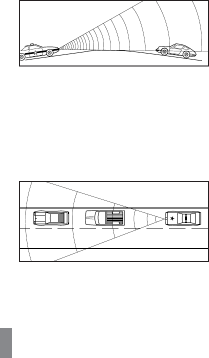
4. Moving Radar behind you, traveling in the same direction.
Police Radar signal transmitted from behind your
vehicle can be received when reflected by objects in
front of you such as large signs, bridges and trucks.
As you drive, the size and configuration of these
objects are constantly changing, causing the strength
of any reflected Radar signal received to vary.
A strong, uninterrupted alert indicates the patrol
car is close behind.

16
5. Instant-on/Pulsed Radar
If you are the target vehicle, an alert caused by
instant-on or pulsed Radar will be strong and
immediate. When encountered, your unit responds
with a three-second audio/visual warning.
Typical False Alert (Radar)
Ideally, a Radar detector should only alert in the
presence of police Radar. However, because other
devices share X and K bands with police Radar, false
alerts sometimes occur. Generally, a false signal
produces only a short audio and visual alert. Since they
are most often weak, it is possible to drive out of the
signal’s range very quickly and receive only a brief alert.
Although many times the probable source of the false
signal can be identified (supermarket, bank,
commercial building etc.), caution is advised until the
source can be confirmed. The X band alert pattern
caused by a non-police source can look like the initial
alert produced by actual police Radar. For this reason,
appropriate action is required any time an alert is
received.
Laser Alerts
When Laser is detected, the four-LED display will
illuminate in a distinct pattern. This illumination pattern
occurs rapidly and is coupled with the distinct Laser
audio alert.
If a vehicle is a long distance from the source of Laser
pulses, fewer pulses will generally be received. The closer
the vehicle is to the source of Laser pulses, the greater the
likelihood of receiving a steady stream of Laser pulses. The
reason for this is the aiming stability of the Laser gun and
the fact that it is impossible to hold the gun absolutely
still. Any movement of the gun results in motion of the
beam at the target. The further the target, the greater the
displacement if the beam and the shorter the dwell time of
the beam at the target point. Therefore, there is the
possibility of receiving only a few Laser pulses.

17
Due to these characteristics, all Laser alerts received
from your unit should be taken seriously.
Safety Warning System®(SWS™) Alerts
With the Safety Warning System™feature ON and an
SWS™transmitter in use, your detector will provide a
unique, three-second, two-tone “beep” followed by
clicking, coupled with the flashing of the (S) LED and
the appropriate LED in the four-LED display. To select
SWS™ON or OFF, see Selectable Features, page 9.
LED #1 confirms Highway Construction/Maintenance
ahead
LED # 2 confirms Highway Hazard Zone Advisory
which could indicate an accident ahead
LED # 3 confirms Weather Related Hazards such
as fog ahead
LED # 4 confirms Emergency/Slow Moving Vehicles in
transit
When only the SWS™audio warning is provided, the
category referenced is Travel/Convenience Information
or the category is unknown.
Performance Verification
Conditions that Affect Radar Alerts
If you feel your unit is not alerting properly, keep in
mind that there are many conditions that influence the
intensity or duration of an alert:
1. The police are using instant-on/pulsed Radar, in which
case no signal is transmitted until visual contact has
been made with your vehicle. For detection of this
signal, you must rely on reflected signals from Radar
directed at traffic traveling ahead of you.

18
2. The police Radar unit is positioned perpendicular to
the road, around a curve, or just over the crest of a
hill, thus, significantly reducing the reception range.
3. The highway traffic between your vehicle and the
police Radar source is heavy, blocking or reflecting
transmitted signals. The presence of several large
trucks between you and the police Radar unit could
also significantly reduce reception.
4. Rain or humid weather conditions can absorb
transmitted signals before they reach your vehicle,
again reducing detection range.
5. The police Radar unit is not properly tuned and is
transmitting outside allocated X, K or Super
Wideband Ka frequency ranges.
Conditions that Affect Laser Alerts
If you feel your unit is not properly alerting to the
presence of Laser signals, keep in mind that rain, fog,
high humidity and other weather conditions can
affect the range that the Laser beam can be detected.
Troubleshooting
Solutions for Common Problems
If your unit is not operating properly, please refer to
the outline on the next page.

19
If you experience a problem with your unit that is not
covered in the previous outline, please call, Monday
to Friday, 9 AM – 5 PM, EST, for assistance:
1-800-341-2288 USA
1-800-268-3994 CANADA
Consumer Warranty
Limited One-Year Warranty
1. This warranty covers all defects in materials and
workmanship. This warranty does not apply if the
unit has been subject to physical abuse, improper
installation, modification or if the housing or serial
number of the unit has been removed.
2. BELTRONICS manufacturers its products using parts
and components which are new or equivalent to new
in accordance with industry standard practices.
3. The enforceability of this warranty is limited to the
Problem Possible Cause Corrective Procedure
Unit not Cable not properly Check connection
receiving connected to antenna
power or control panel
Fuse in red power Replace with 1
lead is defective amp, 250 3AG fuse
“Poor” Antenna opening Reposition antenna with
detection partially blocked. unobstructed view of
range road ahead. Clean off any
accumulated debris on
antenna face.
Unit alarms Connection to antenna Re-connect cable to
every second sensor is disengaged antenna sensor
Erratic or High concentration Use city mode. Review
frequent of non-police X band section in this manual on
alerts band sources
Performance Verification
.

20
original consumer purchaser and is not transferable
to, or enforceable by, any subsequent owner.
4. In the event of a defect, malfunction or other failure
to conform to this warranty, BELTRONICS will, at its
sole discretion, repair or replace the unit at no charge.
You are responsible for all shipping costs in connection
with warranty service pursuant to this warranty.
5. This warranty commences on the date of retail purchase
and shall be effective for a period of one year.
6. There are no express warranties covering the unit
other than those set forth in this warranty. All implied
warranties are limited to the one-year period of this
warranty and no warranties, expressed or implied,
extend beyond this one-year period. Some states do
not allow limitation on how long an implied warranty
lasts, so the above limitation may not apply to you.
7. BELTRONICS will in no event be liable for any
consequential, incidental, indirect or special damages
(including, but not limited to, lost profits) arising
out of or in connection with the use, misuse or function
of the unit. Some states do not allow the exclusion of
limitation of incidental or consequential damages, so the
above limitation or exclusion may not apply to you.
8. This warranty gives you specific legal rights and you
may also have other rights which vary from state to
state.
9 . You must provide a copy of a dated sales receipt for
your unit in order to receive service under warranty.
Service
Warranty Service
If you feel your detector is not functioning properly
please review this manual, particularly the section on
Performance Verification
. If you still feel service is
required, please follow the instructions below:

21
1. To obtain service during the one-year warranty
period, please call the appropriate number below to
obtain a Return Authorization (RA) Number and the
proper mailing address. Clearly mark the RA number
on the exterior of a suitable mailing package before
sending your detector, postage paid and insured.
1-800-341-2288 USA
1-800-268-3994 CANADA
2. For your own protection, obtain a proof of delivery
receipt. Shipping costs are your responsibility.
3. Enclose with your unit the following information:
(a) Your name, complete return address and written
description of the problem (no P.O. Box please).
(b) A telephone number where you can be reached
during regular business hours.
(c) A copy of your dated sales receipt.
Post-Warranty Service
The following arrangements apply if the one-year
warranty period has expired or you are not able to
provide a copy of your dated sales receipt indicating
purchase within the past twelve months.
1. Return your unit to the appropriate address under
Warranty Service
and follow steps 1 through 3(b)
outlined in that section.
2. Enclose with your unit $85 US or $115 CAN to cover
inspection and postage return.
Specifications
Radar Receiver Frequencies: 10.525 GHz ±50 MHz
(X band), 24.150 GHz ±110 MHz (K band), 33.4 GHz
to 36.0 GHz (Super Wideband Ka), Ka Narrow:
33.8 GHz, 34.36 GHz, 34.7 GHz, 35.5 GHz.
Laser Wavelength: 905 nm

22
Operating Temperatures: -4°F to 158°F (-20°C to 70°C)
Power Supply Requirements: 13.8 Volts, 250 mA
Radar Antenna Type: patented diecast horn with
integrated transition to microstrip mixer
Weight: 7.0 ounces (Antenna Sensor), 3.0 ounces
(Control Panel), 1.8 ounce (Laser Sensor)
Maximum Dimensions
3.66” (L) x 3.14”(W) x 1.77” (H) (Antenna Sensor)
2.25” (L) x 2.0”(W) x .66” (H) (Control Panel)
2.62” (L) x 1.24”(W) x .72” (H) (Laser Sensors)
BELTRONICS reserves the right to incorporate design improvements which may
not be reflected in the specifications listed in this owner’s manual.
Accessories
If you require any additional accessories, replacement
accessories or any accessory which is not included
with your unit, call to order or for more information,
Monday to Friday, 9 AM-5 PM, EST.
1-800-341-2288 USA
1-800-268-3994 CANADA
MODEL COST COST
DESCRIPTION NUMBER USA CANADA
Radar Antenna 975 $170.00 $300.00
Control Panel
In-Dash Mounting Kit DA-55 $8.50 $12.00
Control Panel
Mounting Kit DA-56 $8.50 $12.00
VECTOR LR Remote
Control Panel DA-504 $67.00 $93.00

23
Rear Laser Sensor DA-915-R $50.00 $70.00
Front Laser Sensor DA-915-F $50.00 $70.00
Antenna Mounting Kit DA-82 $1300 $18.00
Antenna Reflector DA-83 $10.00 $14.00
Owner’s Manual 975 N/C N/C
Modifications not expressly approved by the
manufacturer could void the user’s FCC granted
authority to operate the equipment.

Head Office
2422 Dunwin Drive
Mississauga, Ontario
Canada L5L 1J9
1-800-341-2288 USA
1-800-268-3994 CAN
wwwwww..bbeellttrroonniiccss..ccoomm
This product is subject to one or more of the following patents:
U.S.P. #4,571,593 C.P. #1,187,586
#4,630,054 #1,187,602
#4,961,074 #1,295,714
#4,952,936 #1,295,715
#5,402,087
#5,446,932 Other Patents Pending
Safety Warning System®L.C.–Patents Pending
, Fundamental Mixer Technology, FMT are registered trademarks of
BELTRONICS. VECTOR LR, Total Tracking Laser and TTL are trademarks of BELTRONICS.
Safety Warning System and SWS are trademarks of Safety Warning System L.C.
Printed in Canada 273004-08
TM
Ultimate Performance. Proven Technology.