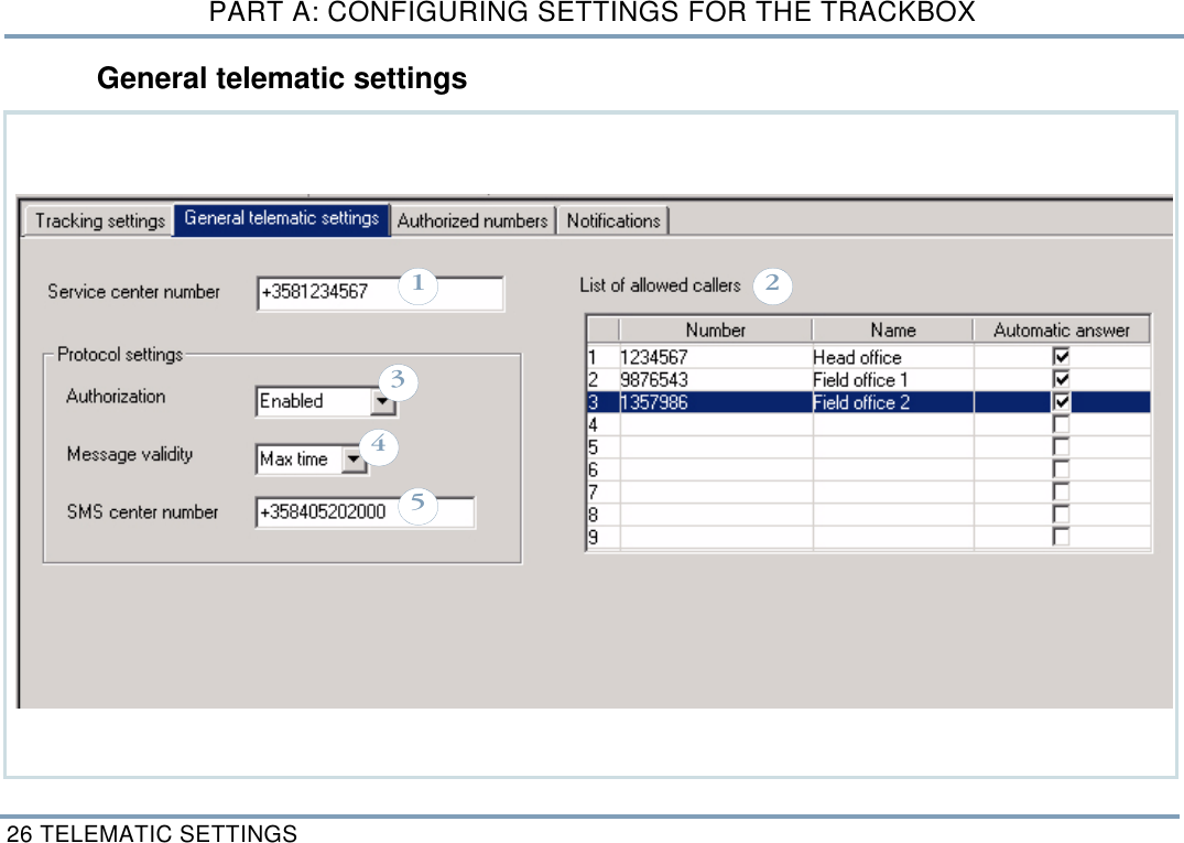
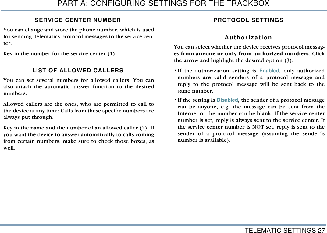
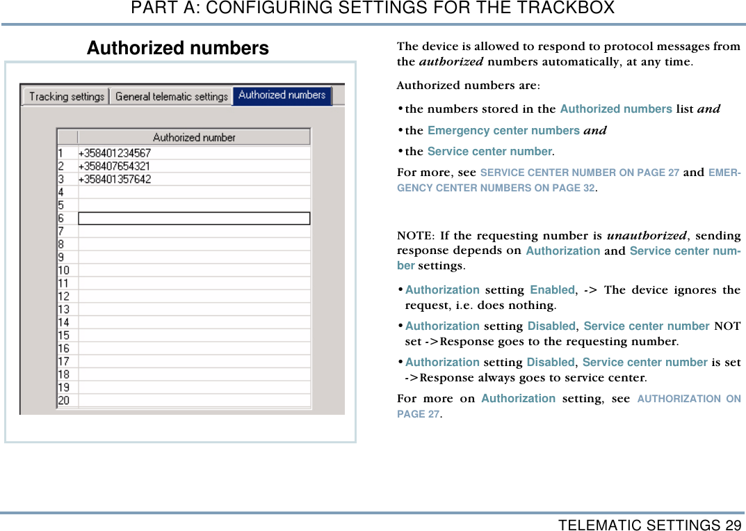
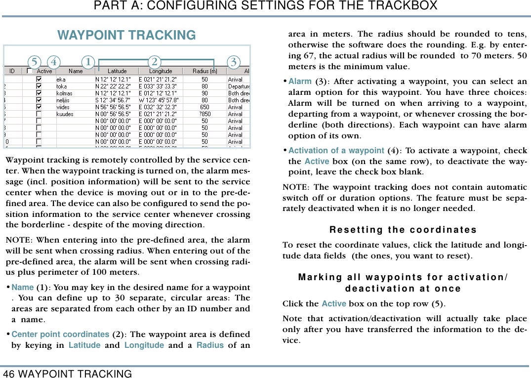
Benefonj TGP78AB Trackbox User Manual TrackBox21Draft

Benefon Oyj Trackbox TrackBox21Draft

users manual

 BENEFON TRACKBOX 2.1OperatingInstructions Publication number: YZ2655-0  All rights reserved.© Benefon Oyj, 2004.
2   FCC/INDUSTRY CANADA NOTICEThis device complies with part 15 of the FCC Rules. Operation is subject to the following two conditions: - This device may not cause harmful interference.- This device must accept any interference received, including interference that may cause undesired operation.   CERTIFICATION INFORMATION- FCC ID: QFPTGP78AB- IC: 4350ATGP78ABInformation in this manual is subject to change without notice. BENEFON reserves the right tochange or improve their products and to make changes in the content without obligation to notifyany person or organization of such changes or improvements. BENEFON is not responsible forany loss of data, income or any consequential damage whatsoever caused.   Manufacturer: Benefon Oyj, P.O. Box 84, 24101 Salo, Finland Web site: www.benefon.comNOTE: Before you start using the device, carefully read through the device documentation:Installation Guide and Operating Instructions, especially  Important safety information at the endof this manual.
 3CONTENTSPART A: CONFIGURING SETTINGS FOR THE TRACKBOX ............................................................7MPTP MESSAGES AND REMOTE CONFIGURATION (OTA)...................................7THE BENEFON CONFIGURATOR SOFTWARE FOR TRACKBOX..........................................8Connecting the Trackbox to theBenefon Configurator.................................................8THE CONFIGURATION PORT.............................................................. 9Loading settings from the Trackboxto the software............................................................10Saving settings in a computer disk...........................10Changing default mobile phone ................................11Transferring settings from thesoftware to the Trackbox ...........................................11Disconnecting the Trackbox from the software........................................................12ACTIVATING NEW FEATURES.........................................12SHORT MESSAGES ..........................................................13Reading and editing existing messages...................13Deleting a short message ..........................................13Writing and sending a short message ......................14PHONE BOOKS.................................................................15Editing and adding an entry.......................................15Deleting entries...........................................................15Arranging entries........................................................15Moving and copying entries.......................................16USER SETTINGS ...............................................................16Phone time and date...................................................16Activity timer...............................................................16SETTING THE ACTIVITY TIMER..........................................................  17Message settings ........................................................17SMS SERVICE NUMBER......................................................................  17MESSAGE TYPE...................................................................................  18MESSAGE VALIDITY TIME ..................................................................  18Port and audio settings ..............................................18AUTOMATIC ANSWER.........................................................................  18DATA PORT ACTIVITY.........................................................................  19AUDIO....................................................................................................  19VISIBLE MODE .....................................................................................  19Settings during battery loading .................................20GPS OPERATING MODE .....................................................................  20GSM ACTIVATION................................................................................  20 GPS settings...............................................................20GPS OPERATING MODE .....................................................................  20NMEA OUTPUT.....................................................................................  21ASSISTED GPS (AGPS).......................................................................  21TELEMATIC SETTINGS.....................................................22Tracking settings ........................................................22TRACKING ............................................................................................  23AREA TRACKING.................................................................................  24DEFAULT BEHAVIOUR FOR LOCATION REQUEST.........................  25REAL TIME TRACKING........................................................................  25General telematic settings .........................................26SERVICE CENTER NUMBER...............................................................  27
4 LIST OF ALLOWED CALLERS............................................................. 27PROTOCOL SETTINGS ........................................................................ 27Authorized numbers .................................................. 29Notifications ............................................................... 30POOR SATELLITE COVERAGE........................................................... 30NOTIFY SERVICE CENTER OF BATTERY STATUS .......................... 30I/O SETTINGS ................................................................... 31Emergency settings ................................................... 31EMERGENCY CONFIRMATION ........................................................... 32EMERGENCY CALL CYCLE MODE..................................................... 32EMERGENCY CALL CONNECTION WAITING TIME .......................... 32EMERGENCY CENTER NUMBERS ..................................................... 32EMERGENCY PIN ................................................................................. 33Digital output pins...................................................... 34ACTIVATING DIGITAL OUTPUT PIN ................................................... 34SETTING EVENT STATE ...................................................................... 34SELECTING EVENT.............................................................................. 34Digital input pins ....................................................... 35SETTINGS FOR DIGITAL INPUT PINS ................................................ 36STATUS MESSAGES FOR DIGITAL INPUT PINS............................... 37ALTERNATIVE FUNCTIONS FOR PIN9 ACTIVITY ............................. 37Analogue input pins................................................... 38SETTINGS FOR ANALOQUE INPUT PINS .......................................... 39STATUS MESSAGES FOR ANALOGUEINPUT PINS ........................................................................................... 40Log settings ............................................................... 43POSITION LOG INTERVAL................................................................... 43EVENT LOG SETTINGS........................................................................ 43WAYPOINT TRACKING .................................................... 46ENCRYPTING MESSAGES............................................... 47Activating encryption ................................................ 47Generating keys ......................................................... 47Selecting encryption options.................................... 48CODE SETTINGS .............................................................. 48Automatic PIN entry ................................................... 48Security code.............................................................. 48PART B: OPERATING THE TRACKBOX.............. 49INCOMING CALLS AND MESSAGES............................... 49Incoming calls ............................................................ 49Incoming short messages ......................................... 49Incoming MPTP messages ........................................ 49REMOTE CONFIGURATION MESSAGE .............................................  50AT commands............................................................. 50OUTGOING CALLS AND MESSAGES.............................. 51Resending MPTP messages...................................... 51Power notifications .................................................... 51BATTERY STATUS MESSAGES .........................................................  51CHARGER CONNECTION MESSAGES ..............................................  51Emergency cycle (I/O model only) ............................ 52EMERGENCY MESSAGES AND CALLS.............................................  52EMERGENCY CYCLE CHECK LIST ....................................................  52THE EMERGENCY CYCLE WHEN SENDINGSHORT MESSAGES AND MAKING CALLS........................................  54Making assistance call............................................... 54Sending status messages ......................................... 55 CHECK LIST FOR STATUS MESSAGES ...........................................  55Positioning features................................................... 56ACTIVITY TIMER PROCEDURE...........................................................  56RESPONDING LOCATION REQUEST(?LOC).....................................  57RESPONDING LOCATION HISTORY REQUEST (?HIS) ....................  57NETWORK POSITIONING SUPPORT..................................................  57Trace log ..................................................................... 58DOWNLOADING TRACE LOG.............................................................  58
 5PROCESSING TRACE LOG BY USING SOMEOTHER APPLICATION ......................................................................... 58Recalling event log (I/O model only) .........................59LOCAL TRANSFER .............................................................................. 59REMOTE TRANSFER ...........................................................................  60OPENING REMOTELY SENT LOG FILEIN BENEFON CONFIGURATOR........................................................... 61PROCESSING EVENT LOG IN BENEFON CONFIGURATOR............ 61PROCESSING EVENT LOG BY USING SOMEOTHER APPLICATION ......................................................................... 61PART C: POWER MANAGEMENT.........................62POWER SUPPLY...............................................................62CHARGING ........................................................................62BATTERY CARE AND MAINTENANCE ............................63DISPOSAL OF A BATTERY ..............................................63PART D: ACCESSORIES .......................................63BATTERIES, POWER SOURCES......................................................... 63EXTERNAL ANTENNAS ....................................................................... 63BWTRACKBOX CABLES, DEMO TOOL ............................................. 63PART E: IMPORTANT SAFETY INFORMATION...64DEVICE CARE AND MAINTENANCE................................64SAFETY AND PRECAUTIONS ..........................................65Telematics protocol....................................................65GPS..............................................................................65Emergency calls .........................................................65General safety notes ..................................................66FCC Statement............................................................67Radio frequency (RF) energy .....................................67Potential RF energy interference areas.....................68Ancillary equipment....................................................69BENEFON WARRANTY .....................................................70
6
MPTP MESSAGES AND REMOTE CONFIGURATION (OTA) 7PART A: CONFIGURING SETTINGS FOR THE TRACKBOXPART A: CONFIGURING SETTINGS FOR THE TRACKBOXThere are two ways to configure settings for the Trackbox: •You can use MPTP commands and transfer settingsremotely, over the air by sending a protocol message tothe device.  •You can use the Benefon Configurator software  forconfiguring settings and transfer them to the devicelocally, via the BWTrackbox data/NMEA cable. TheBwTrackbox cable must be purchased separately, it is notincluded in the Trackbox sales package.  - Benefon Configurator is compatible with Trackbox 2.1versions starting from GSM 2.Jxxxxx and IOB 040326 - Benewin Trackbox software is compatible with formerTrackbox versions. MPTP MESSAGES AND REMOTE CONFIGURATION (OTA)MPTP configuration commands are used when a remote up-date of the device configuration is needed. Update can include all telematics settings and phone num-bers, such as emergency numbers, status messages, autho-rized numbers, GPS operating mode. MPTP updates alsoinclude commands for daily usage, such as location requestand tracking commands.  The remote configuration can be used for transferring thesettings only in case the settings are coded as MPTP messag-es.For more information on MPTP messages, please see theseparate documents: Mobile Phone Telematics Protocol(MPTP), located at the Web site: www.benefon.comTRACKBOX  2.1 OPERATING INSTRUCTIONS
PART A: CONFIGURING SETTINGS FOR THE TRACKBOX8 THE BENEFON CONFIGURATOR SOFTWARE FOR TRACKBOXTHE BENEFON CONFIGURATOR SOFTWARE FOR TRACKBOX   The Benefon Configurator software is intended for configur-ing settings locally for the Trackbox. Since the Benefon Configurator is very easy to use, it is  ad-visable to make initial and other major configurations forthe device with this software. The settings done with theBenefon Configurator can be transferred to the Trackbox viathe BWTrackbox cable. Another, slightly quicker way to transfer configurationsmade by Benefon Configurator is to use the SetupLoad soft-ware. The Benefon Configurator  for Trackbox 2.1 consists of sixmain groups of settings: Short messages, Phone books, Usersettings,  Telematics settings, I/O settings and Waypoint track-ing. The settings are divided up into pages and groups in-cluding several data fields, such as Tracking settings,Emergency settings, Log settings, Message settings, Protocolsettings and so on.  When you are finished with editing the settings, you can ei-ther transfer the settings back to the device via the BWTrack-box cable immediately, or save them in a computer disk (asany normal file) for further use. Connecting the Trackbox to theBenefon Configurator    1. The BWTrackbox Data/NMEA cable may contain twosquare-end adapters. Plug the data adapter (1) into aserial port. Serial ports are located at the back panel ofyour computer. 2. Next remove the back cover of the device by screwing itoff. Plug the flat end of the BWTrackbox cable (2) inthe configuration port of the device. Make sure the  re-lease button (3) is facing up.   123
THE BENEFON CONFIGURATOR SOFTWARE FOR TRACKBOX 9PART A: CONFIGURING SETTINGS FOR THE TRACKBOX 3. Open the Benefon Configurator. 4. Choose the correct serial port from the toolbar:  Clickthe pop-up menu and highlight the desired port.   Or, choose Settings from the Edit menu. Select the De-fault communication port by clicking the check box. ClickOK to exit the menu.    5. Double-click the main node My Benefon. Or, double-click the Trackbox icon. Or, choose Connect from theMobile menu. Or, click the button Connect located onthe toolbar.  6. The software establishes a connection to the device andrenames My Benefon node according to the type and themodel of the device, in this case Trackbox.In order to transfer configura-tions made by Benefon Config-urator, the  BWTrackbox cablemust be plugged in the de-vice´s configuration port. The configuration port is lo-cated inside the device, in thelower part of the accessorymodule. Only in case the BWTrackboxcable is intended for continu-ous use, you may pierce a holeto the elastomer for the cableinlet. Otherwise, leave it intactfor improving dust and waterprotection.   THE CONFIGURATION PORT THE MAIN IDEA IS THAT THE PORT SELECTED IN SOFTWAREMATCHES WITH THE PORT, THE DATA ADAPTER IS PLUGGED IN.
PART A: CONFIGURING SETTINGS FOR THE TRACKBOX10 THE BENEFON CONFIGURATOR SOFTWARE FOR TRACKBOX7. At the same time, the software reads data from the deviceand loads it in the display. The data contains currentlyexisting settings and menus from the device. These set-tings and menus are shown as sub-nodes, such as Usersettings, and  Telematics settings. The nodes are struc-tured as the Benetree on the left side of the display. 8. If the software requests security code while loading thesettings, you must key in the code and press Ok. Formore information on security code, see SECURITY CODEON PAGE 48.  9. Click the name label Trackbox. The sub-nodes will bedisplayed as icons on the working area, i.e. the Docu-ment window, on the right.   10.You can select the desired sub-node/icon by clicking it.The data fields will be displayed. Loading settings from the Trackboxto the softwareAs you connect the device to the software, all current set-tings in the Trackbox are copied to the software. To load only part of the settings to the software, choose Con-figurator from the Edit menu (before pressing Connect but-ton). Check the desired setting groups - the groups areshown in the Mobile phone start up tasks. Click Ok while thedialog box is displayed. Unloaded settings can be loaded afterwards in the same ses-sion by choosing Open NNsettings from the Mobile menu.  Saving settings in a computer disk 1. If the device is not currently connected to the software,you can still make "off-line" configurations, save themand transfer them to the device afterwards.  When work-ing this way, data fields are available for editing via Mycomputer node.    2. To save data in a computer disk, choose Save as... fromthe File menu. 3. Select the destination drive and folder, and rename thefile the way you like. Click Save. The software stores alldata fields that the chosen node, e.g. User settings, con-tains.   TIP IT IS ADVISABLE TO ALWAYS SAVE THE SETTINGS IN THE COMPUTER DISK.THIS WAY, THE READY-MADE SETTINGS CAN BE EASILY RECALLED ANDCHECKED AT ANY TIME NEEDED, EVEN WHEN THE DEVICE IS FAR AWAY. WHEN THE SETTINGS ARE STORED IN THE COMPUTER AS A NORMALFILE,  COPYING THEM TO OTHER SIMILAR DEVICES,  OR MAKINGCHANGES TO THEM SHOULD BE QUITE EASY.
THE BENEFON CONFIGURATOR SOFTWARE FOR TRACKBOX 11PART A: CONFIGURING SETTINGS FOR THE TRACKBOXChanging default mobile phoneWhen any Benefon phone (or device) is connected to theBenefon Configurator, the software identifies it automatical-ly, and offers you the correct data fields for editing.  To make off-line configuration for some other Benefonphone (e.g. Esc!) when the phone is currently unavailable,you need to change the default mobile phone in BenefonConfigurator. 1. Change the default Benefon mobile phone by selectingConfigurator... from the Edit menu, or highlighting thedesired phone model from the pop-up menu, located onthe toolbar.2. Now the data fields of this "new" phone model are avail-able and can be opened from the My Computer node onthe left. 3. Click the desired node, e.g. User settings, press themouse´s right button and select New >Ok.  4. Similarily, you can close the file which is not needed anymore by clicking it, pressing the mouse´s right buttonand selecting Close. Transferring settings from thesoftware to the TrackboxWhile the Benefon Configurator is connected to the Track-box, you can save data in the Trackbox. 1. First open the Benefon Configurator document whichcontent you want to save in the Trackbox. Settings which are previously stored in a computer diskcan be recalled by choosing Open from the File menu, orpressing the corresponding function icon on the tool-bar.    2. Choose Save To Mobile from the File menu. Or, click the function icon on the toolbar.  When transferring data to the device, the previous data is re-placed with the new data.
PART A: CONFIGURING SETTINGS FOR THE TRACKBOX12 ACTIVATING NEW FEATURESDisconnecting the Trackbox from the software   1. Choose Disconnect from the Mobile menu. Or, click the button Disconnect on the toolbar. 2. Press and hold down the release button while removingthe BWTrackbox cable from the device. (The release but-ton is located on the top of the flat end of the BWTrack-box cable.)   3. In case the inlet for the BWTrackbox cable is pierced,but the cable is taken off, the hole must be covered withsome waterproof material, such as a piece of firm tape orsilicon. This needs to be done for improving water pro-tection.  4. Screw the back cover back in. ACTIVATING NEW FEATURESSome of the new features are sold separately, they are notincluded in the basic 2.1 software package. Such feature is,e.g. Encryption. When you purchase some new features, a Service activationkey is provided to you by the dealer or the manufacturer.The key is needed for activating the features. Activation can be easily done with the Benefon Configura-tor. Activation can also be done via MPTP messaging. Formore information on MPTP commands, see the separate Mo-bile Phone Telematics Protocol (MPTP) document. 1. First make sure, the phone has a cable connection to theBenefon Configurator. 2. Click Connect.   3. Select Save activation key from the Mobile menu. 4. Key in the Service activation key.     5. Click Save. 6. Click Disconnect.
SHORT MESSAGES 13PART A: CONFIGURING SETTINGS FOR THE TRACKBOXSHORT MESSAGESIn order to read, write, send and receive normal short mes-sages via the Trackbox, the Trackbox must be connected toan external device. The device attached to the Trackbox can be e.g. a computer,a laptop or a palm computer. Since the Trackbox lacks thekeyboard and screen, the external device must be providedwith these. The physical connection is established with theBWTrackbox cable. A suitable software, for example the Benefon Configurator,is needed for the communication as well.Reading and editing existing messages1. Open the Benefon Configurator.  2. Double-click the icon SMS messages. Messages are listed and can be read. Editing: Double-click the message you want to edit. Edit textand other details in the SMS edit buffer. Click Ok  whenready. Deleting a short messageTo delete a short message, highlight the message andchoose Sms, Delete message from the Edit menu. Or, select Delete by pressing the mouse´s right button.
PART A: CONFIGURING SETTINGS FOR THE TRACKBOX14 SHORT MESSAGES  1. Choose Sms, New message fromthe  Edit menu. The SMS editbuffer will be displayed. 2. Key in the message text (1) andthe recipient´s number(2). Byclicking the square next to thenumber (3), the recipient´snumber can be fetched from thePhone book, assuming the num-ber is found on SIM.   3. Make sure, the Sms service num-ber  is correct. The number canbe changed by clicking thesquare next to it (4). By select-ing the option SIM card default,the SMS service number will bepicked up from the SIM card.  Ifthe SIM card does not containthe SMS number, select the op-tion Own and key in the SMS ser-vice number. 4. Select the desired Saving/Send-ing option by checking one ofthe Action boxes (5). Completethe message by pressing Ok.32145Writing and sending a short message
PHONE BOOKS 15PART A: CONFIGURING SETTINGS FOR THE TRACKBOXPHONE BOOKSAs you open the Phone books, the memory entries stored onthe SIM card are listed and can be processed. Index numberstands for memory slot number.  Editing and adding an entry1. To edit details of an entry, click the desired entry . Toadd a new phone book entry, click a blank line (1).2. Key in the name and number(2). 3. By pressing Tab on the keyboard you can move from adata field to another.Deleting entries  1. To delete a phone book entry, click the desired entry. 2. Press Delete on the keyboard. You can also choose thecommand Delete from the Edit  menu, or by clicking themouse´s right button.  Arranging entriesArrange the phone book by Index, Name, or Number (3) ei-ther by - clicking the title - choosing  the option from the Edit menu  - clicking the mouse´s right button.•View by: This option rearranges the phone book tempo-rarily. When transferring the phone book data back to thephone, the data will be arranged by the old order.•Sort by: This option rearranges the phone book perma-nently. When transferring the phone book data back tothe phone, the data will be arranged by the new order. 231
PART A: CONFIGURING SETTINGS FOR THE TRACKBOX16 USER SETTINGSMoving and copying entries   1. To move or copy a phone book entry to another slot,click the desired entry. 2. Press Ctrl+C (for copy) or Ctrl+X (for cut) on the key-board. Click the destination line and press Ctrl+V (forpaste) on the keyboard. You can also choose the commands Copy, Cut and Pastefrom the Edit menu, or by clicking the mouse´s right but-ton. Or, you can click the corresponding function icons onthe toolbar.    3. If the destination line is reserved, you also need to con-firm, whether to overwrite the old information or not.  - To overwrite the old information, click Yes in the dia-log box.  - To preserve the old information and transfer the newinformation to another, free slot (Index number), clickNo in the dialog box. USER SETTINGSPhone time and dateTime and date can be set in the Benefon Configurator. Keyin the time and date in the GMT format (“Greenwich Time”).Date and time can be selected by clicking the arrows, aswell.  Time stamps associating MPTP messages are displayed in theGMT format, as well. Activity timer  Device can be configured to update its position e.g. once aday and report it to the service center.  Activity timer can also be used to wake up the device peri-odically to check if there are any incoming messages. If thereare no messages, the timer will return to sleep for the nextwake-up. Power up/down cycle is reasonable for saving power, espe-cially in case the device is a plain battery model. Copy Cut Paste
USER SETTINGS 17PART A: CONFIGURING SETTINGS FOR THE TRACKBOXSETTING THE ACTIVITY TIMER  Message settings SMS SERVICE NUMBERYou can store the SMS service number (1), which is neededfor sending normal short messages and telematics protocolmessages. The number must be set correctly, otherwise sending shortmessages is not possible.The SMS service number can be found e.g. in the manual ofyour local network operator. However, if you are supplied with a separate SMS servicenumber for telematics protocol messages, you may store thenumber in the Protocol settings data field. For more infor-mation, see GENERAL TELEMATIC SETTINGS ON PAGE 26.Configuring separate SMS service number for protocol mes-sages is recommended in case the Activity timer is used (seeabove). 1231. Start time: Key in the date and time, when thetimer is switched on for the first time. Starttime can be selected by clicking the arrows(1), as well.  2. Interval: Key in the interval for wake-up (2). Ifthe interval is set to zero, the timer is NOT inuse.  3. Positioning skip: It may not be necessary to de-termine current position each time when thetimer is turned on. By setting a value N for theposition skip (3), the device can be pro-grammed to only determine the position everyNth time the timer is turned on.321
PART A: CONFIGURING SETTINGS FOR THE TRACKBOX18 USER SETTINGSMESSAGE TYPE You can determine what kind of a message you are process-ing. You can choose the message type from these: Text, Fax,X400, Email, Ermes, or Data. When using the device for normal or MPTP messaging, clickthe arrow and highlight Text for message type (2). MESSAGE VALIDITY TIMEYou can select the length of validity for normal SMS messag-es, i.e. for how long the SMS messages are stored in the serv-er of the operator. You can choose the message validity from these: 1 hour, 6hours, 24 hours, 1 week or Maximum time. Click the arrow and highlight the desired option (3). NOTE: The length of validity for telematics protocol messag-es is selected in General telematic settings. For more informa-tion, see GENERAL TELEMATIC SETTINGS ON PAGE 26. Port and audio settings AUTOMATIC ANSWER The automatic answer function can be turned on or off (1). •If the Automatic answer is turned on (the box is checked),a voice call to the device from any number is possible. •If the Automatic answer is turned off (the check box is leftblank), making a voice call to the device can only be donefrom a number listed as an allowed caller. Allowedcallers are stored in the General telematics settings. Formore information, see GENERAL TELEMATIC SETTINGS ONPAGE 26.  1234
USER SETTINGS 19PART A: CONFIGURING SETTINGS FOR THE TRACKBOXThe device contains a built-in microphone. By making a callto the Trackbox, the caller (e.g. service center) can listen inthe Trackbox and its surroundings. After certain number ofrings, the device answers an incoming call automatically byopening audio connection. DATA PORT ACTIVITYData port setting must be turned on in case the Trackbox isneeded for data transfer or connected to some external de-vice.  Turning the data port off decreases power consumption(2). •To turn the data port on, check the box. •To turn the data port off, leave the check box blank.   AUDIO •Internal: The device contains an internal microphone anduses it. •External: Audio comes from some external device via theconfiguration port. Click the arrow and highlight the currently used option (3).  VISIBLE MODEThe device can be set to operate •In visible mode (the box is checked) or •In invisible mode (the box is left blank). In Visible mode the LEDs are lit as described in the Track-box Installation Guide. Invisible mode is for making the device more difficult to de-tect (4). In invisible mode only some of basic LED patternsare lit, e.g. powering up/down. This way e.g. sending emer-gency messages can be done very discreetly.
PART A: CONFIGURING SETTINGS FOR THE TRACKBOX20 USER SETTINGSSettings during battery loading GPS OPERATING MODEYou can select, which one of the GPS power modes is onwhile the device is being charged (1). Set the GPS off, in case  •the time reserved for charging is quite short or•GPS functions are not needed during charging process.  By selecting No change, the GPS mode remains in the previ-ously configured mode.  GSM ACTIVATION You can select, whether the GSM is turned on or off whilethe device is being charged (2).In case the GSM functions are needed even during thecharging, this setting must be turned on: By checking thebox, the GSM is activated during charging.    GPS settingsGPS OPERATING MODEThe GPS receiver in the Trackbox uses power saving optionsfor ensuring maximum battery capacity. The GPS receiver has three modes (1): •Off •Low Power with the power saving option  - the time needed for position fix depends on condi-tions. If the GPS does not manage to calculate the posi-tion, it will fall asleep for a while and retry to calculatethe position later on.  •Full power without the power saving option. 211234
USER SETTINGS 21PART A: CONFIGURING SETTINGS FOR THE TRACKBOXOperating mode depends on the way, the device is used. Autonomous system, i.e. a plain battery model, normallyuses either Low Power or Off mode, while a device with con-stant power supply uses Full Power mode (i.e. the standardand I/O models).NMEA OUTPUTThe NMEA port output can be turned on or off (2).  This de-vice supports a subset of NMEA 0183 v2.0 output protocol,which is used for transferring position data between the de-vice and a navigation system, such as a Search and Rescueapplication. For the connection you also need a BWTrack-box Data/NMEA cable (an accessory).  - By  selecting  Off, you will turn the NMEA output portoff.  - By selecting a transferring speed you will turn theNMEA output port on.    When the NMEA output is turned on, the device will con-sume slightly more power. ASSISTED GPS (AGPS)Trackbox has capability to receive assistance to the GPS re-ceiver in order to speed up the initial position calculation.This is very useful feature if the device is in poor satellitecoverage. Assistance can be supplied over the Mobile Phone Telemat-ics Protocol in a binary coded protocol message. The mes-sage will contain ephemeric and almanac data which isbased on a rough position calculated by e.g. GSM networkparameters (Cell-ID, CI-TA etc). The assisted GPS is sup-plied from a third party station server.  Using the AGPS does NOT affect the accuracy of the posi-tion. If  the last position fix is deemed to be too old, and theAGPS is set, the AGPS feature is automatically used to speedup the position determination.  The cost of  the AGPS service is determined on the contractof the service provider. You can specify settings for ordering assisted GPS informa-tion from a service provider. •Number of satellites: Select the number of satellites (3). However, please note that the more satellites selected,the faster the service but the higher the charge.  •SMS number: Key in the SMS number of the AGPS service(4).
PART A: CONFIGURING SETTINGS FOR THE TRACKBOX22 TELEMATIC SETTINGSTELEMATIC SETTINGSTracking settings1ab23 4baabcdcba
TELEMATIC SETTINGS 23PART A: CONFIGURING SETTINGS FOR THE TRACKBOXTRACKING  Tracking is remotely controlled by the service center. Whenthe tracking function is turned on, the position informationis sent to the service center several times in sequence. If the device is temporarily switched off, battery is removed,or the power supply is some other way disconnected, thetracking record (e.g. amount of messages) will be reset andstart from the beginning. Essential phone numbers, such as Service center number andSMS service number, must be configured in the device. In theBenefon Configurator, these numbers can be set in the Gen-eral telematic settings. For more information, see GENERALTELEMATIC SETTINGS ON PAGE 26.    DurationYou can select, for how long or on what terms tracking willbe on (1a). After that, the tracking will be turned off auto-matically. Only one of these options can be turned on at once.•Continuous: The tracking will be turned on until furthernotice. !Deactivation message must be sent separately. •Amount of sent messages: Tracking will be on untildefined amount of messages has been sent to the servicecenter. Key in the amount.   •Duration: Tracking will be on for a period of time. Key inhow many days, hours and minutes the tracking should beon.     •End time: Tracking will be on until the end time isreached. Key in the date and time, the tracking should beturned off. Date and time can be selected by clicking thearrows, as well. IntervalThe given interval, e.g. 60 minutes, indicates that the devicewill send its position to the service center at intervals of 60minutes. Key in the tracking interval in minutes (1b). ActivationMake sure all the required settings for tracking are complet-ed before activating the function. Such settings are, e.g. du-ration and interval. New settings can be applied only while the tracking is deac-tivated. You can activate tracking by sending a specific MPTP mes-sage to the device.
PART A: CONFIGURING SETTINGS FOR THE TRACKBOX24 TELEMATIC SETTINGSAREA TRACKING Area tracking is remotely controlled by the service center (orsome other authorized number). When the area tracking isturned on, the position information will be sent to the ser-vice center only when the device is moving in or out of thepre-defined area.  The area can be determined by keying in a center point anda radius of an area. The area tracking does not contain theduration option, i.e. the area tracking will never be turnedoff automatically.Essential phone numbers, such as Service center number andSMS service number must be configured in the device. In theBenefon Configurator, these numbers can be set in the Gen-eral telematic settings.  For more information, see GENERALTELEMATIC SETTINGS ON PAGE 26.  IntervalThe given interval, e.g. 60 minutes, indicates that the devicewill send its position to the service center at intervals of 60minutes, but only in case the device is located outside of thedetermined area. Key in the interval for area tracking in minutes (2a).   Center pointKey in the center point name (e.g. Home) and enter coordi-nates (2b).   RadiusKey in the desired radius in 10 meters (2c). E.g. by entering5, your actual radius will be set for 50 meters (minimum). Alarm modeYou can set an alarm to alert when crossing the borderlineof an area (2d). The alarm can be set to alert either when arriving in or de-parting from the particular area. ActivationMake sure all the required settings for area tracking are com-pleted before activating the function. Such settings are, e.g.interval, center point, radius and alarm mode (at arrival ordeparture). New settings can be applied only while the area tracking isdeactivated. You can activate area tracking by sending a specific MPTPmessage to the device.
TELEMATIC SETTINGS 25PART A: CONFIGURING SETTINGS FOR THE TRACKBOXDEFAULT BEHAVIOUR FOR LOCATION REQUEST The device may receive several different messages request-ing location. Such messages can be, e.g. Location request(?LOC) messages, or Location history request (?HIS) messag-es. (For more information on how to create location requestmessages, see the separate MPTP document.) You can define, which way the device responds the locationrequests. The message always includes a time stamp indicat-ing age of the position. Choose from the options below by checking the corre-sponding box in the Benefon Configurator. •Send last known position (4a): When the device receivesthe location request, the device immediately recalls thelatest position found in the memory and sends it to therequesting number. The position can be quite old. If thedevice does not have a position at all, the message will besent without position. •Attempt to acquire a fresh position for a while (4b): Whenthe device receives the location request, the device imme-diately switches the GPS on (if it is currently off), updatesposition, sends it and switches the GPS off. Then thedevice returns to normal idle mode. Only in case the posi-tion update is NOT possible within 3 - 4 minutes, thedevice will send the latest position found in the memoryto the requesting number.•Send last known position at once (4c): When the devicereceives the location request, the device immediatelyrecalls the latest position found in the memory and sendsit to the requesting number. In addition to that, thedevice tries to update the position for 3 - 4 minutes. If theposition update succeeds, the new position is sent to therequesting number, as well. REAL TIME TRACKING Real time tracking can be initiated by sending a detailedMPTP message to the device. Real time tracking is done via CSD data call. After successfulconnection, the device starts to forward NMEA data directlyfrom the GPS over CSD call.  If sending a CSD call fails, the device will send an SMS mes-sage informing what went wrong. •Key in the CSD number (3a). The number must be config-ured in the device before the function can be used.   •Key in the SMS number (3b). The number must be config-ured in the device, as well.
PART A: CONFIGURING SETTINGS FOR THE TRACKBOX26 TELEMATIC SETTINGSGeneral telematic settings13452
TELEMATIC SETTINGS 27PART A: CONFIGURING SETTINGS FOR THE TRACKBOXSERVICE CENTER NUMBERYou can change and store the phone number, which is usedfor sending  telematics protocol messages to the service cen-ter. Key in the number for the service center (1). LIST OF ALLOWED CALLERS You can set several numbers for allowed callers. You canalso attach the automatic answer function to the desirednumbers. Allowed callers are the ones, who are permitted to call tothe device at any time: Calls from these specific numbers arealways put through.   Key in the name and the number of an allowed caller (2). Ifyou want the device to answer automatically to calls comingfrom certain numbers, make sure to check those boxes, aswell. PROTOCOL SETTINGSAuthorizationYou can select whether the device receives protocol messag-es from anyone or only from authorized numbers. Clickthe arrow and highlight the desired option (3). •If the authorization setting is Enabled, only authorizednumbers are valid senders of a protocol message andreply to the protocol message will be sent back to thesame number. •If the setting is Disabled, the sender of a protocol messagecan be anyone, e.g. the message can be sent from theInternet or the number can be blank. If the service centernumber is set, reply is always sent to the service center. Ifthe service center number is NOT set, reply is sent to thesender of a protocol message (assuming the sender´snumber is available).
PART A: CONFIGURING SETTINGS FOR THE TRACKBOX28 TELEMATIC SETTINGSMessage validityYou can select the length of validity for telematics protocolmessages, i.e. for how long the SMS messages are stored inthe server of the operator (4). This setting can be used to avoid massive helping efforts incase an emergency message has been sent a week ago andthere is reason to believe that help is no longer needed.You can choose the message validity from these: 1 hour, 6hours, 24 hours, 1 week or Maximum time.The length of validity for normal SMS messages is selectedelsewhere, in the User settings. For more information, seeMESSAGE VALIDITY TIME ON PAGE 18.  SMS center numberYou can set separate SMS center number for the telematicsprotocol messages. If the number is not set, the normalshort message service number is used instead.Key in the SMS center number (5).
TELEMATIC SETTINGS 29PART A: CONFIGURING SETTINGS FOR THE TRACKBOXAuthorized numbers The device is allowed to respond to protocol messages fromthe authorized numbers automatically, at any time. Authorized numbers are: •the numbers stored in the Authorized numbers list and •the Emergency center numbers and •the Service center number. For more, see SERVICE CENTER NUMBER ON PAGE 27 and EMER-GENCY CENTER NUMBERS ON PAGE 32. NOTE: If the requesting number is unauthorized, sendingresponse depends on Authorization and Service center num-ber settings. •Authorization setting Enabled, -> The device ignores therequest, i.e. does nothing. •Authorization setting Disabled, Service center number NOTset ->Response goes to the requesting number. •Authorization setting Disabled, Service center number is set->Response always goes to service center. For more on Authorization setting, see AUTHORIZATION ONPAGE 27.
PART A: CONFIGURING SETTINGS FOR THE TRACKBOX30 TELEMATIC SETTINGSNotifications POOR SATELLITE COVERAGE Notify service center when satellite coverage drops: The de-vice can be configured to notify the service center if the sat-ellites are suddenly dropped and position is lost, e.g. whenentering in a building. Key in the number in minutes (1). The timeout indicates, for how long the device is allowed tostay in poor satellite coverage before sending a protocolmessage to the service center - the smaller the number youset in here, the faster the device will react to lost satellitesand the sooner the notification will be sent. NOTIFY SERVICE CENTER OF BATTERY STATUS By checking the box (2), the service center will be notifiedof some events occurred in battery status. Notifying means sending a protocol message to the servicecenter, for example in these cases: Low battery, temperaturetoo warm/too cold for charging or using battery, battery fail-ure.  12
I/O SETTINGS 31PART A: CONFIGURING SETTINGS FOR THE TRACKBOXI/O SETTINGSEmergency settings25314aba cb
PART A: CONFIGURING SETTINGS FOR THE TRACKBOX32 I/O SETTINGSEMERGENCY CONFIRMATIONYou can request the emergency center to send a confirma-tion of the emergency message. The emergency center willthen send the confirmation to the device as soon as it re-ceives the emergency message. Check the box to enable con-firmation, or leave the check box blank to disableconfirmation (1a).  You can also specify a waiting time, i.e. for how long a timethe device waits for the confirmation before trying to reachsome other emergency center number. Click the arrow andhighlight the desired option (1b).   EMERGENCY CALL CYCLE MODEYou can define the order for making emergency voice callsand sending emergency messages while the emergency callcycle is on (2). You have two choices: •Alternately: The device will make a voice call and send anSMS in pairs according to the list order, starting from thetop.  •First SMS, then calls: As the emergency call cycle is initi-ated, first the device will send the emergency messages,after which the voice calls will be made starting from thetop of the list.  EMERGENCY CALL CONNECTION WAITING TIMEYou can define for how long a time the device tries to call asingle emergency center number before moving on to thenext number in the list of emergency center numbers. Click the arrow and highlight the desired option (3).   EMERGENCY CENTER NUMBERS The emergency (SOS) messages are sent and emergencycalls are made to the numbers stored in the emergency cen-ter list (4). The emergency call (i.e. emergency cycle) can contain both(voice) calls and messages. Calls can be made to mobilephone numbers, or normal phone numbers. Messages areprotocol messages sent to mobile phones via SMS. Theemergency message contains both GPS coordinates andGSM network measurement report. The numbers are in priority order, starting from the top ofthe list. These numbers work as "a chain": If the first number is unreachable (after two attempts), thedevice calls or sends the short message to the second num-ber. If it is not answered either, the device will go on to thethird number on the list and so on.
I/O SETTINGS 33PART A: CONFIGURING SETTINGS FOR THE TRACKBOXThe device tries to reach contact with the other numbersonce before moving on to the next number in the list. Ifthere is still no answer after going through the whole list,the calling procedure will be started all over. The devicemakes three rounds.Key in the numbers. To enable a number, check the boxwhich associates the number.  EMERGENCY PIN Activating emergency pin•To activate the emergency input pin, check the Enabledbox (5a). •The input pin is NOT in use when the check box is leftblank. A signal of this pin is not detected at all.    Setting event state   Determine status for the emergency pin. The circuit can beset for High or Low. Click the arrow and highlight the de-sired option (5b). A change in the status causes grounding of a pin. An eventcausing this can be, e.g. pressing the emergency switch. After the change in status is registered, the device will startan emergency cycle and store the information in the Eventlog.  - For more information on Emergency cycle, see EMER-GENCY CYCLE (I/O MODEL ONLY) ON PAGE 52.  - For more information on Event log, see EVENT LOG SET-TINGS ON PAGE 43. Defining notification delay The device can be configured to allow some millseconds topass until the event will be registered or interpreted as acause for making an alarm. Key in the time for allowed delay in millseconds (5c).
PART A: CONFIGURING SETTINGS FOR THE TRACKBOX34 I/O SETTINGSDigital output pinsACTIVATING DIGITAL OUTPUT PIN •To activate an output pin, check the Activity box (1). •NOTE: The output pin is NOT in use when the check boxis left blank. A signal of the pin is not detected at all. SETTING EVENT STATE  Determine Event state for the digital output pin. The circuitcan be set for High or Low. Click the arrow and highlight thedesired option (2). A change in the event state causes grounding of a pin. Thechange can be done by sending a specific MPTP message tothe device. The desired action can be, e.g. swiching an elec-tric sauna on remotely. After the change is registered, the device responds to anevent the way, it is configured in the Event data field (see be-low).  SELECTING EVENT You can determine the way, the device responds to an event.Click the arrow on the  Event data field and highlight the de-sired option (3). •No action: The device does not send or log anything. •Send status message: The device sends status message ofthe event as a reply to the requesting number. •Write in event log: The device only writes down the eventin the Event log.  •Send and write: The device sends status message of theevent as a reply to the requesting number and writesdown the event in the Event log.  321
I/O SETTINGS 35PART A: CONFIGURING SETTINGS FOR THE TRACKBOXDigital input pins 143526 87
PART A: CONFIGURING SETTINGS FOR THE TRACKBOX36 I/O SETTINGSSETTINGS FOR DIGITAL INPUT PINSActivating digital input pin•To activate an input pin, check the Activity box (1). •NOTE: The input pin is NOT in use when the check box isleft blank. A signal of the pin is not detected at all. Setting event state  Determine Event state for the digital input pin. The circuitcan be set for High, Low, or Both. Click the arrow and high-light the desired option (2). A change in the event state causes grounding of a pin. Anevent causing this can be, e.g. opening a door, or closing adoor. The Both option means that the change in the eventstate is registered for both directions: E.g. the device will re-sponse whenever a door is opened AND closed. After the change is registered, the device responds to anevent the way, it is configured in the Event data field.  Selecting event You can determine the way, the device responds to an event.Click the arrow on the Event data field and highlight the de-sired option (3). •No action: The device does not send or log anything. •Send status message: The device sends status message ofthe event to the corresponding status message number.  •Write in event log: The device only writes down the eventin the Event log.  •Send and write: The device sends status message of theevent to the corresponding status message number andwrites down the event in the Event log.  NOTE: If the status message number is not configured (thedata field is left blank), the status message will be sent to theservice center number. For more information on configur-ing status messages and their destination numbers, see STA-TUS MESSAGES FOR DIGITAL INPUT PINS ON PAGE 37.   Defining notification delay The device can be configured to allow some millseconds topass until the event will be registered or interpreted as acause for taking an action. In this case an action, such assending status messages and/or logging information, wouldtake place only in case a door is wide open for at least NNmillseconds.  Key in the time for allowed delay (4,5) in millseconds. Delaycan be set separately for High and Low, depending on whichone of the event states is in use. If you have set the pin toregister event states for Both directions, you can set valuesfor both High and Low.
I/O SETTINGS 37PART A: CONFIGURING SETTINGS FOR THE TRACKBOXSTATUS MESSAGES FOR DIGITAL INPUT PINSA status message is a special short message, which includesthe status message text, additional text information and thelast known position (i.e. coordinates and some other MPTPinformation). If the current position information is notavailable, the previous coordinates will be sent instead. Message text can contain information on opened or closeddoor etc.    Creating status messagesThe status messages 1 - 8 are related to digital input pins 1 - 8. E.g. if you have connected and wired the digital input pin4to control locking the door, write down the correspondinginformation on the fourth row. •Key in the desired status message text (6) and the phonenumber (8) to which this status message will be sent. •Additional information (7) can - according to yourchoice - include details of some sort but the data field canbe left blank, as well. ALTERNATIVE FUNCTIONS FOR PIN9 ACTIVITYIf Assistance call feature is in use, the digital input pin9 isreserved for making assistance calls. If the feature is not inuse, the pin9 works like any other digital input pin. An assistance call can contain a voice call, an sms message,or both. The assistance (voice) call is an information call,which is made to specific, pre-configured number. The des-tination number can be a mobile phone number as well asany normal phone number. Along with the voice call or in-stead of it, the device may send  its position as a short mes-sage.  Depending on selected usage, fill in the information: •When the pin9 is used for sending Status message: Key inthe status message text and the destination number. If thedestination number is not defined, the status message willbe sent to the service center number. Additional informa-tion is optional.  •When the pin9 is used for making Assistance call: Key inthe assistance voice call and/or SMS numbers. Activate thenumber(s) by checking the corresponding Call on/SMS onbox(es).
PART A: CONFIGURING SETTINGS FOR THE TRACKBOX38 I/O SETTINGSAnalogue input pins876543219
I/O SETTINGS 39PART A: CONFIGURING SETTINGS FOR THE TRACKBOXSETTINGS FOR ANALOQUE INPUT PINSActivating analogue input pin•To activate an analogue input pin, check the Activity box(1). •NOTE: The input pin is NOT in use when the check box isleft blank. A signal of the pin is not detected at all.   Setting event state  Determine  Event state for the analogue input pin. Eventstate can be set for High, Low and Both. Click the arrow andhighlight the desired option (2). A change in the event state causes grounding of a pin. Anevent causing this could be, e.g. a sudden increase/decreasein liquid level or a crucial change in temperature. The Bothoption means that the change in the event state is registeredfor both directions: E.g. when the liquid level goes aboveAND beyond allowed level. After the change is registered, the device responds to anevent the way, it is configured in the Event data field (see be-low).  Selecting event You can determine the way, the device responds to an event.Click the arrow on the Event data field and highlight the de-sired option (3). •No action: The device does not send or log anything. •Send status message: The device sends status message ofthe event to the corresponding status message number. •Write in event log: The device only writes down the eventin the Event log. •Send and write: The device sends status message of theevent to the corresponding status message number andwrites down the event in the Event log.  NOTE: If the status message number is not configured (thedata field is left blank), the status message will be sent to theservice center number. For more information on configur-ing status messages and their destination numbers, see STA-TUS MESSAGES FOR ANALOGUE INPUT PINS ON PAGE 40.
PART A: CONFIGURING SETTINGS FOR THE TRACKBOX40 I/O SETTINGSDefining notification delay The device can be configured to allow some millseconds topass until the event will be registered or interpreted as acause for taking an action. In this case an action, such assending status messages and/or logging information, wouldtake place only in case the temperature exceeds the allowedtemperature and stays up for at least NN millseconds.  Key in the time for allowed delay (4,5) in millseconds. Delaycan be set separately for High and Low, depending on whichone of the event states is in use. If you have set the pin toregister event states for Both directions, you can set valuesfor both High and Low.   Setting reference values Threshold values must be set separately for high and low(6). •For the pins you have set event state High: Key in High ref-erence value and Hysteresis for High limits.  •For the pins you have set event state Low: Key in Low ref-erence values and Hysteresis for Low limits. •For the pins you have set event state Both: Key in bothLow and High reference values and Hysteresis for Low andHigh limits. STATUS MESSAGES FOR ANALOGUEINPUT PINSA status message is a special short message, which includesthe status message text, additional text information and thelast known position (i.e. coordinates and some other MPTPinformation). If the current position information is notavailable, the previous coordinates will be sent instead. Message text can contain information on temperature or liq-uid level changes etc.    Creating status messagesThe status messages 1 - 4 are related to analogue input pins 1 - 4. E.g. if you have connected and wired the analogue inputpin1 to control liquid level, write down the correspondinginformation on the first row. •Key in the desired status message text (7) and the phonenumber (9) to which this status message will be sent. •Additional information (8) can - according to yourchoice - include details of some sort but the data field canbe left blank, as well.
I/O SETTINGS 41PART A: CONFIGURING SETTINGS FOR THE TRACKBOXSAMPLE CASE 1: Setting both High and Low reference values for the an-alog input pin. In this sample case the idea is to keep, e.g.  the liquid level of a container in be-tween 20 - 80 % of the con-tainer´s capacity. High (80%) and Low (20%) reference values are threshold values, i.e. alert limits, which must not be crossed. If the level goes clearly above High value or below Low value, the device will give alarm of the event. Hysteresis defines toler-ance, which is set to allow minor variations in liquid level. Only when the level crosses both borderlines (reference value and hys-teresis), the device will give alarm of the event.
PART A: CONFIGURING SETTINGS FOR THE TRACKBOX42 I/O SETTINGSSAMPLE CASE 2: Setting both High and Low reference values for the analog input pin. In this sample case the idea is to keep, e.g. the temperature either above or below of some value. Low (70%) and High (30%) reference values are threshold values, i.e. alert limits, which must not be crossed. If the level goes clearly above High value, or below Low value, the device will give alarm of the event. Hysteresis defines toler-ance, which is set to allow minor variations in temper-ature. Only when the tem-perature crosses both borderlines (reference val-ue and hysteresis), the de-vice will give alarm of the event.
I/O SETTINGS 43PART A: CONFIGURING SETTINGS FOR THE TRACKBOXLog settings The device can be configured to collect incoming/outgoingdata from the I/O pins. The device can also be configured tostore plain positions at defined intervals.  Stored data may contain information on battery level, posi-tion, date and time, speed, direction,  triggered event, eventvalue, ID, type and so on.  POSITION LOG INTERVALWith the position log interval setting, you can determine thedevice to store plain positions at pre-defined intervals. Thisway positions are calculated and logged more frequently.  Key in the interval in seconds (1). The interval can be set be-tween 15 and 65536 seconds. If the value is set to zero, theposition log interval is NOT in use. EVENT LOG SETTINGSActivating Event logClick the arrow and highlight the desired option (2).•No pin events are logged: The device does NOT gather anypin information in the Event log.•All pin events are logged: The device will gather pin infor-mation from all active pins, despite of the optionsselected in the Event data fields. •Marked pin events are logged: The device will gather pininformation from a pin under these conditions: The Activ-ity box is checked and Event data field is set to Write inevent log, or Send and write.   123456
PART A: CONFIGURING SETTINGS FOR THE TRACKBOX44 I/O SETTINGSEvent log transmission limitThe limit (3) indicates, how much space is left for events inthe Event log.  The smaller the number you set in here, themore stuffed the log will be before the device sends the logor even informs of it.NOTE: Event log limit value depends on Flash memory ca-pacity of the device model, e.g. Normal 3840 or Extended7936 pieces at maximum.     The limit also works as a trigger: When the limit is reached,the device will take action, e.g. send the log information asa CSD data call to the pre-configured CSD number. Actiondepends on configuration made in the What to do, whenevent log is full (see below). What to do when event log is fullWith this setting (4) you can define how to proceed whenthe log is about to reach limit. You can choose from theseoptions: •No notification: No action at all. The log does nothing elsebut preserve the already collected log information (if theEvent log is in use). When the log is full, there is no spacefor new log information. The service center will NOT beinformed of this at all. However, it is still possible to recall (or clear) the log"over the air" by sending a specific MPTP message sepa-rately to the device.        •CSD call: When the log reaches the limit, the log informa-tion will be sent automatically as a CSD call to a pre-con-figured CSD number. There are three sending attempts.   •SMS notification: When the log reaches the limit, thedevice will send an SMS notification informing that thelog is almost full. A new log information cannot be storedunless the old log has been separately cleared or recalledby the service center or an authorized number.    •SMS & CSD call: When the log reaches the limit, an SMSnotification will be sent informing the service center of anincoming log transfer. Then the log information will besent automatically as a CSD call to a pre-configured CSDnumber. There are three sending attempts.
I/O SETTINGS 45PART A: CONFIGURING SETTINGS FOR THE TRACKBOXCSD numberKey in the CSD data call number (5). The number is neededfor transferring log from the device to the receiving mobilephone. The receiving phone must be connected to the com-puter.NOTE: In order to use the CSD data connection, you needto insert a specific SIM card (equipped with data feature), inthe receiving mobile phone. Data feature includes a sepa-rate data call phone number, i.e. CSD number, for data re-ception. In order to get this feature, please contact yournetwork operator.  For more information on receiving the log, see REMOTETRANSFER ON PAGE 60. SMS numberKey in the SMS number (6). The number is needed in order to inform and warn the ser-vice center of some events and errors which may occur onthe way.TRANSFERRING OR CLEARING THE LOGIn order to be able to collect new log information, the old log in-formation must be transferred or cleared. There are several waysto do it:   1. A CSD call: If the selected procedure option contains a CSDcall, the old log will be cleared automatically after successfulCSD call.  - However, the CSD data call can fail for reasons, such as:CSD number is not set, establishing data call connectionis failed, ongoing data call is disconnected, or an emer-gency call (or some other primary function) is activatedduring the data call transmission.    - If the CSD call fails after three attempts, an SMS willbe sent to the service center informing of reasons forfailure.         2. An MPTP message: Clearing or transferring the log can alsobe done individually, by sending a specific MPTP message tothe device, after which the device sends or deletes the log. - Proceed this way if the CSD call fails after three at-tempts, or the selected procedure option does not con-tain a CSD call at all.  3. Benefon Configurator: The Event log information can alsobe transferred or cleared locally, by using the Benefon Con-figurator software and BWTrackbox cable connection. - You may proceed this way if you can wait until the de-vice "returns home".   For more information on entire process, see also RECALLINGEVENT LOG (I/O MODEL ONLY) ON PAGE 59.
PART A: CONFIGURING SETTINGS FOR THE TRACKBOX46 WAYPOINT TRACKINGWAYPOINT TRACKINGWaypoint tracking is remotely controlled by the service cen-ter. When the waypoint tracking is turned on, the alarm mes-sage (incl. position information) will be sent to the servicecenter when the device is moving out or in to the pre-de-fined area. The device can also be configured to send the po-sition information to the service center whenever crossingthe borderline - despite of the moving direction. NOTE: When entering into the pre-defined area, the alarmwill be sent when crossing radius. When entering out of thepre-defined area, the alarm will be sent when crossing radi-us plus perimeter of 100 meters. •Name (1): You may key in the desired name for a waypoint. You can define up to 30 separate, circular areas: Theareas are separated from each other by an ID number anda  name.  •Center point coordinates (2): The waypoint area is definedby keying in Latitude and Longitude and a Radius of anarea in meters. The radius should be rounded to tens,otherwise the software does the rounding. E.g. by enter-ing 67, the actual radius will be rounded  to 70 meters. 50meters is the minimum value. •Alarm (3): After activating a waypoint, you can select analarm option for this waypoint. You have three choices:Alarm will be turned on when arriving to a waypoint,departing from a waypoint, or whenever crossing the bor-derline (both directions). Each waypoint can have alarmoption of its own. •Activation of a waypoint (4): To activate a waypoint, checkthe Active box (on the same row), to deactivate the way-point, leave the check box blank. NOTE: The waypoint tracking does not contain automaticswitch off or duration options. The feature must be sepa-rately deactivated when it is no longer needed.  Resetting the coordinates To reset the coordinate values, click the latitude and longi-tude data fields  (the ones, you want to reset). Marking all waypoints for activation/deactivation at once Click the Active box on the top row (5). Note that activation/deactivation will actually take placeonly after you have transferred the information to the de-vice. 1 2 345
ENCRYPTING MESSAGES 47PART A: CONFIGURING SETTINGS FOR THE TRACKBOXENCRYPTING MESSAGESSMS and MPTP messages can be protected from outsiders byencrypting message contents. Encryption is an additionalfeature. The feature is activated by an activation key sup-plied to you by the manufacturer.  The whole procedure: First activate the feature, next generate the keys, then selectthe encryption options and finally save everything in the de-vice.NOTE: The device must be connected to the Benefon Con-figurator software all the time during the procedure.  Activating encryption To activate the feature, do as follows:    1. Connect the device with the software.2. Open Save activation key from the Mobile menu. 3. Key in the activation key and click Save in mobile.  Generating keysYou need two different keys for encryption. •Message encryption key: The "long key" is needed forencrypting message contents.    •Distribution key: The distribution key is needed forencrypting the new message encryption key (while it issent over the air). I.e. the distribution key secures thenew message encryption key during OTA transfer.NOTE: If you generate the new message encryption key andtransfer it locally via the data cable, the distribution key isnot needed.  To generate the keys, do as follows: 1. Open Encrypting>Encrypting keys from the Edit menu.  2. Check the boxes and click Generate.3. When generating the keys, the new keys will be createdinto the files. Select the destination directory, name thefile and click Save. Name the other key file and clickSave once again. 4. Click Close.
PART A: CONFIGURING SETTINGS FOR THE TRACKBOX48 CODE SETTINGSSelecting encryption options1. Open Encrypting>Encrypting keys from the Edit menu.  2. Select the desired options by checking the correspond-ing boxes. See below:Encrypting based on message type  - SMS and MPTP messages are NOT encrypted. - Only MPTP messages are encrypted.  - Only SMS messages are encrypted.  - Both SMS and MPTP messages are encrypted. Encrypting based on destination  - Messages to service center and authorized numbers areNOT encrypted.  - Messages to service center are encrypted. - Messages to authorized numbers are encrypted.  - Messages to service center and authorized numbers areencrypted. 3. Check the boxes in the Save key in mobile phone. 4. Finally save all the options and the keys by clicking theSave in mobile phone box on the bottom left. Browse thedirectory, find the key file and click Open (do it  twice tosave both keys).    CODE SETTINGSAutomatic PIN entryThe PIN code can be pre-programmed to the device EEPROM. It cannot be read by any means from the device. Instartup the PIN code is entered automatically by the devicesoftware. The PIN code can be changed in the Benefon Configuratorby choosing Change PIN code from the Mobile menu. Key inthe new code and confirm it.The option is available only when the Trackbox is connectedto the software.Security code The security code secures telematic settings. If the setting isenabled, the code is requested each time when powering upthe system (software in connection with the device).  The security code settings are located in the Mobile menu.  - To enable the code, check the box. To disable thecode, leave the check box blank.  - To change the code, first click the corresponding box.Key in the old code, key in the new code and confirm it.
INCOMING CALLS AND MESSAGES 49PART B: OPERATING THE TRACKBOXPART B: OPERATING THE TRACKBOX INCOMING CALLS AND MESSAGESThe device can receive calls, messages and requests. Withsuch messages you will make the device to activate func-tions, update settings, send positions or logged data and soon.       For incoming calls and messages •a valid SIM card must be inserted and  •the device must be turned on.Incoming callsIt is possible to listen in the Trackbox and its surroundings.The device answers an incoming call automatically after cer-tain number of rings, The Auto answer setting must be turned on (the box must bechecked), otherwise an incoming call is dropped at once.For more information, see AUTOMATIC ANSWER ON PAGE 18.  The Audio setting should be set to Internal, when using thedevice´s own built-in microphone. For more information,see AUDIO ON PAGE 19. Incoming short messagesAn incoming short message is echoed to the system connec-tor, so that an external device can check it. Reading, writing,sending and receiving normal short messages via the Track-box is possible only in case the Trackbox is connected toan external device, such as a computer. For more informa-tion,  see SHORT MESSAGES ON PAGE 13. No messages are ever stored on SIM card. Even the MPTPmessages are cleared once they are processed.    Incoming MPTP messagesAn incoming short message is processed only if it is a knownMPTP message. If the Authorization setting is enabled, only messages fromauthorized numbers are processed, others are discarded atonce. For more information, see AUTHORIZATION ON PAGE 27.Authorized numbers include service center and emergencycenter numbers and all the numbers stored in the list of au-thorized numbers. For more information, see AUTHORIZEDNUMBERS ON PAGE 29. In most cases, incoming MPTP messages are either remoteconfiguration/activation messages or various types of posi-tion request messages.
PART B: OPERATING THE TRACKBOX50 INCOMING CALLS AND MESSAGESREMOTE CONFIGURATION MESSAGEThe device may receive an MPTP message for the remoteconfiguration. Remote configuration messages contain newor updated settings for e.g. emergency numbers, authorizednumbers, AGPS-parameters, activity timer and GPS operat-ing mode. For more information on remote configuration,  see the sep-arate MPTP document. AT commandsThe device may receive an AT command via the configura-tion port. The port is located inside the device, in the lowerpart of the accessory module. For more information, see THECONFIGURATION PORT ON PAGE 9.AT commands are used when configuring settings with theBenefon Configurator, or some similar application. The ATcommands can be used for carrying out similar things thatare done via MPTP messages. For more information on handling AT commands, see theseparate document on AT commands, located at the Website www.benefon.com.
OUTGOING CALLS AND MESSAGES 51PART B: OPERATING THE TRACKBOXOUTGOING CALLS AND MESSAGESDepending on configuration, the device may send someMPTP messages to the service center or authorized num-bers. Such messages can be, e.g. power notifications or cal-culated positions. Resending MPTP messages The device has MPTP message storage: If sending of anMPTP message fails, e.g. in case there is no service at the mo-ment, the device will send the message later, assuming theMPTP protocol message storage has space left to deposit themessage. The storage capacity is 100 messages. After the device is in service again, these messages are auto-matically sent forward. Power notifications BATTERY STATUS MESSAGESThe device can be configured to inform the service center ofvarious incidents on its battery status. This configurationcan be done via the Benefon Configurator, or by sending aspecific MPTP message to the device. When the device detects that e.g. the battery is low, or thetemperature is too cold or warm for using the battery, thedevice will inform the service center by sending an MPTPmessage to the service center. The message will be sent only in case the event takes placefor the first time after powering on or being disconnectedfrom the charger. For more information, see NOTIFY SERVICE CENTER OF BAT-TERY STATUS ON PAGE 30, and the separate MPTP document. CHARGER CONNECTION MESSAGESThe device can be configured to inform the service center ofchanges in charger connection. When the device detectsthat it is being connected to or disconnected from the charg-er, the device will inform the service center by sending anMPTP message to the service center.  For more information, see the separate MPTP document.
PART B: OPERATING THE TRACKBOX52 OUTGOING CALLS AND MESSAGESEmergency cycle (I/O model only)EMERGENCY MESSAGES AND CALLSIn order to send emergency messages, the device must haveI/O functionality and a separate emergency switch. Theemergency switch can also be some kind of light/movement/pressure indicator. Additionally the device must be config-ured correctly. For more information on emergency set-tings, see EMERGENCY SETTINGS ON PAGE 31.  As the emergency cycle takes place, the device is  turned onautomatically (if it is currently off). The emergency message contains both GPS coordinates andGSM network measurement report.The emergency message (including  the latest position infor-mation available) is put through via the emergency input pinand I/O cable.If an external audio (a combination of a microphone andspeaker) is connected, a voice call to both ways is possible.Otherwise voice call means opening one-way audio: fromthe device to the emergency center number. In this caseemergency center number can listen in the device and itssurroundings.      EMERGENCY CYCLE CHECK LIST  Necessary settings    1. The device must be the I/O model, which includes the I/O functionality.  2. SIM card must be inserted in the device. 3. Emergency pin wire must be connected. For more in-formation, see the Trackbox Installation Guide.   4. All required settings  must be configured and trans-ferred in the device in advance. Such settings are listedbelow.   - Configuring settings can be done either by using theBenefon Configurator and transferring the settings tothe device locally, via the data cable, OR by using theMPTP messages and transferring the settings remotelyas an OTA (Over the Air) message.    5. Emergency center numbers must be set in the device.For more information, see EMERGENCY CENTER NUMBERSON PAGE 32.6. The emergency pin must be enabled. For more infor-mation, see ACTIVATING EMERGENCY PIN ON PAGE 33. 7. Normal status for the emergency pin must be defined.A change in the status works as a trigger for an emergen-cy cycle to start. For more information, see SETTINGEVENT STATE ON PAGE 33.
OUTGOING CALLS AND MESSAGES 53PART B: OPERATING THE TRACKBOXVoluntary settings 1. Emergency message confirmation can be set, if thecontrol system supports it. For more information, seeEMERGENCY CONFIRMATION ON PAGE 32. - If the emergency confirmation is activated, the devicewaits for an acknowledgement message. If it is not get-ting it in the pre-defined time, the device continuessending the emergency message until it is acknowl-edged. If the emergency center contains several emer-gency numbers, the device will after unsuccessfulmessaging send the message to the next number on thelist. 2. Emergency call connection waiting time can be set.For more information, see EMERGENCY CALL CONNECTIONWAITING TIME ON PAGE 32.3. Emergency call cycle mode can be set.  It depends onconfiguration whether the device first sends all the mes-sages and then starts to make calls, or sends messagesand makes calls in pairs. For more information, seeEMERGENCY CALL CYCLE MODE ON PAGE 32. 4. Response time (a delay for starting an emergency cycle)can be set. For more information, see DEFINING NOTIFICA-TION DELAY ON PAGE 33.Circumstances which may affect on emergency cycle  1. Power supply - Even when the device has continuous, fixed power sup-ply, it is possible that the power source might rundown or be disconnected for a period of time becauseof weather conditions or other circumstances (e.g. mis-chief). For such situations, ensure that there is adquate-ly charge left in the battery. Battery should never beout-of-charge. 2. Message transmission errors - Deliveries of all messages, including MPTP messages,are fully handled by and in the responsibility of theGSM network operator and services can vary substan-tially.  3. Shadow areas  - If the device is permanently installed in a locationwhere frequently occurs poor satellite coverage orweak network signal, external GPS and/or GSM anten-nas must be installed with the device. Shadow areasmay also occur momentarily, while moving from placeto place, especially in tunnels, valleys, or under heavytree cover.
PART B: OPERATING THE TRACKBOX54 OUTGOING CALLS AND MESSAGESTHE EMERGENCY CYCLE WHEN SENDINGSHORT MESSAGES AND MAKING CALLS  1. An emergency cycle can be initiated by pressing  the sep-arate emergency switch. The emergency switch can alsobe replaced by some kind of an indicator. The emergen-cy cycle starts as the status of the emergency pin chang-es.    2. The device sends the latest position information alongwith the message. If current position coordinates areunavailable, previous coordinates will be sent instead. 3. The device calls the emergency center numbers, startingfrom the top of the list.4. A voice call in progress. Making assistance call1. An assistance call starts as the status of the digital inputpin9 changes. 2. The device sends the latest position information alongwith the message. If current position coordinates are un-available, previeous coordinates will be sent instead. 3. The device makes assistance call according to configura-tion: It makes the information call and/or sends the mes-sage including last known coordinates. NOTE: The device must be the I/O model, and the digital in-put pin9 must be connected and wired, and configured forassistance call usage. For more information, see I/O SETTINGS ON PAGE 31 and sepa-rate Installation Guide.
OUTGOING CALLS AND MESSAGES 55PART B: OPERATING THE TRACKBOXSending status messagesStatus messages are related to digital and analoque inputpins. A status message is sent, when the event state of a pinchanges. The status message includes text, additional textand last known coordinates. A status message is sent to corresponding, separately config-ured status message number or the service center number.  CHECK LIST FOR STATUS MESSAGESNecessary settings    1. The device must be the I/O model, which includes the I/O functionality. Only the I/O model contains pin con-nectors. There can be several different status messages(one for each input pin). 2. Wires for input pins must be connected. For more in-formation, see the Installation Guide.   3. Status messages must be created and configured. Astatus message includes the corresponding pin number,message text, additional text and the phone number (i.e.the destination number). For more information, see STA-TUS MESSAGES FOR DIGITAL INPUT PINS ON PAGE 37 and STA-TUS MESSAGES FOR ANALOGUE INPUT PINS ON PAGE 40. 4. The needed pin connectors must be activated. Formore information, see ACTIVATING DIGITAL INPUT PIN ONPAGE 36 (for digital input pins), and ACTIVATING ANA-LOGUE INPUT PIN ON PAGE 39 (for analogue pins).  5. Event status for the needed pins must be defined. Achange in the event state works as a trigger for sendinga status message. For more information, see SETTINGEVENT STATE ON PAGE 36 (for digital input pins) and SET-TING EVENT STATE ON PAGE 39 (for analogue pins).6. Desired events for the needed pins must be defined. Inorder to send status messages, Event data field must beset to Send status report or Send and write. For more in-formation, see SELECTING EVENT ON PAGE 36 (for digitalpins) and SELECTING EVENT ON PAGE 39 (for analoguepins).7. Reference values for analogue pins must be defined.For more information, see SETTING REFERENCE VALUES ONPAGE 40.   Voluntary settings 1. Notification delay can be set. For more information,see  DEFINING NOTIFICATION DELAY ON PAGE 36 (for digitalinput pins) and DEFINING NOTIFICATION DELAY ON PAGE 40(for analogue pins).  2. Event log can be set. When the Event log is set to Allevents are logged or Marked events are logged, the infor-mation of the event will also be logged. For more infor-mation, see EVENT LOG SETTINGS ON PAGE 43.
PART B: OPERATING THE TRACKBOX56 OUTGOING CALLS AND MESSAGESCircumstances which mayaffect on sending status messages  1. Power supply - Even when the device includes a continuous, fixedpower supply, it is possible the power source might rundown or be disconnected for a period of time becauseof weather conditions or other circumstances (e.g.mis-chief). For such situations, ensure that there is adquate-ly charge left in the battery.  Battery should never beout-of-charge. 2. Message transmission errors - Deliveries of all messages, including MPTP messages,are fully handled by and in the responsibility of  theGSM network operator and services can vary substan-tially.  3. Shadow areas  - If the device is permanently installed in a locationwhere frequently occurs poor satellite coverage orweak network signal, external GPS and/or GSM anten-nas must be installed with the device. Shadow areasmay also occur momentarily, while moving from placeto place, especially in tunnels or valleys.      Positioning featuresACTIVITY TIMER PROCEDURE1. The activity timer is activated as soon as the time set inthe Start time data field matches with the current time. 2. The device will be turned on. This automatic power-updoes not cause the LEDs to be lit. 3. According to configuration the position is calculated andsent to the service center. For more information on con-figuring activity timer, see ACTIVITY TIMER ON PAGE 16.4. The device will then remain in idle mode for the pre-de-fined time after which it will be turned off. However, the power-down can be postponed by sending aLocation Request (?LOC) message to the device. Postpon-ing might be necessary for e.g. completing all ongoingevents before the power will be turned off. All tracking messages, including ?LOC messages, overridethe Interval time set in the Activity timer. For more informa-tion on ?LOC messages, see below.
OUTGOING CALLS AND MESSAGES 57PART B: OPERATING THE TRACKBOXRESPONDING LOCATION REQUEST(?LOC) The device may receive several different types of messagesrequesting location.  Such messages can be, e.g. Location re-quest (?LOC) messages or Location history request (?HIS). For more information on how the device responds thesekind of messages, see DEFAULT BEHAVIOUR FOR LOCATION RE-QUEST ON PAGE 25. For more information on how to create location requestmessages, see the separate MPTP document. RESPONDING LOCATION HISTORY REQUEST (?HIS)The device responds the location history request by sendingseveral old positions with desired intervals to the requestingnumber (service center number). If requested, the wholetrace of the device can be unravelled afterwards. Otherwise responding procedure works the same way as itdoes in a single location request (see above).  NETWORK POSITIONING SUPPORTThe device can be requested to send its current GSM net-work parameters at any time. Requesting number could be,e.g. service center.  The message that the device sends as aresponse is called the Network Measurement Report (NMR). The device will send network parameters to the requestingnumber automatically in two cases: •Authorization is enabled and the requesting number isauthorized.•Authorization is entirely disabled. Emergency center and service center numbers are alwaysauthorized.If the authorization is enabled and the position requestcomes from an unauthorized number, the  device will dis-card the request. If the service center number is defined and authorization isdisabled, the response is always sent to the service centernumber. The Network Measurement Report contains rough data andthe position needs to be separately calculated by taking intoaccount surrounding base stations and distances in betweenthem. Calculation of the position needs a separate server,available from Benefon Partners. The device cannot calcu-late the position based on network parameters by itself.
PART B: OPERATING THE TRACKBOX58 OUTGOING CALLS AND MESSAGESTrace log   The device stores position data in its  memory automatically.Stored data contains position information and time stamp. The maximum storage capacity is 1000 positions. Once thelog is full, the device stacks the information by dropping offirrelevant positions. When positions cannot be dropped anymore without losing important information, there are twoways to proceed:•Log overwrite: In case the log is not transferred at all, thedevice will automatically replace the oldest positions withthe new ones. •Log transfer: The log can be transferred from the devicelocally, by using the Benefon Configurator and data cable. DOWNLOADING TRACE LOG   When the device returns home, connect it to the BenefonConfigurator by data cable. The log is loaded from the de-vice to the software the same way as other settings. For moreinformation, see LOADING SETTINGS FROM THE TRACKBOX TOTHE SOFTWARE ON PAGE 10. When the Benefon Configurator loads the log from the de-vice, the trace log file appears automatically in the display inreadable text format. The Trace log icon is shown under theMy Benefon node on the left, and by clicking the icon the ac-tual trace log file will be shown in the Document window onthe right. Saving log fileTo save the trace log in the Benefon Configurator, chooseSave or Save as.. from the File menu. The trace log file willbe saved in readable text format (.log). Deleting log fileTo delete the trace log in the Benefon Configurator, chooseDelete trace log from the Mobile menu. NOTE: If you delete trace log from My Benefon node, the logis lost once and for all. So, make sure to store the log some-where in case you need to recall the log information after-wards.      PROCESSING TRACE LOG BY USING SOMEOTHER APPLICATIONTrace log files cannot be edited in Benefon Configurator. Inorder to modify or print the log file, do as follows: 1. First save the log in Benefon Configurator. The log fileidentifier will become .log. 2. Open Windows Excel or Notepad. Make sure, the Filesof type shows All files.  3. Open the log file in the chosen application.
OUTGOING CALLS AND MESSAGES 59PART B: OPERATING THE TRACKBOXRecalling event log (I/O model only)The device can be configured to store positions and I/Oevents registered by pins. Once the log is full, the devicemaintains already collected log information but does NOTstore any new events unless the log is cleared or sent to theservice center. For more information on logging events andpositions, and transferring the log, see LOG SETTINGS ONPAGE 43.You have two ways to recall logged information: Local trans-fer and remote transfer. LOCAL TRANSFER When the device returns home, it is connected to the Bene-fon Configurator by BWTrackbox cable. The log is loadedfrom the device to the software the same way as other set-tings. For more information, see LOADING SETTINGS FROM THETRACKBOX TO THE SOFTWARE ON PAGE 10. When the Benefon Configurator loads the log directly fromthe device, the event log file appears automatically in thedisplay in readable text format. The Event log icon is shownunder the mobile phone node (1) on the left, and by click-ing the icon normally the actual event log file will be shownon the right. MOBILE PHONE NODEShows data recently downlo-aded from a device, e.g.   Telematic settings, User settings and locally transfer-red Event log.  COMPUTER NODE•Shows existing BenefonConfigurator files just sto-red in the computer. •Shows new (blank) Bene-fon Configurator files. •Shows remotely transferredevent log. 12IF THE DEVICE DOES NOT LOAD Event log ICON IN THE DISPLAY,MAKE SURE THAT•The device contains logged information.•The Load event log box is checked in Benefon Configurator. Youcan find it as follows: Open the Edit menu, select Settings andgo to the Mobile phone startup tasks to check the box. To load the log from the device later on in the same session, selectLoad event log from the Mobile menu.
PART B: OPERATING THE TRACKBOX60 OUTGOING CALLS AND MESSAGESREMOTE TRANSFERThe device sends the log to the service center remotely, as aCSD call, using Z-modem protocol. The CSD data call numberand service center number must be configured in the Trackboxin advance. For more information, see SERVICE CENTER NUM-BER ON PAGE 27 and CSD NUMBER ON PAGE 45. The computer must contain a modem application which sup-ports Z-modem protocol (e.g. Windows Hyperterminal).NOTE: Check the modem settings. Serial port must be correct,and transfer speed must be set according to receiving phone.E.g. when using the Benefon mobile phone as the receivingphone, transfer speed must be set to 19200 Bits/Second. During the transfer, the receiving mobile phone must be con-nected to the computer by a data cable/BWTrackbox cable. NOTE: Automatic answer setting of the receiving mobilephone is for voice calls, not data calls and thus it must beturned off. In order to make the modem answer automatically incomingdata calls, key in the command ats0=1 on the screen of themodem and press Enter on the keyboard. The command is as-sociated with the receiving mobile phone. (the automatic an-swer for data calls can be turned off by keying in the commandats0=0) The incoming log file will be found in your computer. Defaultdestination directory depends on modem settings and can bechanged. In most cases  the log file can be located at the rootdirectory of the modem application. The binary-coded log fileidentifier is .DAT. Here is a sample case by using Hypertermi-nal, see below:  STEP1: CONFIGURING MODEM APPLICATION FOR DATA RECEPTION1. Connect the receiving mobile phone to the computer by data cab-le and open the Windows Hyperterminal modem application.2. Open New connection (from the File menu if the dialog box is notdisplayed). Name the connection -> Ok. Select port for the con-nection (e.g. COM1) -> Ok. 3. Set transfer speed to 19200 Bits/Second ->Ok. 4. Open Receive file.. from the Transfer menu. Click Browse andfind the desired destination directory ->Ok. Select Z-modem forReceiving protocol -> Receive. When the modem configuration is done, you may save the file byclicking Save as... from the File menu.  Close the connection by clicking Disconnect  from the Call menu. From now on, whenever you need this connection, you can use theprofile just created by selecting Open...  from the File menu.    STEP2: RECEIVING REMOTELY SENT LOG FILE Connect the receiving phone to the computer by data cable/BWTrack-box cable and open the Windows Hyperterminal modem application.To ensure the connection between mobile phone and the modem, youmay key in ATI on the screen and press Enter -> the modem will iden-tify receiving mobile phone. Key in ats0=1 and press Enter -> the mobile phone will answer auto-matically to incoming CSD calls. When the mobile phone starts alerting, the modem will display RING.When the mobile phone answers, the data transfer dialog box appearson the screen. When the transfer is finished, the dialog box disap-pears and the connection can be switched off. If you do not use the automatic answer, do as follows (when the phonestarts alerting): Press the Hook-up key on the phone keypad OR keyin ATA on the screen and press Enter.
OUTGOING CALLS AND MESSAGES 61PART B: OPERATING THE TRACKBOXOPENING REMOTELY SENT LOG FILEIN BENEFON CONFIGURATOR Start the Benefon Configurator and open the event log fileas follows: 1. Highlight the Event log icon shown on the left side of thescreen, under My computer node (2). 2. Choose Open from the File menu (or, click the mouse´sright button and highlight Open). 3. Click the Files of type setting and highlight All BenefonConfigurator files. 4. Browse the directories and files until the destination di-rectory and file is found. The file identifier is binary.DATClick Open. Event log file is originally in binary-coded format. As the fileis opened in the Benefon Configurator, the software gener-ates the file and displays it as a table in a readable text for-mat. PROCESSING EVENT LOG IN BENEFON CONFIGURATORSaving the log fileTo save the event log in Benefon Configurator, choose Saveor Save as.. from the File menu. The event log file will besaved in readable text format (.log). Also the binary codedlog file (.DAT), which was transferred as a CSD call, can bestored in readable text format (.log).Deleting the log fileTo delete the event log in Benefon Configurator, choose De-lete event log from Mobile menu. NOTE: If you delete eventlog from mobile phone node, the log is lost once and for all.So, make sure the log is stored in some place else in caseyou need the log information afterwards.      PROCESSING EVENT LOG BY USING SOMEOTHER APPLICATIONEvent log files cannot be edited in Benefon Configurator. Inorder to modify or print the log file, do as follows: 1. First save the log in Benefon Configurator. The log fileidentifier will become .log. 2. Open Windows Excel or Notepad. Make sure, the Filesof type shows All files.  3. Open the log file in the application.
PART C: POWER MANAGEMENT62 POWER SUPPLYPART C: POWER MANAGEMENT POWER SUPPLYThe device contains built-in charger plus one of the follow-ing batteries:  •Li-Ion Backup battery 650 mAh (BBL78S)   •Standard Li-Ion batteries: - 650 mAh (BBL77S) - 900 mAh (BBL77N) - 1200 mAh (BBL77P) - 1700 mAh (BBL77G)In I/O model it is also possible to use Power adapter insteadof batteries. Power adapter uses external power input di-rectly.  The battery type may vary depending on the market area andsales package. In unclear cases, check the battery compati-bility with the dealer. CHARGING  The battery must be fully charged before taken into use. Thebattery will reach its full capacity only after two or threecharging times.  The device controls the charging status, the battery temper-ature and power supply during the charging operation. Youcan find out the status of the battery e.g. by monitoring theindicating LEDs. The ideal temperature range for charging is +10°...+30°C. Ifcharging the battery above or below these temperatures thelife of a battery may be shortened. Also, the battery may notreach full capacity.Never charge a standard battery at temperatures below 0°C.When using a backup battery, charging below 0°C is prevent-ed automatically.  Charging time depends on what kind of a charger and bat-tery you have in use.  Also note that humidity, temperature, age of the used bat-tery and currently used devices  (e.g. the GPS) affect thetime spent on charging.
BATTERY CARE AND MAINTENANCE 63PART D: ACCESSORIESBATTERY CARE AND MAINTENANCEThe continuous operating time is less when using an oldbattery than when using a new battery.When storing batteries for a long time, it is recommendedthat the batteries are kept cool and fully charged in a dryplace.Proper care and storage guarantee best possible battery ca-pacity and maximum battery life. DISPOSAL OF A BATTERYLi-Ion batteries do not contain heavy metals which can dam-age the environment. Li-Ion batteries should be disposed ofaccording to the country-specific regulations.PART D: ACCESSORIES BATTERIES, POWER SOURCESEXTERNAL ANTENNASBWTRACKBOX CABLES, DEMO TOOLCODE  PARTYO2301 Standard Li-Ion battery, 650 mAhYO2413 Li-Ion Power battery, 1700 mAhYO2611 Li-Ion Backup battery, 650 mAh YO2610 Power adapter CODE  PARTZE2408 External GPS antenna, RadiallZE3231 External GSM antenna, Drill mount (fixed)ZE3230 External GSM antenna, Glass mountZE3232 External GSM antenna, Cottage mountYA2414 Combi antenna,GPS+GSM (coming up) YC2608 GPS antenna adapter (required for external GPS antenna) YC2607 GSM antenna adapter (required for external GSM antenna)CODE  PARTZE2306 Data cable APC70ZE2406 Data/NMEA cable ZE2602 Benefon Trackbox Demo tool
PART E: IMPORTANT SAFETY INFORMATION64 DEVICE CARE AND MAINTENANCEPART E: IMPORTANT SAFETY INFORMATION DEVICE CARE AND MAINTENANCENOTE: The instructions below apply to the device, its acces-sories, batteries in use as well as batteries taken out of use. •Dust and dirt may damage the moving parts of the device.Do not use or keep the device in dusty or dirty surround-ings. •Do not open the battery or solid parts of the device byyourself or pierce holes in them.•Rough handling may break the circuitry inside the device.Do not drop, knock, twist or shake the device or its bat-tery.•Keep the device dry. Liquids contain minerals which couldcorrode electronic circuits. If the device gets wet, turn itoff and wipe the device and the battery immediately. Putthe device into an upright position and let it dry. It is rec-ommended that a dealer or service personnel check thatthe device functions properly.•Do not wet the device or battery or immerse either one inwater. Even though the device is tough, it is not catego-rized to be used in damp conditions. Protection againstdust and water can be considerably improved by assem-bling the device carefully, inserting the rubber seal totighten battery and using o-ring seals with screws. If thedevice is frequently used in damp conditions, it is recom-mended to provide it with separate housing, which doesnot prevent antenna signals. •External accessories, connections and attachements mustbe separately protected against dust and water. In casethere are holes pierced in the device for some cable inlets,e.g. for the BWTrackbox cable, and such cables are not inplace, the holes must be separately covered by somewaterproof material.  •Protect the device from heat. High temperatures mayshorten the life of the electronical devices, melt or warpplastics and damage batteries. Do not warm up the deviceor battery or use it near fire. •Do not short-circuit the battery. Exposing the metal stripsof the battery to a close contact with a metallic object,such as a coin, a clip or a set of keys can cause accidentalshort-circuiting and damage the battery.•Charge and recharge the battery only with the chargerspecified in the manual. Use the battery only for the pur-pose it is intended.•Clean the device with a soft cloth, dampened slightly withmild soapy water. Do not clean the device with harshchemicals, solvents or other corrosive substances. •Only allow service personnel authorised by the dealer toassemble, connect and service the device.
SAFETY AND PRECAUTIONS 65PART E: IMPORTANT SAFETY INFORMATIONSAFETY AND PRECAUTIONSTelematics protocolMPTP (Mobile Phone Telematic Protocol) allows, amongother things, tracking of the device over the SMS communi-cation. Automatically sent telematics messages are only allowed toauthorized numbers configured in the device. Such num-bers can be, e.g. emergency and service center numbers. Position of the device is retrieved by the GPS, or by the net-work parameters - the latter is a network-dependent service. The carrier for telematics messages is an SMS-message. De-liveries of all messages is fully handled by and in the respon-sibility of the GSM network operator and services can varysubstantially. The charge of a protocol message is determined  on the con-tract by the service provider. GPS The Global Positioning System (GPS) is operated by the gov-ernment of the United States, which is solely responsible forits accuracy and maintenance. The system is subject tochanges that could affect the accuracy and performance ofall GPS equipment. Emergency callsThe device is an aid and should never be relied upon as anonly emergency device. Its  functionality is dependent onGSM network and GPS satellites which may not be availableall the time. To make emergency calls, the device must be turned on,charged  and located in an area with adequate GSM networksignal strength. A valid SIM card must be inserted in the de-vice and the device must be configured to make emergencycalls. Connection is not quaranteed in all conditions. Rough ter-rain or large buildings may limit the operation of the device.Never completely rely upon the device for essential commu-nications.
PART E: IMPORTANT SAFETY INFORMATION66 SAFETY AND PRECAUTIONSGeneral safety notes•Traf fi c: It is advisable to strictly adhere to all eventualEuropean and national legislation and also honour othereventual safety recommendations when using the devicewhile driving a vehicle. When receiving a call in an awk-ward driving situation, you must always put safety beforeother priorities and courtesy. If you feel uncomfortableabout using a device while driving, you should not use it. •Air bags: An air bag inflates with great force. Do not placeobjects, including either installed or portable wirelessdevices, in an area over the air bag or in the air bagdeployment area. •External alert: The use of the alert device to operate avehicle´s lights or horn on public roads is not permitted.  •Children: Keep the device and its accessories away fromsmall children to avoid causing injury to themselves orothers. Damage to the device or its accessories is also thusavoided.•Power supply: The device is intended for use with thepower supplies specified in PART C: POWER MANAGEMENT ONPAGE 62. Any other usage will invalidate any approvalgiven to this apparatus and may be dangerous.•Loose batteries: Make sure, the batteries and spare bat-teries are kept away from conductive materials, such ascoins, jewelry, keys, and other metal objects, because aclose contact of these materials and batteries can causeshort-circuit, injury,  burns or some other damage. Beespecially careful when placing batteries inside yourpocket, purse, or other container with metal objects.  •Other accessories: Any other accessories used shouldalso be approved by the device manufacturer. Check thecompatibility of new power supply units and other acces-sories at the dealer. Disconnect the power cord of anyaccessory by grasping and pulling the plug, not the cord.  •Connections: All installations, connections and serviceregarding the device, its power supply and accessoriesshould be approved by the device manufacturer. Use ofany unauthorized accessories, modifications or attach-ments may be dangerous and voids the device warranty ifsaid accessories cause damage or a defect to the device.Note that device´s own antenna must be disconnectedwhen attaching an external GSM antenna to the device.The external GSM antenna adapter is a standard cablecontaining two separate connectors: SMA for the Track-box, and FME for the external antenna.  •Magnetic fields: The device contains small magneticcomponents. Even though the magnetic fields of the com-ponents are weak, they might damage magnetic cards,such as bank and credit cards. We recommend that youwould keep the device away from magnetic cards. •Storing positions: Position information is stored cor-rectly in the device when the GPS is turned off (from theGPS menu) or powered off (by pressing the topmost sidekey). To prevent the memory from becoming corrupted,never power off  the device by removing the battery.
SAFETY AND PRECAUTIONS 67PART E: IMPORTANT SAFETY INFORMATIONFCC StatementThe device is designed for and intended to be used in fixedand mobile applications. Fixed means that the device isphysically secured at one location and cannot be easilymoved to another location. Mobile means that the device isdesigned to be used in other than fixed locations. A minimum separation distance of at least 20 cm (8 inches)must be maintained between the antenna and persons forthis device to satisfy the RF Exposure requirements of theFCC. For fixed mount operation, the antenna co-location require-ments of Section 1.1307 (b)(3) of the FCC rules must be sat-isfied. For fixed mount operation, the maximum gain of theantenna must not exceed 7 dBi. For mobile operation, themaximum gain of the antenna must not exceed 3 dBi. WARNING: Use of this device in portable operations is notpermitted.    Radio frequency (RF) energy  The device may cause TV or radio interference if used inclose proximity to receiving equipment. The FCC can re-quire you to stop using the device  if such interference can-not be eliminated.Vehicles using liquefied petroleum gas (such as propane orbutane) must comply with the National Fire Protection Stan-dard (NFPA-58). For a copy of this standard, contact the Na-tional Fire Protection Association, One Batterymarch Park,Quincy, MA 02269, Attn: Publication Sales Division. This equipment has been tested and found to comply withthe limits for a Class B digital device, pursuant to Part 15 ofthe FCC Rules. These limits are designed to provide reason-able protection against harmful interference in a residentialinstallation.This equipment generates, uses and can radiate radio fre-quency energy and, if not installed and used in accordancewith the instructions, may cause harmful interference to ra-dio communications.However, there is no guarantee that interference will not oc-cur in a particular installation. If this equipment does causeharmful interference to radio or television reception, whichcan be determined by turning the equipment off and on, theuser is encouraged to try to correct the interference by oneor more of the following measures:•Reorient or relocate the receiving antenna.•Increase the separation between the equipment andreceiver.•Connect the equipment into an outlet on a circuit differ-ent from that to which the receiver is connected.•Consult the dealer or an experienced radio/TV technicianfor help.
PART E: IMPORTANT SAFETY INFORMATION68 SAFETY AND PRECAUTIONSAny changes or modifications to your phone not expresslyapproved in this document could void your warranty for thisequipment and void your authority to operate this equip-ment. Potential RF energy interference areas•Aircrafts: Turn the device off before boarding any aircraftand do not use the device while in the air, also makesure that an automatic timer function will not acti-vate the device during flight. Besides being illegal, theuse of a device in an aircraft may endanger the operationof the aircraft or disrupt the mobile network. Failure tocomply with this instruction may lead to suspension ordenial of mobile phone services, and possibly even legalaction.•Hospitals: Turn the device off before entering hospitalsor other health care facilities where medical electronicequipment may be in use. Such devices can be extremelysensitive to radio frequency interference. Only use thedevice with permission and under the instruction of hos-pital staff.•Medical devices: Remember that any personal medicaldevices (such as hearing aids or pacemakers) may beaffected by RF energy if they are not adequately shielded.Consult the manufacturer or vendor of the equipment todetermine the proper shielding.•Posted facilities and country-specific regulations:Power down the device in any facility where postednotices so require. Also follow all the country-specific reg-ulations applicable to where the device is used. •Potentially explosive or flammable atmospheres: Turnoff the device at refuelling points, e.g. gas stations. Alsoobserve restrictions on the use of radio equipment in fueldepots, chemical plants or where blasting operations arein progress because remote control RF devices are oftenused to set off explosives. Do not store or carry flammableliquids, gases or explosive materials in the same compart-ment as the device, its parts or accessories. •Electronic systems in vehicles and other electronicdevices: Using the device may cause interference withelectronic systems of a vehicle, e.g. electronic anti-skidbraking systems, electronic cruise control systems, airbags etc. or electronic devices in a vehicle, e.g. a car ste-reo, tv set, an alarm system etc. if the equipment is notadequately shielded.Consult the manufacturer or the vehi-cle seller to determine the proper shielding. •Computers: Remember that using the device close to acomputer may cause interference. When using the devicenear such equipment keep a distance of about one meter.•Body parts: When the device is in operation do not touchthe antenna with eyes, mouth or bare skin to guaranteeproper function.
SAFETY AND PRECAUTIONS 69PART E: IMPORTANT SAFETY INFORMATIONAncillary equipment Benefon cannot be responsible in any way for any ancillaryequipment not provided by Benefon, which is attached to orused in connection with Trackbox or for the operation ofTrackbox with any ancillary equipment and all such equip-ment is expressively excluded from the warranty of Track-box. Because each system which Trackbox may use isunique, Benefon disclaims liability for range, coverage oroperation of the system as a whole under this warranty.
PART E: IMPORTANT SAFETY INFORMATION70 BENEFON WARRANTYBENEFON WARRANTYA warranty certificate with the date of purchase is enclosedin the delivery. Service operations are carried out for free atBenefon during the warranty period. BENEFON warrants its products to be free of defects in ma-terial or workmanship when leaving the factory. If a defectis found during the given warranty period, the customershould without delay and latest within the given warrantyperiod return the product, together with the warranty certif-icate and the purchase receipt, to the BENEFON dealer whosold the product or, if this is not feasible, to any other au-thorised BENEFON sales or service facility.A defective product with valid BENEFON warranty will bemade good by having it repaired or replaced, as seen appro-priate by BENEFON in each case. Repair or replacement ofthe product does not extend the original  warranty period.The warranty does not cover defects caused by using theproduct with peripheral equipment or accessories not sup-plied or approved by BENEFON, or defects caused by repairsor modifications carried out by parties not authorised byBENEFON. Neither does the warranty cover defects directly attributableto abuse, misuse or accident of any kind nor changes in con-sumable parts (e.g .batteries) attributable to normal wearand tear.The warranty is void if the manufacturing identity data at-tached to the product have been altered, erased or renderedunidentifiable.BENEFON assumes strictly no responsibility for special, in-cidental, punitive or consequential damages, or loss of use.   The warranty period of this BENEFON product expires.............. .......................................................................................................BENEFON dealer who sold the product......................................... ..................................................................................................................................................................................................................IMEI code/serial number................................................................. P.O. Box 84, FIN-24101 Salo, Finland, Fax int. +358 2 733 2633--------------------------------------------------------------------------------

Navigation menu