Benefonj TGP78AB Trackbox User Manual TrackBox21Draft
Benefon Oyj Trackbox TrackBox21Draft
Benefonj >
users manual
BENEFON
TRACKBOX 2.1
Operating
Instructions
Publication number: YZ2655-0 All rights reserved.
© Benefon Oyj, 2004.
2
FCC/INDUSTRY CANADA NOTICE
This device complies with part 15 of the FCC Rules. Operation is subject to the
following two conditions:
- This device may not cause harmful interference.
- This device must accept any interference received, including interference that may cause
undesired operation.
CERTIFICATION INFORMATION
- FCC ID: QFPTGP78AB
- IC: 4350ATGP78AB
Information in this manual is subject to change without notice. BENEFON reserves the right to
change or improve their products and to make changes in the content without obligation to notify
any person or organization of such changes or improvements. BENEFON is not responsible for
any loss of data, income or any consequential damage whatsoever caused.
Manufacturer:
Benefon Oyj, P.O. Box 84, 24101 Salo, Finland
Web site: www.benefon.com
NOTE: Before you start using the device, carefully read through the device documentation:
Installation Guide and Operating Instructions, especially Important safety information at the end
of this manual.

3
CONTENTS
PART A: CONFIGURING SETTINGS FOR THE
TRACKBOX ............................................................7
MPTP MESSAGES AND
REMOTE CONFIGURATION (OTA)...................................7
THE BENEFON CONFIGURATOR
SOFTWARE FOR TRACKBOX..........................................8
Connecting the Trackbox to the
Benefon Configurator.................................................8
THE CONFIGURATION PORT.............................................................. 9
Loading settings from the Trackbox
to the software............................................................10
Saving settings in a computer disk...........................10
Changing default mobile phone ................................11
Transferring settings from the
software to the Trackbox ...........................................11
Disconnecting the Trackbox
from the software........................................................12
ACTIVATING NEW FEATURES.........................................12
SHORT MESSAGES ..........................................................13
Reading and editing existing messages...................13
Deleting a short message ..........................................13
Writing and sending a short message ......................14
PHONE BOOKS.................................................................15
Editing and adding an entry.......................................15
Deleting entries...........................................................15
Arranging entries........................................................15
Moving and copying entries.......................................16
USER SETTINGS ...............................................................16
Phone time and date...................................................16
Activity timer...............................................................16
SETTING THE ACTIVITY TIMER.......................................................... 17
Message settings ........................................................17
SMS SERVICE NUMBER...................................................................... 17
MESSAGE TYPE................................................................................... 18
MESSAGE VALIDITY TIME .................................................................. 18
Port and audio settings ..............................................18
AUTOMATIC ANSWER......................................................................... 18
DATA PORT ACTIVITY......................................................................... 19
AUDIO.................................................................................................... 19
VISIBLE MODE ..................................................................................... 19
Settings during battery loading .................................20
GPS OPERATING MODE ..................................................................... 20
GSM ACTIVATION................................................................................ 20
GPS settings...............................................................20
GPS OPERATING MODE ..................................................................... 20
NMEA OUTPUT..................................................................................... 21
ASSISTED GPS (AGPS)....................................................................... 21
TELEMATIC SETTINGS.....................................................22
Tracking settings ........................................................22
TRACKING ............................................................................................ 23
AREA TRACKING................................................................................. 24
DEFAULT BEHAVIOUR FOR LOCATION REQUEST......................... 25
REAL TIME TRACKING........................................................................ 25
General telematic settings .........................................26
SERVICE CENTER NUMBER............................................................... 27

4
LIST OF ALLOWED CALLERS............................................................. 27
PROTOCOL SETTINGS ........................................................................ 27
Authorized numbers .................................................. 29
Notifications ............................................................... 30
POOR SATELLITE COVERAGE........................................................... 30
NOTIFY SERVICE CENTER OF BATTERY STATUS .......................... 30
I/O SETTINGS ................................................................... 31
Emergency settings ................................................... 31
EMERGENCY CONFIRMATION ........................................................... 32
EMERGENCY CALL CYCLE MODE..................................................... 32
EMERGENCY CALL CONNECTION WAITING TIME .......................... 32
EMERGENCY CENTER NUMBERS ..................................................... 32
EMERGENCY PIN ................................................................................. 33
Digital output pins...................................................... 34
ACTIVATING DIGITAL OUTPUT PIN ................................................... 34
SETTING EVENT STATE ...................................................................... 34
SELECTING EVENT.............................................................................. 34
Digital input pins ....................................................... 35
SETTINGS FOR DIGITAL INPUT PINS ................................................ 36
STATUS MESSAGES FOR DIGITAL INPUT PINS............................... 37
ALTERNATIVE FUNCTIONS FOR PIN9 ACTIVITY ............................. 37
Analogue input pins................................................... 38
SETTINGS FOR ANALOQUE INPUT PINS .......................................... 39
STATUS MESSAGES FOR ANALOGUE
INPUT PINS ........................................................................................... 40
Log settings ............................................................... 43
POSITION LOG INTERVAL................................................................... 43
EVENT LOG SETTINGS........................................................................ 43
WAYPOINT TRACKING .................................................... 46
ENCRYPTING MESSAGES............................................... 47
Activating encryption ................................................ 47
Generating keys ......................................................... 47
Selecting encryption options.................................... 48
CODE SETTINGS .............................................................. 48
Automatic PIN entry ................................................... 48
Security code.............................................................. 48
PART B: OPERATING THE TRACKBOX.............. 49
INCOMING CALLS AND MESSAGES............................... 49
Incoming calls ............................................................ 49
Incoming short messages ......................................... 49
Incoming MPTP messages ........................................ 49
REMOTE CONFIGURATION MESSAGE ............................................. 50
AT commands............................................................. 50
OUTGOING CALLS AND MESSAGES.............................. 51
Resending MPTP messages...................................... 51
Power notifications .................................................... 51
BATTERY STATUS MESSAGES ......................................................... 51
CHARGER CONNECTION MESSAGES .............................................. 51
Emergency cycle (I/O model only) ............................ 52
EMERGENCY MESSAGES AND CALLS............................................. 52
EMERGENCY CYCLE CHECK LIST .................................................... 52
THE EMERGENCY CYCLE WHEN SENDING
SHORT MESSAGES AND MAKING CALLS........................................ 54
Making assistance call............................................... 54
Sending status messages ......................................... 55
CHECK LIST FOR STATUS MESSAGES ........................................... 55
Positioning features................................................... 56
ACTIVITY TIMER PROCEDURE........................................................... 56
RESPONDING LOCATION REQUEST(?LOC)..................................... 57
RESPONDING LOCATION HISTORY REQUEST (?HIS) .................... 57
NETWORK POSITIONING SUPPORT.................................................. 57
Trace log ..................................................................... 58
DOWNLOADING TRACE LOG............................................................. 58

5
PROCESSING TRACE LOG BY USING SOME
OTHER APPLICATION ......................................................................... 58
Recalling event log (I/O model only) .........................59
LOCAL TRANSFER .............................................................................. 59
REMOTE TRANSFER ........................................................................... 60
OPENING REMOTELY SENT LOG FILE
IN BENEFON CONFIGURATOR........................................................... 61
PROCESSING EVENT LOG IN BENEFON CONFIGURATOR............ 61
PROCESSING EVENT LOG BY USING SOME
OTHER APPLICATION ......................................................................... 61
PART C: POWER MANAGEMENT.........................62
POWER SUPPLY...............................................................62
CHARGING ........................................................................62
BATTERY CARE AND MAINTENANCE ............................63
DISPOSAL OF A BATTERY ..............................................63
PART D: ACCESSORIES .......................................63
BATTERIES, POWER SOURCES......................................................... 63
EXTERNAL ANTENNAS ....................................................................... 63
BWTRACKBOX CABLES, DEMO TOOL ............................................. 63
PART E: IMPORTANT SAFETY INFORMATION...64
DEVICE CARE AND MAINTENANCE................................64
SAFETY AND PRECAUTIONS ..........................................65
Telematics protocol....................................................65
GPS..............................................................................65
Emergency calls .........................................................65
General safety notes ..................................................66
FCC Statement............................................................67
Radio frequency (RF) energy .....................................67
Potential RF energy interference areas.....................68
Ancillary equipment....................................................69
BENEFON WARRANTY .....................................................70

6
MPTP MESSAGES AND REMOTE CONFIGURATION (OTA) 7
PART A: CONFIGURING SETTINGS FOR THE TRACKBOX
PART A: CONFIGURING
SETTINGS FOR THE TRACKBOX
There are two ways to configure settings for the Trackbox:
•You can use MPTP commands and transfer settings
remotely, over the air by sending a protocol message to
the device.
•You can use the Benefon Configurator software for
configuring settings and transfer them to the device
locally, via the BWTrackbox data/NMEA cable. The
BwTrackbox cable must be purchased separately, it is not
included in the Trackbox sales package.
- Benefon Configurator is compatible with Trackbox 2.1
versions starting from GSM 2.Jxxxxx and IOB 040326
- Benewin Trackbox software is compatible with former
Trackbox versions.
MPTP MESSAGES AND
REMOTE CONFIGURATION (OTA)
MPTP configuration commands are used when a remote up-
date of the device configuration is needed.
Update can include all telematics settings and phone num-
bers, such as emergency numbers, status messages, autho-
rized numbers, GPS operating mode. MPTP updates also
include commands for daily usage, such as location request
and tracking commands.
The remote configuration can be used for transferring the
settings only in case the settings are coded as MPTP messag-
es.
For more information on MPTP messages, please see the
separate documents: Mobile Phone Telematics Protocol
(MPTP), located at the Web site: www.benefon.com
TRACKBOX 2.1 OPERATING INSTRUCTIONS
PART A: CONFIGURING SETTINGS FOR THE TRACKBOX
8 THE BENEFON CONFIGURATOR SOFTWARE FOR TRACKBOX
THE BENEFON CONFIGURATOR
SOFTWARE FOR TRACKBOX
The Benefon Configurator software is intended for configur-
ing settings locally for the Trackbox.
Since the Benefon Configurator is very easy to use, it is ad-
visable to make initial and other major configurations for
the device with this software. The settings done with the
Benefon Configurator can be transferred to the Trackbox via
the BWTrackbox cable.
Another, slightly quicker way to transfer configurations
made by Benefon Configurator is to use the SetupLoad soft-
ware.
The Benefon Configurator for Trackbox 2.1 consists of six
main groups of settings: Short messages, Phone books, User
settings, Telematics settings, I/O settings and Waypoint track-
ing. The settings are divided up into pages and groups in-
cluding several data fields, such as Tracking settings,
Emergency settings, Log settings, Message settings, Protocol
settings and so on.
When you are finished with editing the settings, you can ei-
ther transfer the settings back to the device via the BWTrack-
box cable immediately, or save them in a computer disk (as
any normal file) for further use.
Connecting the Trackbox to the
Benefon Configurator
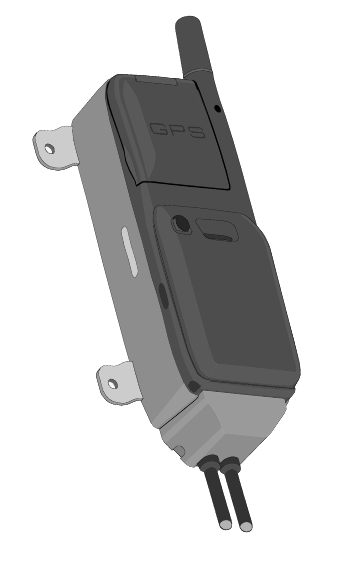
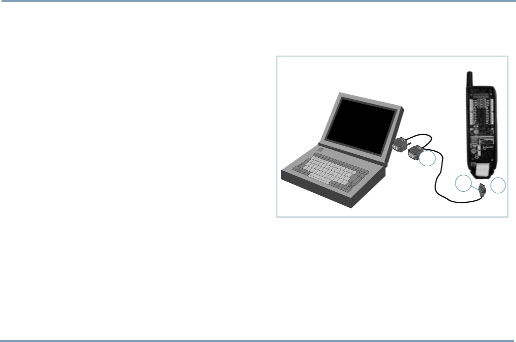
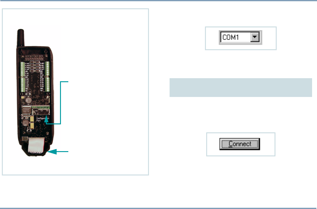
1. The BWTrackbox Data/NMEA cable may contain two
square-end adapters. Plug the data adapter (1) into a
serial port. Serial ports are located at the back panel of
your computer.
2. Next remove the back cover of the device by screwing it
off. Plug the flat end of the BWTrackbox cable (2) in
the configuration port of the device. Make sure the re-
lease button (3) is facing up.
1
2
3
THE BENEFON CONFIGURATOR SOFTWARE FOR TRACKBOX 9
PART A: CONFIGURING SETTINGS FOR THE TRACKBOX
3. Open the Benefon Configurator.
4. Choose the correct serial port from the toolbar: Click
the pop-up menu and highlight the desired port.
Or, choose Settings from the Edit menu. Select the De-
fault communication port by clicking the check box. Click
OK to exit the menu.
5. Double-click the main node My Benefon. Or, double-
click the Trackbox icon. Or, choose Connect from the
Mobile menu. Or, click the button Connect located on
the toolbar.
6. The software establishes a connection to the device and
renames My Benefon node according to the type and the
model of the device, in this case Trackbox.
In order to transfer configura-
tions made by Benefon Config-
urator, the BWTrackbox cable
must be plugged in the de-
vice´s configuration port.
The configuration port is lo-
cated inside the device, in the
lower part of the accessory
module.
Only in case the BWTrackbox
cable is intended for continu-
ous use, you may pierce a hole
to the elastomer for the cable
inlet. Otherwise, leave it intact
for improving dust and water
protection.
THE CONFIGURATION PORT
THE MAIN IDEA IS THAT THE PORT SELECTED IN SOFTWARE
MATCHES WITH THE PORT, THE DATA ADAPTER IS PLUGGED IN.

PART A: CONFIGURING SETTINGS FOR THE TRACKBOX
10 THE BENEFON CONFIGURATOR SOFTWARE FOR TRACKBOX
7. At the same time, the software reads data from the device
and loads it in the display. The data contains currently
existing settings and menus from the device. These set-
tings and menus are shown as sub-nodes, such as User
settings, and Telematics settings. The nodes are struc-
tured as the Benetree on the left side of the display.
8. If the software requests security code while loading the
settings, you must key in the code and press Ok. For
more information on security code, see SECURITY CODE
ON PAGE 48.
9. Click the name label Trackbox. The sub-nodes will be
displayed as icons on the working area, i.e. the Docu-
ment window, on the right.
10.You can select the desired sub-node/icon by clicking it.
The data fields will be displayed.
Loading settings from the Trackbox
to the software
As you connect the device to the software, all current set-
tings in the Trackbox are copied to the software.
To load only part of the settings to the software, choose Con-
figurator from the Edit menu (before pressing Connect but-
ton). Check the desired setting groups - the groups are
shown in the Mobile phone start up tasks. Click Ok while the
dialog box is displayed.
Unloaded settings can be loaded afterwards in the same ses-
sion by choosing Open NNsettings from the Mobile menu.
Saving settings in a computer disk
1. If the device is not currently connected to the software,
you can still make "off-line" configurations, save them
and transfer them to the device afterwards. When work-
ing this way, data fields are available for editing via My
computer node.
2. To save data in a computer disk, choose Save as... from
the File menu.
3. Select the destination drive and folder, and rename the
file the way you like. Click Save. The software stores all
data fields that the chosen node, e.g. User settings, con-
tains.
TIP
IT IS ADVISABLE TO ALWAYS SAVE THE SETTINGS IN THE COMPUTER DISK.
THIS WAY, THE READY-MADE SETTINGS CAN BE EASILY RECALLED AND
CHECKED AT ANY TIME NEEDED, EVEN WHEN THE DEVICE IS FAR AWAY.
WHEN THE SETTINGS ARE STORED IN THE COMPUTER AS A NORMAL
FILE, COPYING THEM TO OTHER SIMILAR DEVICES, OR MAKING
CHANGES TO THEM SHOULD BE QUITE EASY.

THE BENEFON CONFIGURATOR SOFTWARE FOR TRACKBOX 11
PART A: CONFIGURING SETTINGS FOR THE TRACKBOX
Changing default mobile phone
When any Benefon phone (or device) is connected to the
Benefon Configurator, the software identifies it automatical-
ly, and offers you the correct data fields for editing.
To make off-line configuration for some other Benefon
phone (e.g. Esc!) when the phone is currently unavailable,
you need to change the default mobile phone in Benefon
Configurator.
1. Change the default Benefon mobile phone by selecting
Configurator... from the Edit menu, or highlighting the
desired phone model from the pop-up menu, located on
the toolbar.
2. Now the data fields of this "new" phone model are avail-
able and can be opened from the My Computer node on
the left.
3. Click the desired node, e.g. User settings, press the
mouse´s right button and select New >Ok.
4. Similarily, you can close the file which is not needed any
more by clicking it, pressing the mouse´s right button
and selecting Close.
Transferring settings from the
software to the Trackbox
While the Benefon Configurator is connected to the Track-
box, you can save data in the Trackbox.
1. First open the Benefon Configurator document which
content you want to save in the Trackbox.
Settings which are previously stored in a computer disk
can be recalled by choosing Open from the File menu, or
pressing the corresponding function icon on the tool-
bar.
2. Choose Save To Mobile from the File menu.
Or, click the function icon on the toolbar.
When transferring data to the device, the previous data is re-
placed with the new data.

PART A: CONFIGURING SETTINGS FOR THE TRACKBOX
12 ACTIVATING NEW FEATURES
Disconnecting the Trackbox
from the software
1. Choose Disconnect from the Mobile menu.
Or, click the button Disconnect on the toolbar.
2. Press and hold down the release button while removing
the BWTrackbox cable from the device. (The release but-
ton is located on the top of the flat end of the BWTrack-
box cable.)
3. In case the inlet for the BWTrackbox cable is pierced,
but the cable is taken off, the hole must be covered with
some waterproof material, such as a piece of firm tape or
silicon. This needs to be done for improving water pro-
tection.
4. Screw the back cover back in.
ACTIVATING NEW FEATURES
Some of the new features are sold separately, they are not
included in the basic 2.1 software package. Such feature is,
e.g. Encryption.
When you purchase some new features, a Service activation
key is provided to you by the dealer or the manufacturer.
The key is needed for activating the features.
Activation can be easily done with the Benefon Configura-
tor. Activation can also be done via MPTP messaging. For
more information on MPTP commands, see the separate Mo-
bile Phone Telematics Protocol (MPTP) document.
1. First make sure, the phone has a cable connection to the
Benefon Configurator.
2. Click Connect.
3. Select Save activation key from the Mobile menu.
4. Key in the Service activation key.
5. Click Save.
6. Click Disconnect.

SHORT MESSAGES 13
PART A: CONFIGURING SETTINGS FOR THE TRACKBOX
SHORT MESSAGES
In order to read, write, send and receive normal short mes-
sages via the Trackbox, the Trackbox must be connected to
an external device.
The device attached to the Trackbox can be e.g. a computer,
a laptop or a palm computer. Since the Trackbox lacks the
keyboard and screen, the external device must be provided
with these. The physical connection is established with the
BWTrackbox cable.
A suitable software, for example the Benefon Configurator,
is needed for the communication as well.
Reading and editing existing
messages
1. Open the Benefon Configurator.
2. Double-click the icon SMS messages.
Messages are listed and can be read.
Editing: Double-click the message you want to edit. Edit text
and other details in the SMS edit buffer. Click Ok when
ready.
Deleting a short message
To delete a short message, highlight the message and
choose Sms, Delete message from the Edit menu.
Or, select Delete by pressing the mouse´s right button.
PART A: CONFIGURING SETTINGS FOR THE TRACKBOX
14 SHORT MESSAGES
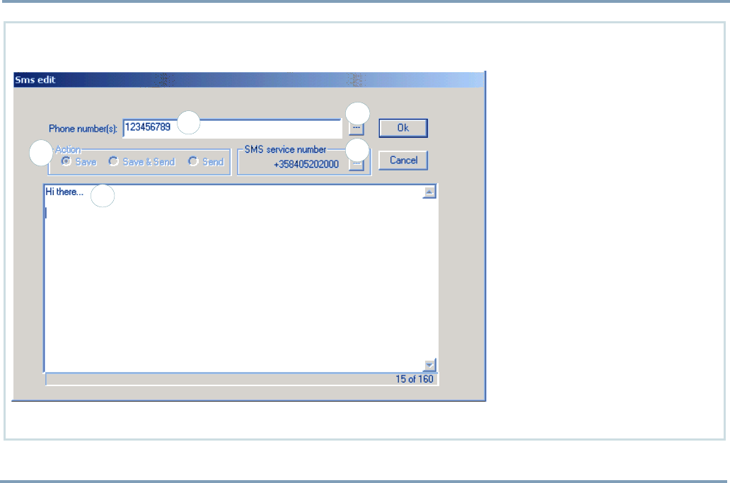
1. Choose Sms, New message from
the Edit menu. The SMS edit
buffer will be displayed.
2. Key in the message text (1) and
the recipient´s number(2). By
clicking the square next to the
number (3), the recipient´s
number can be fetched from the
Phone book, assuming the num-
ber is found on SIM.
3. Make sure, the Sms service num-
ber is correct. The number can
be changed by clicking the
square next to it (4). By select-
ing the option SIM card default,
the SMS service number will be
picked up from the SIM card. If
the SIM card does not contain
the SMS number, select the op-
tion Own and key in the SMS ser-
vice number.
4. Select the desired Saving/Send-
ing option by checking one of
the Action boxes (5). Complete
the message by pressing Ok.
3
2
1
4
5
Writing and sending a short message
PHONE BOOKS 15
PART A: CONFIGURING SETTINGS FOR THE TRACKBOX
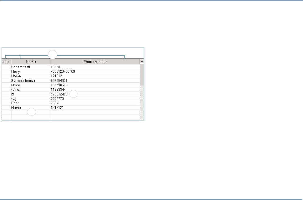
PHONE BOOKS
As you open the Phone books, the memory entries stored on
the SIM card are listed and can be processed. Index number
stands for memory slot number.
Editing and adding an entry
1. To edit details of an entry, click the desired entry . To
add a new phone book entry, click a blank line (1).
2. Key in the name and number(2).
3. By pressing Tab on the keyboard you can move from a
data field to another.
Deleting entries
1. To delete a phone book entry, click the desired entry.
2. Press Delete on the keyboard. You can also choose the
command Delete from the Edit menu, or by clicking the
mouse´s right button.
Arranging entries
Arrange the phone book by Index, Name, or Number (3) ei-
ther by
- clicking the title
- choosing the option from the Edit menu
- clicking the mouse´s right button.
•View by: This option rearranges the phone book tempo-
rarily. When transferring the phone book data back to the
phone, the data will be arranged by the old order.
•Sort by: This option rearranges the phone book perma-
nently. When transferring the phone book data back to
the phone, the data will be arranged by the new order.
2
3
1
PART A: CONFIGURING SETTINGS FOR THE TRACKBOX
16 USER SETTINGS
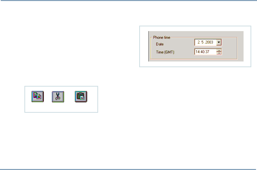
Moving and copying entries
1. To move or copy a phone book entry to another slot,
click the desired entry.
2. Press Ctrl+C (for copy) or Ctrl+X (for cut) on the key-
board. Click the destination line and press Ctrl+V (for
paste) on the keyboard.
You can also choose the commands Copy, Cut and Paste
from the Edit menu, or by clicking the mouse´s right but-
ton.
Or, you can click the corresponding function icons on
the toolbar.
3. If the destination line is reserved, you also need to con-
firm, whether to overwrite the old information or not.
- To overwrite the old information, click Yes in the dia-
log box.
- To preserve the old information and transfer the new
information to another, free slot (Index number), click
No in the dialog box.
USER SETTINGS
Phone time and date
Time and date can be set in the Benefon Configurator. Key
in the time and date in the GMT format (“Greenwich Time”).
Date and time can be selected by clicking the arrows, as
well.
Time stamps associating MPTP messages are displayed in the
GMT format, as well.
Activity timer
Device can be configured to update its position e.g. once a
day and report it to the service center.
Activity timer can also be used to wake up the device peri-
odically to check if there are any incoming messages. If there
are no messages, the timer will return to sleep for the next
wake-up.
Power up/down cycle is reasonable for saving power, espe-
cially in case the device is a plain battery model.
Copy Cut Paste
USER SETTINGS 17
PART A: CONFIGURING SETTINGS FOR THE TRACKBOX
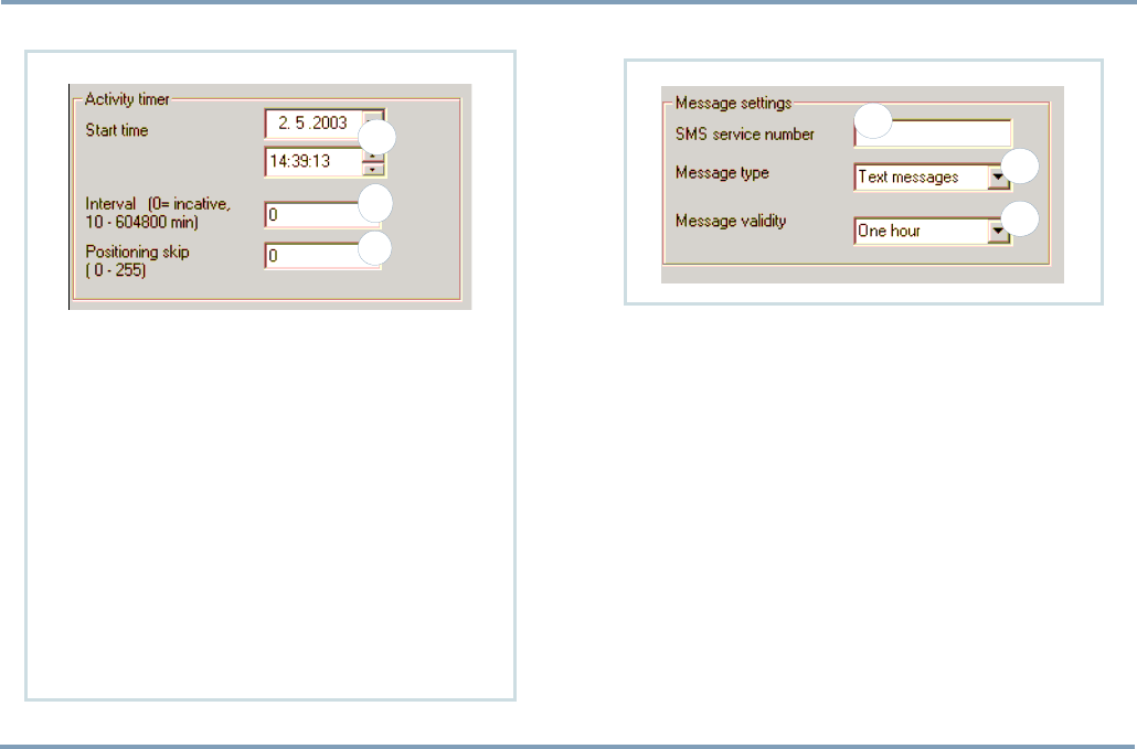
SETTING THE ACTIVITY TIMER Message settings
SMS SERVICE NUMBER
You can store the SMS service number (1), which is needed
for sending normal short messages and telematics protocol
messages.
The number must be set correctly, otherwise sending short
messages is not possible.
The SMS service number can be found e.g. in the manual of
your local network operator.
However, if you are supplied with a separate SMS service
number for telematics protocol messages, you may store the
number in the Protocol settings data field. For more infor-
mation, see GENERAL TELEMATIC SETTINGS ON PAGE 26.
Configuring separate SMS service number for protocol mes-
sages is recommended in case the Activity timer is used (see
above).
1
2
3
1. Start time: Key in the date and time, when the
timer is switched on for the first time. Start
time can be selected by clicking the arrows
(1), as well.
2. Interval: Key in the interval for wake-up (2). If
the interval is set to zero, the timer is NOT in
use.
3. Positioning skip: It may not be necessary to de-
termine current position each time when the
timer is turned on. By setting a value N for the
position skip (3), the device can be pro-
grammed to only determine the position every
Nth time the timer is turned on.
3
2
1
PART A: CONFIGURING SETTINGS FOR THE TRACKBOX
18 USER SETTINGS
MESSAGE TYPE
You can determine what kind of a message you are process-
ing. You can choose the message type from these: Text, Fax,
X400, Email, Ermes, or Data.
When using the device for normal or MPTP messaging, click
the arrow and highlight Text for message type (2).
MESSAGE VALIDITY TIME
You can select the length of validity for normal SMS messag-
es, i.e. for how long the SMS messages are stored in the serv-
er of the operator.
You can choose the message validity from these: 1 hour, 6
hours, 24 hours, 1 week or Maximum time.
Click the arrow and highlight the desired option (3).
NOTE: The length of validity for telematics protocol messag-
es is selected in General telematic settings. For more informa-
tion, see GENERAL TELEMATIC SETTINGS ON PAGE 26.
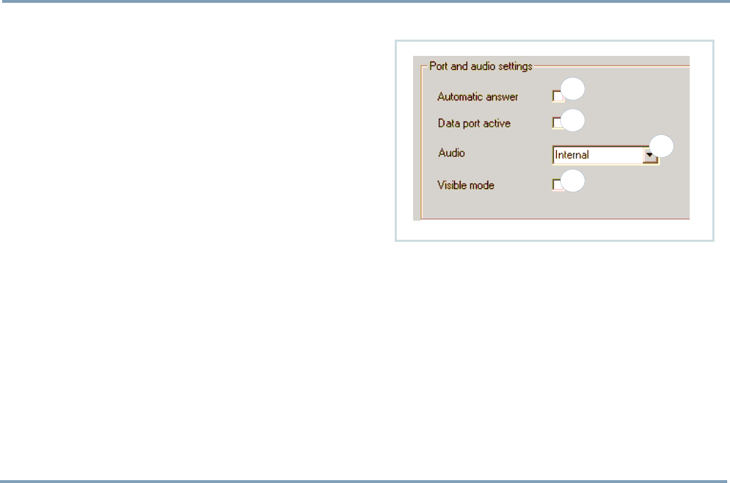
Port and audio settings
AUTOMATIC ANSWER
The automatic answer function can be turned on or off (1).
•If the Automatic answer is turned on (the box is checked),
a voice call to the device from any number is possible.
•If the Automatic answer is turned off (the check box is left
blank), making a voice call to the device can only be done
from a number listed as an allowed caller. Allowed
callers are stored in the General telematics settings. For
more information, see GENERAL TELEMATIC SETTINGS ON
PAGE 26.
1
2
3
4

USER SETTINGS 19
PART A: CONFIGURING SETTINGS FOR THE TRACKBOX
The device contains a built-in microphone. By making a call
to the Trackbox, the caller (e.g. service center) can listen in
the Trackbox and its surroundings. After certain number of
rings, the device answers an incoming call automatically by
opening audio connection.
DATA PORT ACTIVITY
Data port setting must be turned on in case the Trackbox is
needed for data transfer or connected to some external de-
vice.
Turning the data port off decreases power consumption
(2).
•To turn the data port on, check the box.
•To turn the data port off, leave the check box blank.
AUDIO
•Internal: The device contains an internal microphone and
uses it.
•External: Audio comes from some external device via the
configuration port.
Click the arrow and highlight the currently used option (3).
VISIBLE MODE
The device can be set to operate
•In visible mode (the box is checked) or
•In invisible mode (the box is left blank).
In Visible mode the LEDs are lit as described in the Track-
box Installation Guide.
Invisible mode is for making the device more difficult to de-
tect (4). In invisible mode only some of basic LED patterns
are lit, e.g. powering up/down. This way e.g. sending emer-
gency messages can be done very discreetly.
PART A: CONFIGURING SETTINGS FOR THE TRACKBOX
20 USER SETTINGS
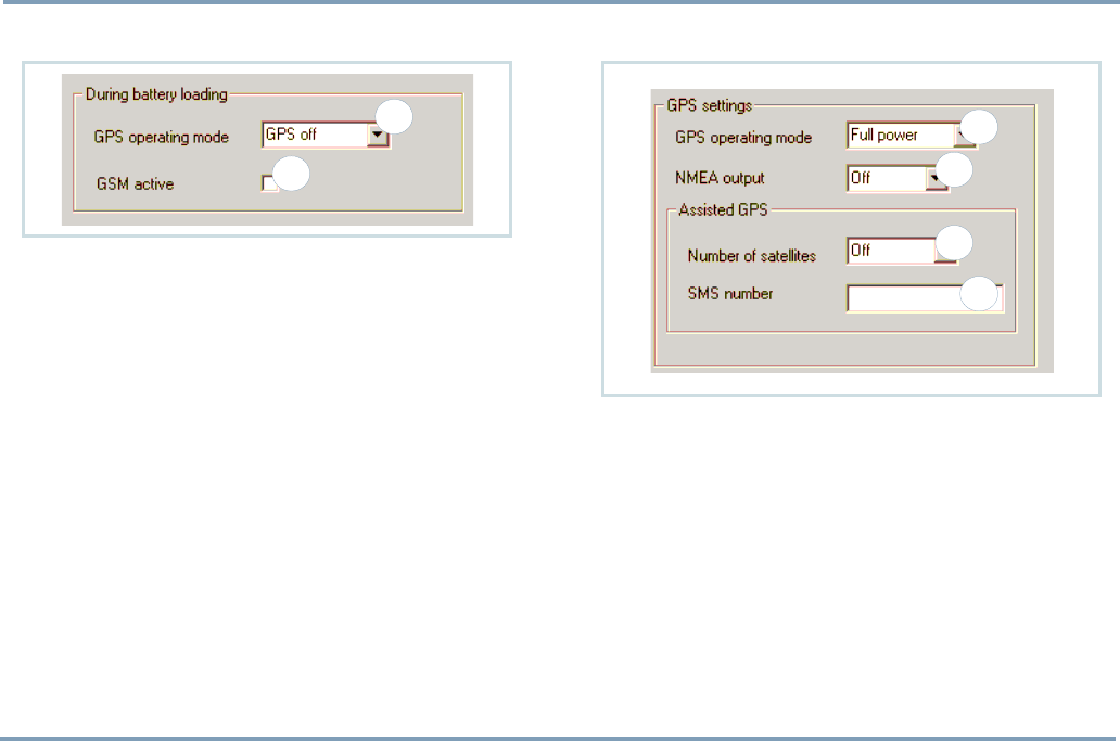
Settings during battery loading
GPS OPERATING MODE
You can select, which one of the GPS power modes is on
while the device is being charged (1).
Set the GPS off, in case
•the time reserved for charging is quite short or
•GPS functions are not needed during charging process.
By selecting No change, the GPS mode remains in the previ-
ously configured mode.
GSM ACTIVATION
You can select, whether the GSM is turned on or off while
the device is being charged (2).
In case the GSM functions are needed even during the
charging, this setting must be turned on: By checking the
box, the GSM is activated during charging.
GPS settings
GPS OPERATING MODE
The GPS receiver in the Trackbox uses power saving options
for ensuring maximum battery capacity.
The GPS receiver has three modes (1):
•Off
•Low Power with the power saving option
- the time needed for position fix depends on condi-
tions. If the GPS does not manage to calculate the posi-
tion, it will fall asleep for a while and retry to calculate
the position later on.
•Full power without the power saving option.
2
11
2
3
4

USER SETTINGS 21
PART A: CONFIGURING SETTINGS FOR THE TRACKBOX
Operating mode depends on the way, the device is used.
Autonomous system, i.e. a plain battery model, normally
uses either Low Power or Off mode, while a device with con-
stant power supply uses Full Power mode (i.e. the standard
and I/O models).
NMEA OUTPUT
The NMEA port output can be turned on or off (2). This de-
vice supports a subset of NMEA 0183 v2.0 output protocol,
which is used for transferring position data between the de-
vice and a navigation system, such as a Search and Rescue
application. For the connection you also need a BWTrack-
box Data/NMEA cable (an accessory).
- By selecting Off, you will turn the NMEA output port
off.
- By selecting a transferring speed you will turn the
NMEA output port on.
When the NMEA output is turned on, the device will con-
sume slightly more power.
ASSISTED GPS (AGPS)
Trackbox has capability to receive assistance to the GPS re-
ceiver in order to speed up the initial position calculation.
This is very useful feature if the device is in poor satellite
coverage.
Assistance can be supplied over the Mobile Phone Telemat-
ics Protocol in a binary coded protocol message. The mes-
sage will contain ephemeric and almanac data which is
based on a rough position calculated by e.g. GSM network
parameters (Cell-ID, CI-TA etc). The assisted GPS is sup-
plied from a third party station server.
Using the AGPS does NOT affect the accuracy of the posi-
tion. If the last position fix is deemed to be too old, and the
AGPS is set, the AGPS feature is automatically used to speed
up the position determination.
The cost of the AGPS service is determined on the contract
of the service provider.
You can specify settings for ordering assisted GPS informa-
tion from a service provider.
•Number of satellites: Select the number of satellites (3).
However, please note that the more satellites selected,
the faster the service but the higher the charge.
•SMS number: Key in the SMS number of the AGPS service
(4).
PART A: CONFIGURING SETTINGS FOR THE TRACKBOX
22 TELEMATIC SETTINGS
TELEMATIC SETTINGS
Tracking settings
1
a
b
2
3 4
b
a
a
b
c
d
c
b
a

TELEMATIC SETTINGS 23
PART A: CONFIGURING SETTINGS FOR THE TRACKBOX
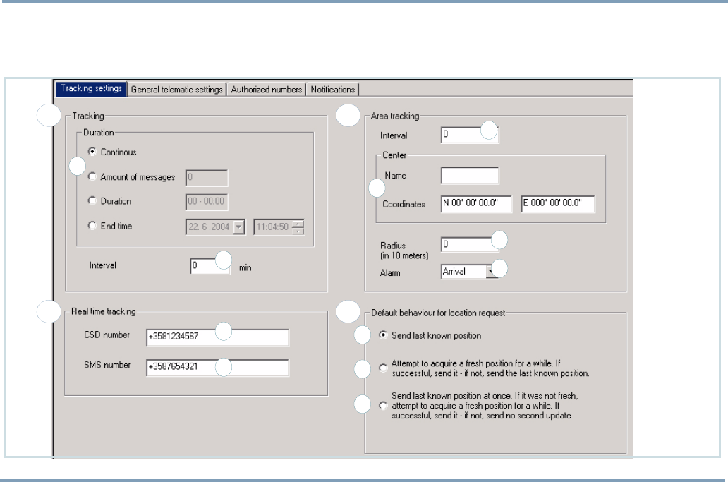
TRACKING
Tracking is remotely controlled by the service center. When
the tracking function is turned on, the position information
is sent to the service center several times in sequence.
If the device is temporarily switched off, battery is removed,
or the power supply is some other way disconnected, the
tracking record (e.g. amount of messages) will be reset and
start from the beginning.
Essential phone numbers, such as Service center number and
SMS service number, must be configured in the device. In the
Benefon Configurator, these numbers can be set in the Gen-
eral telematic settings. For more information, see GENERAL
TELEMATIC SETTINGS ON PAGE 26.
Duration
You can select, for how long or on what terms tracking will
be on (1a). After that, the tracking will be turned off auto-
matically.
Only one of these options can be turned on at once.
•Continuous: The tracking will be turned on until further
notice. !Deactivation message must be sent separately.
•Amount of sent messages: Tracking will be on until
defined amount of messages has been sent to the service
center. Key in the amount.
•Duration: Tracking will be on for a period of time. Key in
how many days, hours and minutes the tracking should be
on.
•End time: Tracking will be on until the end time is
reached. Key in the date and time, the tracking should be
turned off. Date and time can be selected by clicking the
arrows, as well.
Interval
The given interval, e.g. 60 minutes, indicates that the device
will send its position to the service center at intervals of 60
minutes. Key in the tracking interval in minutes (1b).
Activation
Make sure all the required settings for tracking are complet-
ed before activating the function. Such settings are, e.g. du-
ration and interval.
New settings can be applied only while the tracking is deac-
tivated.
You can activate tracking by sending a specific MPTP mes-
sage to the device.

PART A: CONFIGURING SETTINGS FOR THE TRACKBOX
24 TELEMATIC SETTINGS
AREA TRACKING
Area tracking is remotely controlled by the service center (or
some other authorized number). When the area tracking is
turned on, the position information will be sent to the ser-
vice center only when the device is moving in or out of the
pre-defined area.
The area can be determined by keying in a center point and
a radius of an area. The area tracking does not contain the
duration option, i.e. the area tracking will never be turned
off automatically.
Essential phone numbers, such as Service center number and
SMS service number must be configured in the device. In the
Benefon Configurator, these numbers can be set in the Gen-
eral telematic settings. For more information, see GENERAL
TELEMATIC SETTINGS ON PAGE 26.
Interval
The given interval, e.g. 60 minutes, indicates that the device
will send its position to the service center at intervals of 60
minutes, but only in case the device is located outside of the
determined area.
Key in the interval for area tracking in minutes (2a).
Center point
Key in the center point name (e.g. Home) and enter coordi-
nates (2b).
Radius
Key in the desired radius in 10 meters (2c). E.g. by entering
5, your actual radius will be set for 50 meters (minimum).
Alarm mode
You can set an alarm to alert when crossing the borderline
of an area (2d).
The alarm can be set to alert either when arriving in or de-
parting from the particular area.
Activation
Make sure all the required settings for area tracking are com-
pleted before activating the function. Such settings are, e.g.
interval, center point, radius and alarm mode (at arrival or
departure).
New settings can be applied only while the area tracking is
deactivated.
You can activate area tracking by sending a specific MPTP
message to the device.

TELEMATIC SETTINGS 25
PART A: CONFIGURING SETTINGS FOR THE TRACKBOX
DEFAULT BEHAVIOUR FOR LOCATION
REQUEST
The device may receive several different messages request-
ing location. Such messages can be, e.g. Location request
(?LOC) messages, or Location history request (?HIS) messag-
es. (For more information on how to create location request
messages, see the separate MPTP document.)
You can define, which way the device responds the location
requests. The message always includes a time stamp indicat-
ing age of the position.
Choose from the options below by checking the corre-
sponding box in the Benefon Configurator.
•Send last known position (4a): When the device receives
the location request, the device immediately recalls the
latest position found in the memory and sends it to the
requesting number. The position can be quite old. If the
device does not have a position at all, the message will be
sent without position.
•Attempt to acquire a fresh position for a while (4b): When
the device receives the location request, the device imme-
diately switches the GPS on (if it is currently off), updates
position, sends it and switches the GPS off. Then the
device returns to normal idle mode. Only in case the posi-
tion update is NOT possible within 3 - 4 minutes, the
device will send the latest position found in the memory
to the requesting number.
•Send last known position at once (4c): When the device
receives the location request, the device immediately
recalls the latest position found in the memory and sends
it to the requesting number. In addition to that, the
device tries to update the position for 3 - 4 minutes. If the
position update succeeds, the new position is sent to the
requesting number, as well.
REAL TIME TRACKING
Real time tracking can be initiated by sending a detailed
MPTP message to the device.
Real time tracking is done via CSD data call. After successful
connection, the device starts to forward NMEA data directly
from the GPS over CSD call.
If sending a CSD call fails, the device will send an SMS mes-
sage informing what went wrong.
•Key in the CSD number (3a). The number must be config-
ured in the device before the function can be used.
•Key in the SMS number (3b). The number must be config-
ured in the device, as well.
PART A: CONFIGURING SETTINGS FOR THE TRACKBOX
26 TELEMATIC SETTINGS
General telematic settings
1
3
4
5
2

TELEMATIC SETTINGS 27
PART A: CONFIGURING SETTINGS FOR THE TRACKBOX
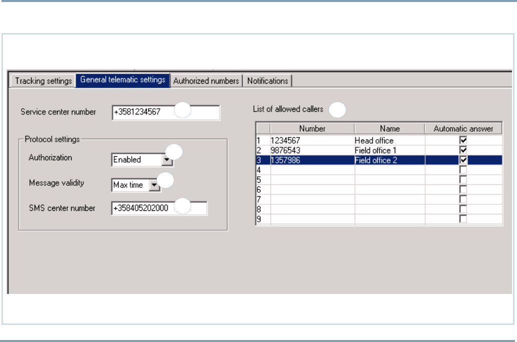
SERVICE CENTER NUMBER
You can change and store the phone number, which is used
for sending telematics protocol messages to the service cen-
ter.
Key in the number for the service center (1).
LIST OF ALLOWED CALLERS
You can set several numbers for allowed callers. You can
also attach the automatic answer function to the desired
numbers.
Allowed callers are the ones, who are permitted to call to
the device at any time: Calls from these specific numbers are
always put through.
Key in the name and the number of an allowed caller (2). If
you want the device to answer automatically to calls coming
from certain numbers, make sure to check those boxes, as
well.
PROTOCOL SETTINGS
Authorization
You can select whether the device receives protocol messag-
es from anyone or only from authorized numbers. Click
the arrow and highlight the desired option (3).
•If the authorization setting is Enabled, only authorized
numbers are valid senders of a protocol message and
reply to the protocol message will be sent back to the
same number.
•If the setting is Disabled, the sender of a protocol message
can be anyone, e.g. the message can be sent from the
Internet or the number can be blank. If the service center
number is set, reply is always sent to the service center. If
the service center number is NOT set, reply is sent to the
sender of a protocol message (assuming the sender´s
number is available).

PART A: CONFIGURING SETTINGS FOR THE TRACKBOX
28 TELEMATIC SETTINGS
Message validity
You can select the length of validity for telematics protocol
messages, i.e. for how long the SMS messages are stored in
the server of the operator (4).
This setting can be used to avoid massive helping efforts in
case an emergency message has been sent a week ago and
there is reason to believe that help is no longer needed.
You can choose the message validity from these: 1 hour, 6
hours, 24 hours, 1 week or Maximum time.
The length of validity for normal SMS messages is selected
elsewhere, in the User settings. For more information, see
MESSAGE VALIDITY TIME ON PAGE 18.
SMS center number
You can set separate SMS center number for the telematics
protocol messages. If the number is not set, the normal
short message service number is used instead.
Key in the SMS center number (5).
TELEMATIC SETTINGS 29
PART A: CONFIGURING SETTINGS FOR THE TRACKBOX
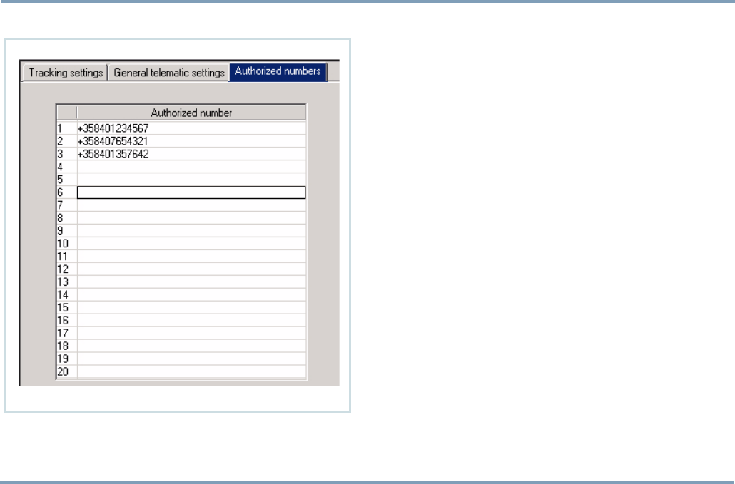
Authorized numbers The device is allowed to respond to protocol messages from
the authorized numbers automatically, at any time.
Authorized numbers are:
•the numbers stored in the Authorized numbers list and
•the Emergency center numbers and
•the Service center number.
For more, see SERVICE CENTER NUMBER ON PAGE 27 and EMER-
GENCY CENTER NUMBERS ON PAGE 32.
NOTE: If the requesting number is unauthorized, sending
response depends on Authorization and Service center num-
ber settings.
•Authorization setting Enabled, -> The device ignores the
request, i.e. does nothing.
•Authorization setting Disabled, Service center number NOT
set ->Response goes to the requesting number.
•Authorization setting Disabled, Service center number is set
->Response always goes to service center.
For more on Authorization setting, see AUTHORIZATION ON
PAGE 27.
PART A: CONFIGURING SETTINGS FOR THE TRACKBOX
30 TELEMATIC SETTINGS
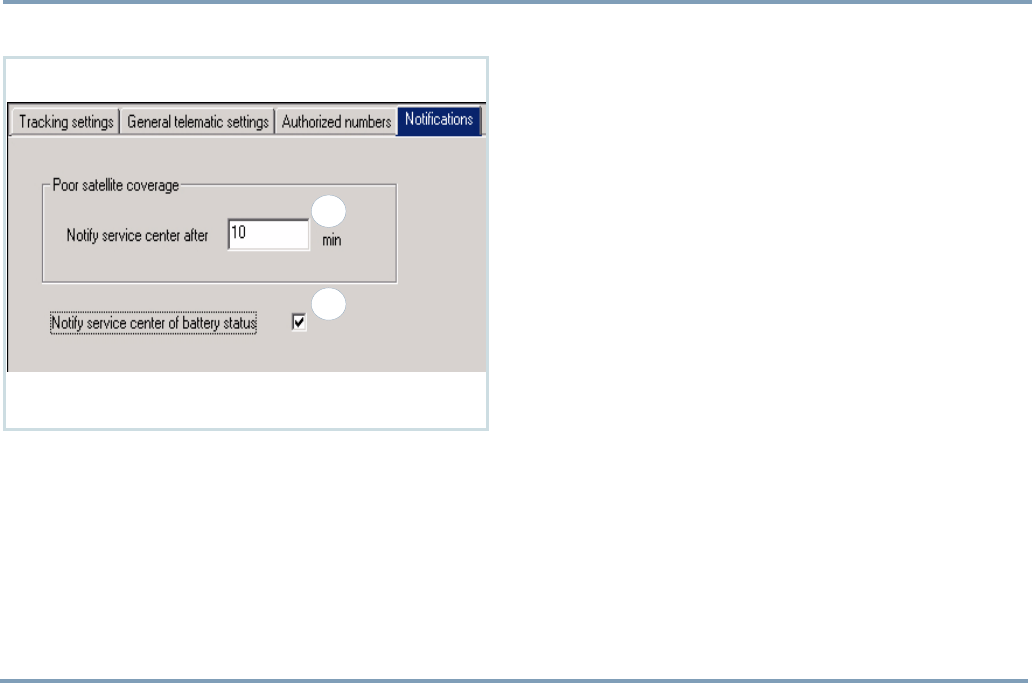
Notifications POOR SATELLITE COVERAGE
Notify service center when satellite coverage drops: The de-
vice can be configured to notify the service center if the sat-
ellites are suddenly dropped and position is lost, e.g. when
entering in a building.
Key in the number in minutes (1).
The timeout indicates, for how long the device is allowed to
stay in poor satellite coverage before sending a protocol
message to the service center - the smaller the number you
set in here, the faster the device will react to lost satellites
and the sooner the notification will be sent.
NOTIFY SERVICE CENTER OF BATTERY
STATUS
By checking the box (2), the service center will be notified
of some events occurred in battery status.
Notifying means sending a protocol message to the service
center, for example in these cases: Low battery, temperature
too warm/too cold for charging or using battery, battery fail-
ure.
1
2
I/O SETTINGS 31
PART A: CONFIGURING SETTINGS FOR THE TRACKBOX
I/O SETTINGS
Emergency settings
2
5
3
1
4
a
ba cb

PART A: CONFIGURING SETTINGS FOR THE TRACKBOX
32 I/O SETTINGS
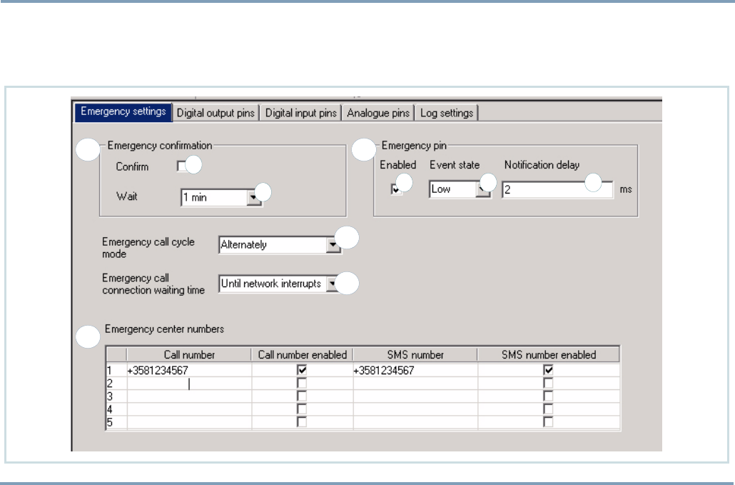
EMERGENCY CONFIRMATION
You can request the emergency center to send a confirma-
tion of the emergency message. The emergency center will
then send the confirmation to the device as soon as it re-
ceives the emergency message. Check the box to enable con-
firmation, or leave the check box blank to disable
confirmation (1a).
You can also specify a waiting time, i.e. for how long a time
the device waits for the confirmation before trying to reach
some other emergency center number. Click the arrow and
highlight the desired option (1b).
EMERGENCY CALL CYCLE MODE
You can define the order for making emergency voice calls
and sending emergency messages while the emergency call
cycle is on (2).
You have two choices:
•Alternately: The device will make a voice call and send an
SMS in pairs according to the list order, starting from the
top.
•First SMS, then calls: As the emergency call cycle is initi-
ated, first the device will send the emergency messages,
after which the voice calls will be made starting from the
top of the list.
EMERGENCY CALL CONNECTION WAITING
TIME
You can define for how long a time the device tries to call a
single emergency center number before moving on to the
next number in the list of emergency center numbers.
Click the arrow and highlight the desired option (3).
EMERGENCY CENTER NUMBERS
The emergency (SOS) messages are sent and emergency
calls are made to the numbers stored in the emergency cen-
ter list (4).
The emergency call (i.e. emergency cycle) can contain both
(voice) calls and messages. Calls can be made to mobile
phone numbers, or normal phone numbers. Messages are
protocol messages sent to mobile phones via SMS. The
emergency message contains both GPS coordinates and
GSM network measurement report.
The numbers are in priority order, starting from the top of
the list. These numbers work as "a chain":
If the first number is unreachable (after two attempts), the
device calls or sends the short message to the second num-
ber. If it is not answered either, the device will go on to the
third number on the list and so on.

I/O SETTINGS 33
PART A: CONFIGURING SETTINGS FOR THE TRACKBOX
The device tries to reach contact with the other numbers
once before moving on to the next number in the list. If
there is still no answer after going through the whole list,
the calling procedure will be started all over. The device
makes three rounds.
Key in the numbers. To enable a number, check the box
which associates the number.
EMERGENCY PIN
Activating emergency pin
•To activate the emergency input pin, check the Enabled
box (5a).
•The input pin is NOT in use when the check box is left
blank. A signal of this pin is not detected at all.
Setting event state
Determine status for the emergency pin. The circuit can be
set for High or Low. Click the arrow and highlight the de-
sired option (5b).
A change in the status causes grounding of a pin. An event
causing this can be, e.g. pressing the emergency switch.
After the change in status is registered, the device will start
an emergency cycle and store the information in the Event
log.
- For more information on Emergency cycle, see EMER-
GENCY CYCLE (I/O MODEL ONLY) ON PAGE 52.
- For more information on Event log, see EVENT LOG SET-
TINGS ON PAGE 43.
Defining notification delay
The device can be configured to allow some millseconds to
pass until the event will be registered or interpreted as a
cause for making an alarm.
Key in the time for allowed delay in millseconds (5c).
PART A: CONFIGURING SETTINGS FOR THE TRACKBOX
34 I/O SETTINGS
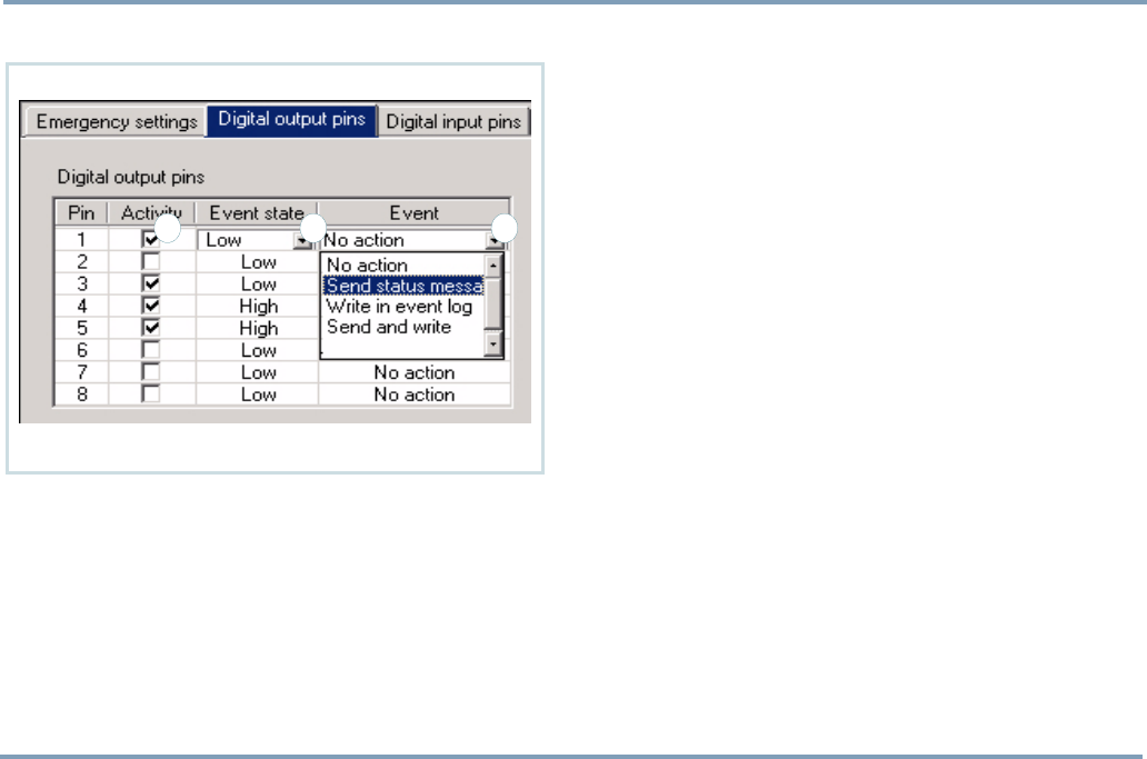
Digital output pins
ACTIVATING DIGITAL OUTPUT PIN
•To activate an output pin, check the Activity box (1).
•NOTE: The output pin is NOT in use when the check box
is left blank. A signal of the pin is not detected at all.
SETTING EVENT STATE
Determine Event state for the digital output pin. The circuit
can be set for High or Low. Click the arrow and highlight the
desired option (2).
A change in the event state causes grounding of a pin. The
change can be done by sending a specific MPTP message to
the device. The desired action can be, e.g. swiching an elec-
tric sauna on remotely.
After the change is registered, the device responds to an
event the way, it is configured in the Event data field (see be-
low).
SELECTING EVENT
You can determine the way, the device responds to an event.
Click the arrow on the Event data field and highlight the de-
sired option (3).
•No action: The device does not send or log anything.
•Send status message: The device sends status message of
the event as a reply to the requesting number.
•Write in event log: The device only writes down the event
in the Event log.
•Send and write: The device sends status message of the
event as a reply to the requesting number and writes
down the event in the Event log.
321
I/O SETTINGS 35
PART A: CONFIGURING SETTINGS FOR THE TRACKBOX
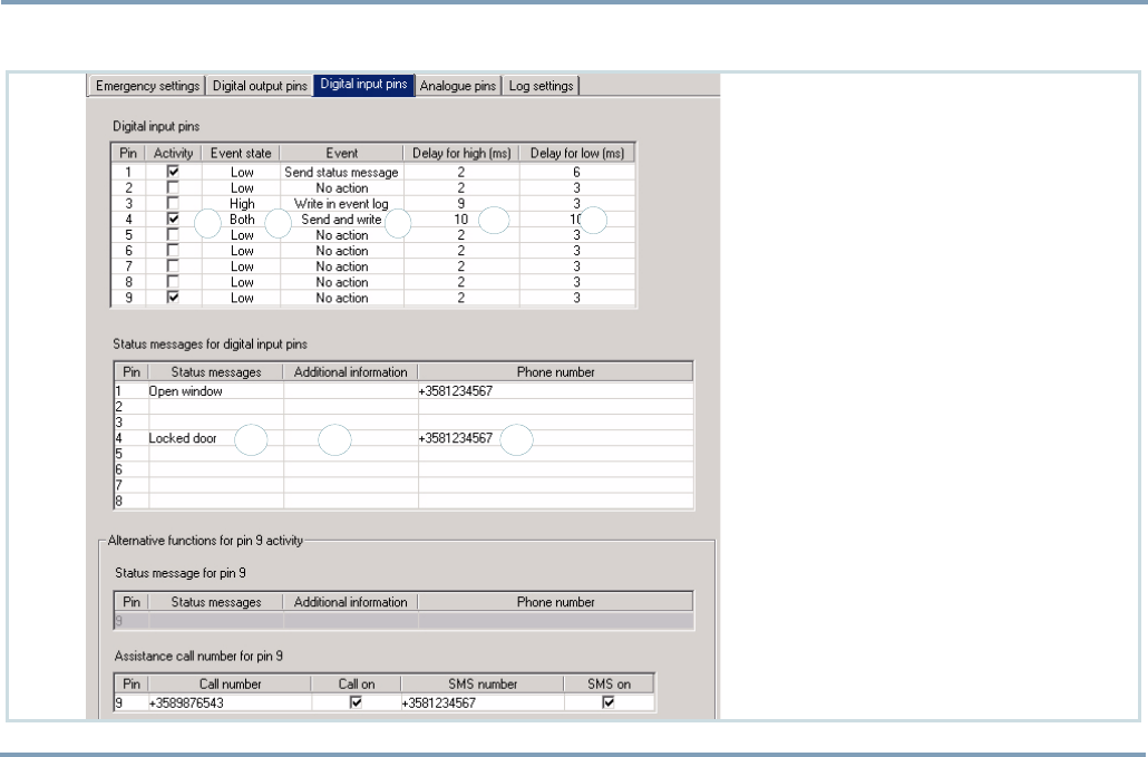
Digital input pins
1
4
3
5
2
6 87

PART A: CONFIGURING SETTINGS FOR THE TRACKBOX
36 I/O SETTINGS
SETTINGS FOR DIGITAL INPUT PINS
Activating digital input pin
•To activate an input pin, check the Activity box (1).
•NOTE: The input pin is NOT in use when the check box is
left blank. A signal of the pin is not detected at all.
Setting event state
Determine Event state for the digital input pin. The circuit
can be set for High, Low, or Both. Click the arrow and high-
light the desired option (2).
A change in the event state causes grounding of a pin. An
event causing this can be, e.g. opening a door, or closing a
door. The Both option means that the change in the event
state is registered for both directions: E.g. the device will re-
sponse whenever a door is opened AND closed.
After the change is registered, the device responds to an
event the way, it is configured in the Event data field.
Selecting event
You can determine the way, the device responds to an event.
Click the arrow on the Event data field and highlight the de-
sired option (3).
•No action: The device does not send or log anything.
•Send status message: The device sends status message of
the event to the corresponding status message number.
•Write in event log: The device only writes down the event
in the Event log.
•Send and write: The device sends status message of the
event to the corresponding status message number and
writes down the event in the Event log.
NOTE: If the status message number is not configured (the
data field is left blank), the status message will be sent to the
service center number. For more information on configur-
ing status messages and their destination numbers, see STA-
TUS MESSAGES FOR DIGITAL INPUT PINS ON PAGE 37.
Defining notification delay
The device can be configured to allow some millseconds to
pass until the event will be registered or interpreted as a
cause for taking an action. In this case an action, such as
sending status messages and/or logging information, would
take place only in case a door is wide open for at least NN
millseconds.
Key in the time for allowed delay (4,5) in millseconds. Delay
can be set separately for High and Low, depending on which
one of the event states is in use. If you have set the pin to
register event states for Both directions, you can set values
for both High and Low.

I/O SETTINGS 37
PART A: CONFIGURING SETTINGS FOR THE TRACKBOX
STATUS MESSAGES FOR DIGITAL INPUT PINS
A status message is a special short message, which includes
the status message text, additional text information and the
last known position (i.e. coordinates and some other MPTP
information). If the current position information is not
available, the previous coordinates will be sent instead.
Message text can contain information on opened or closed
door etc.
Creating status messages
The status messages 1 - 8 are related to digital input pins
1 - 8.
E.g. if you have connected and wired the digital input pin4
to control locking the door, write down the corresponding
information on the fourth row.
•Key in the desired status message text (6) and the phone
number (8) to which this status message will be sent.
•Additional information (7) can - according to your
choice - include details of some sort but the data field can
be left blank, as well.
ALTERNATIVE FUNCTIONS FOR PIN9 ACTIVITY
If Assistance call feature is in use, the digital input pin9 is
reserved for making assistance calls. If the feature is not in
use, the pin9 works like any other digital input pin.
An assistance call can contain a voice call, an sms message,
or both. The assistance (voice) call is an information call,
which is made to specific, pre-configured number. The des-
tination number can be a mobile phone number as well as
any normal phone number. Along with the voice call or in-
stead of it, the device may send its position as a short mes-
sage.
Depending on selected usage, fill in the information:
•When the pin9 is used for sending Status message: Key in
the status message text and the destination number. If the
destination number is not defined, the status message will
be sent to the service center number. Additional informa-
tion is optional.
•When the pin9 is used for making Assistance call: Key in
the assistance voice call and/or SMS numbers. Activate the
number(s) by checking the corresponding Call on/SMS on
box(es).
PART A: CONFIGURING SETTINGS FOR THE TRACKBOX
38 I/O SETTINGS
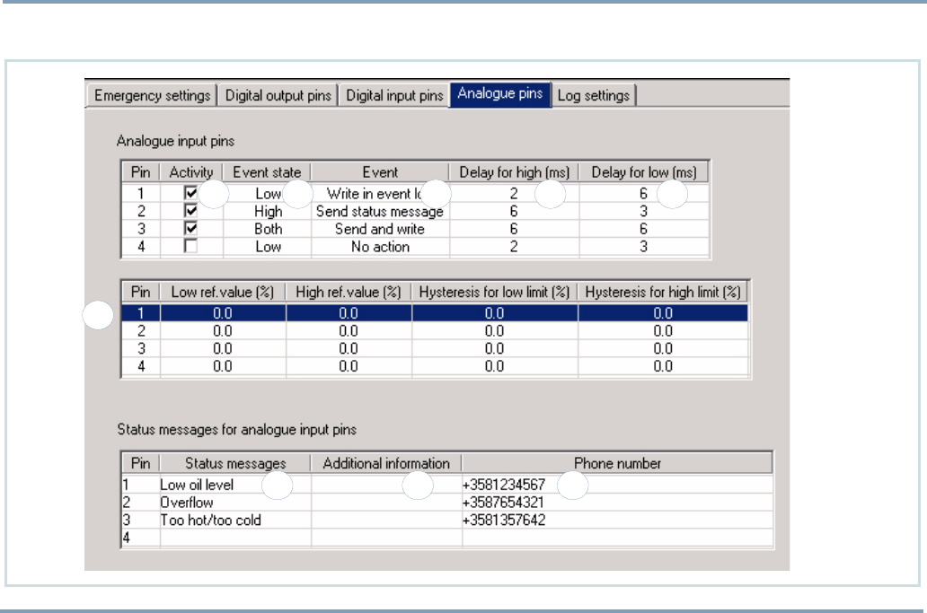
Analogue input pins
87
6
54321
9

I/O SETTINGS 39
PART A: CONFIGURING SETTINGS FOR THE TRACKBOX
SETTINGS FOR ANALOQUE INPUT PINS
Activating analogue input pin
•To activate an analogue input pin, check the Activity box
(1).
•NOTE: The input pin is NOT in use when the check box is
left blank. A signal of the pin is not detected at all.
Setting event state
Determine Event state for the analogue input pin. Event
state can be set for High, Low and Both. Click the arrow and
highlight the desired option (2).
A change in the event state causes grounding of a pin. An
event causing this could be, e.g. a sudden increase/decrease
in liquid level or a crucial change in temperature. The Both
option means that the change in the event state is registered
for both directions: E.g. when the liquid level goes above
AND beyond allowed level.
After the change is registered, the device responds to an
event the way, it is configured in the Event data field (see be-
low).
Selecting event
You can determine the way, the device responds to an event.
Click the arrow on the Event data field and highlight the de-
sired option (3).
•No action: The device does not send or log anything.
•Send status message: The device sends status message of
the event to the corresponding status message number.
•Write in event log: The device only writes down the event
in the Event log.
•Send and write: The device sends status message of the
event to the corresponding status message number and
writes down the event in the Event log.
NOTE: If the status message number is not configured (the
data field is left blank), the status message will be sent to the
service center number. For more information on configur-
ing status messages and their destination numbers, see STA-
TUS MESSAGES FOR ANALOGUE INPUT PINS ON PAGE 40.

PART A: CONFIGURING SETTINGS FOR THE TRACKBOX
40 I/O SETTINGS
Defining notification delay
The device can be configured to allow some millseconds to
pass until the event will be registered or interpreted as a
cause for taking an action. In this case an action, such as
sending status messages and/or logging information, would
take place only in case the temperature exceeds the allowed
temperature and stays up for at least NN millseconds.
Key in the time for allowed delay (4,5) in millseconds. Delay
can be set separately for High and Low, depending on which
one of the event states is in use. If you have set the pin to
register event states for Both directions, you can set values
for both High and Low.
Setting reference values
Threshold values must be set separately for high and low
(6).
•For the pins you have set event state High: Key in High ref-
erence value and Hysteresis for High limits.
•For the pins you have set event state Low: Key in Low ref-
erence values and Hysteresis for Low limits.
•For the pins you have set event state Both: Key in both
Low and High reference values and Hysteresis for Low and
High limits.
STATUS MESSAGES FOR ANALOGUE
INPUT PINS
A status message is a special short message, which includes
the status message text, additional text information and the
last known position (i.e. coordinates and some other MPTP
information). If the current position information is not
available, the previous coordinates will be sent instead.
Message text can contain information on temperature or liq-
uid level changes etc.
Creating status messages
The status messages 1 - 4 are related to analogue input pins
1 - 4.
E.g. if you have connected and wired the analogue input
pin1 to control liquid level, write down the corresponding
information on the first row.
•Key in the desired status message text (7) and the phone
number (9) to which this status message will be sent.
•Additional information (8) can - according to your
choice - include details of some sort but the data field can
be left blank, as well.
I/O SETTINGS 41
PART A: CONFIGURING SETTINGS FOR THE TRACKBOX
SAMPLE CASE 1:
Setting both High and Low
reference values for the an-
alog input pin.
In this sample case the idea
is to keep, e.g. the liquid
level of a container in be-
tween 20 - 80 % of the con-
tainer´s capacity.
High (80%) and Low (20%)
reference values are
threshold values, i.e. alert
limits, which must not be
crossed. If the level goes
clearly above High value or
below Low value, the device
will give alarm of the event.
Hysteresis defines toler-
ance, which is set to allow
minor variations in liquid
level. Only when the level
crosses both borderlines
(reference value and hys-
teresis), the device will give
alarm of the event.
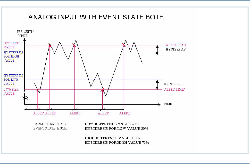
PART A: CONFIGURING SETTINGS FOR THE TRACKBOX
42 I/O SETTINGS
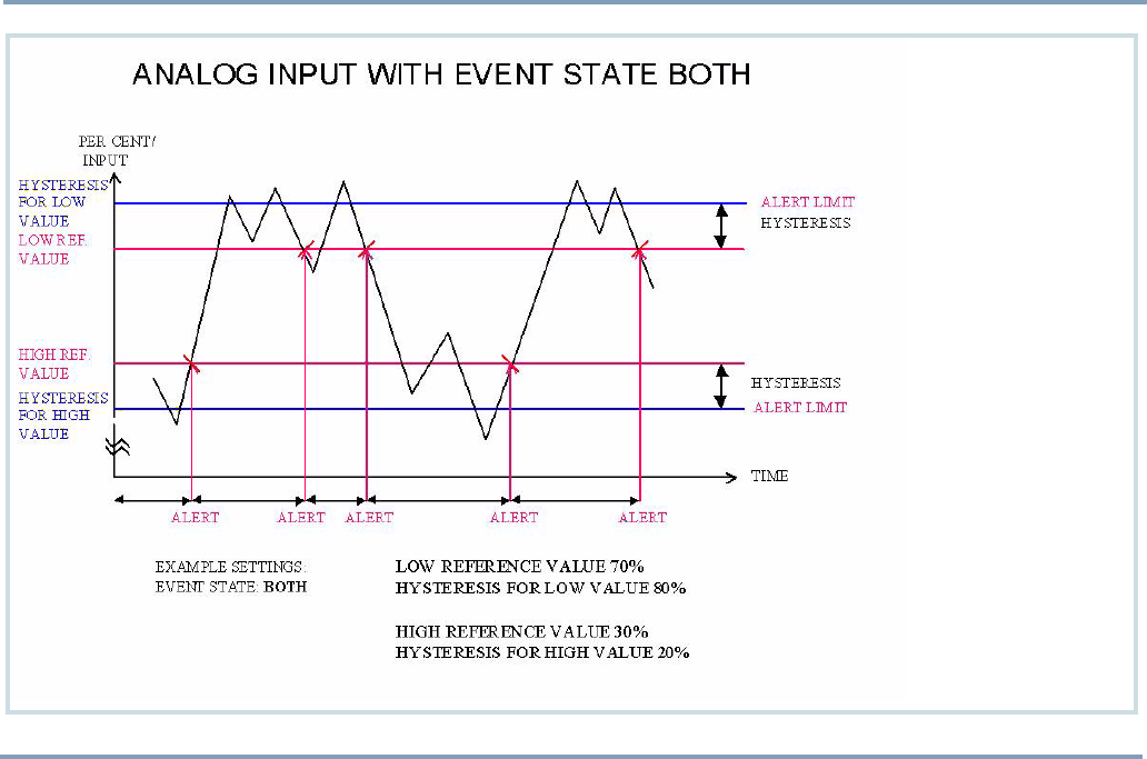
SAMPLE CASE 2:
Setting both High and Low
reference values for the
analog input pin.
In this sample case the
idea is to keep, e.g. the
temperature either above
or below of some value.
Low (70%) and High (30%)
reference values are
threshold values, i.e. alert
limits, which must not be
crossed. If the level goes
clearly above High value,
or below Low value, the
device will give alarm of
the event.
Hysteresis defines toler-
ance, which is set to allow
minor variations in temper-
ature. Only when the tem-
perature crosses both
borderlines (reference val-
ue and hysteresis), the de-
vice will give alarm of the
event.
I/O SETTINGS 43
PART A: CONFIGURING SETTINGS FOR THE TRACKBOX
Log settings
The device can be configured to collect incoming/outgoing
data from the I/O pins. The device can also be configured to
store plain positions at defined intervals.
Stored data may contain information on battery level, posi-
tion, date and time, speed, direction, triggered event, event
value, ID, type and so on.
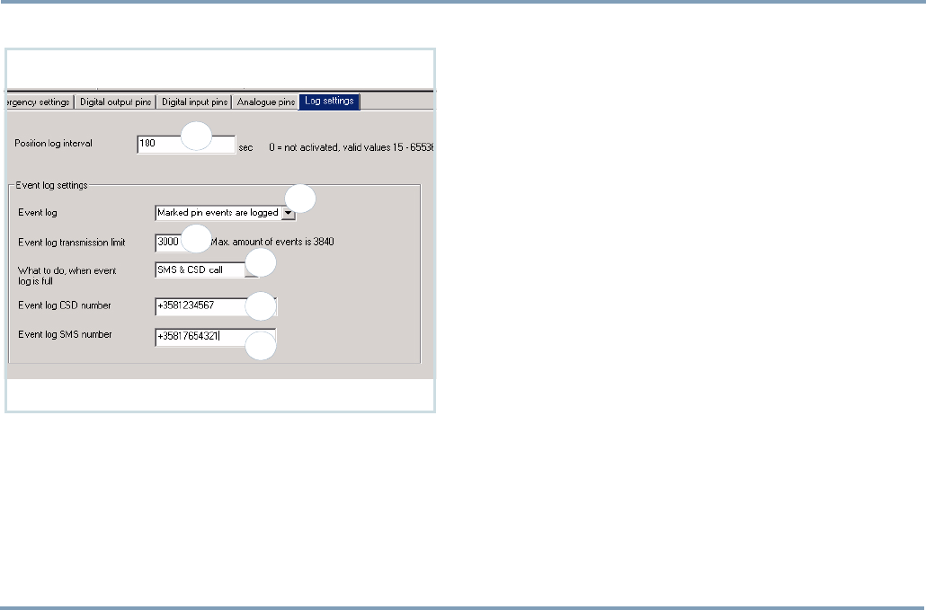
POSITION LOG INTERVAL
With the position log interval setting, you can determine the
device to store plain positions at pre-defined intervals. This
way positions are calculated and logged more frequently.
Key in the interval in seconds (1). The interval can be set be-
tween 15 and 65536 seconds. If the value is set to zero, the
position log interval is NOT in use.
EVENT LOG SETTINGS
Activating Event log
Click the arrow and highlight the desired option (2).
•No pin events are logged: The device does NOT gather any
pin information in the Event log.
•All pin events are logged: The device will gather pin infor-
mation from all active pins, despite of the options
selected in the Event data fields.
•Marked pin events are logged: The device will gather pin
information from a pin under these conditions: The Activ-
ity box is checked and Event data field is set to Write in
event log, or Send and write.
1
2
3
4
5
6

PART A: CONFIGURING SETTINGS FOR THE TRACKBOX
44 I/O SETTINGS
Event log transmission limit
The limit (3) indicates, how much space is left for events in
the Event log. The smaller the number you set in here, the
more stuffed the log will be before the device sends the log
or even informs of it.
NOTE: Event log limit value depends on Flash memory ca-
pacity of the device model, e.g. Normal 3840 or Extended
7936 pieces at maximum.
The limit also works as a trigger: When the limit is reached,
the device will take action, e.g. send the log information as
a CSD data call to the pre-configured CSD number. Action
depends on configuration made in the What to do, when
event log is full (see below).
What to do when event log is full
With this setting (4) you can define how to proceed when
the log is about to reach limit. You can choose from these
options:
•No notification: No action at all. The log does nothing else
but preserve the already collected log information (if the
Event log is in use). When the log is full, there is no space
for new log information. The service center will NOT be
informed of this at all.
However, it is still possible to recall (or clear) the log
"over the air" by sending a specific MPTP message sepa-
rately to the device.
•CSD call: When the log reaches the limit, the log informa-
tion will be sent automatically as a CSD call to a pre-con-
figured CSD number. There are three sending attempts.
•SMS notification: When the log reaches the limit, the
device will send an SMS notification informing that the
log is almost full. A new log information cannot be stored
unless the old log has been separately cleared or recalled
by the service center or an authorized number.
•SMS & CSD call: When the log reaches the limit, an SMS
notification will be sent informing the service center of an
incoming log transfer. Then the log information will be
sent automatically as a CSD call to a pre-configured CSD
number. There are three sending attempts.

I/O SETTINGS 45
PART A: CONFIGURING SETTINGS FOR THE TRACKBOX
CSD number
Key in the CSD data call number (5). The number is needed
for transferring log from the device to the receiving mobile
phone. The receiving phone must be connected to the com-
puter.
NOTE: In order to use the CSD data connection, you need
to insert a specific SIM card (equipped with data feature), in
the receiving mobile phone. Data feature includes a sepa-
rate data call phone number, i.e. CSD number, for data re-
ception. In order to get this feature, please contact your
network operator.
For more information on receiving the log, see REMOTE
TRANSFER ON PAGE 60.
SMS number
Key in the SMS number (6).
The number is needed in order to inform and warn the ser-
vice center of some events and errors which may occur on
the way.
TRANSFERRING OR CLEARING THE LOG
In order to be able to collect new log information, the old log in-
formation must be transferred or cleared. There are several ways
to do it:
1. A CSD call: If the selected procedure option contains a CSD
call, the old log will be cleared automatically after successful
CSD call.
- However, the CSD data call can fail for reasons, such as:
CSD number is not set, establishing data call connection
is failed, ongoing data call is disconnected, or an emer-
gency call (or some other primary function) is activated
during the data call transmission.
- If the CSD call fails after three attempts, an SMS will
be sent to the service center informing of reasons for
failure.
2. An MPTP message: Clearing or transferring the log can also
be done individually, by sending a specific MPTP message to
the device, after which the device sends or deletes the log.
- Proceed this way if the CSD call fails after three at-
tempts, or the selected procedure option does not con-
tain a CSD call at all.
3. Benefon Configurator: The Event log information can also
be transferred or cleared locally, by using the Benefon Con-
figurator software and BWTrackbox cable connection.
- You may proceed this way if you can wait until the de-
vice "returns home".
For more information on entire process, see also RECALLING
EVENT LOG (I/O MODEL ONLY) ON PAGE 59.
PART A: CONFIGURING SETTINGS FOR THE TRACKBOX
46 WAYPOINT TRACKING
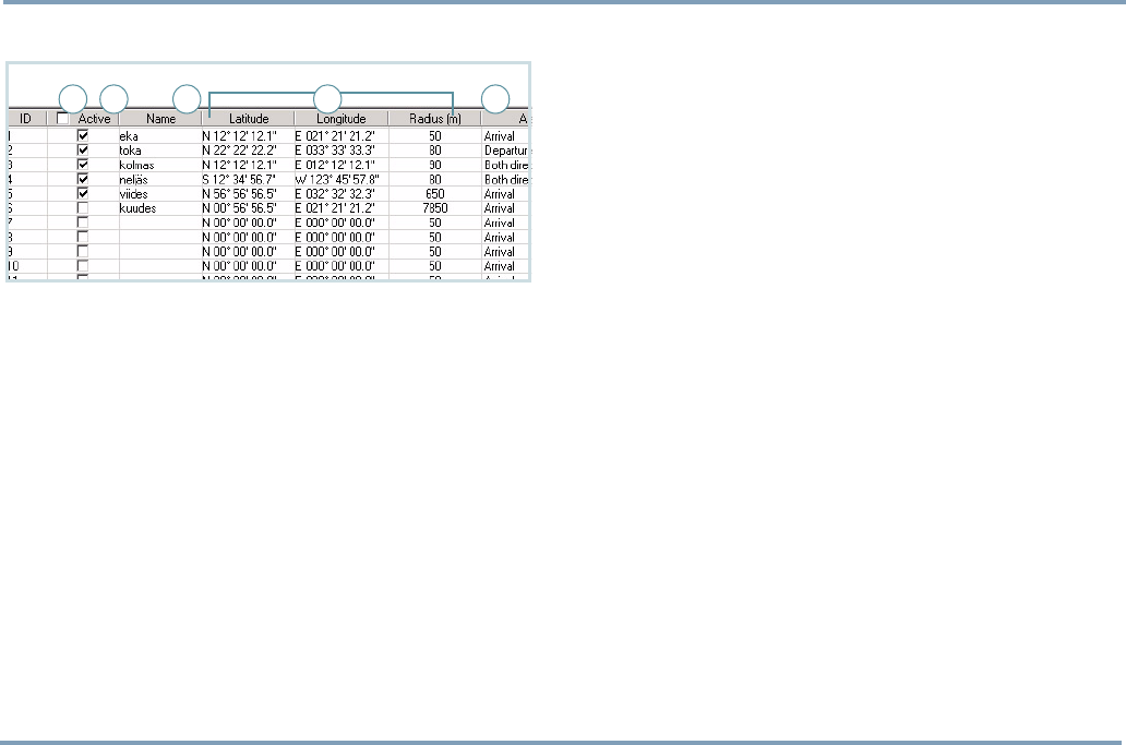
WAYPOINT TRACKING
Waypoint tracking is remotely controlled by the service cen-
ter. When the waypoint tracking is turned on, the alarm mes-
sage (incl. position information) will be sent to the service
center when the device is moving out or in to the pre-de-
fined area. The device can also be configured to send the po-
sition information to the service center whenever crossing
the borderline - despite of the moving direction.
NOTE: When entering into the pre-defined area, the alarm
will be sent when crossing radius. When entering out of the
pre-defined area, the alarm will be sent when crossing radi-
us plus perimeter of 100 meters.
•Name (1): You may key in the desired name for a waypoint
. You can define up to 30 separate, circular areas: The
areas are separated from each other by an ID number and
a name.
•Center point coordinates (2): The waypoint area is defined
by keying in Latitude and Longitude and a Radius of an
area in meters. The radius should be rounded to tens,
otherwise the software does the rounding. E.g. by enter-
ing 67, the actual radius will be rounded to 70 meters. 50
meters is the minimum value.
•Alarm (3): After activating a waypoint, you can select an
alarm option for this waypoint. You have three choices:
Alarm will be turned on when arriving to a waypoint,
departing from a waypoint, or whenever crossing the bor-
derline (both directions). Each waypoint can have alarm
option of its own.
•Activation of a waypoint (4): To activate a waypoint, check
the Active box (on the same row), to deactivate the way-
point, leave the check box blank.
NOTE: The waypoint tracking does not contain automatic
switch off or duration options. The feature must be sepa-
rately deactivated when it is no longer needed.
Resetting the coordinates
To reset the coordinate values, click the latitude and longi-
tude data fields (the ones, you want to reset).
Marking all waypoints for activation/
deactivation at once
Click the Active box on the top row (5).
Note that activation/deactivation will actually take place
only after you have transferred the information to the de-
vice.
1 2 345

ENCRYPTING MESSAGES 47
PART A: CONFIGURING SETTINGS FOR THE TRACKBOX
ENCRYPTING MESSAGES
SMS and MPTP messages can be protected from outsiders by
encrypting message contents. Encryption is an additional
feature. The feature is activated by an activation key sup-
plied to you by the manufacturer.
The whole procedure:
First activate the feature, next generate the keys, then select
the encryption options and finally save everything in the de-
vice.
NOTE: The device must be connected to the Benefon Con-
figurator software all the time during the procedure.
Activating encryption
To activate the feature, do as follows:
1. Connect the device with the software.
2. Open Save activation key from the Mobile menu.
3. Key in the activation key and click Save in mobile.
Generating keys
You need two different keys for encryption.
•Message encryption key: The "long key" is needed for
encrypting message contents.
•Distribution key: The distribution key is needed for
encrypting the new message encryption key (while it is
sent over the air). I.e. the distribution key secures the
new message encryption key during OTA transfer.
NOTE: If you generate the new message encryption key and
transfer it locally via the data cable, the distribution key is
not needed.
To generate the keys, do as follows:
1. Open Encrypting>Encrypting keys from the Edit menu.
2. Check the boxes and click Generate.
3. When generating the keys, the new keys will be created
into the files. Select the destination directory, name the
file and click Save. Name the other key file and click
Save once again.
4. Click Close.

PART A: CONFIGURING SETTINGS FOR THE TRACKBOX
48 CODE SETTINGS
Selecting encryption options
1. Open Encrypting>Encrypting keys from the Edit menu.
2. Select the desired options by checking the correspond-
ing boxes. See below:
Encrypting based on message type
- SMS and MPTP messages are NOT encrypted.
- Only MPTP messages are encrypted.
- Only SMS messages are encrypted.
- Both SMS and MPTP messages are encrypted.
Encrypting based on destination
- Messages to service center and authorized numbers are
NOT encrypted.
- Messages to service center are encrypted.
- Messages to authorized numbers are encrypted.
- Messages to service center and authorized numbers are
encrypted.
3. Check the boxes in the Save key in mobile phone.
4. Finally save all the options and the keys by clicking the
Save in mobile phone box on the bottom left. Browse the
directory, find the key file and click Open (do it twice to
save both keys).
CODE SETTINGS
Automatic PIN entry
The PIN code can be pre-programmed to the device
EEPROM. It cannot be read by any means from the device. In
startup the PIN code is entered automatically by the device
software.
The PIN code can be changed in the Benefon Configurator
by choosing Change PIN code from the Mobile menu. Key in
the new code and confirm it.
The option is available only when the Trackbox is connected
to the software.
Security code
The security code secures telematic settings. If the setting is
enabled, the code is requested each time when powering up
the system (software in connection with the device).
The security code settings are located in the Mobile menu.
- To enable the code, check the box. To disable the
code, leave the check box blank.
- To change the code, first click the corresponding box.
Key in the old code, key in the new code and confirm it.

INCOMING CALLS AND MESSAGES 49
PART B: OPERATING THE TRACKBOX
PART B: OPERATING THE
TRACKBOX
INCOMING CALLS AND MESSAGES
The device can receive calls, messages and requests. With
such messages you will make the device to activate func-
tions, update settings, send positions or logged data and so
on.
For incoming calls and messages
•a valid SIM card must be inserted and
•the device must be turned on.
Incoming calls
It is possible to listen in the Trackbox and its surroundings.
The device answers an incoming call automatically after cer-
tain number of rings,
The Auto answer setting must be turned on (the box must be
checked), otherwise an incoming call is dropped at once.
For more information, see AUTOMATIC ANSWER ON PAGE 18.
The Audio setting should be set to Internal, when using the
device´s own built-in microphone. For more information,
see AUDIO ON PAGE 19.
Incoming short messages
An incoming short message is echoed to the system connec-
tor, so that an external device can check it. Reading, writing,
sending and receiving normal short messages via the Track-
box is possible only in case the Trackbox is connected to
an external device, such as a computer. For more informa-
tion, see SHORT MESSAGES ON PAGE 13.
No messages are ever stored on SIM card. Even the MPTP
messages are cleared once they are processed.
Incoming MPTP messages
An incoming short message is processed only if it is a known
MPTP message.
If the Authorization setting is enabled, only messages from
authorized numbers are processed, others are discarded at
once. For more information, see AUTHORIZATION ON PAGE 27.
Authorized numbers include service center and emergency
center numbers and all the numbers stored in the list of au-
thorized numbers. For more information, see AUTHORIZED
NUMBERS ON PAGE 29.
In most cases, incoming MPTP messages are either remote
configuration/activation messages or various types of posi-
tion request messages.

PART B: OPERATING THE TRACKBOX
50 INCOMING CALLS AND MESSAGES
REMOTE CONFIGURATION MESSAGE
The device may receive an MPTP message for the remote
configuration. Remote configuration messages contain new
or updated settings for e.g. emergency numbers, authorized
numbers, AGPS-parameters, activity timer and GPS operat-
ing mode.
For more information on remote configuration, see the sep-
arate MPTP document.
AT commands
The device may receive an AT command via the configura-
tion port. The port is located inside the device, in the lower
part of the accessory module. For more information, see THE
CONFIGURATION PORT ON PAGE 9.
AT commands are used when configuring settings with the
Benefon Configurator, or some similar application. The AT
commands can be used for carrying out similar things that
are done via MPTP messages.
For more information on handling AT commands, see the
separate document on AT commands, located at the Web
site www.benefon.com.

OUTGOING CALLS AND MESSAGES 51
PART B: OPERATING THE TRACKBOX
OUTGOING CALLS AND MESSAGES
Depending on configuration, the device may send some
MPTP messages to the service center or authorized num-
bers. Such messages can be, e.g. power notifications or cal-
culated positions.
Resending MPTP messages
The device has MPTP message storage: If sending of an
MPTP message fails, e.g. in case there is no service at the mo-
ment, the device will send the message later, assuming the
MPTP protocol message storage has space left to deposit the
message. The storage capacity is 100 messages.
After the device is in service again, these messages are auto-
matically sent forward.
Power notifications
BATTERY STATUS MESSAGES
The device can be configured to inform the service center of
various incidents on its battery status. This configuration
can be done via the Benefon Configurator, or by sending a
specific MPTP message to the device.
When the device detects that e.g. the battery is low, or the
temperature is too cold or warm for using the battery, the
device will inform the service center by sending an MPTP
message to the service center.
The message will be sent only in case the event takes place
for the first time after powering on or being disconnected
from the charger.
For more information, see NOTIFY SERVICE CENTER OF BAT-
TERY STATUS ON PAGE 30, and the separate MPTP document.
CHARGER CONNECTION MESSAGES
The device can be configured to inform the service center of
changes in charger connection. When the device detects
that it is being connected to or disconnected from the charg-
er, the device will inform the service center by sending an
MPTP message to the service center.
For more information, see the separate MPTP document.

PART B: OPERATING THE TRACKBOX
52 OUTGOING CALLS AND MESSAGES
Emergency cycle (I/O model only)
EMERGENCY MESSAGES AND CALLS
In order to send emergency messages, the device must have
I/O functionality and a separate emergency switch. The
emergency switch can also be some kind of light/movement/
pressure indicator. Additionally the device must be config-
ured correctly. For more information on emergency set-
tings, see EMERGENCY SETTINGS ON PAGE 31.
As the emergency cycle takes place, the device is turned on
automatically (if it is currently off).
The emergency message contains both GPS coordinates and
GSM network measurement report.
The emergency message (including the latest position infor-
mation available) is put through via the emergency input pin
and I/O cable.
If an external audio (a combination of a microphone and
speaker) is connected, a voice call to both ways is possible.
Otherwise voice call means opening one-way audio: from
the device to the emergency center number. In this case
emergency center number can listen in the device and its
surroundings.
EMERGENCY CYCLE CHECK LIST
Necessary settings
1. The device must be the I/O model, which includes the
I/O functionality.
2. SIM card must be inserted in the device.
3. Emergency pin wire must be connected. For more in-
formation, see the Trackbox Installation Guide.
4. All required settings must be configured and trans-
ferred in the device in advance. Such settings are listed
below.
- Configuring settings can be done either by using the
Benefon Configurator and transferring the settings to
the device locally, via the data cable, OR by using the
MPTP messages and transferring the settings remotely
as an OTA (Over the Air) message.
5. Emergency center numbers must be set in the device.
For more information, see EMERGENCY CENTER NUMBERS
ON PAGE 32.
6. The emergency pin must be enabled. For more infor-
mation, see ACTIVATING EMERGENCY PIN ON PAGE 33.
7. Normal status for the emergency pin must be defined.
A change in the status works as a trigger for an emergen-
cy cycle to start. For more information, see SETTING
EVENT STATE ON PAGE 33.

OUTGOING CALLS AND MESSAGES 53
PART B: OPERATING THE TRACKBOX
Voluntary settings
1. Emergency message confirmation can be set, if the
control system supports it. For more information, see
EMERGENCY CONFIRMATION ON PAGE 32.
- If the emergency confirmation is activated, the device
waits for an acknowledgement message. If it is not get-
ting it in the pre-defined time, the device continues
sending the emergency message until it is acknowl-
edged. If the emergency center contains several emer-
gency numbers, the device will after unsuccessful
messaging send the message to the next number on the
list.
2. Emergency call connection waiting time can be set.
For more information, see EMERGENCY CALL CONNECTION
WAITING TIME ON PAGE 32.
3. Emergency call cycle mode can be set. It depends on
configuration whether the device first sends all the mes-
sages and then starts to make calls, or sends messages
and makes calls in pairs. For more information, see
EMERGENCY CALL CYCLE MODE ON PAGE 32.
4. Response time (a delay for starting an emergency cycle)
can be set. For more information, see DEFINING NOTIFICA-
TION DELAY ON PAGE 33.
Circumstances which may affect on
emergency cycle
1. Power supply
- Even when the device has continuous, fixed power sup-
ply, it is possible that the power source might run
down or be disconnected for a period of time because
of weather conditions or other circumstances (e.g. mis-
chief). For such situations, ensure that there is adquate-
ly charge left in the battery. Battery should never be
out-of-charge.
2. Message transmission errors
- Deliveries of all messages, including MPTP messages,
are fully handled by and in the responsibility of the
GSM network operator and services can vary substan-
tially.
3. Shadow areas
- If the device is permanently installed in a location
where frequently occurs poor satellite coverage or
weak network signal, external GPS and/or GSM anten-
nas must be installed with the device. Shadow areas
may also occur momentarily, while moving from place
to place, especially in tunnels, valleys, or under heavy
tree cover.

PART B: OPERATING THE TRACKBOX
54 OUTGOING CALLS AND MESSAGES
THE EMERGENCY CYCLE WHEN SENDING
SHORT MESSAGES AND MAKING CALLS
1. An emergency cycle can be initiated by pressing the sep-
arate emergency switch. The emergency switch can also
be replaced by some kind of an indicator. The emergen-
cy cycle starts as the status of the emergency pin chang-
es.
2. The device sends the latest position information along
with the message. If current position coordinates are
unavailable, previous coordinates will be sent instead.
3. The device calls the emergency center numbers, starting
from the top of the list.
4. A voice call in progress.
Making assistance call
1. An assistance call starts as the status of the digital input
pin9 changes.
2. The device sends the latest position information along
with the message. If current position coordinates are un-
available, previeous coordinates will be sent instead.
3. The device makes assistance call according to configura-
tion: It makes the information call and/or sends the mes-
sage including last known coordinates.
NOTE: The device must be the I/O model, and the digital in-
put pin9 must be connected and wired, and configured for
assistance call usage.
For more information, see I/O SETTINGS ON PAGE 31 and sepa-
rate Installation Guide.

OUTGOING CALLS AND MESSAGES 55
PART B: OPERATING THE TRACKBOX
Sending status messages
Status messages are related to digital and analoque input
pins. A status message is sent, when the event state of a pin
changes. The status message includes text, additional text
and last known coordinates.
A status message is sent to corresponding, separately config-
ured status message number or the service center number.
CHECK LIST FOR STATUS MESSAGES
Necessary settings
1. The device must be the I/O model, which includes the
I/O functionality. Only the I/O model contains pin con-
nectors. There can be several different status messages
(one for each input pin).
2. Wires for input pins must be connected. For more in-
formation, see the Installation Guide.
3. Status messages must be created and configured. A
status message includes the corresponding pin number,
message text, additional text and the phone number (i.e.
the destination number). For more information, see STA-
TUS MESSAGES FOR DIGITAL INPUT PINS ON PAGE 37 and STA-
TUS MESSAGES FOR ANALOGUE INPUT PINS ON PAGE 40.
4. The needed pin connectors must be activated. For
more information, see ACTIVATING DIGITAL INPUT PIN ON
PAGE 36 (for digital input pins), and ACTIVATING ANA-
LOGUE INPUT PIN ON PAGE 39 (for analogue pins).
5. Event status for the needed pins must be defined. A
change in the event state works as a trigger for sending
a status message. For more information, see SETTING
EVENT STATE ON PAGE 36 (for digital input pins) and SET-
TING EVENT STATE ON PAGE 39 (for analogue pins).
6. Desired events for the needed pins must be defined. In
order to send status messages, Event data field must be
set to Send status report or Send and write. For more in-
formation, see SELECTING EVENT ON PAGE 36 (for digital
pins) and SELECTING EVENT ON PAGE 39 (for analogue
pins).
7. Reference values for analogue pins must be defined.
For more information, see SETTING REFERENCE VALUES ON
PAGE 40.
Voluntary settings
1. Notification delay can be set. For more information,
see DEFINING NOTIFICATION DELAY ON PAGE 36 (for digital
input pins) and DEFINING NOTIFICATION DELAY ON PAGE 40
(for analogue pins).
2. Event log can be set. When the Event log is set to All
events are logged or Marked events are logged, the infor-
mation of the event will also be logged. For more infor-
mation, see EVENT LOG SETTINGS ON PAGE 43.

PART B: OPERATING THE TRACKBOX
56 OUTGOING CALLS AND MESSAGES
Circumstances which may
affect on sending status messages
1. Power supply
- Even when the device includes a continuous, fixed
power supply, it is possible the power source might run
down or be disconnected for a period of time because
of weather conditions or other circumstances (e.g.mis-
chief). For such situations, ensure that there is adquate-
ly charge left in the battery. Battery should never be
out-of-charge.
2. Message transmission errors
- Deliveries of all messages, including MPTP messages,
are fully handled by and in the responsibility of the
GSM network operator and services can vary substan-
tially.
3. Shadow areas
- If the device is permanently installed in a location
where frequently occurs poor satellite coverage or
weak network signal, external GPS and/or GSM anten-
nas must be installed with the device. Shadow areas
may also occur momentarily, while moving from place
to place, especially in tunnels or valleys.
Positioning features
ACTIVITY TIMER PROCEDURE
1. The activity timer is activated as soon as the time set in
the Start time data field matches with the current time.
2. The device will be turned on. This automatic power-up
does not cause the LEDs to be lit.
3. According to configuration the position is calculated and
sent to the service center. For more information on con-
figuring activity timer, see ACTIVITY TIMER ON PAGE 16.
4. The device will then remain in idle mode for the pre-de-
fined time after which it will be turned off.
However, the power-down can be postponed by sending a
Location Request (?LOC) message to the device. Postpon-
ing might be necessary for e.g. completing all ongoing
events before the power will be turned off.
All tracking messages, including ?LOC messages, override
the Interval time set in the Activity timer. For more informa-
tion on ?LOC messages, see below.

OUTGOING CALLS AND MESSAGES 57
PART B: OPERATING THE TRACKBOX
RESPONDING LOCATION REQUEST(?LOC)
The device may receive several different types of messages
requesting location. Such messages can be, e.g. Location re-
quest (?LOC) messages or Location history request (?HIS).
For more information on how the device responds these
kind of messages, see DEFAULT BEHAVIOUR FOR LOCATION RE-
QUEST ON PAGE 25.
For more information on how to create location request
messages, see the separate MPTP document.
RESPONDING LOCATION HISTORY REQUEST
(?HIS)
The device responds the location history request by sending
several old positions with desired intervals to the requesting
number (service center number). If requested, the whole
trace of the device can be unravelled afterwards.
Otherwise responding procedure works the same way as it
does in a single location request (see above).
NETWORK POSITIONING SUPPORT
The device can be requested to send its current GSM net-
work parameters at any time. Requesting number could be,
e.g. service center. The message that the device sends as a
response is called the Network Measurement Report (NMR).
The device will send network parameters to the requesting
number automatically in two cases:
•Authorization is enabled and the requesting number is
authorized.
•Authorization is entirely disabled.
Emergency center and service center numbers are always
authorized.
If the authorization is enabled and the position request
comes from an unauthorized number, the device will dis-
card the request.
If the service center number is defined and authorization is
disabled, the response is always sent to the service center
number.
The Network Measurement Report contains rough data and
the position needs to be separately calculated by taking into
account surrounding base stations and distances in between
them. Calculation of the position needs a separate server,
available from Benefon Partners. The device cannot calcu-
late the position based on network parameters by itself.

PART B: OPERATING THE TRACKBOX
58 OUTGOING CALLS AND MESSAGES
Trace log
The device stores position data in its memory automatically.
Stored data contains position information and time stamp.
The maximum storage capacity is 1000 positions. Once the
log is full, the device stacks the information by dropping off
irrelevant positions. When positions cannot be dropped any
more without losing important information, there are two
ways to proceed:
•Log overwrite: In case the log is not transferred at all, the
device will automatically replace the oldest positions with
the new ones.
•Log transfer: The log can be transferred from the device
locally, by using the Benefon Configurator and data cable.
DOWNLOADING TRACE LOG
When the device returns home, connect it to the Benefon
Configurator by data cable. The log is loaded from the de-
vice to the software the same way as other settings. For more
information, see LOADING SETTINGS FROM THE TRACKBOX TO
THE SOFTWARE ON PAGE 10.
When the Benefon Configurator loads the log from the de-
vice, the trace log file appears automatically in the display in
readable text format. The Trace log icon is shown under the
My Benefon node on the left, and by clicking the icon the ac-
tual trace log file will be shown in the Document window on
the right.
Saving log file
To save the trace log in the Benefon Configurator, choose
Save or Save as.. from the File menu. The trace log file will
be saved in readable text format (.log).
Deleting log file
To delete the trace log in the Benefon Configurator, choose
Delete trace log from the Mobile menu.
NOTE: If you delete trace log from My Benefon node, the log
is lost once and for all. So, make sure to store the log some-
where in case you need to recall the log information after-
wards.
PROCESSING TRACE LOG BY USING SOME
OTHER APPLICATION
Trace log files cannot be edited in Benefon Configurator. In
order to modify or print the log file, do as follows:
1. First save the log in Benefon Configurator. The log file
identifier will become .log.
2. Open Windows Excel or Notepad. Make sure, the Files
of type shows All files.
3. Open the log file in the chosen application.
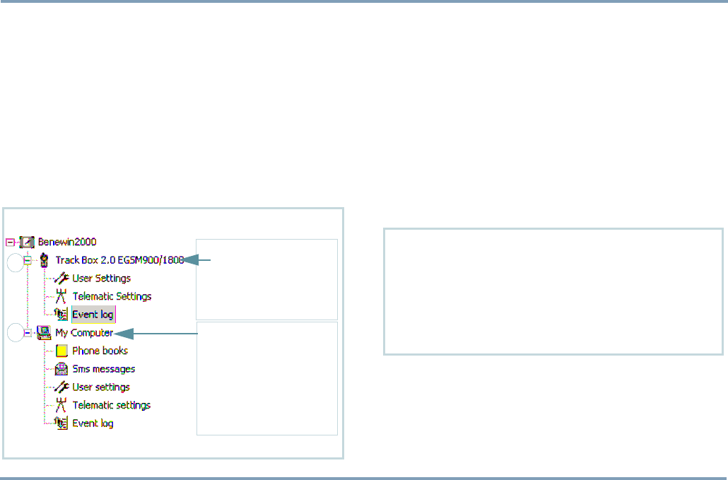
OUTGOING CALLS AND MESSAGES 59
PART B: OPERATING THE TRACKBOX
Recalling event log (I/O model only)
The device can be configured to store positions and I/O
events registered by pins. Once the log is full, the device
maintains already collected log information but does NOT
store any new events unless the log is cleared or sent to the
service center. For more information on logging events and
positions, and transferring the log, see LOG SETTINGS ON
PAGE 43.
You have two ways to recall logged information: Local trans-
fer and remote transfer.
LOCAL TRANSFER
When the device returns home, it is connected to the Bene-
fon Configurator by BWTrackbox cable. The log is loaded
from the device to the software the same way as other set-
tings. For more information, see LOADING SETTINGS FROM THE
TRACKBOX TO THE SOFTWARE ON PAGE 10.
When the Benefon Configurator loads the log directly from
the device, the event log file appears automatically in the
display in readable text format. The Event log icon is shown
under the mobile phone node (1) on the left, and by click-
ing the icon normally the actual event log file will be shown
on the right.
MOBILE PHONE NODE
Shows data recently downlo-
aded from a device, e.g.
Telematic settings, User
settings and locally transfer-
red Event log.
COMPUTER NODE
•Shows existing Benefon
Configurator files just sto-
red in the computer.
•Shows new (blank) Bene-
fon Configurator files.
•Shows remotely transferred
event log.
1
2
IF THE DEVICE DOES NOT LOAD Event log ICON IN THE DISPLAY,
MAKE SURE THAT
•The device contains logged information.
•The Load event log box is checked in Benefon Configurator. You
can find it as follows: Open the Edit menu, select Settings and
go to the Mobile phone startup tasks to check the box.
To load the log from the device later on in the same session, select
Load event log from the Mobile menu.

PART B: OPERATING THE TRACKBOX
60 OUTGOING CALLS AND MESSAGES
REMOTE TRANSFER
The device sends the log to the service center remotely, as a
CSD call, using Z-modem protocol. The CSD data call number
and service center number must be configured in the Trackbox
in advance. For more information, see SERVICE CENTER NUM-
BER ON PAGE 27 and CSD NUMBER ON PAGE 45.
The computer must contain a modem application which sup-
ports Z-modem protocol (e.g. Windows Hyperterminal).
NOTE: Check the modem settings. Serial port must be correct,
and transfer speed must be set according to receiving phone.
E.g. when using the Benefon mobile phone as the receiving
phone, transfer speed must be set to 19200 Bits/Second.
During the transfer, the receiving mobile phone must be con-
nected to the computer by a data cable/BWTrackbox cable.
NOTE: Automatic answer setting of the receiving mobile
phone is for voice calls, not data calls and thus it must be
turned off.
In order to make the modem answer automatically incoming
data calls, key in the command ats0=1 on the screen of the
modem and press Enter on the keyboard. The command is as-
sociated with the receiving mobile phone. (the automatic an-
swer for data calls can be turned off by keying in the command
ats0=0)
The incoming log file will be found in your computer. Default
destination directory depends on modem settings and can be
changed. In most cases the log file can be located at the root
directory of the modem application. The binary-coded log file
identifier is .DAT. Here is a sample case by using Hypertermi-
nal, see below:
STEP1: CONFIGURING MODEM APPLICATION FOR DATA RECEPTION
1. Connect the receiving mobile phone to the computer by data cab-
le and open the Windows Hyperterminal modem application.
2. Open New connection (from the File menu if the dialog box is not
displayed). Name the connection -> Ok. Select port for the con-
nection (e.g. COM1) -> Ok.
3. Set transfer speed to 19200 Bits/Second ->Ok.
4. Open Receive file.. from the Transfer menu. Click Browse and
find the desired destination directory ->Ok. Select Z-modem for
Receiving protocol -> Receive.
When the modem configuration is done, you may save the file by
clicking Save as... from the File menu.
Close the connection by clicking Disconnect from the Call menu.
From now on, whenever you need this connection, you can use the
profile just created by selecting Open... from the File menu.
STEP2: RECEIVING REMOTELY SENT LOG FILE
Connect the receiving phone to the computer by data cable/BWTrack-
box cable and open the Windows Hyperterminal modem application.
To ensure the connection between mobile phone and the modem, you
may key in ATI on the screen and press Enter -> the modem will iden-
tify receiving mobile phone.
Key in ats0=1 and press Enter -> the mobile phone will answer auto-
matically to incoming CSD calls.
When the mobile phone starts alerting, the modem will display RING.
When the mobile phone answers, the data transfer dialog box appears
on the screen. When the transfer is finished, the dialog box disap-
pears and the connection can be switched off.
If you do not use the automatic answer, do as follows (when the phone
starts alerting): Press the Hook-up key on the phone keypad OR key
in ATA on the screen and press Enter.

OUTGOING CALLS AND MESSAGES 61
PART B: OPERATING THE TRACKBOX
OPENING REMOTELY SENT LOG FILE
IN BENEFON CONFIGURATOR
Start the Benefon Configurator and open the event log file
as follows:
1. Highlight the Event log icon shown on the left side of the
screen, under My computer node (2).
2. Choose Open from the File menu (or, click the mouse´s
right button and highlight Open).
3. Click the Files of type setting and highlight All Benefon
Configurator files.
4. Browse the directories and files until the destination di-
rectory and file is found. The file identifier is binary.DAT
Click Open.
Event log file is originally in binary-coded format. As the file
is opened in the Benefon Configurator, the software gener-
ates the file and displays it as a table in a readable text for-
mat.
PROCESSING EVENT LOG IN BENEFON
CONFIGURATOR
Saving the log file
To save the event log in Benefon Configurator, choose Save
or Save as.. from the File menu. The event log file will be
saved in readable text format (.log). Also the binary coded
log file (.DAT), which was transferred as a CSD call, can be
stored in readable text format (.log).
Deleting the log file
To delete the event log in Benefon Configurator, choose De-
lete event log from Mobile menu. NOTE: If you delete event
log from mobile phone node, the log is lost once and for all.
So, make sure the log is stored in some place else in case
you need the log information afterwards.
PROCESSING EVENT LOG BY USING SOME
OTHER APPLICATION
Event log files cannot be edited in Benefon Configurator. In
order to modify or print the log file, do as follows:
1. First save the log in Benefon Configurator. The log file
identifier will become .log.
2. Open Windows Excel or Notepad. Make sure, the Files
of type shows All files.
3. Open the log file in the application.

PART C: POWER MANAGEMENT
62 POWER SUPPLY
PART C: POWER MANAGEMENT
POWER SUPPLY
The device contains built-in charger plus one of the follow-
ing batteries:
•Li-Ion Backup battery 650 mAh (BBL78S)
•Standard Li-Ion batteries:
- 650 mAh (BBL77S)
- 900 mAh (BBL77N)
- 1200 mAh (BBL77P)
- 1700 mAh (BBL77G)
In I/O model it is also possible to use Power adapter instead
of batteries. Power adapter uses external power input di-
rectly.
The battery type may vary depending on the market area and
sales package. In unclear cases, check the battery compati-
bility with the dealer.
CHARGING
The battery must be fully charged before taken into use. The
battery will reach its full capacity only after two or three
charging times.
The device controls the charging status, the battery temper-
ature and power supply during the charging operation. You
can find out the status of the battery e.g. by monitoring the
indicating LEDs.
The ideal temperature range for charging is +10°...+30°C. If
charging the battery above or below these temperatures the
life of a battery may be shortened. Also, the battery may not
reach full capacity.
Never charge a standard battery at temperatures below 0°C.
When using a backup battery, charging below 0°C is prevent-
ed automatically.
Charging time depends on what kind of a charger and bat-
tery you have in use.
Also note that humidity, temperature, age of the used bat-
tery and currently used devices (e.g. the GPS) affect the
time spent on charging.
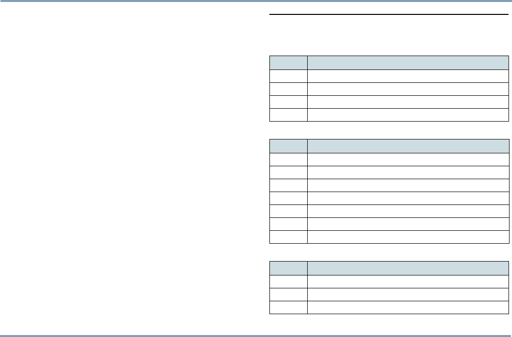
BATTERY CARE AND MAINTENANCE 63
PART D: ACCESSORIES
BATTERY CARE AND MAINTENANCE
The continuous operating time is less when using an old
battery than when using a new battery.
When storing batteries for a long time, it is recommended
that the batteries are kept cool and fully charged in a dry
place.
Proper care and storage guarantee best possible battery ca-
pacity and maximum battery life.
DISPOSAL OF A BATTERY
Li-Ion batteries do not contain heavy metals which can dam-
age the environment. Li-Ion batteries should be disposed of
according to the country-specific regulations.
PART D: ACCESSORIES
BATTERIES, POWER SOURCES
EXTERNAL ANTENNAS
BWTRACKBOX CABLES, DEMO TOOL
CODE PART
YO2301 Standard Li-Ion battery, 650 mAh
YO2413 Li-Ion Power battery, 1700 mAh
YO2611 Li-Ion Backup battery, 650 mAh
YO2610 Power adapter
CODE PART
ZE2408 External GPS antenna, Radiall
ZE3231 External GSM antenna, Drill mount (fixed)
ZE3230 External GSM antenna, Glass mount
ZE3232 External GSM antenna, Cottage mount
YA2414 Combi antenna,GPS+GSM (coming up)
YC2608 GPS antenna adapter (required for external GPS antenna)
YC2607 GSM antenna adapter (required for external GSM antenna)
CODE PART
ZE2306 Data cable APC70
ZE2406 Data/NMEA cable
ZE2602 Benefon Trackbox Demo tool

PART E: IMPORTANT SAFETY INFORMATION
64 DEVICE CARE AND MAINTENANCE
PART E: IMPORTANT SAFETY
INFORMATION
DEVICE CARE AND MAINTENANCE
NOTE: The instructions below apply to the device, its acces-
sories, batteries in use as well as batteries taken out of use.
•Dust and dirt may damage the moving parts of the device.
Do not use or keep the device in dusty or dirty surround-
ings.
•Do not open the battery or solid parts of the device by
yourself or pierce holes in them.
•Rough handling may break the circuitry inside the device.
Do not drop, knock, twist or shake the device or its bat-
tery.
•Keep the device dry. Liquids contain minerals which could
corrode electronic circuits. If the device gets wet, turn it
off and wipe the device and the battery immediately. Put
the device into an upright position and let it dry. It is rec-
ommended that a dealer or service personnel check that
the device functions properly.
•Do not wet the device or battery or immerse either one in
water. Even though the device is tough, it is not catego-
rized to be used in damp conditions. Protection against
dust and water can be considerably improved by assem-
bling the device carefully, inserting the rubber seal to
tighten battery and using o-ring seals with screws. If the
device is frequently used in damp conditions, it is recom-
mended to provide it with separate housing, which does
not prevent antenna signals.
•External accessories, connections and attachements must
be separately protected against dust and water. In case
there are holes pierced in the device for some cable inlets,
e.g. for the BWTrackbox cable, and such cables are not in
place, the holes must be separately covered by some
waterproof material.
•Protect the device from heat. High temperatures may
shorten the life of the electronical devices, melt or warp
plastics and damage batteries. Do not warm up the device
or battery or use it near fire.
•Do not short-circuit the battery. Exposing the metal strips
of the battery to a close contact with a metallic object,
such as a coin, a clip or a set of keys can cause accidental
short-circuiting and damage the battery.
•Charge and recharge the battery only with the charger
specified in the manual. Use the battery only for the pur-
pose it is intended.
•Clean the device with a soft cloth, dampened slightly with
mild soapy water. Do not clean the device with harsh
chemicals, solvents or other corrosive substances.
•Only allow service personnel authorised by the dealer to
assemble, connect and service the device.

SAFETY AND PRECAUTIONS 65
PART E: IMPORTANT SAFETY INFORMATION
SAFETY AND PRECAUTIONS
Telematics protocol
MPTP (Mobile Phone Telematic Protocol) allows, among
other things, tracking of the device over the SMS communi-
cation.
Automatically sent telematics messages are only allowed to
authorized numbers configured in the device. Such num-
bers can be, e.g. emergency and service center numbers.
Position of the device is retrieved by the GPS, or by the net-
work parameters - the latter is a network-dependent service.
The carrier for telematics messages is an SMS-message. De-
liveries of all messages is fully handled by and in the respon-
sibility of the GSM network operator and services can vary
substantially.
The charge of a protocol message is determined on the con-
tract by the service provider.
GPS
The Global Positioning System (GPS) is operated by the gov-
ernment of the United States, which is solely responsible for
its accuracy and maintenance. The system is subject to
changes that could affect the accuracy and performance of
all GPS equipment.
Emergency calls
The device is an aid and should never be relied upon as an
only emergency device. Its functionality is dependent on
GSM network and GPS satellites which may not be available
all the time.
To make emergency calls, the device must be turned on,
charged and located in an area with adequate GSM network
signal strength. A valid SIM card must be inserted in the de-
vice and the device must be configured to make emergency
calls.
Connection is not quaranteed in all conditions. Rough ter-
rain or large buildings may limit the operation of the device.
Never completely rely upon the device for essential commu-
nications.

PART E: IMPORTANT SAFETY INFORMATION
66 SAFETY AND PRECAUTIONS
General safety notes
•Traf fi c: It is advisable to strictly adhere to all eventual
European and national legislation and also honour other
eventual safety recommendations when using the device
while driving a vehicle. When receiving a call in an awk-
ward driving situation, you must always put safety before
other priorities and courtesy. If you feel uncomfortable
about using a device while driving, you should not use it.
•Air bags: An air bag inflates with great force. Do not place
objects, including either installed or portable wireless
devices, in an area over the air bag or in the air bag
deployment area.
•External alert: The use of the alert device to operate a
vehicle´s lights or horn on public roads is not permitted.
•Children: Keep the device and its accessories away from
small children to avoid causing injury to themselves or
others. Damage to the device or its accessories is also thus
avoided.
•Power supply: The device is intended for use with the
power supplies specified in PART C: POWER MANAGEMENT ON
PAGE 62. Any other usage will invalidate any approval
given to this apparatus and may be dangerous.
•Loose batteries: Make sure, the batteries and spare bat-
teries are kept away from conductive materials, such as
coins, jewelry, keys, and other metal objects, because a
close contact of these materials and batteries can cause
short-circuit, injury, burns or some other damage. Be
especially careful when placing batteries inside your
pocket, purse, or other container with metal objects.
•Other accessories: Any other accessories used should
also be approved by the device manufacturer. Check the
compatibility of new power supply units and other acces-
sories at the dealer. Disconnect the power cord of any
accessory by grasping and pulling the plug, not the cord.
•Connections: All installations, connections and service
regarding the device, its power supply and accessories
should be approved by the device manufacturer. Use of
any unauthorized accessories, modifications or attach-
ments may be dangerous and voids the device warranty if
said accessories cause damage or a defect to the device.
Note that device´s own antenna must be disconnected
when attaching an external GSM antenna to the device.
The external GSM antenna adapter is a standard cable
containing two separate connectors: SMA for the Track-
box, and FME for the external antenna.
•Magnetic fields: The device contains small magnetic
components. Even though the magnetic fields of the com-
ponents are weak, they might damage magnetic cards,
such as bank and credit cards. We recommend that you
would keep the device away from magnetic cards.
•Storing positions: Position information is stored cor-
rectly in the device when the GPS is turned off (from the
GPS menu) or powered off (by pressing the topmost side
key). To prevent the memory from becoming corrupted,
never power off the device by removing the battery.

SAFETY AND PRECAUTIONS 67
PART E: IMPORTANT SAFETY INFORMATION
FCC Statement
The device is designed for and intended to be used in fixed
and mobile applications. Fixed means that the device is
physically secured at one location and cannot be easily
moved to another location. Mobile means that the device is
designed to be used in other than fixed locations.
A minimum separation distance of at least 20 cm (8 inches)
must be maintained between the antenna and persons for
this device to satisfy the RF Exposure requirements of the
FCC.
For fixed mount operation, the antenna co-location require-
ments of Section 1.1307 (b)(3) of the FCC rules must be sat-
isfied. For fixed mount operation, the maximum gain of the
antenna must not exceed 7 dBi. For mobile operation, the
maximum gain of the antenna must not exceed 3 dBi.
WARNING: Use of this device in portable operations is not
permitted.
Radio frequency (RF) energy
The device may cause TV or radio interference if used in
close proximity to receiving equipment. The FCC can re-
quire you to stop using the device if such interference can-
not be eliminated.
Vehicles using liquefied petroleum gas (such as propane or
butane) must comply with the National Fire Protection Stan-
dard (NFPA-58). For a copy of this standard, contact the Na-
tional Fire Protection Association, One Batterymarch Park,
Quincy, MA 02269, Attn: Publication Sales Division.
This equipment has been tested and found to comply with
the limits for a Class B digital device, pursuant to Part 15 of
the FCC Rules. These limits are designed to provide reason-
able protection against harmful interference in a residential
installation.
This equipment generates, uses and can radiate radio fre-
quency energy and, if not installed and used in accordance
with the instructions, may cause harmful interference to ra-
dio communications.
However, there is no guarantee that interference will not oc-
cur in a particular installation. If this equipment does cause
harmful interference to radio or television reception, which
can be determined by turning the equipment off and on, the
user is encouraged to try to correct the interference by one
or more of the following measures:
•Reorient or relocate the receiving antenna.
•Increase the separation between the equipment and
receiver.
•Connect the equipment into an outlet on a circuit differ-
ent from that to which the receiver is connected.
•Consult the dealer or an experienced radio/TV technician
for help.

PART E: IMPORTANT SAFETY INFORMATION
68 SAFETY AND PRECAUTIONS
Any changes or modifications to your phone not expressly
approved in this document could void your warranty for this
equipment and void your authority to operate this equip-
ment.
Potential RF energy interference areas
•Aircrafts: Turn the device off before boarding any aircraft
and do not use the device while in the air, also make
sure that an automatic timer function will not acti-
vate the device during flight. Besides being illegal, the
use of a device in an aircraft may endanger the operation
of the aircraft or disrupt the mobile network. Failure to
comply with this instruction may lead to suspension or
denial of mobile phone services, and possibly even legal
action.
•Hospitals: Turn the device off before entering hospitals
or other health care facilities where medical electronic
equipment may be in use. Such devices can be extremely
sensitive to radio frequency interference. Only use the
device with permission and under the instruction of hos-
pital staff.
•Medical devices: Remember that any personal medical
devices (such as hearing aids or pacemakers) may be
affected by RF energy if they are not adequately shielded.
Consult the manufacturer or vendor of the equipment to
determine the proper shielding.
•Posted facilities and country-specific regulations:
Power down the device in any facility where posted
notices so require. Also follow all the country-specific reg-
ulations applicable to where the device is used.
•Potentially explosive or flammable atmospheres: Turn
off the device at refuelling points, e.g. gas stations. Also
observe restrictions on the use of radio equipment in fuel
depots, chemical plants or where blasting operations are
in progress because remote control RF devices are often
used to set off explosives. Do not store or carry flammable
liquids, gases or explosive materials in the same compart-
ment as the device, its parts or accessories.
•Electronic systems in vehicles and other electronic
devices: Using the device may cause interference with
electronic systems of a vehicle, e.g. electronic anti-skid
braking systems, electronic cruise control systems, air
bags etc. or electronic devices in a vehicle, e.g. a car ste-
reo, tv set, an alarm system etc. if the equipment is not
adequately shielded.Consult the manufacturer or the vehi-
cle seller to determine the proper shielding.
•Computers: Remember that using the device close to a
computer may cause interference. When using the device
near such equipment keep a distance of about one meter.
•Body parts: When the device is in operation do not touch
the antenna with eyes, mouth or bare skin to guarantee
proper function.

SAFETY AND PRECAUTIONS 69
PART E: IMPORTANT SAFETY INFORMATION
Ancillary equipment
Benefon cannot be responsible in any way for any ancillary
equipment not provided by Benefon, which is attached to or
used in connection with Trackbox or for the operation of
Trackbox with any ancillary equipment and all such equip-
ment is expressively excluded from the warranty of Track-
box. Because each system which Trackbox may use is
unique, Benefon disclaims liability for range, coverage or
operation of the system as a whole under this warranty.

PART E: IMPORTANT SAFETY INFORMATION
70 BENEFON WARRANTY
BENEFON WARRANTY
A warranty certificate with the date of purchase is enclosed
in the delivery. Service operations are carried out for free at
Benefon during the warranty period.
BENEFON warrants its products to be free of defects in ma-
terial or workmanship when leaving the factory. If a defect
is found during the given warranty period, the customer
should without delay and latest within the given warranty
period return the product, together with the warranty certif-
icate and the purchase receipt, to the BENEFON dealer who
sold the product or, if this is not feasible, to any other au-
thorised BENEFON sales or service facility.
A defective product with valid BENEFON warranty will be
made good by having it repaired or replaced, as seen appro-
priate by BENEFON in each case. Repair or replacement of
the product does not extend the original warranty period.
The warranty does not cover defects caused by using the
product with peripheral equipment or accessories not sup-
plied or approved by BENEFON, or defects caused by repairs
or modifications carried out by parties not authorised by
BENEFON.
Neither does the warranty cover defects directly attributable
to abuse, misuse or accident of any kind nor changes in con-
sumable parts (e.g .batteries) attributable to normal wear
and tear.
The warranty is void if the manufacturing identity data at-
tached to the product have been altered, erased or rendered
unidentifiable.
BENEFON assumes strictly no responsibility for special, in-
cidental, punitive or consequential damages, or loss of use.
The warranty period of this BENEFON product expires..............
.......................................................................................................
BENEFON dealer who sold the product.........................................
.........................................................................................................
.........................................................................................................
IMEI code/serial number.................................................................
P.O. Box 84, FIN-24101 Salo, Finland,
Fax int. +358 2 733 2633
-----
--------------------------------------------------------------------------
-