Benq M25 M25 GSM Wireless Module User Manual Manual revised
Benq Corporation M25 GSM Wireless Module Manual revised
UserManual.wiki
>
Benq
>
M25 User Manual
Manual revised
Navigation menu
Upload a User Manual
Namespaces
Wiki Guide
HTML
PDF
Info
Views
User Manual
Discussion / Help
Navigation
![ !"#$"$% 2 DOCUMENT REVISION HISTORY ISSUE DATE AUTHOR COMMENTS [0.1] 2007/1/30 Kevin RY Cheng Creation](https://usermanual.wiki/Benq/M25/User-Guide-794837-Page-2.png)
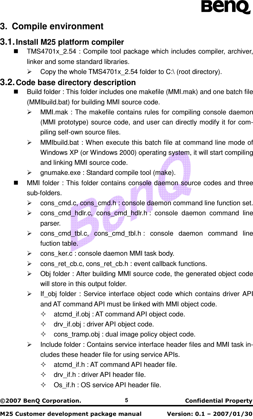
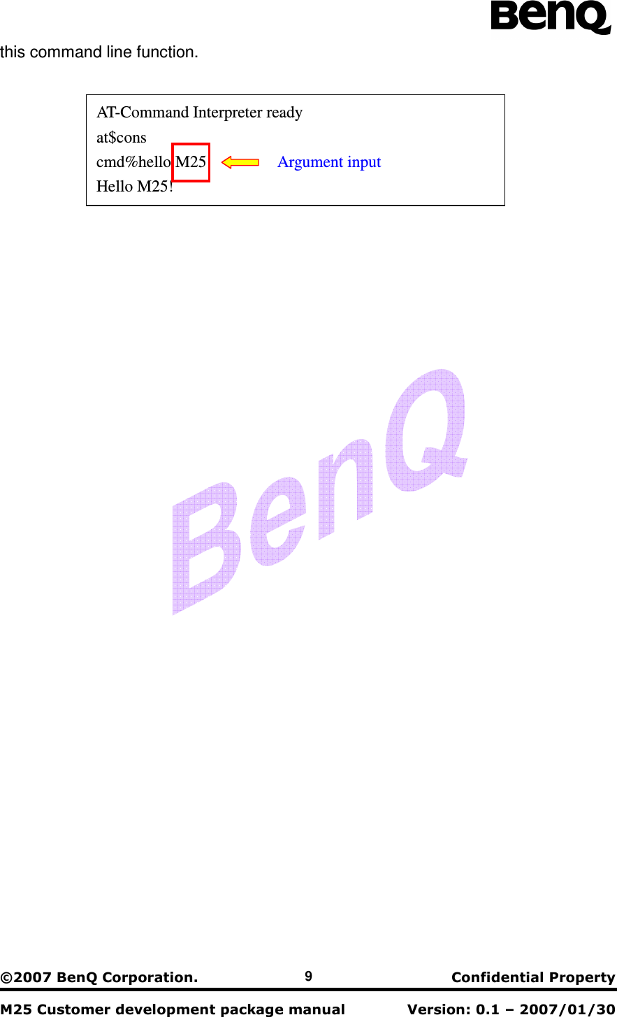
![ !"#$"$% 6 Out folder : This folder includes image files. M25[version_number].m0 : System core image file. MMI.m0 : Generated MMI image file. MMI.map : Generated MMI memory mapping file. Sys folder : This folder contains runtime support libraries and one command file (MMI.cmd) which contains memory mapping information for linking im-age file. rts16le_flash.lib, rts16le_int_ram.lib : runtime support libraries. mmi.cmd : memory mapping command file. Version folder : Version number text of system core image. 4. Download image In development phase, customers must download both M25 system core image file and MMI image file. BenQ provides USB based GUI download tool for customer to download image files. i. Download MMI image file. ii. Then, download system core image. iii. After rebooting the module device, module will start initialization proce-dures and communicating with network. The download tool manual contains detailed download tool configuration and oper-ating steps. 5. Command line interface of console daemon Console daemon provides command line interface for development phase de-bugging. After downloading image files and resetting module device, the default set-ting of UART port is used for sending external AT command. Connect EVB board with PC terminal via UART port and execute Windows hyper-terminal application. Hy-per-terminal application will show the follow message: This message shows that external AT command interface is ready. Input AT command string from hyper-terminal into UART port of module and this AT command string is directly sending to AT command interpreter which is component of ACI pro-AT-Command Interpreter ready _](https://usermanual.wiki/Benq/M25/User-Guide-794837-Page-6.png)
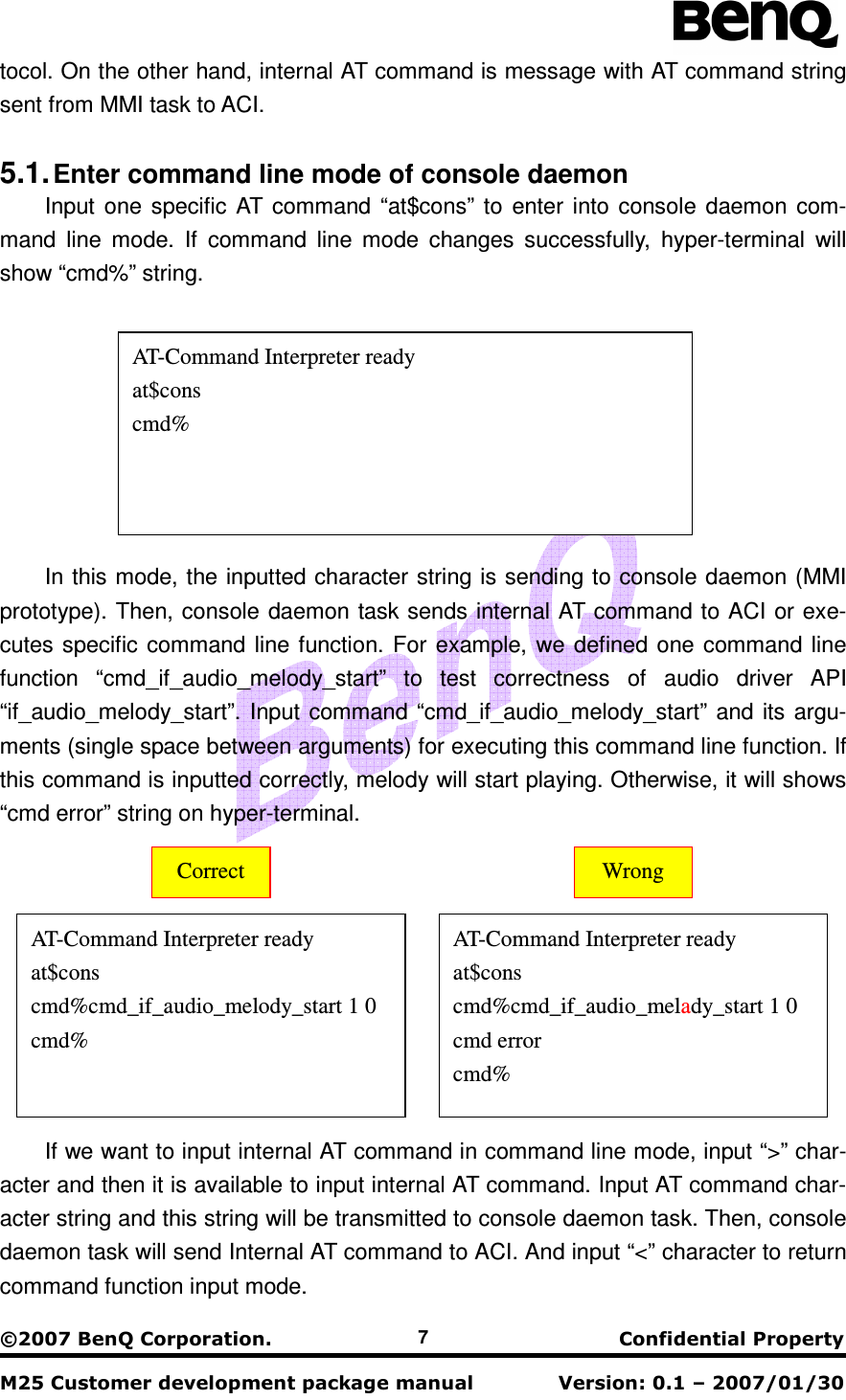
![ !"#$"$% 8 5.2. Add new command line function The command line interface is extendable for user adding or modifying command line functions. The adding function steps are: i. Add new command line function body into cons_cmd.c. ii. Add new data entry (contains function information) into command func-tion table(cons_cmd_tbl.c). After finishing these steps, we can type “hello” command to execute “cmd_hello” const tCOMMAND atCmdTbl[] = { Data entry #n { “hello”, Command (MyFunc)cmd_hello, Function name “command line example”, Description { “module”, (STRING_ARG | REQUIRED_ARG), Arguments and its NULL, 0 Terminal property (string) } }, NULL }; Ex: void cmd_hello ( unsigned int iArgNum Number of argument char * module) { c_printf(“\n\rHello %s!”, module); } AT-Command Interpreter ready at$cons cmd%> at Internal AT command ok < cmd% Command line function mode](https://usermanual.wiki/Benq/M25/User-Guide-794837-Page-8.png)