Benq M25 M25 GSM Wireless Module User Manual Manual revised
Benq Corporation M25 GSM Wireless Module Manual revised
Benq >
Manual revised

!"#$"$%
1
M25 GSM Wireless Module
Customer development package manual
Rev.0.1
2007/1/30
COPYRIGHT BENQ Corporation
This document contains proprietary technical information which is the property of BenQ Corporation
and is issued in strict confidential and shall not be disclosed to others parties in whole or in parts
without written permission of BenQ Corporation
The documents contain information on a product, which is under development and is issued for cus-
tomer evaluation purposes only.
BENQ may make changes to product specifications at any time, without notice.
BenQ Corporation.
Networking & Communications BG
18 JiHu Road, Nei-Hu, Taipei 114, Taiwan
Tel: +886-2-2799-8800
Fax: +886-2-2799-8332
http://www.benq.com
!"#$"$%
2
DOCUMENT REVISION HISTORY
ISSUE
DATE AUTHOR COMMENTS
[0.1] 2007/1/30
Kevin RY Cheng
Creation
!"#$"$%
3
1. M25 software architecture
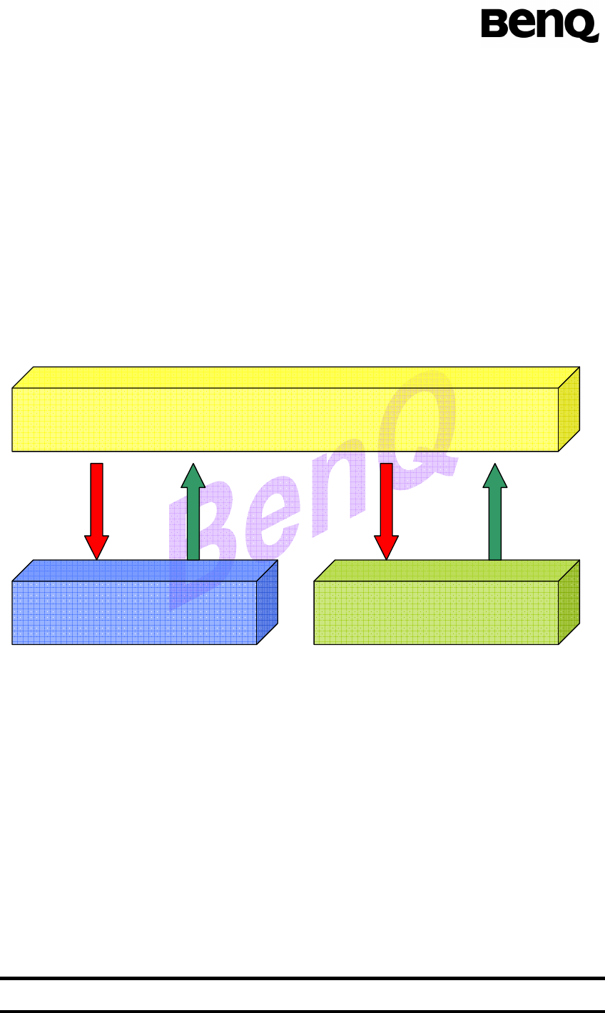
This Module platform provides dual channels for MMI task to control protocol
stack and hardware device respectively. These service interfaces are Internal AT
command interface and driver service interface, as shown in Figure 1.
MMI task sends message which carries string based AT command to protocol
stack. By this way, MMI task must register AT command call back function for han-
dling occurred event. Hence, MMI task controls communication procedure via this
“Internal AT command” directly without extra hardware device support. Moreover,
previous BenQ module platform uses AT command to control hardware device. This
platform provides simply and uniform specific driver API for operating hardware de-
vice.
Figure 1 Service interfaces for MMI task
1.1. Internal AT command API
MMI task sends AT command string via internal AT command interface, and re-
ceives response message from registered callback function. The follow APIs are used
to handle those procedures.
If_at_init() : This function is used to register callback function.
If_at_cmd() : This function is used to send internal AT command.
MMI
AT command
Interface
Driver Service
Interface
Internal
AT command
Response
Callback
Driver API
Event
Callback

!"#$"$%
4
1.2. Driver service interface
BenQ provide complete specific driver API, which are:
LCD driver API
128*64 Black & White SPI control LCD.
Keypad driver API
Audio driver API
Three sound types: key-beep, tone, melody.
Two audio paths: hand-held, hand-free.
GPIO driver API
5 GPIO pins for customers.
Real Time Clock API
Flash File System driver API
Power Management API
Communication Channel API
Communicate with external device via UART or USB port.
1.3. Dual image architecture
This platform provides one advanced code building policy which is “dual image”
architecture. Convention is compiling and link whole source files into one image file.
Hence, customer must maintain lots of library files and cost much time to download
the huge image file.
Dual image architecture is divide source code into two parts. The core proce-
dures which contain system, drivers and protocol are linked into one image file, and
MMI procedures of customer are built into another image file independently. By this
method, code management is more convenient. After module product leaving the
factory, the core image file is already downloaded into module and users only need to
download the MMI image. Hence, it costs users less time for proceeding download
procedure.
2. Console daemon
BenQ provides an MMI task prototype with development phase debug environ-
ment, which called “console daemon”. This software component simulates the MMI
task to communicate with module system core. Customers will know how to imple-
ment MMI task in this platform easily and conveniently via this task prototype. The
debug environment with command line interface is used to examine the correctness
of procedure and export the debug message via the serial port.

!"#$"$%
5
3. Compile environment
3.1. Install M25 platform compiler
TMS4701x_2.54 : Compile tool package which includes compiler, archiver,
linker and some standard libraries.
Copy the whole TMS4701x_2.54 folder to C:\ (root directory).
3.2. Code base directory description
Build folder : This folder includes one makefile (MMI.mak) and one batch file
(MMIbuild.bat) for building MMI source code.
MMI.mak : The makefile contains rules for compiling console daemon
(MMI prototype) source code, and user can directly modify it for com-
piling self-own source files.
MMIbuild.bat : When execute this batch file at command line mode of
Windows XP (or Windows 2000) operating system, it will start compiling
and linking MMI source code.
gnumake.exe : Standard compile tool (make).
MMI folder : This folder contains console daemon source codes and three
sub-folders.
cons_cmd.c, cons_cmd.h : console daemon command line function set.
cons_cmd_hdlr.c, cons_cmd_hdlr.h : console daemon command line
parser.
cons_cmd_tbl.c, cons_cmd_tbl.h : console daemon command line
fuction table.
cons_ker.c : console daemon MMI task body.
cons_ret_cb.c, cons_ret_cb.h : event callback functions.
Obj folder : After building MMI source code, the generated object code
will store in this output folder.
If_obj folder : Service interface object code which contains driver API
and AT command API must be linked with MMI object code.
atcmd_if.obj : AT command API object code.
drv_if.obj : driver API object code.
cons_tramp.obj : dual image policy object code.
Include folder : Contains service interface header files and MMI task in-
cludes these header file for using service APIs.
atcmd_if.h : AT command API header file.
drv_if.h : driver API header file.
Os_if.h : OS service API header file.

!"#$"$%
6
Out folder : This folder includes image files.
M25[version_number].m0 : System core image file.
MMI.m0 : Generated MMI image file.
MMI.map : Generated MMI memory mapping file.
Sys folder : This folder contains runtime support libraries and one command
file (MMI.cmd) which contains memory mapping information for linking im-
age file.
rts16le_flash.lib, rts16le_int_ram.lib : runtime support libraries.
mmi.cmd : memory mapping command file.
Version folder : Version number text of system core image.
4. Download image
In development phase, customers must download both M25 system core image
file and MMI image file. BenQ provides USB based GUI download tool for customer to
download image files.
i. Download MMI image file.
ii. Then, download system core image.
iii. After rebooting the module device, module will start initialization proce-
dures and communicating with network.
The download tool manual contains detailed download tool configuration and oper-
ating steps.
5. Command line interface of console daemon
Console daemon provides command line interface for development phase de-
bugging. After downloading image files and resetting module device, the default set-
ting of UART port is used for sending external AT command. Connect EVB board with
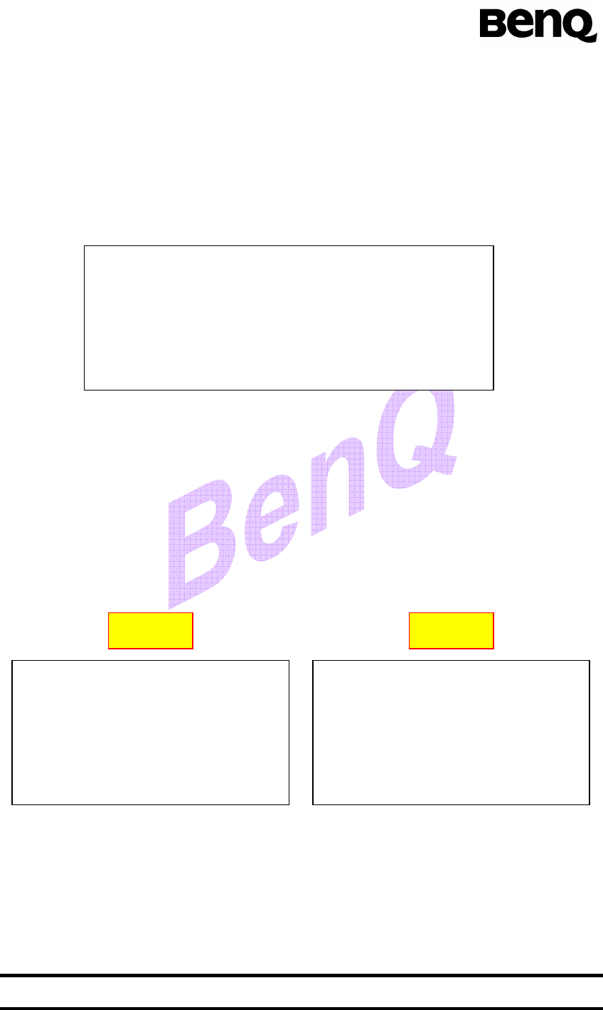
PC terminal via UART port and execute Windows hyper-terminal application. Hy-
per-terminal application will show the follow message:
This message shows that external AT command interface is ready. Input AT
command string from hyper-terminal into UART port of module and this AT command
string is directly sending to AT command interpreter which is component of ACI pro-
AT-Command Interpreter ready
_
!"#$"$%
7
tocol. On the other hand, internal AT command is message with AT command string
sent from MMI task to ACI.
5.1. Enter command line mode of console daemon
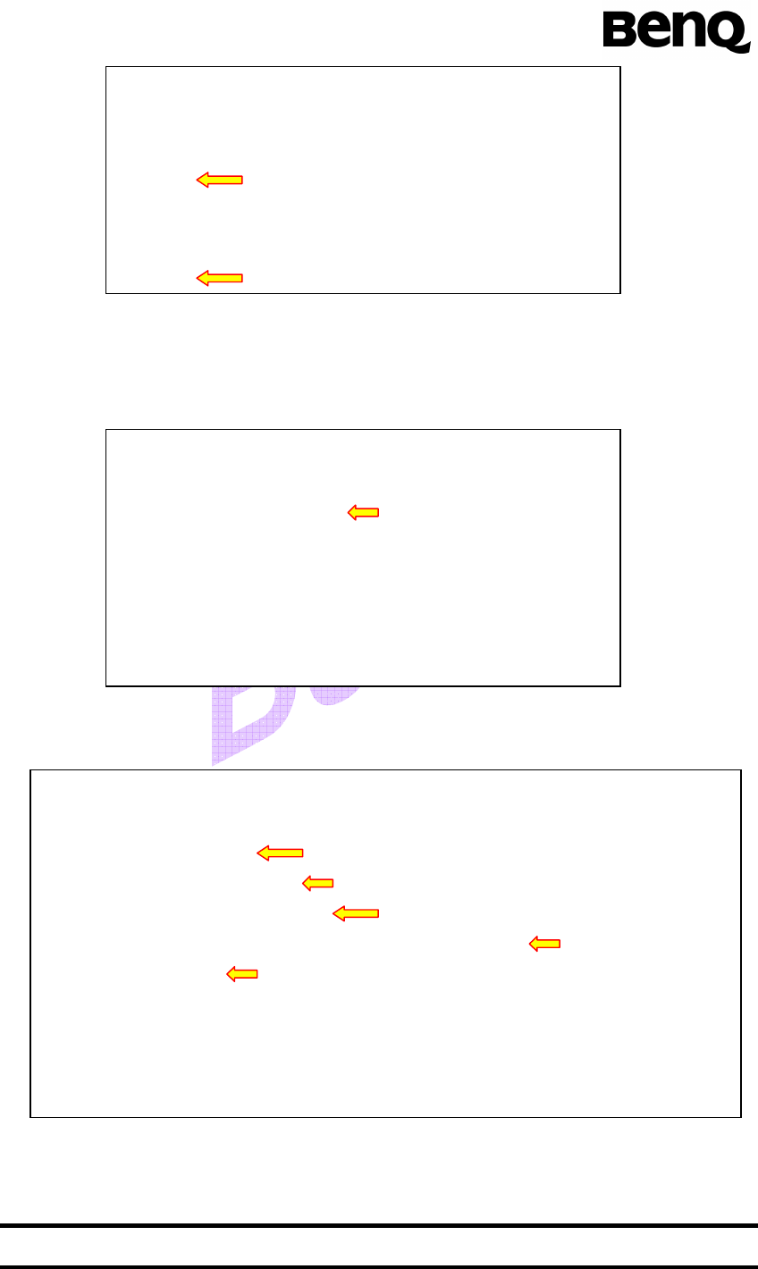
Input one specific AT command “at$cons” to enter into console daemon com-
mand line mode. If command line mode changes successfully, hyper-terminal will
show “cmd%” string.
In this mode, the inputted character string is sending to console daemon (MMI
prototype). Then, console daemon task sends internal AT command to ACI or exe-
cutes specific command line function. For example, we defined one command line
function “cmd_if_audio_melody_start” to test correctness of audio driver API
“if_audio_melody_start”. Input command “cmd_if_audio_melody_start” and its argu-
ments (single space between arguments) for executing this command line function. If
this command is inputted correctly, melody will start playing. Otherwise, it will shows
“cmd error” string on hyper-terminal.
If we want to input internal AT command in command line mode, input “>” char-
acter and then it is available to input internal AT command. Input AT command char-
acter string and this string will be transmitted to console daemon task. Then, console
daemon task will send Internal AT command to ACI. And input “<” character to return
command function input mode.
AT-Command Interpreter ready
at$cons
cmd%cmd_if_audio_melody_start 1 0
cmd%
AT-Command Interpreter ready
at$cons
cmd%cmd_if_audio_melady_start 1 0
cmd error
cmd%
Correct Wrong
AT-Command Interpreter ready
at$cons
cmd%
!"#$"$%
8
5.2. Add new command line function
The command line interface is extendable for user adding or modifying command
line functions. The adding function steps are:
i. Add new command line function body into cons_cmd.c.
ii. Add new data entry (contains function information) into command func-
tion table(cons_cmd_tbl.c).
After finishing these steps, we can type “hello” command to execute “cmd_hello”
const tCOMMAND atCmdTbl[] =
{ Data entry #n
{ “hello”, Command
(MyFunc)cmd_hello, Function name
“command line example”, Description
{ “module”, (STRING_ARG | REQUIRED_ARG), Arguments and its
NULL, 0 Terminal property (string)
}
},
NULL
};
Ex:
void cmd_hello
( unsigned int iArgNum Number of argument
char * module)
{
c_printf(“\n\rHello %s!”, module);
}
AT-Command Interpreter ready
at$cons
cmd%>
at Internal AT command
ok
<
cmd% Command line function mode
!"#$"$%
9
this command line function.
AT-Command Interpreter ready
at$cons
cmd%hello M25 Argument input
Hello M25!
©2006 BenQ Corp. Confidential Property
M25 DATASHEET Version: 0.1 – 2006/10/10
28
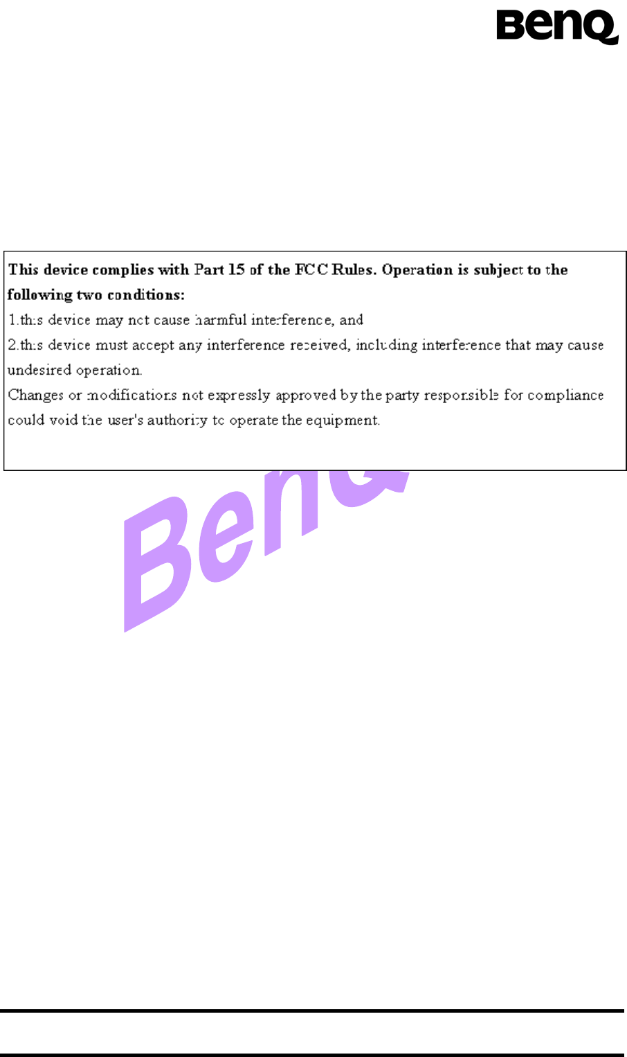
5.1 Compliance with FCC Rules and Regulations
The FCC Equipment Authorization Certification for the M25 reference application described
in Section 5.1 is listed under the
FCC identifier JVPM25
IC: 6175A-M25
granted to BenQ Corporate.
Note:
1. The maximum antenna gain allowed for use with this device is 0 dBi.
2. When the module is installed in the host device, the FCC ID label must be visible through a win-
dow on the final device or it must be visible when an access panel, door or cover is easily re-
moved. If not, a second label must be placed on the outside of the final device that contains the
following text: “Contains FCC ID: JVPM25”.