Berthold Technologies FCC01X12 Concentration, Dry, Mass, Water measuring system User Manual 39531BA2 04CETECOM HW
Berthold Technologies Concentration, Dry, Mass, Water measuring system 39531BA2 04CETECOM HW
UserManual.wiki
>
Berthold Technologies
>
FCC01X12 User Manual
User Manual
Navigation menu
Upload a User Manual
Namespaces
Wiki Guide
HTML
PDF
Info
Views
User Manual
Discussion / Help
Navigation
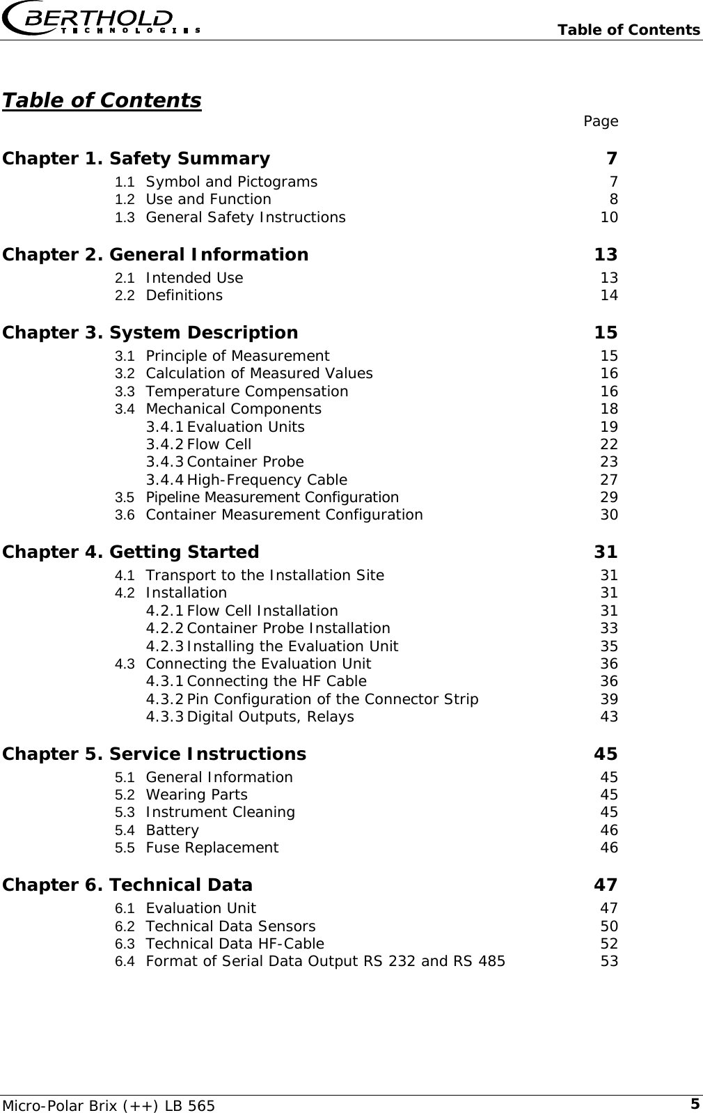
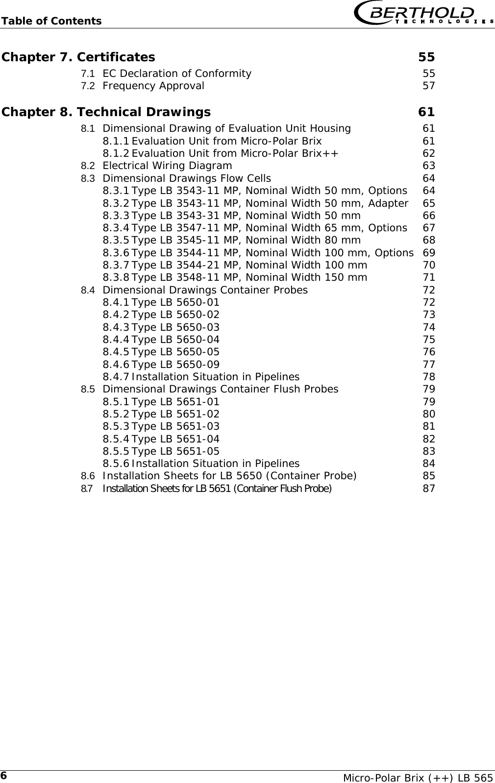

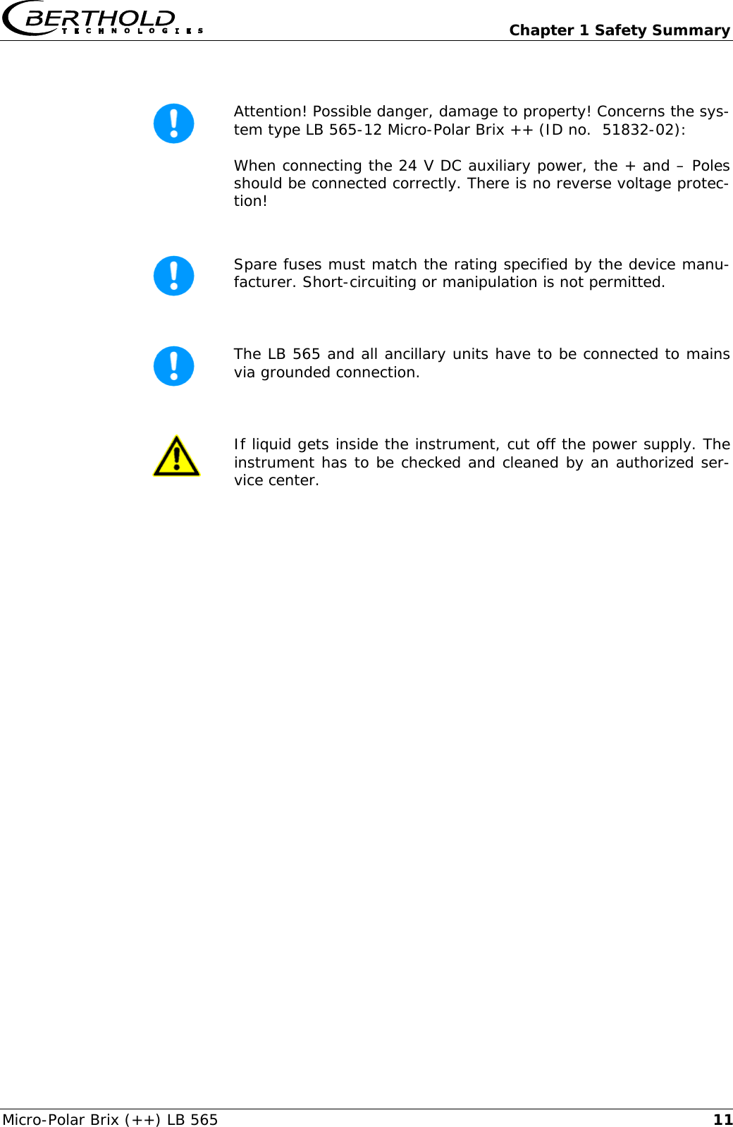
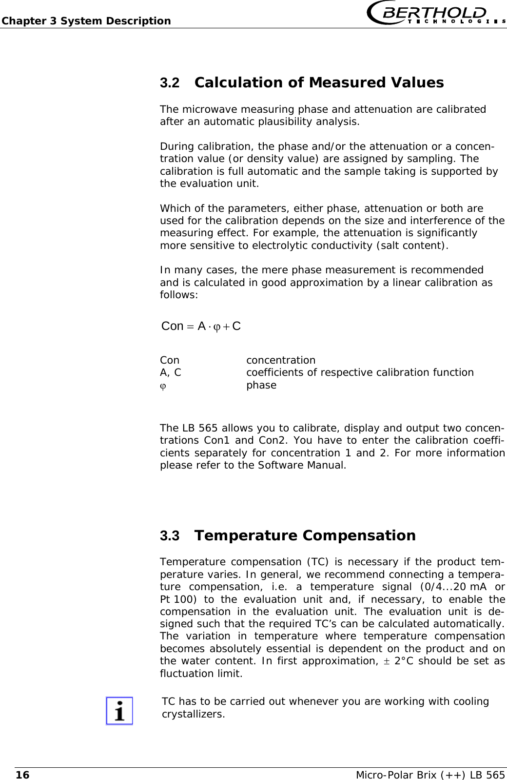
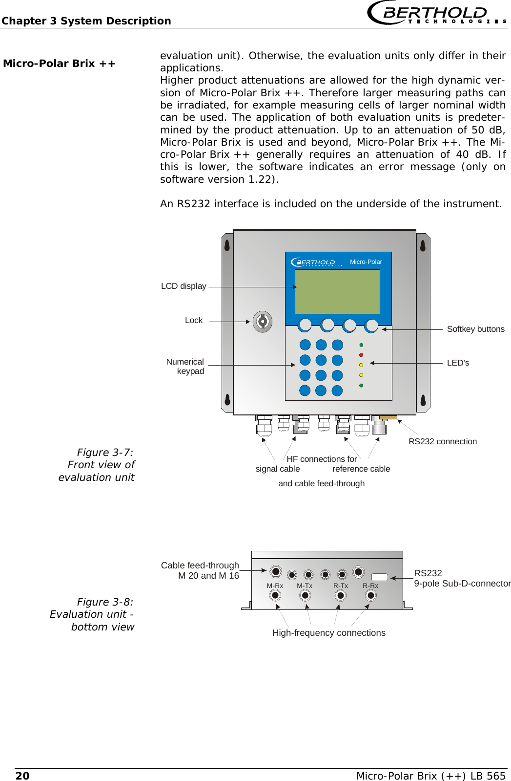
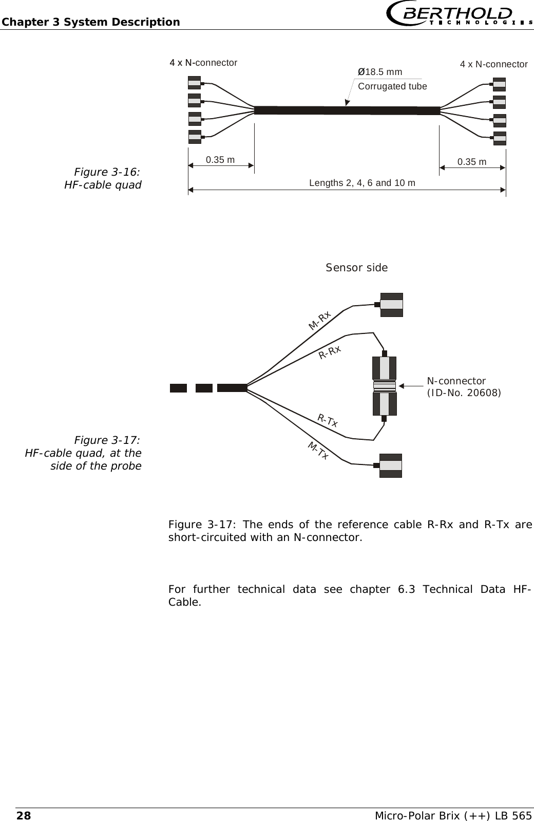
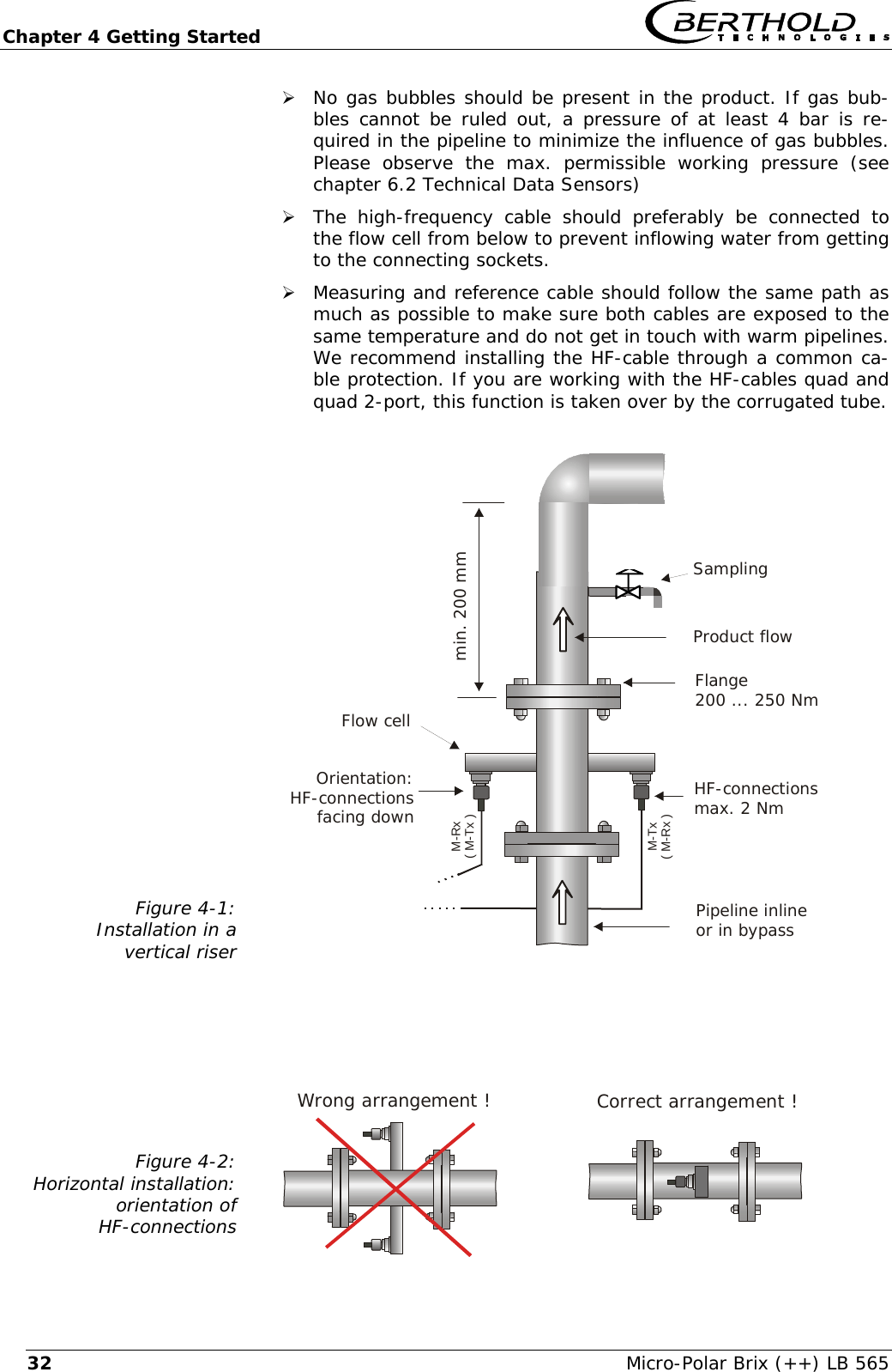
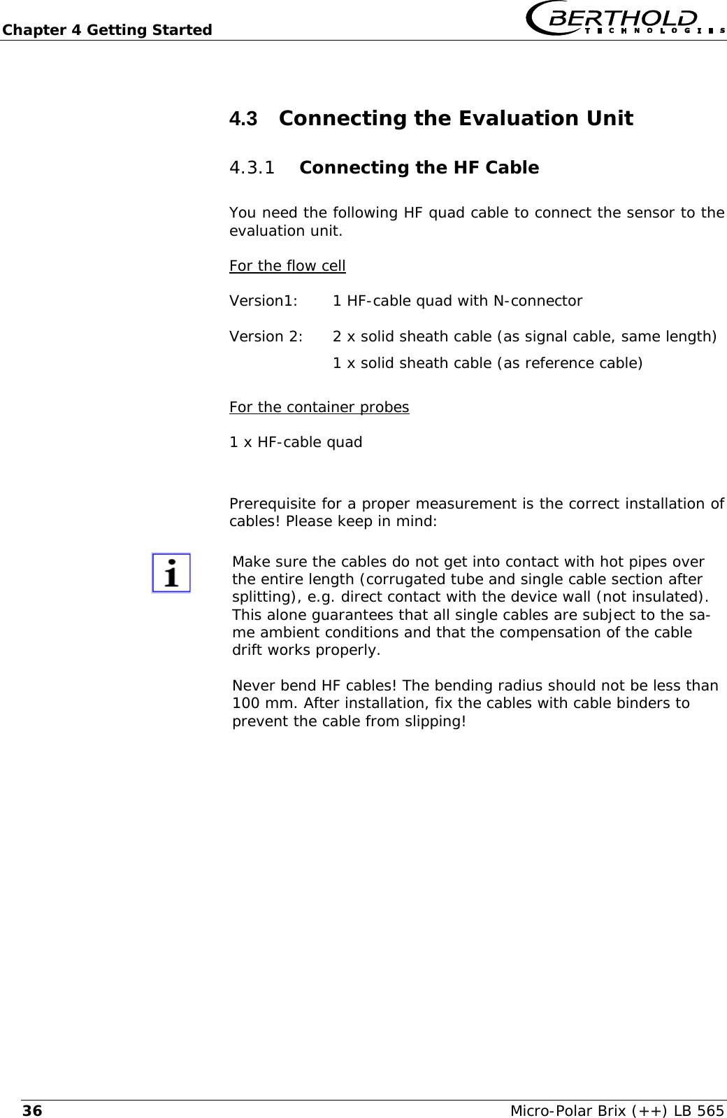
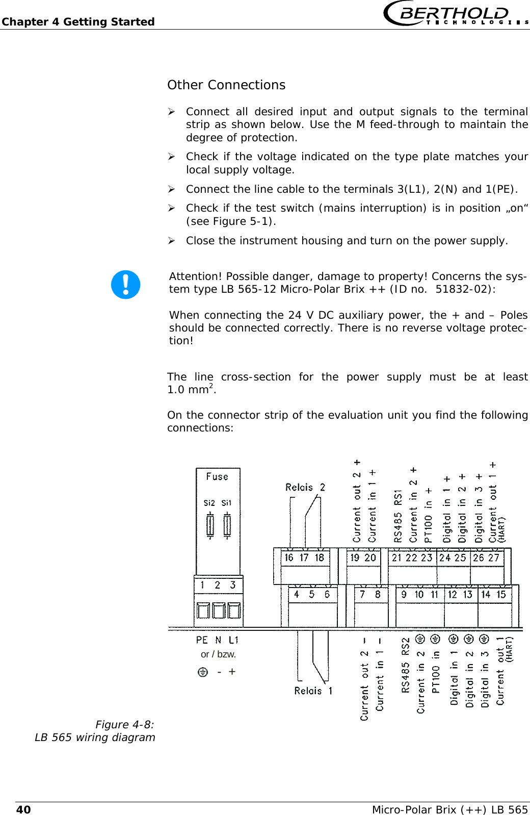
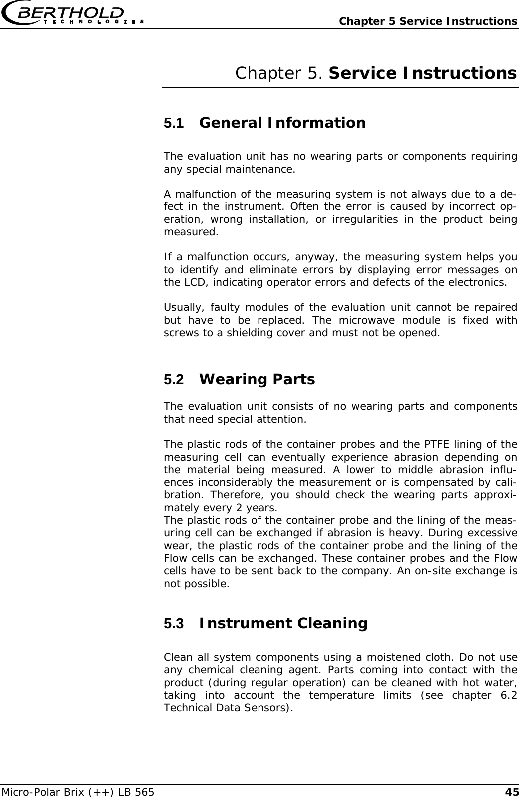
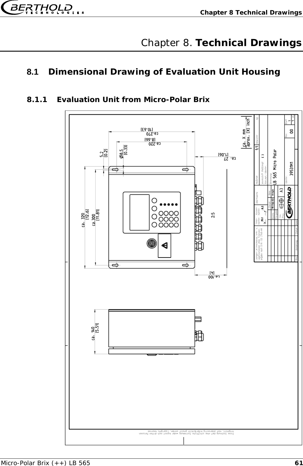
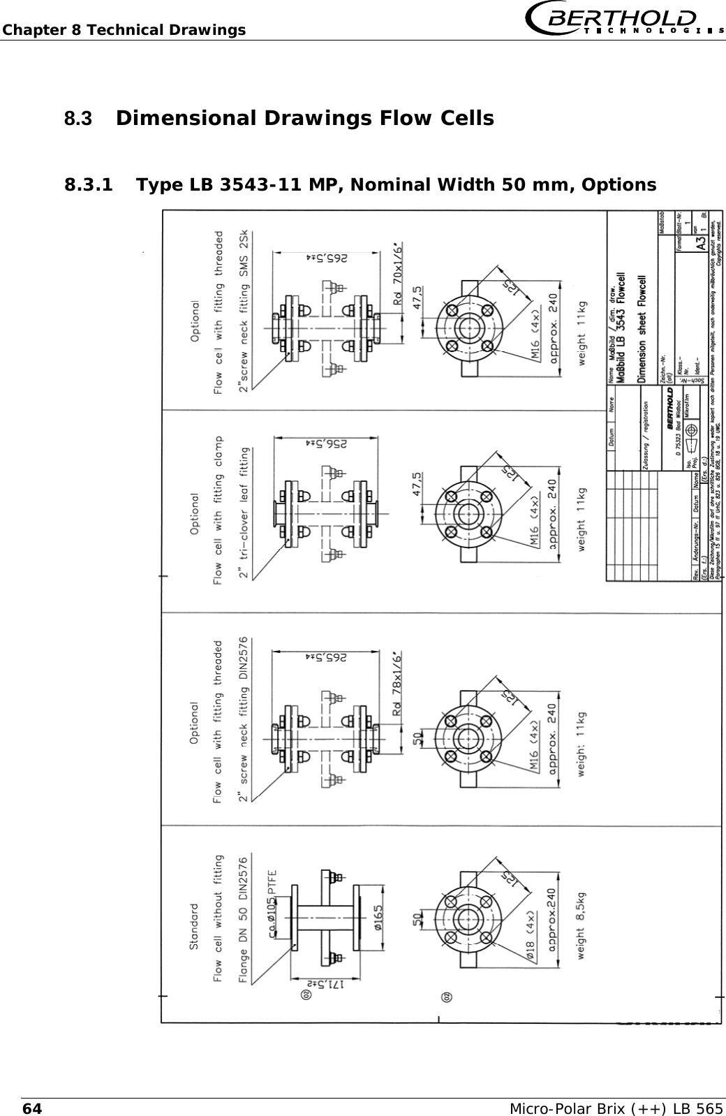
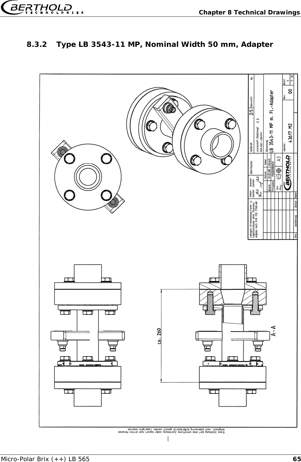
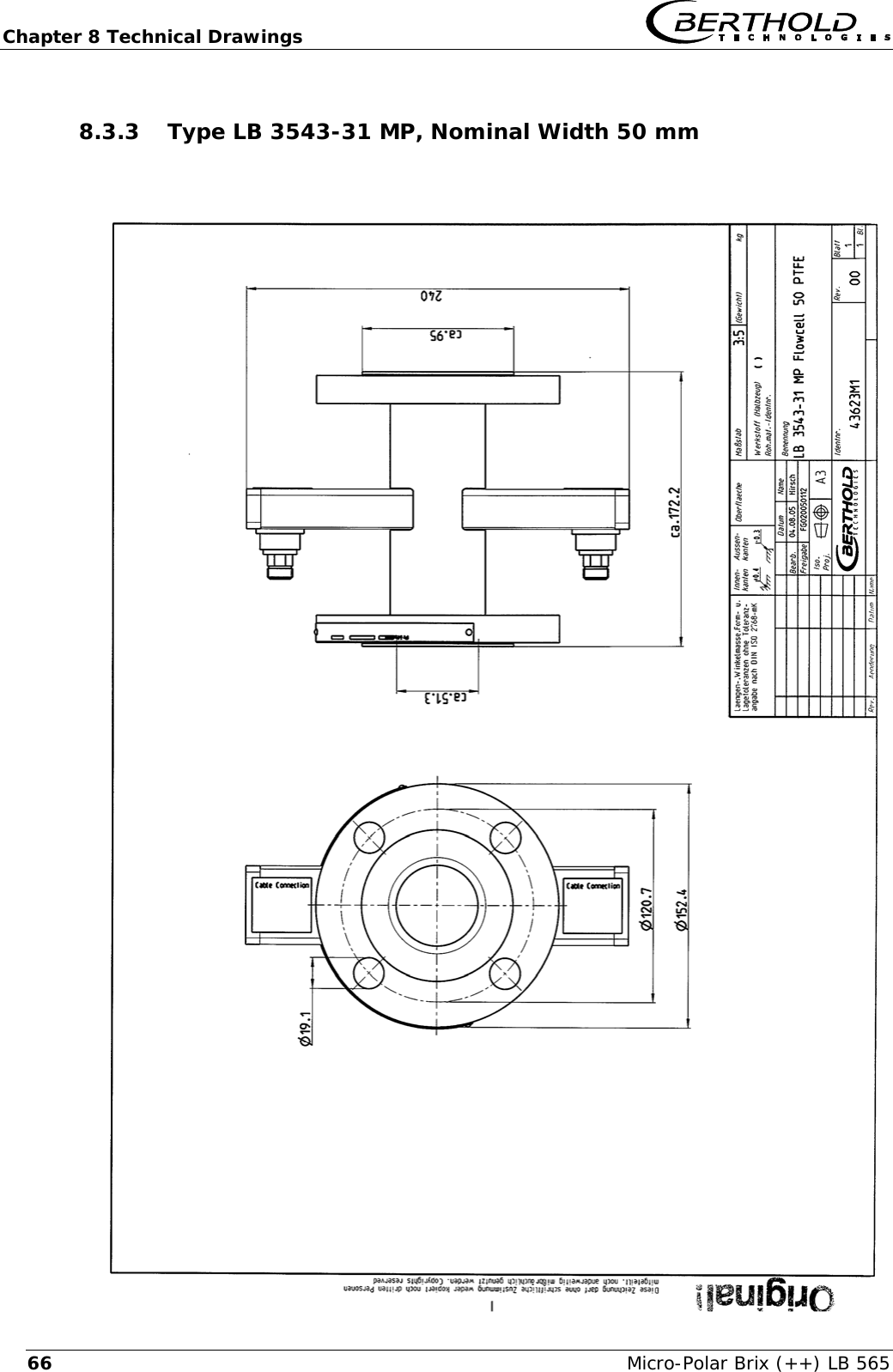
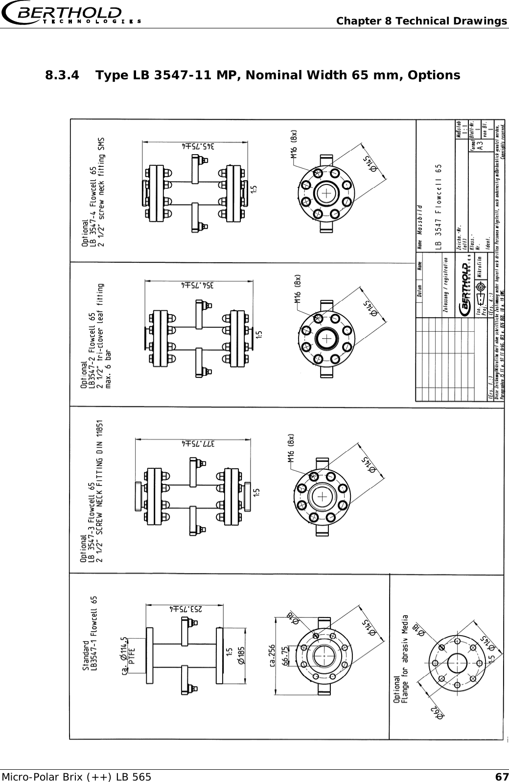
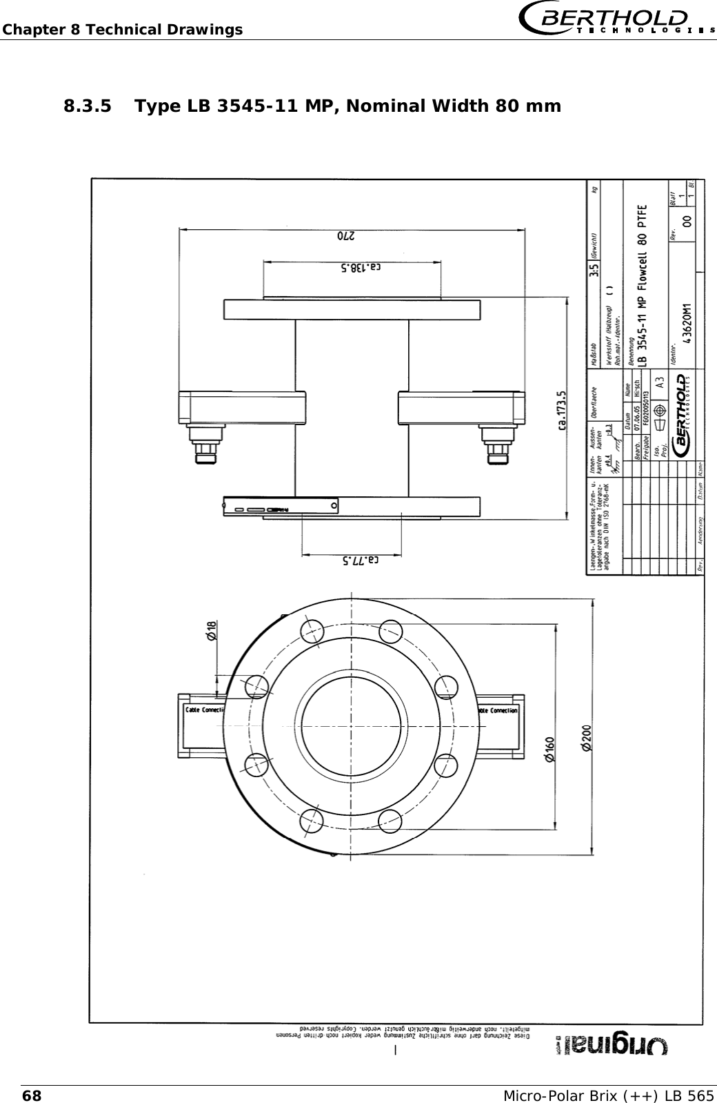
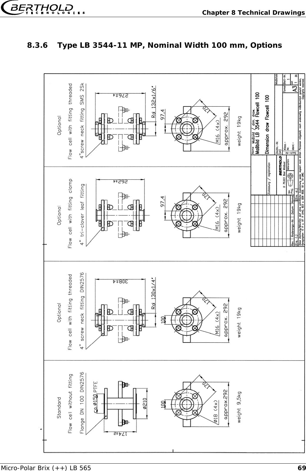
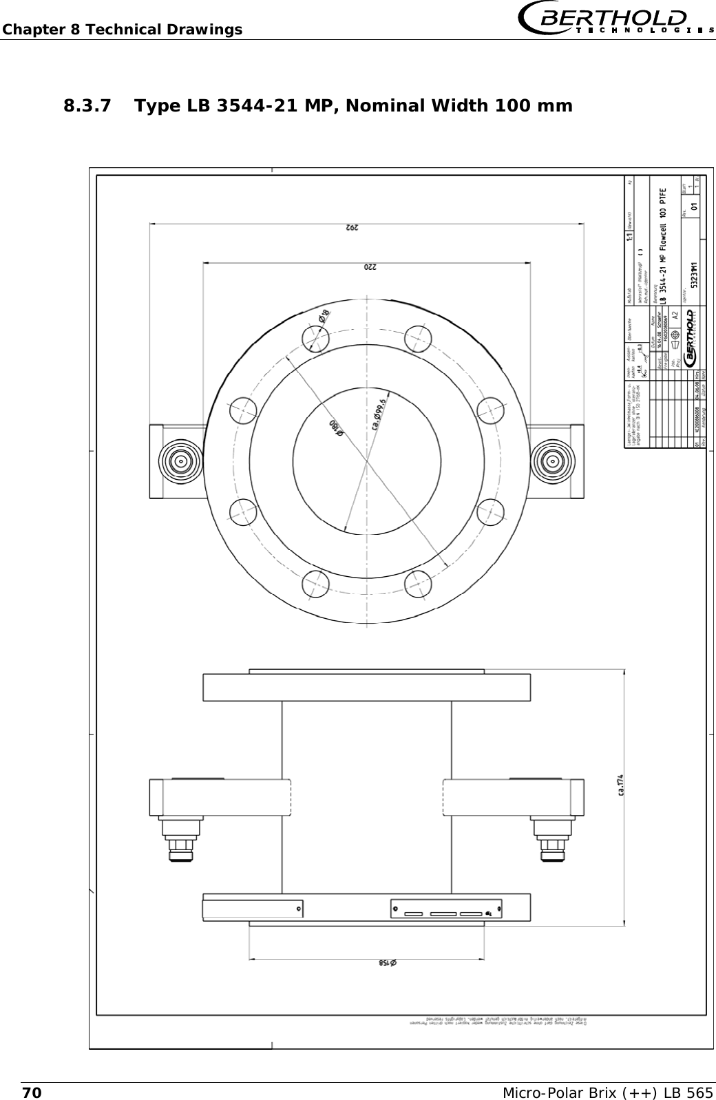
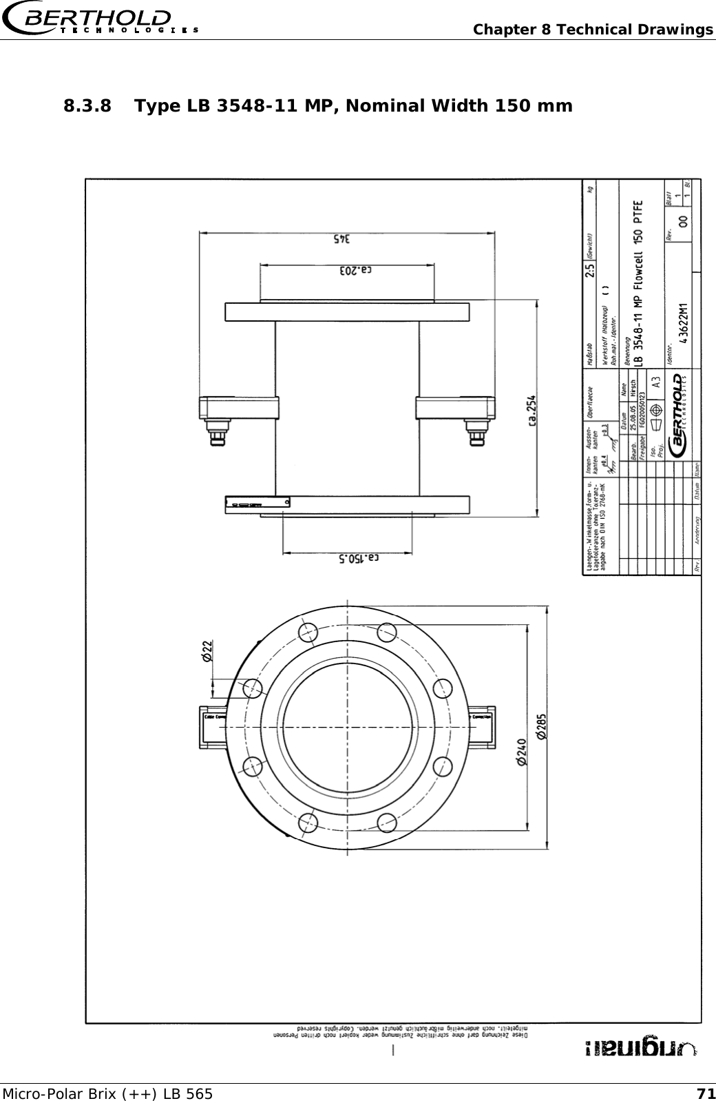
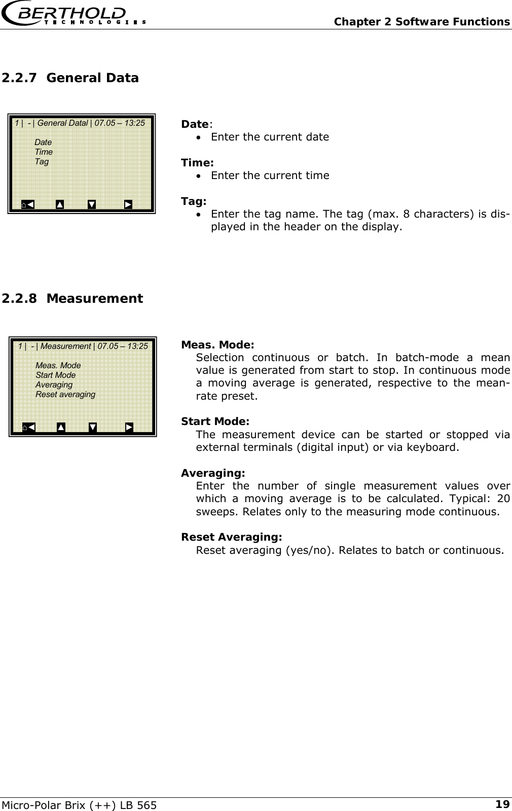
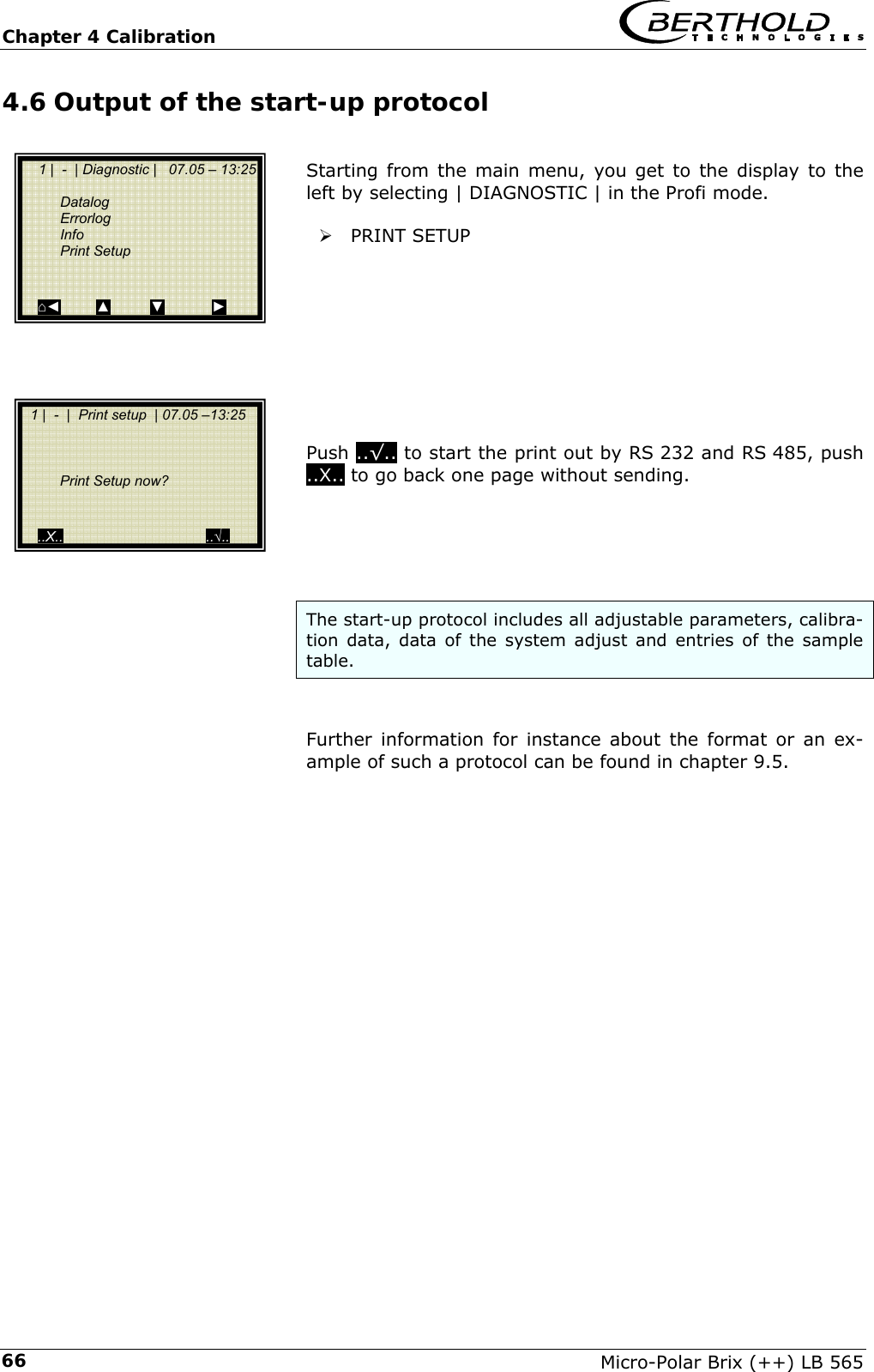
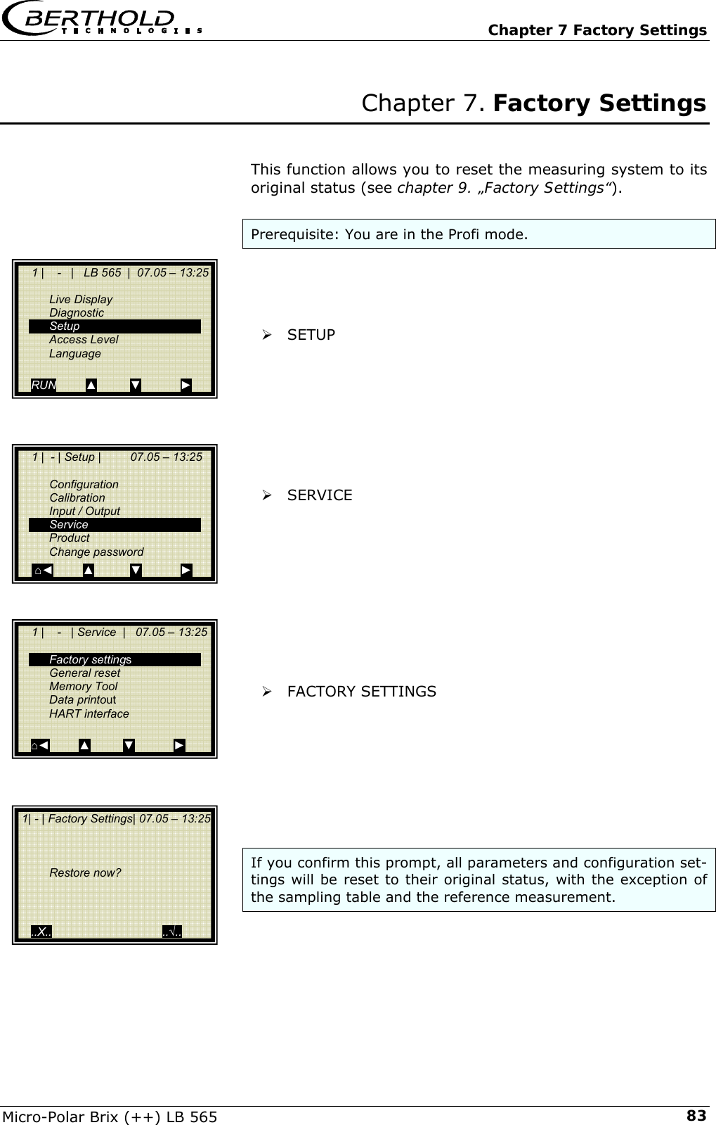
![Chapter 6 Technical Data Micro-Polar Brix (++) LB 565 506.2 Technical Data Sensors Flow cells Application Microwave flow cell with various nominal widths and flanges for measurement on pipelines Material Stainless steel, PTFE lining Process coupling Flange according to DIN EN 1092 Type 05 and ASA Optional with threaded or clamp connector Process pressure Up to 20 bar (relative), depending on nominal width and flange type, see table below Temperature range Product temperature: +10 ... +130°C (283 … 403 K) Ambient temperature: -20 ... +60°C (253 … 333 K) Storage temperature: +10 ... +80°C (283 … 353 K) Connections 2 x HF connections: N-socket, 50 Ω for HF-cable with max. 10 m length Versions Nominal pipe widths from 50 ... 150 mm Dimensions See dimensional drawings in chapter 8 Overview flow cells Designation ID-No. Nominal width [mm] Flange Pressure [bar] LB 3543-11 MP 43617 50 DN 50 / PN 16 16 LB 3547-11 MP 43619 65 DN 65 / PN 40 20 LB 3545-11 MP 43620 80 DN 80 / PN 16 16 LB 3544-11 MP 43621 100 DN 100 / PN 6 6 LB 3544-21 MP 53231 100 DN 100 / PN 16 16 LB 3548-11 MP 43622 150 DN 150 / PN 16 16 LB 3543-31 MP 43623 50 ASA 2’’ / 150 PSI 16 LB 3547-31 MP 43624 65 ASA 2.5’’ / 300 PSI 20 LB 3545-31 MP 43625 80 ASA 3’’ / 150 PSI 16 LB 3544-31 MP 43626 100 ASA 4’ / 150 PSI 16 LB 3548-31 MP 43627 150 ASA 6’’ / 150 PSI 16](https://usermanual.wiki/Berthold-Technologies/FCC01X12/User-Guide-1100454-Page-50.png)
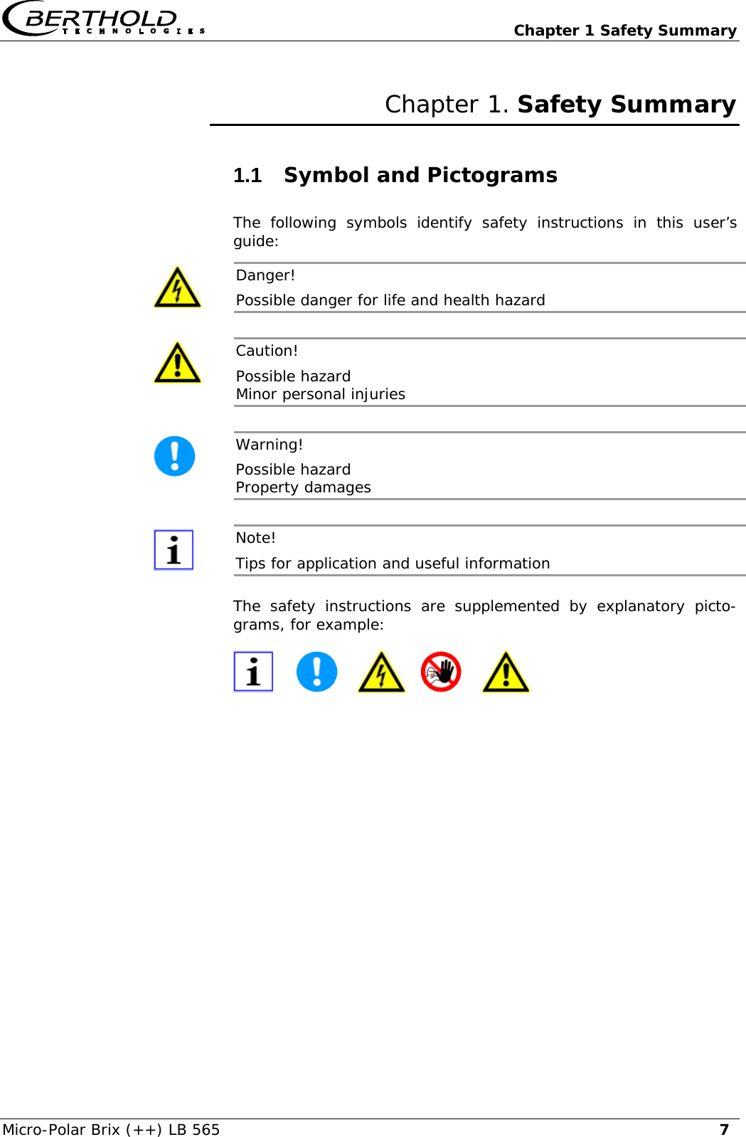
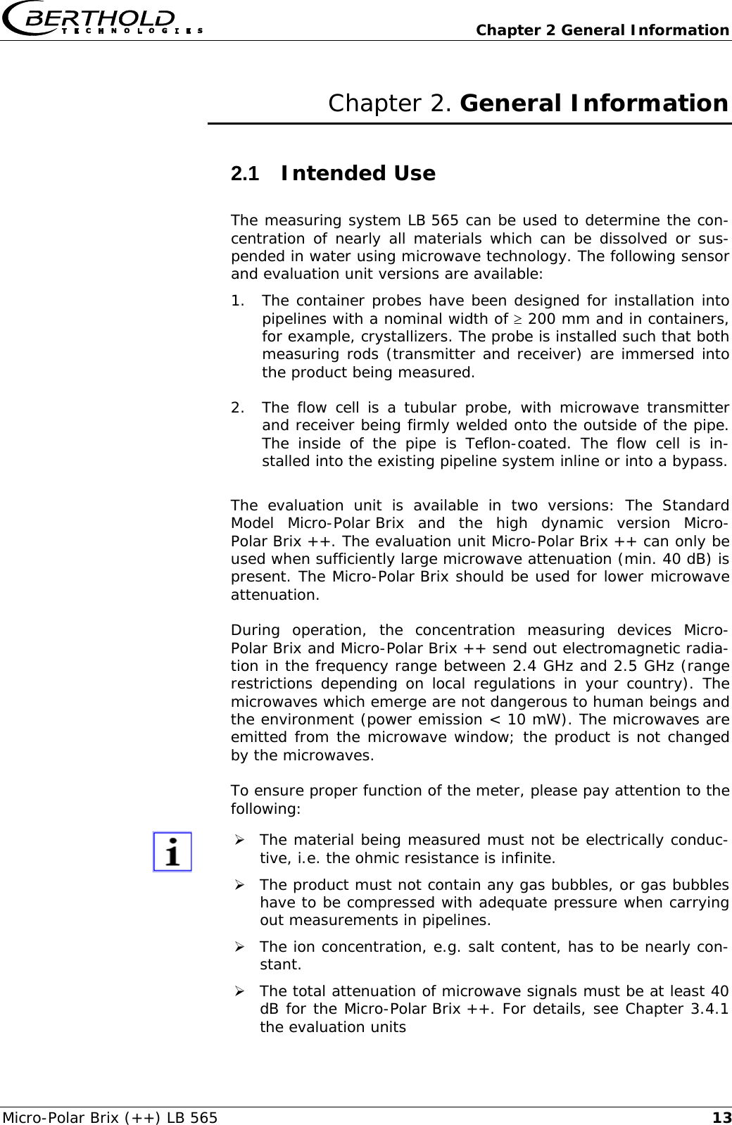
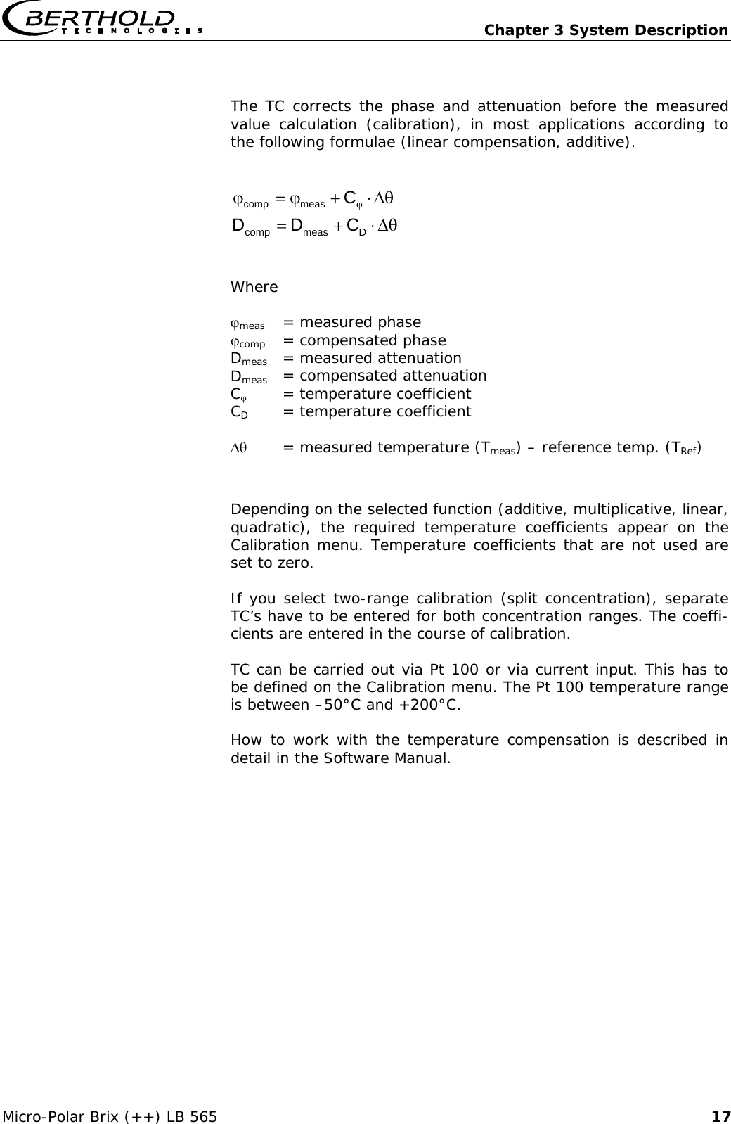
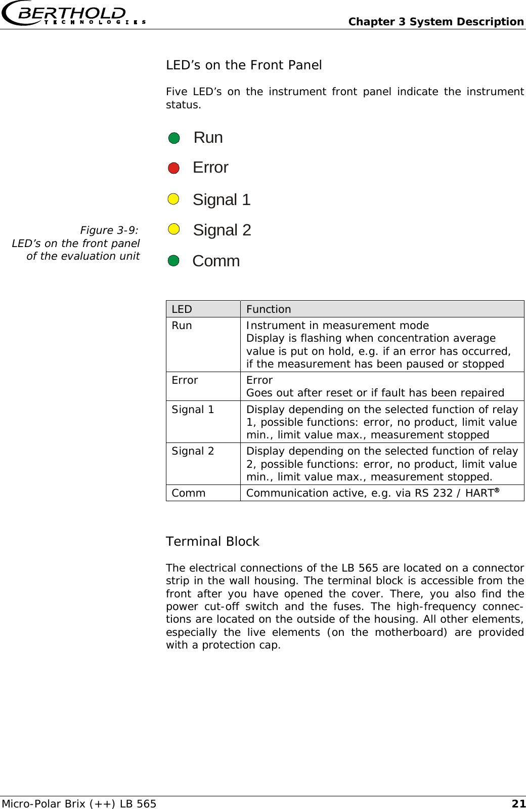
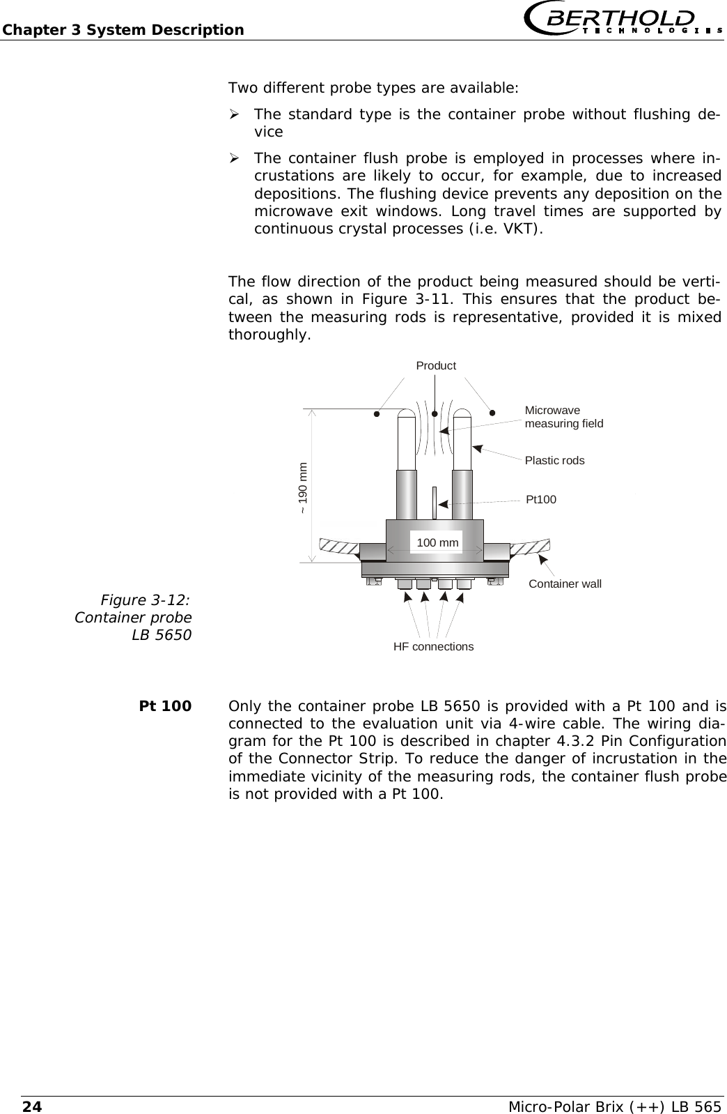
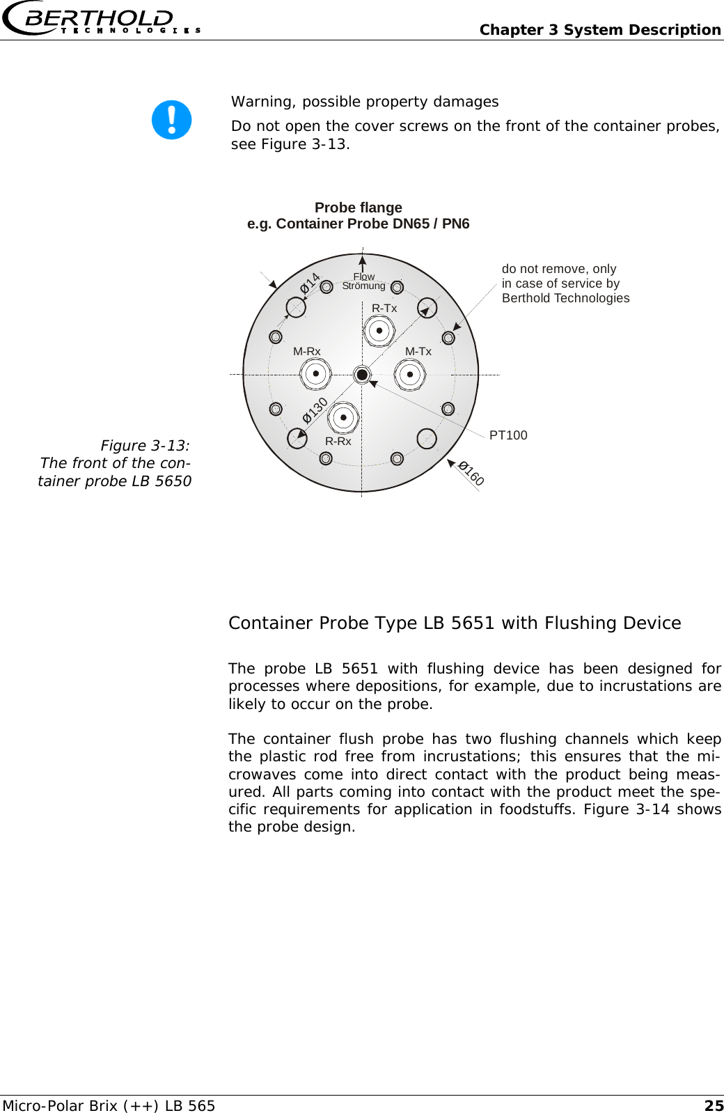
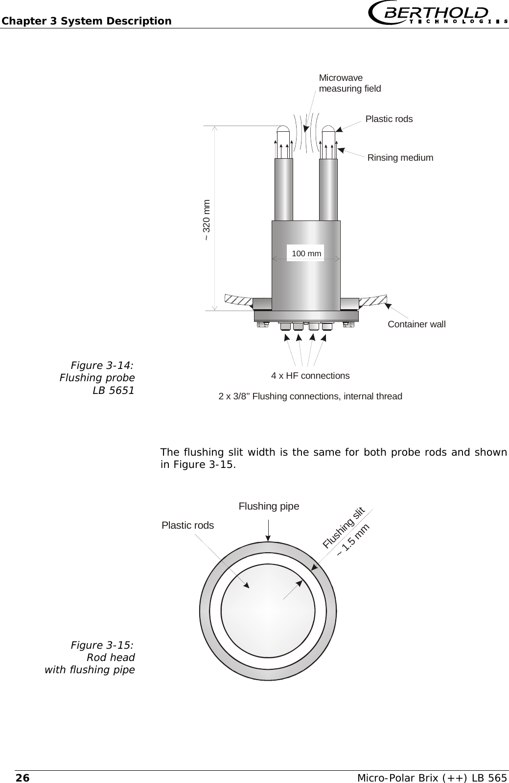
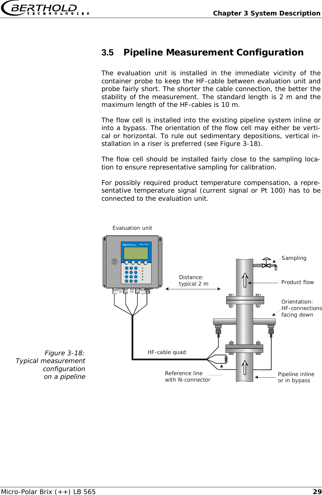
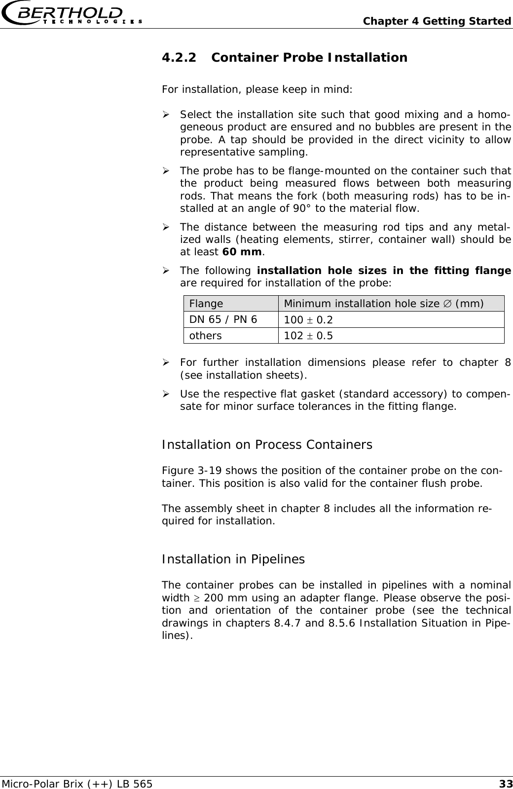
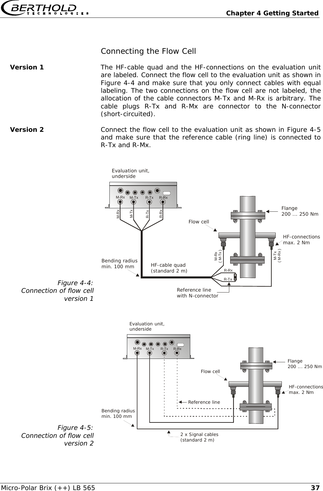
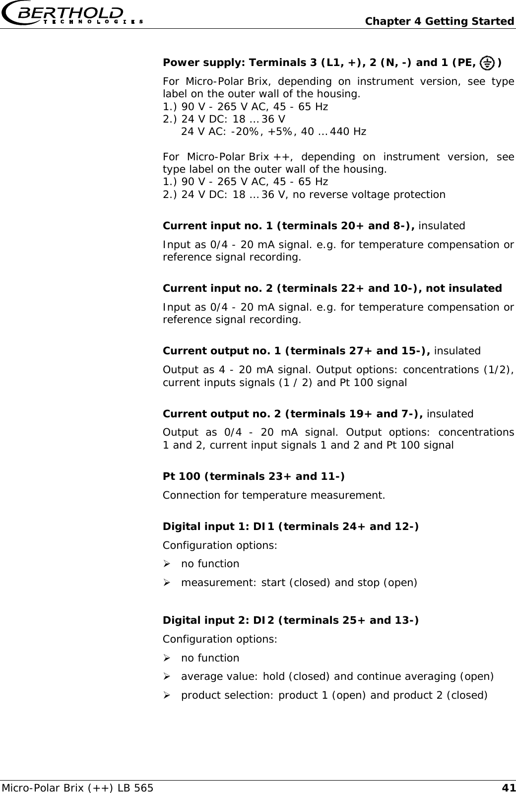
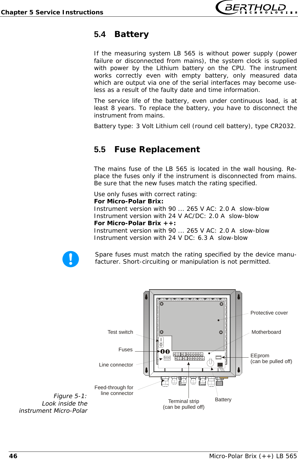
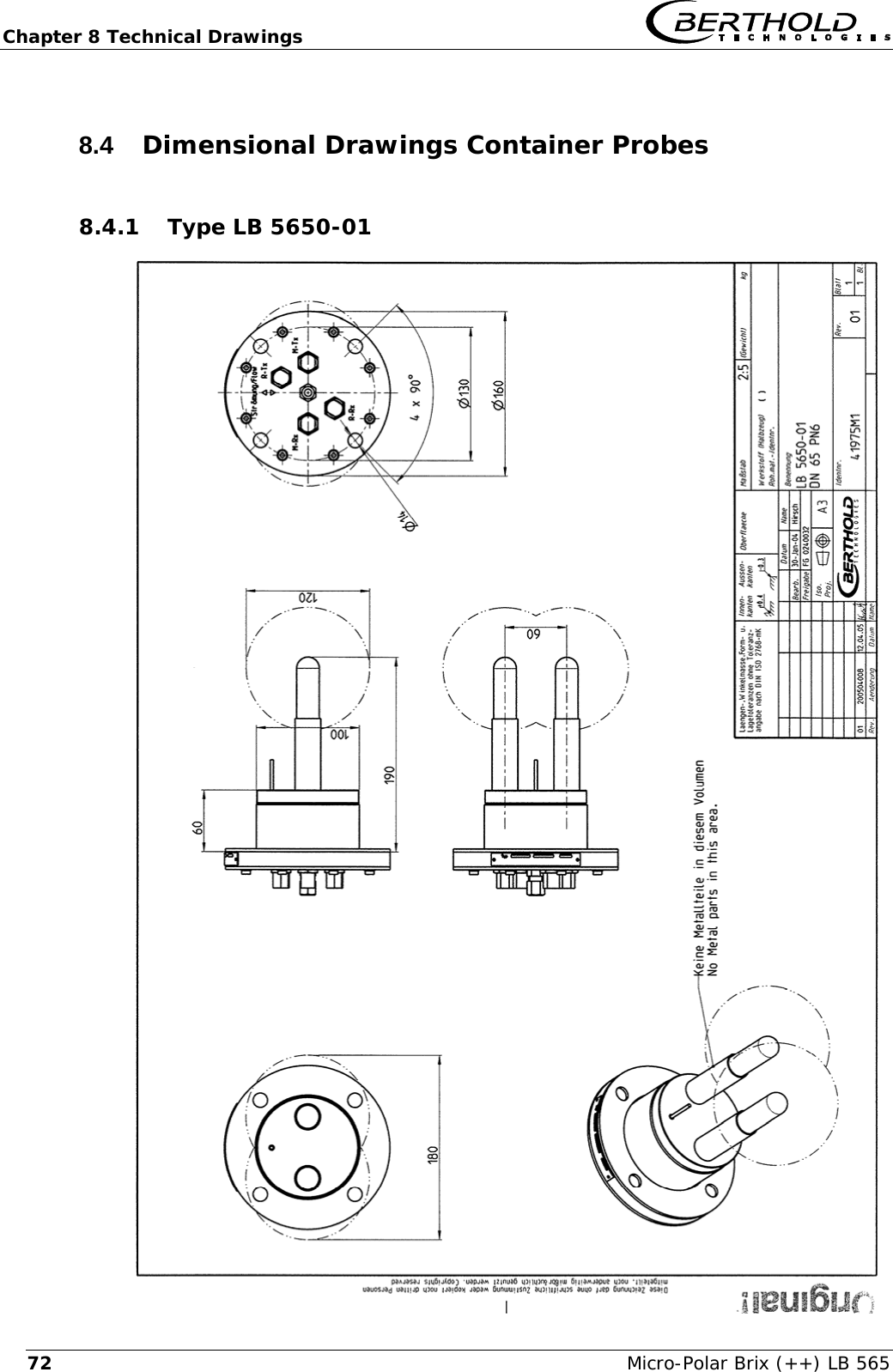
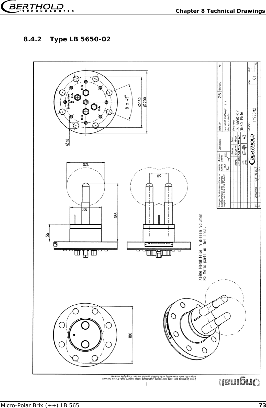
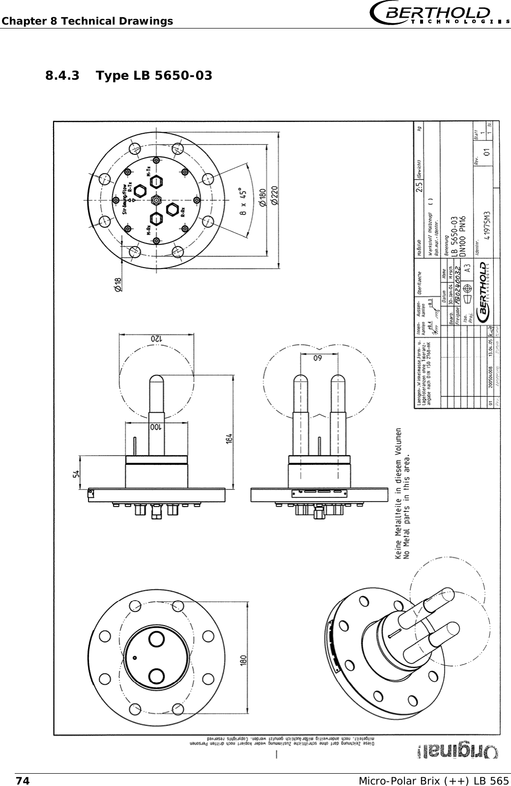
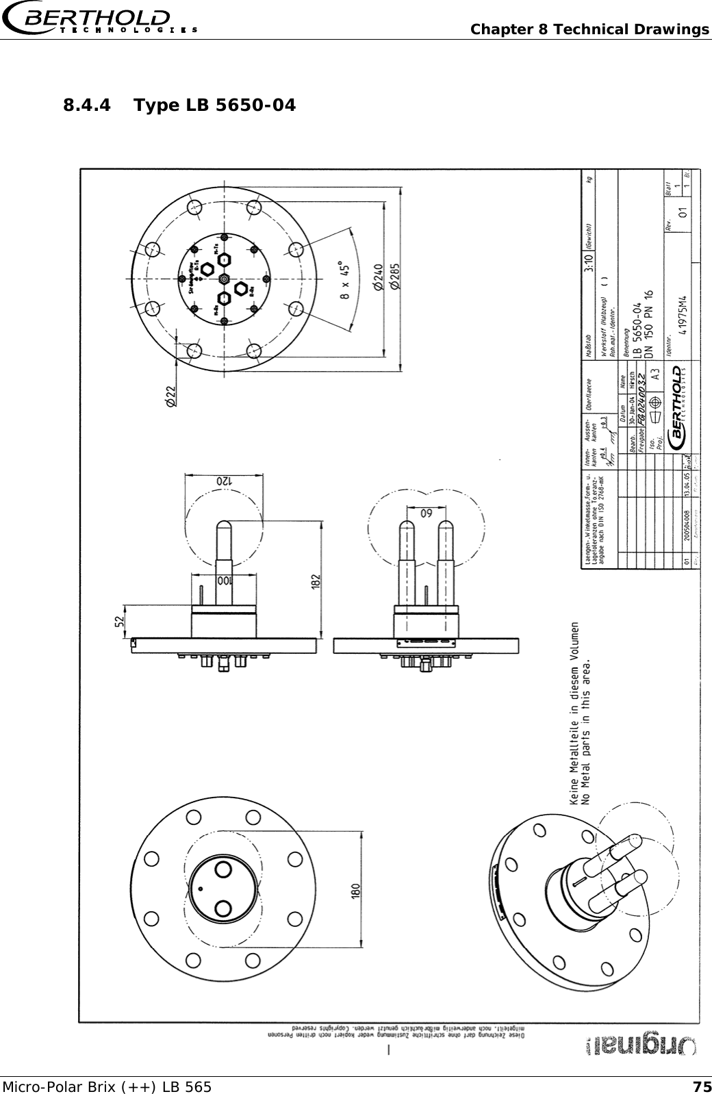
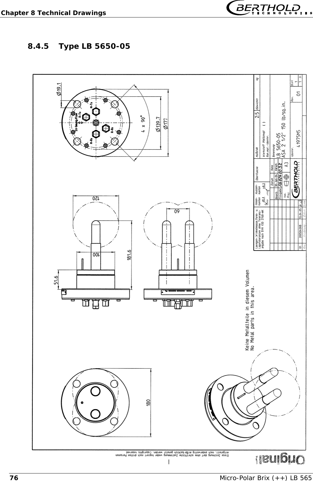
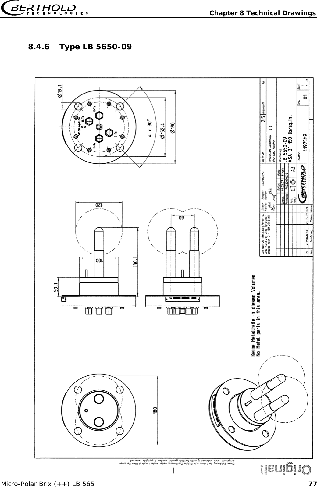
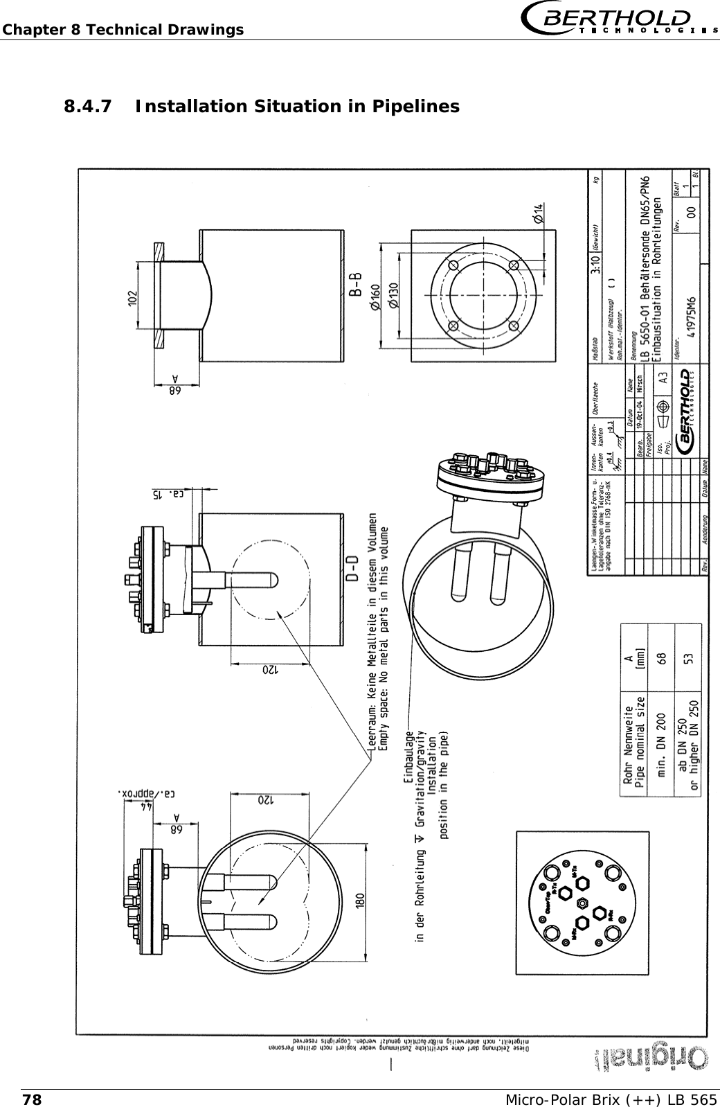
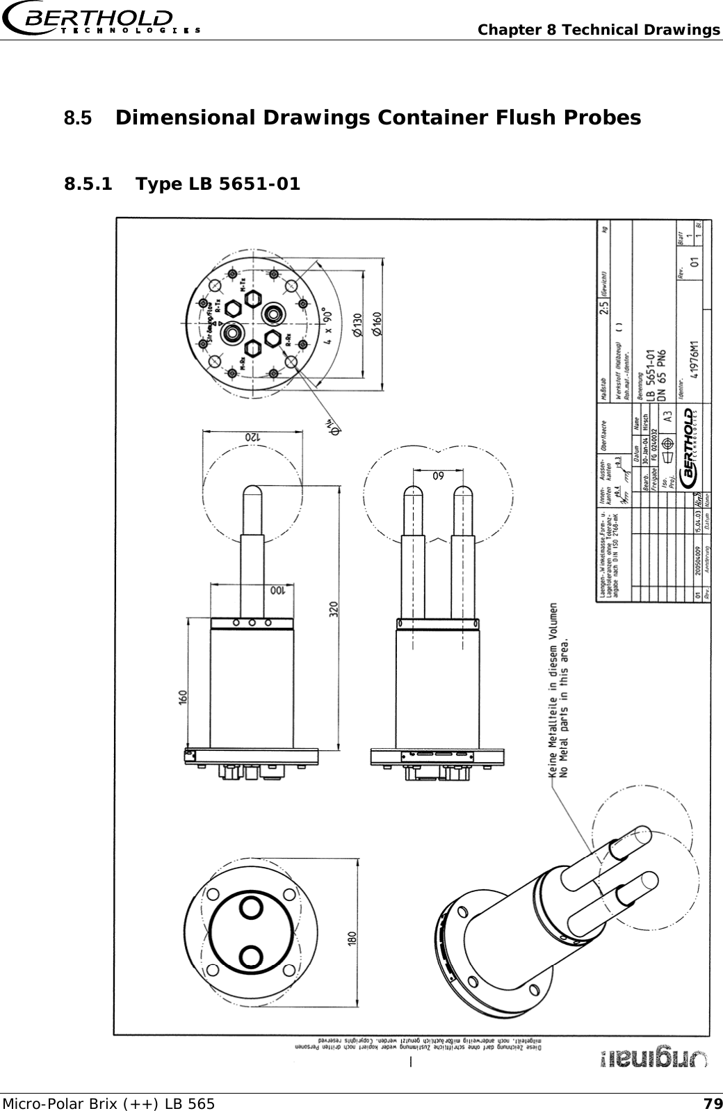
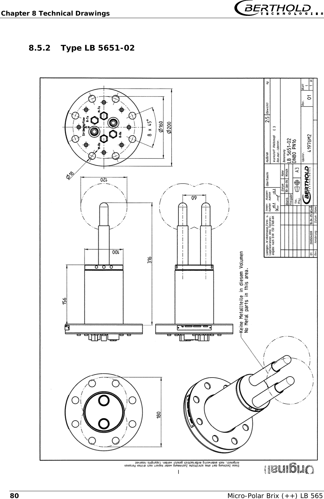
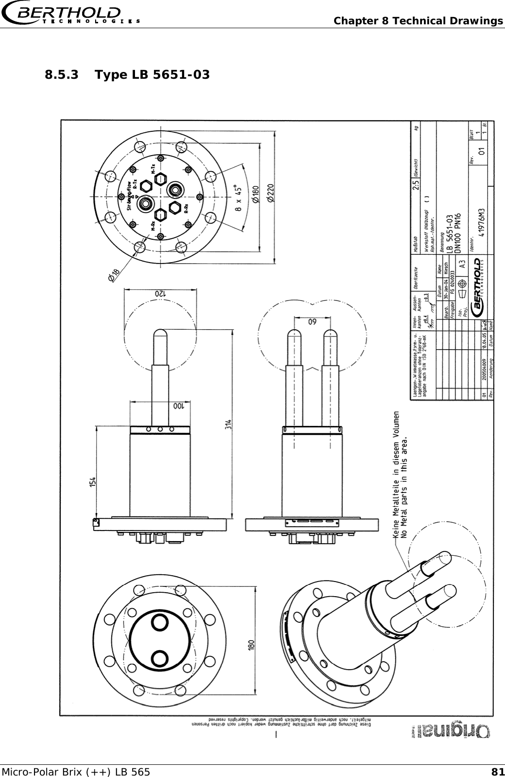
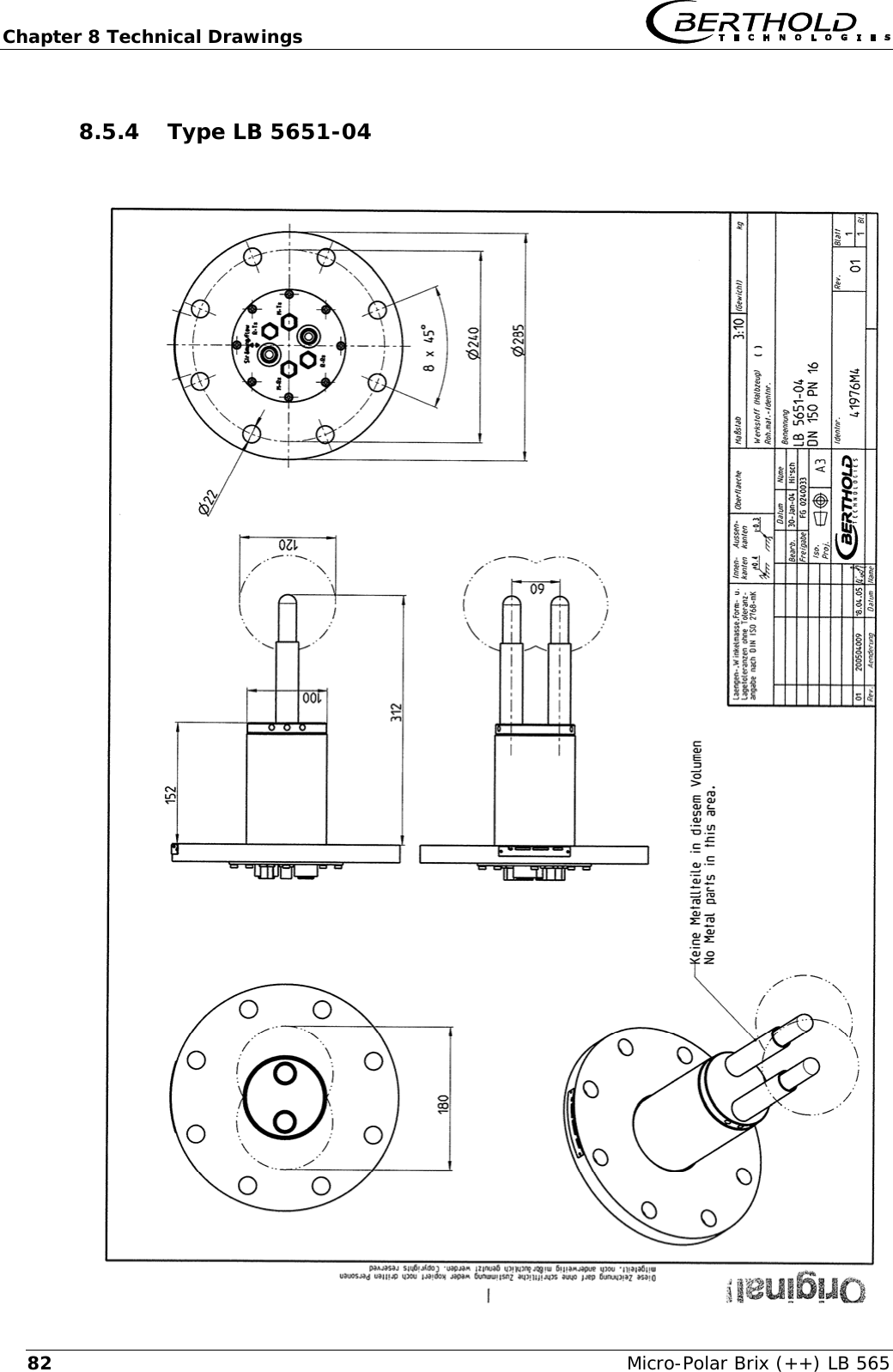
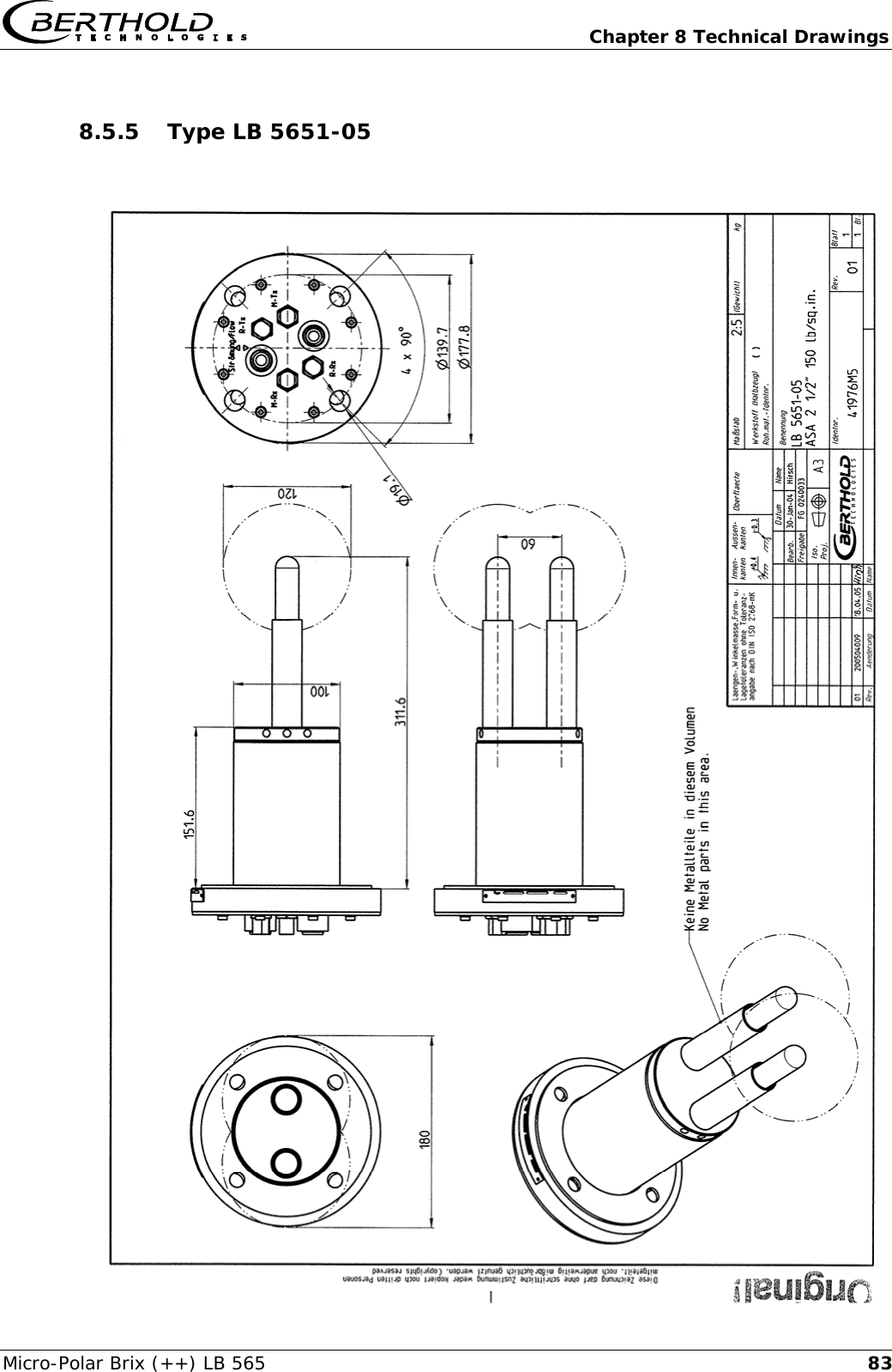
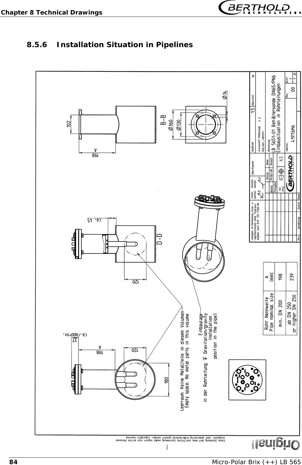
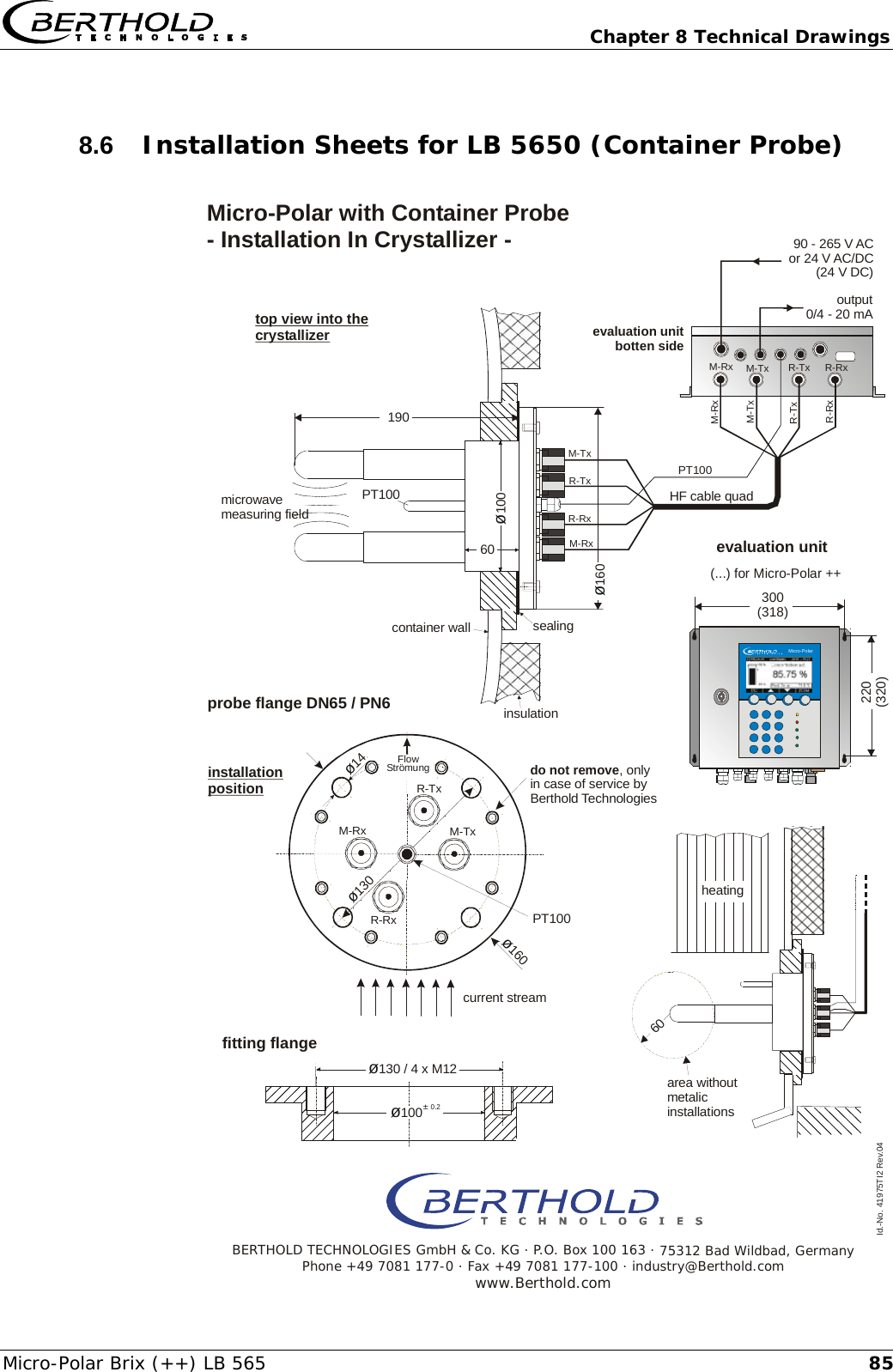
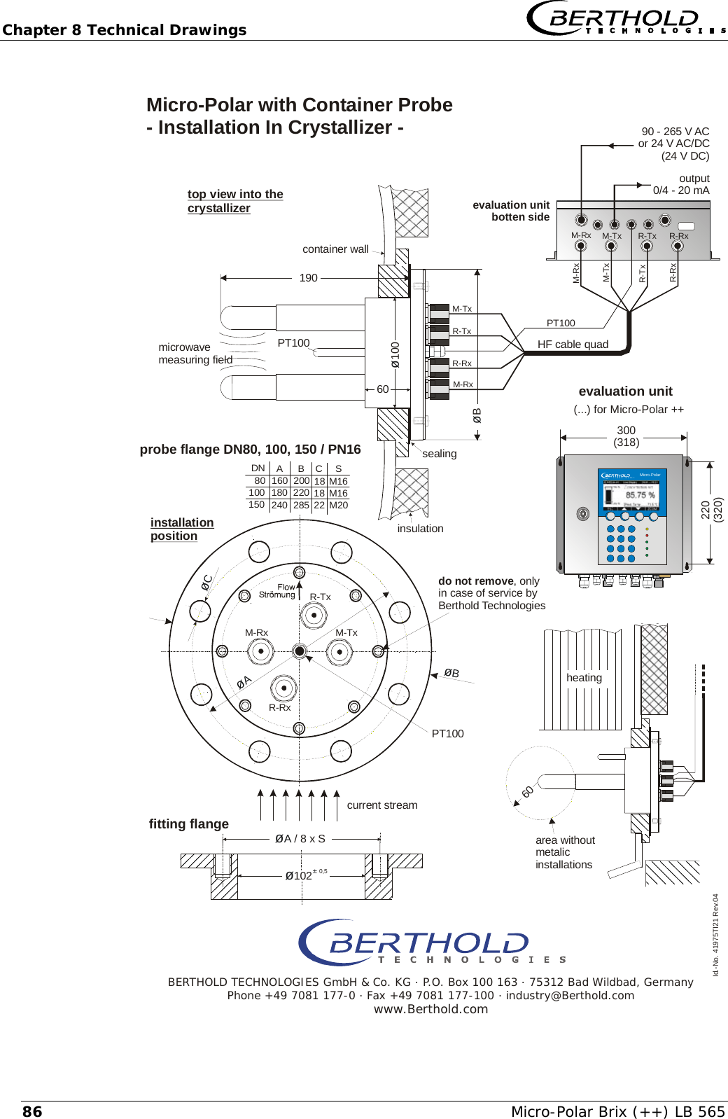
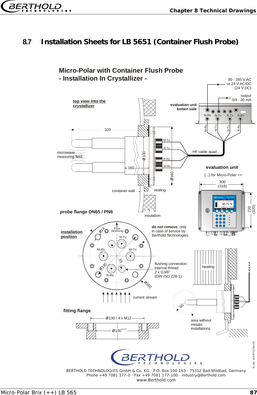
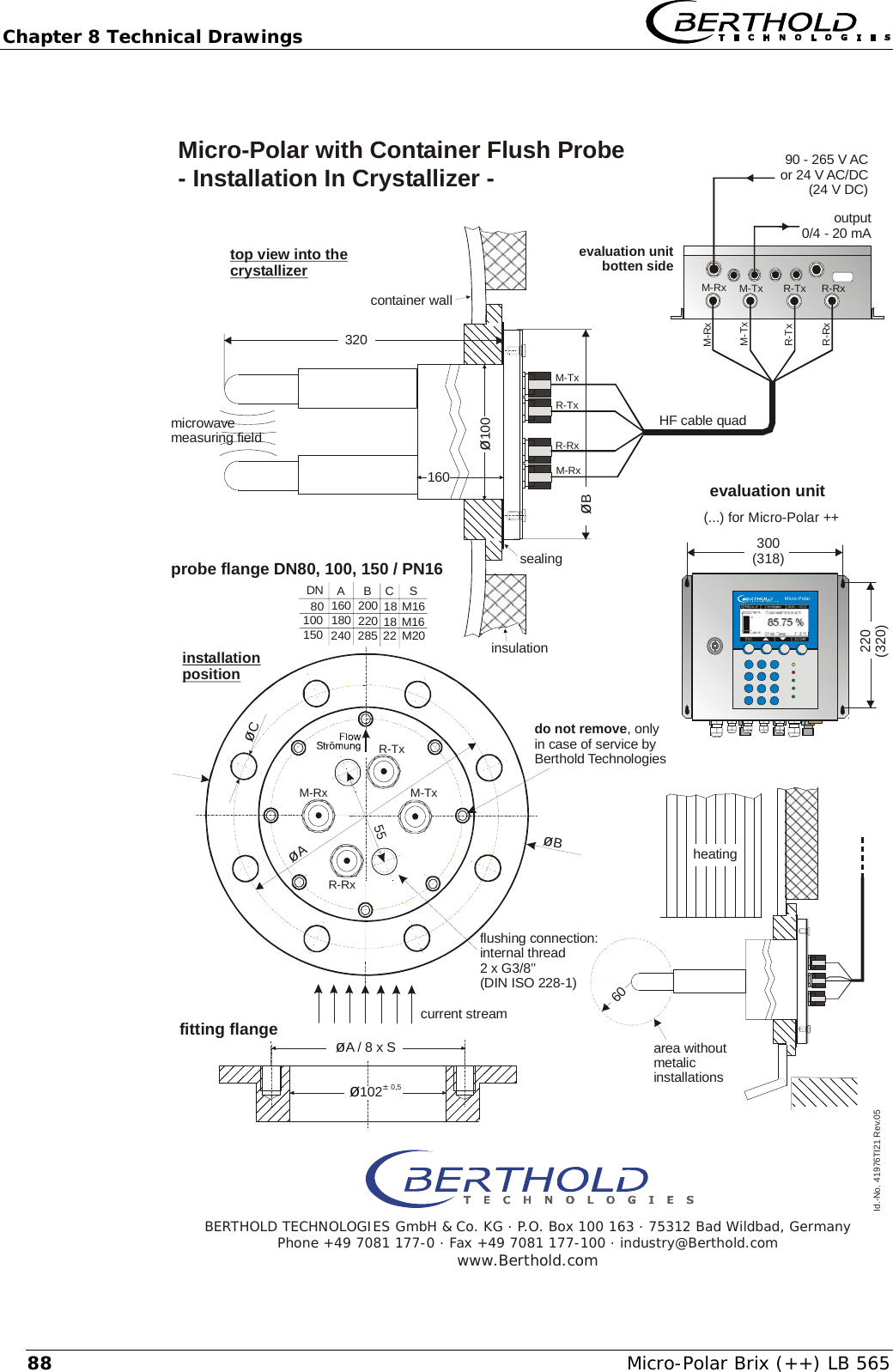
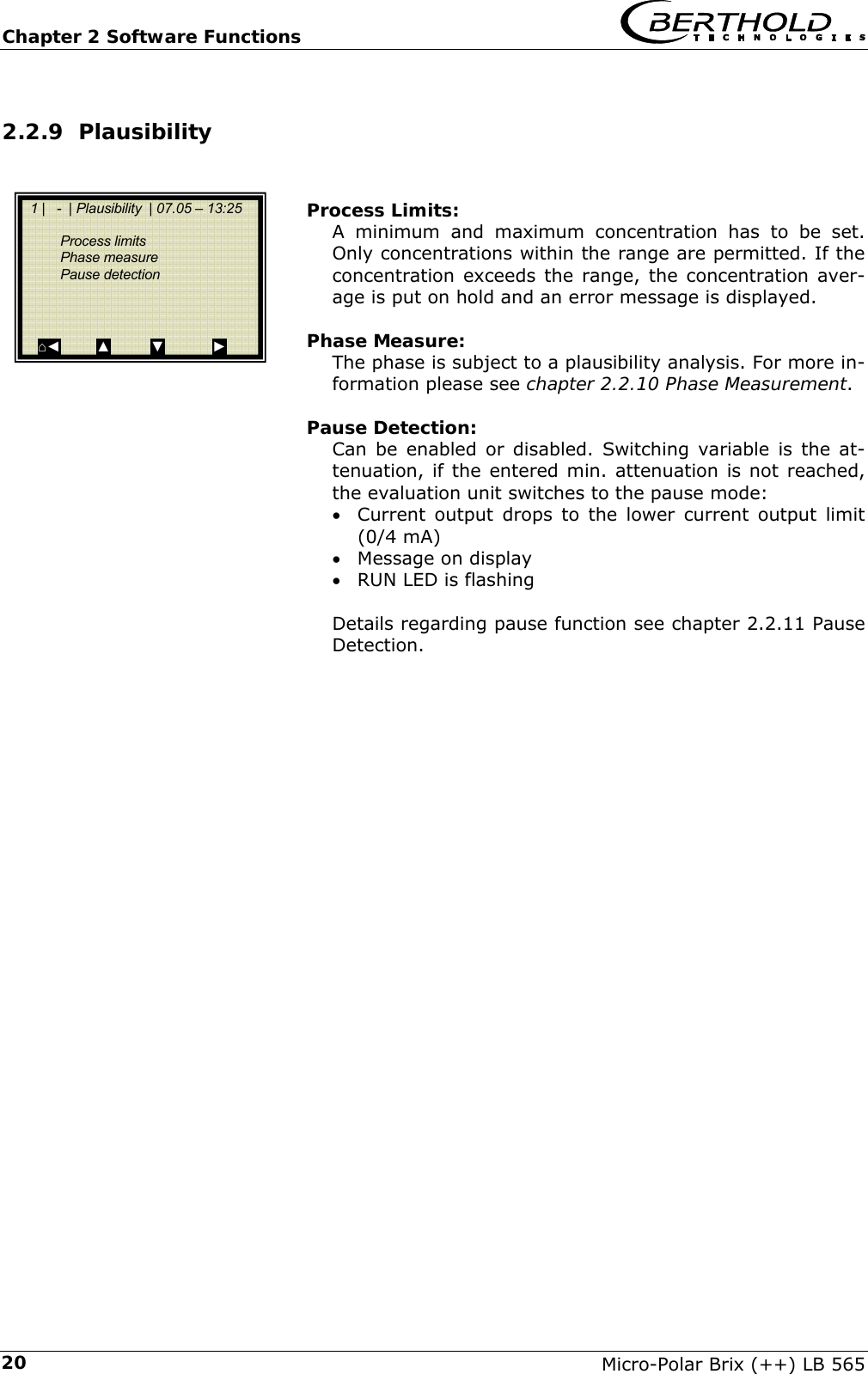
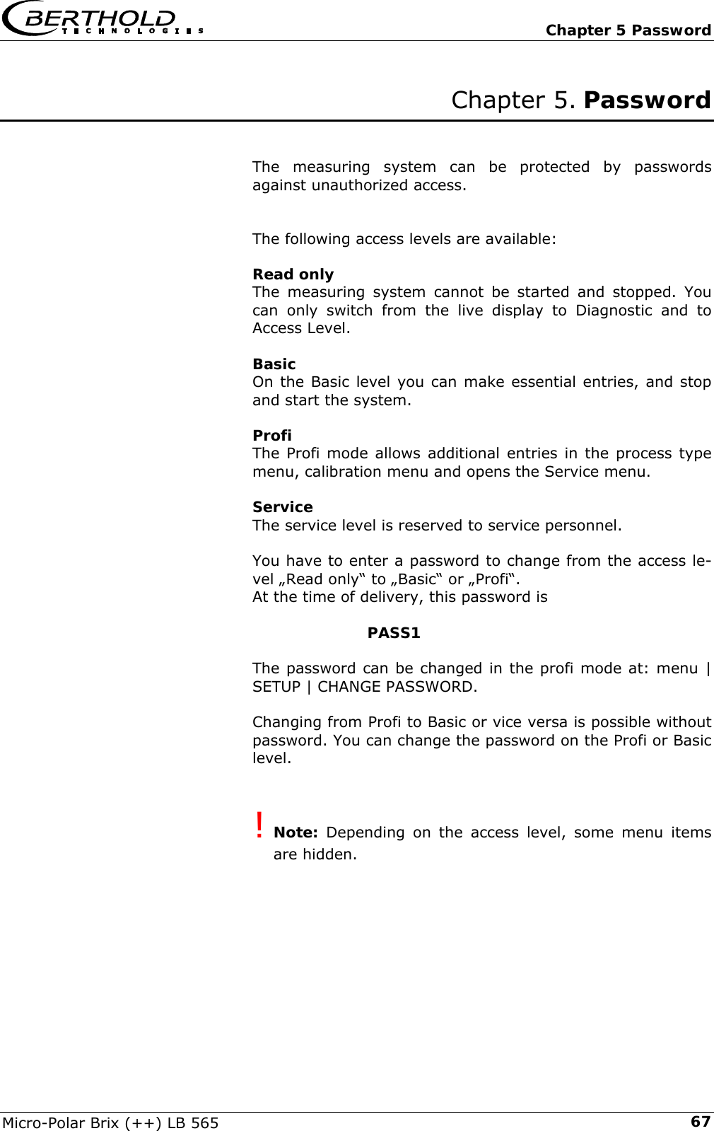
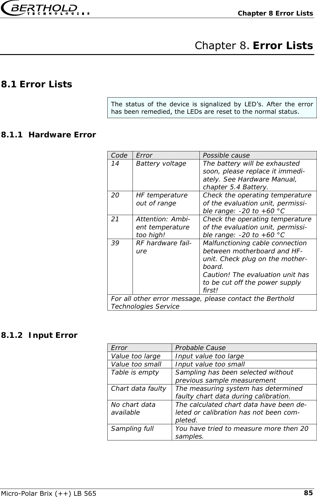
![Chapter 6 Technical Data Micro-Polar Brix (++) LB 565 51 Container probes Application Container probes with and without flushing device for concentration measurement in process containers and pipelines with nominal width ≥ 200 mm. Material Plastic rod, stainless steel 1.4301 PT100 connection cable: Silicon / Teflon Process coupling Flange according to DIN EN 1092 Type 05 DN65 / PN6, DN 80, 100, 150 / PN16; ASA flange 2.5’’, 3’’ / 150 PSI (others on request) Process pressure Up to 16 bar (relative), depending on model Temperature range Product temperature: +10 ... +120°C (283 … 393 K) Ambient temperature: -20 ... +60°C (253 … 333 K) Storage temperature: +10 ... +80°C (283 … 353 K) Connections 4 x HF connections: N-socket, 50 Ω for HF-cable with max. 10 m length Dimensions See dimensional drawings in chapter 8 Accessory sealing washer Material Klingersil C-4400 Thickness 3 mm Overview container probes and sealing washers Designation ID-No. Flange Pressure [bar] ID-No. sealing washer LB 5650-01 41975-01 DN 65 / PN 6 6 32175 LB 5650-02 41975-02 DN 80 / PN 16 16 33717 LB 5650-03 41975-03 DN 100 / PN 16 16 46661 LB 5650-04 41975-04 DN 150 / PN 16 16 46664 LB 5650-05 41975-05 ASA 2.5’’ / 150 PSI 16 46665 LB 5650-09 41975-09 ASA 3’’ / 150 PSI 16 LB 5651-01 41976-01 DN 65 / PN 6 6 32175 LB 5651-02 41976-02 DN 80 / PN 16 16 33717 LB 5651-03 41976-03 DN 100 / PN 16 16 46661 LB 5651-04 41976-04 DN 150 / PN 16 16 46664 LB 5651-05 41976-05 ASA 2.5’’ / 150 PSI 16 46665](https://usermanual.wiki/Berthold-Technologies/FCC01X12/User-Guide-1100454-Page-51.png)
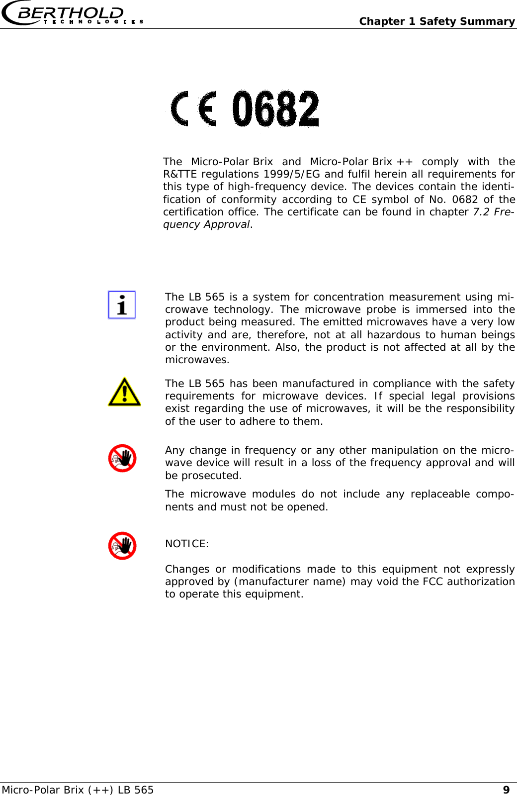
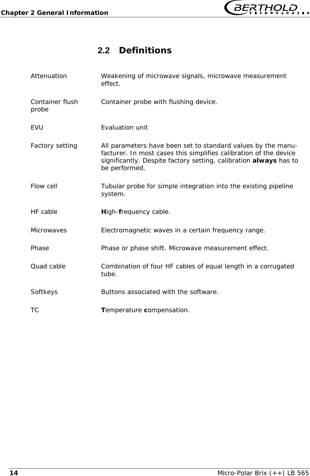
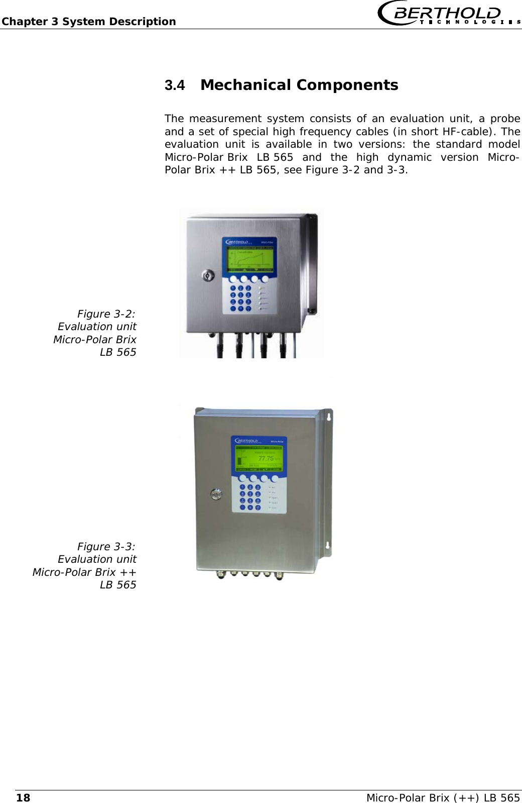
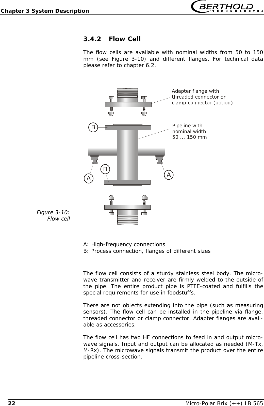
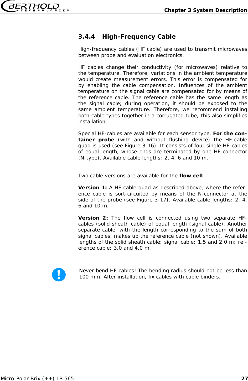
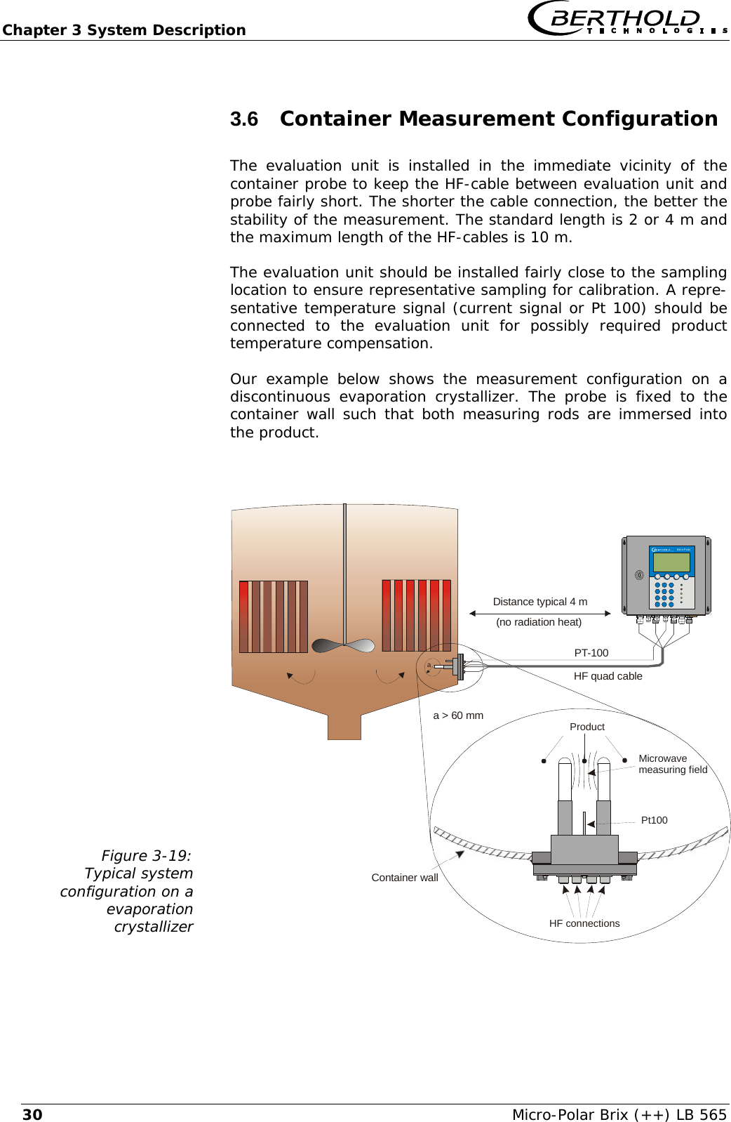
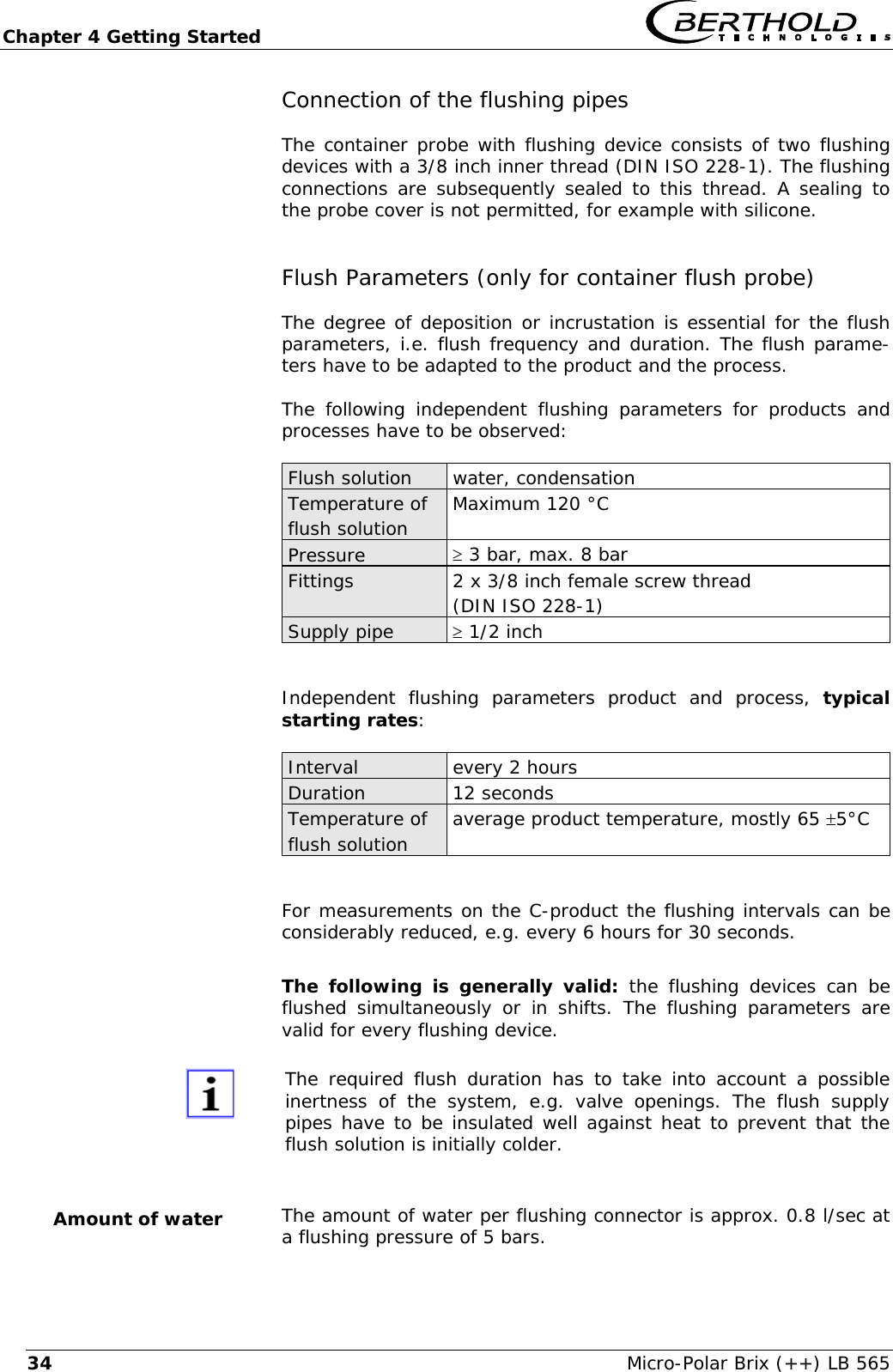
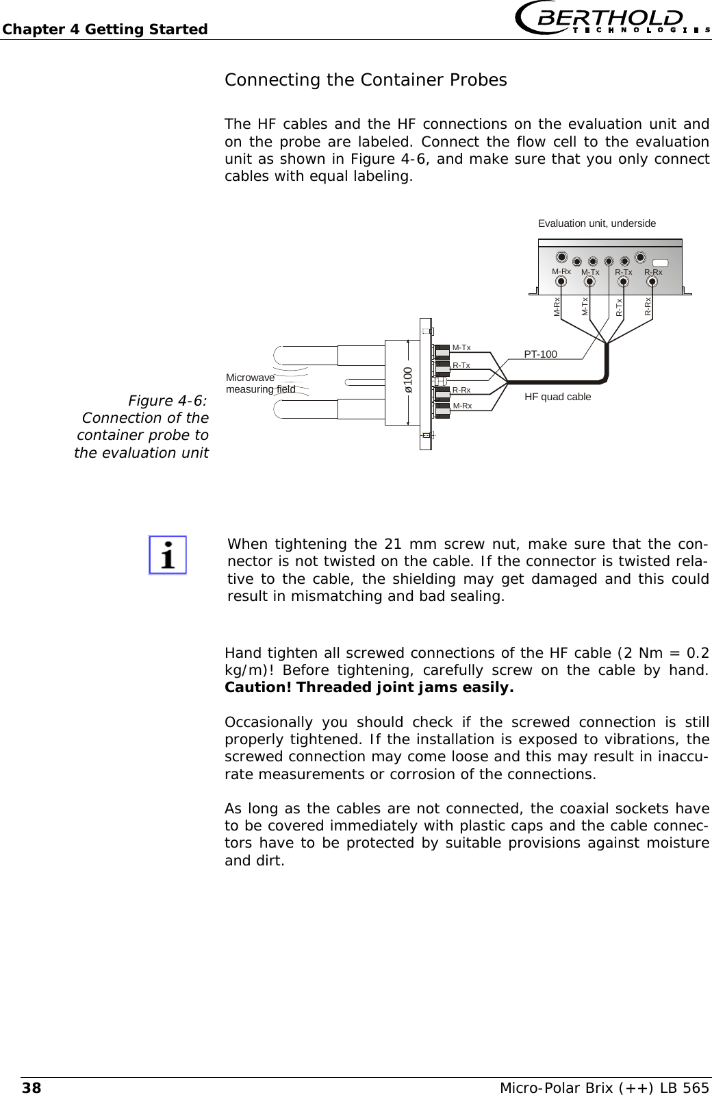
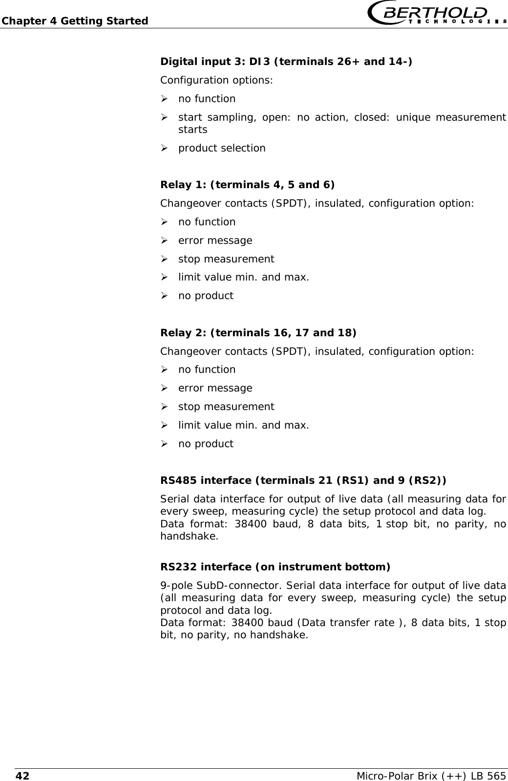
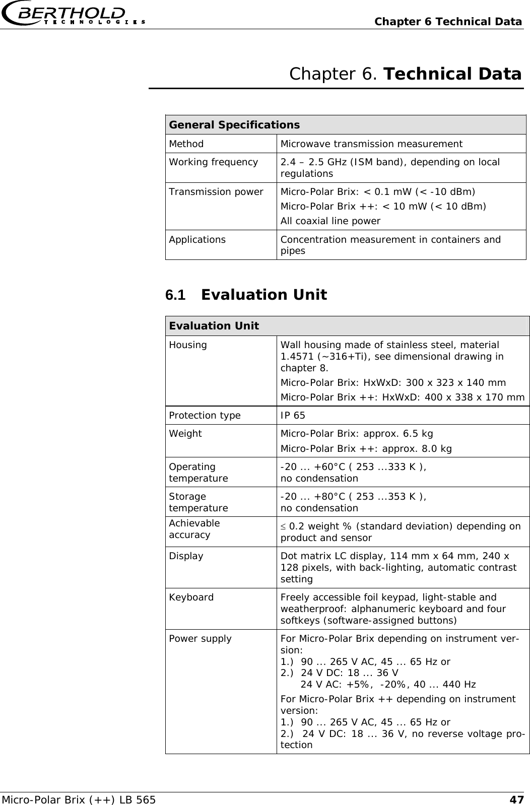
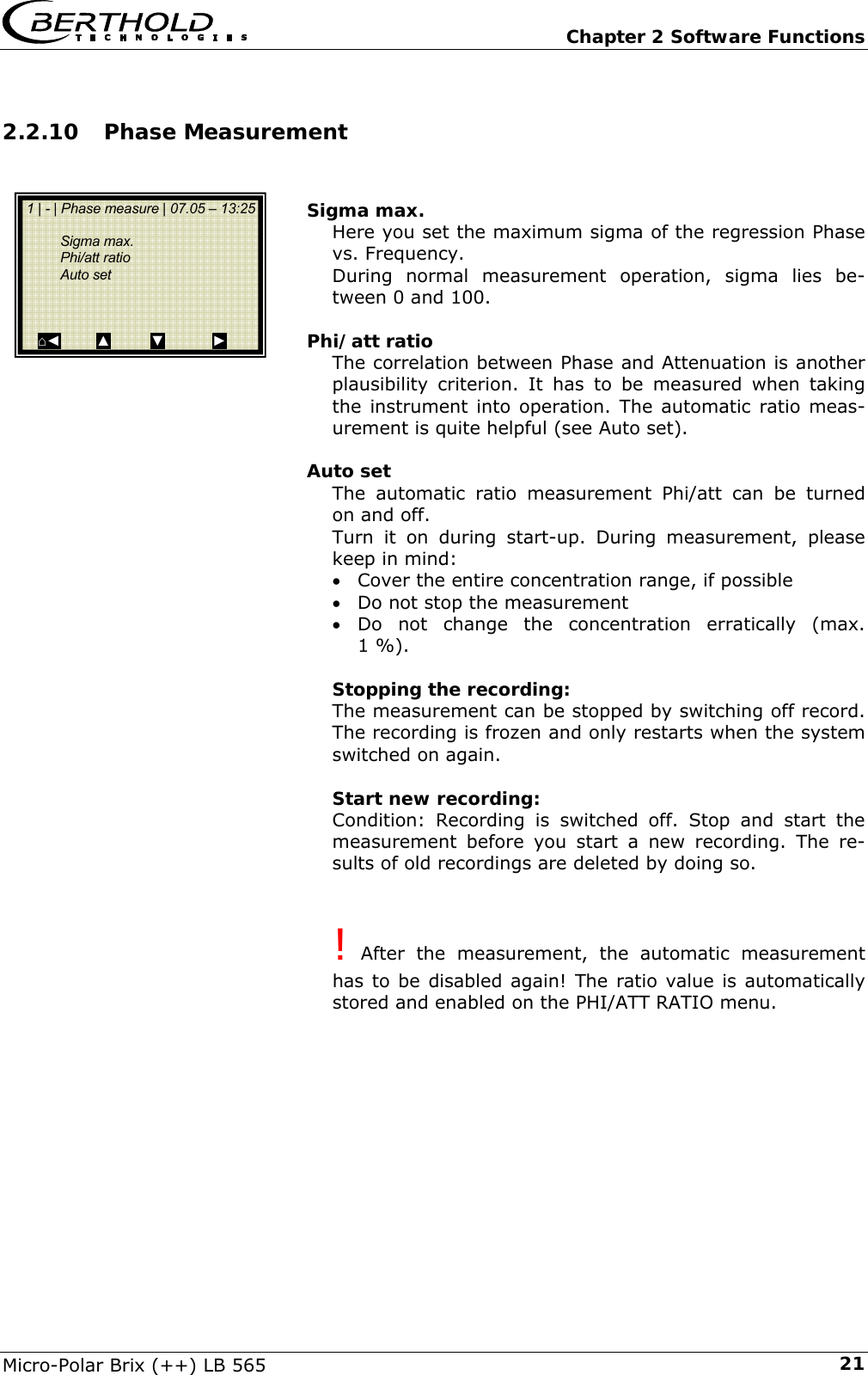
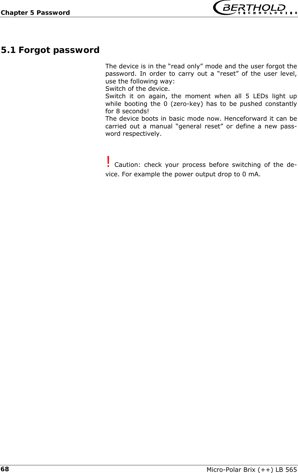
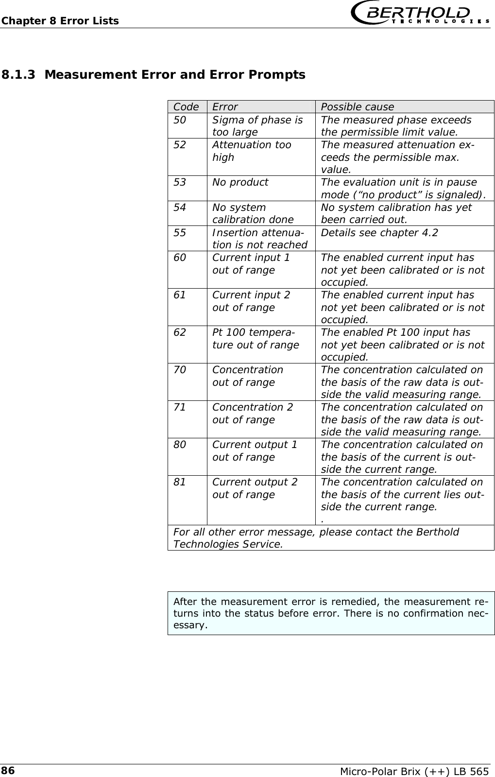
![Chapter 6 Technical Data Micro-Polar Brix (++) LB 565 536.4 Format of Serial Data Output RS 232 and RS 485 Header Date·Time→Flags→Status→Product→Att→Phi→R2→Tint→IN1→IN2→Pt 100→C→Cm→C2→C2m¶ Following lines 01.01.2005·00:00:00→0000→0→1→0.43→5.30→0.07→0.0→0.0→0.0→0.0→75.36→75.00→0.00→0.00¶ 1 2 3 4 5 6 7 8 9 10 11 12 13 14 15 Column no. Description Format 1 Date and time DD.MM.YY·HH:MM:SS 2 Flags (for test purposes) 4 digits, HEX 3 Status: Information on quality of last measurement 0 : measurement OK < 0 : error 4 Product number X (1 to 4) 5 Attenuation [dB] X.XX 6 Phase [°/GHz] X.XX 7 Statistical spread of phase regression X.XX 8 Instrument temperature [temperature unit] X.X 9 Current input 1 [unit of current input] X.X 10 Current input 2 [unit of current input] X.X 11 Pt 100 temperature [temperature unit] X.X […] by selection of unit g/cm3 12 Concentration 1 live X.XX [X.XXXX] 13 Concentration 1 averaged X.XX [X.XXXX] 14 Concentration 2 live X.XX [X.XXXX] 15 Concentration 2 averaged X.XX [X.XXXX] Special characters “→” Tabulation “¶” Carriage return + Line feed “·” Blank character](https://usermanual.wiki/Berthold-Technologies/FCC01X12/User-Guide-1100454-Page-53.png)


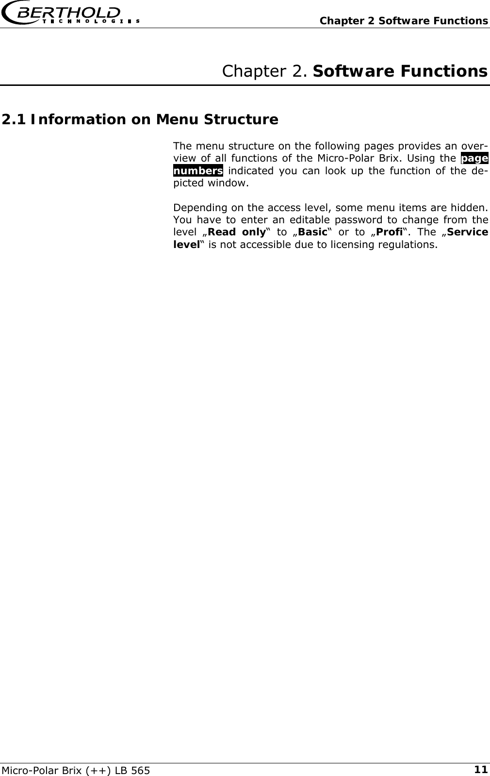
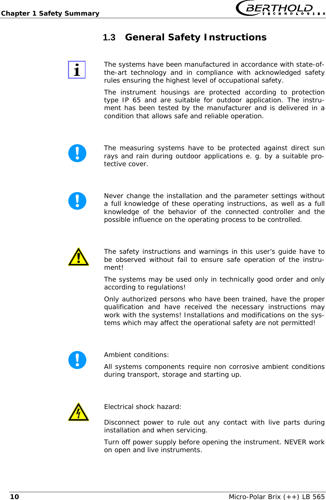
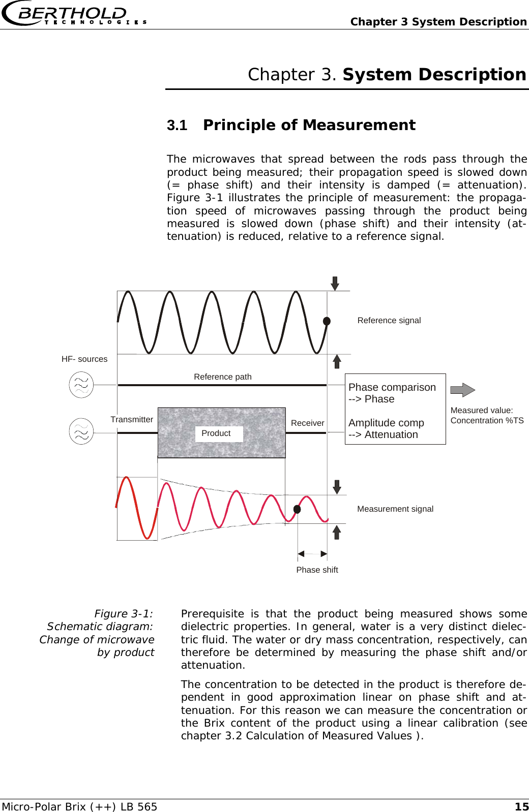
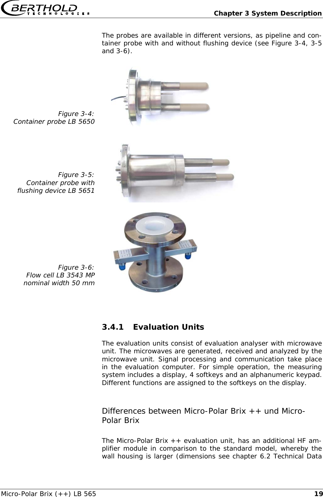
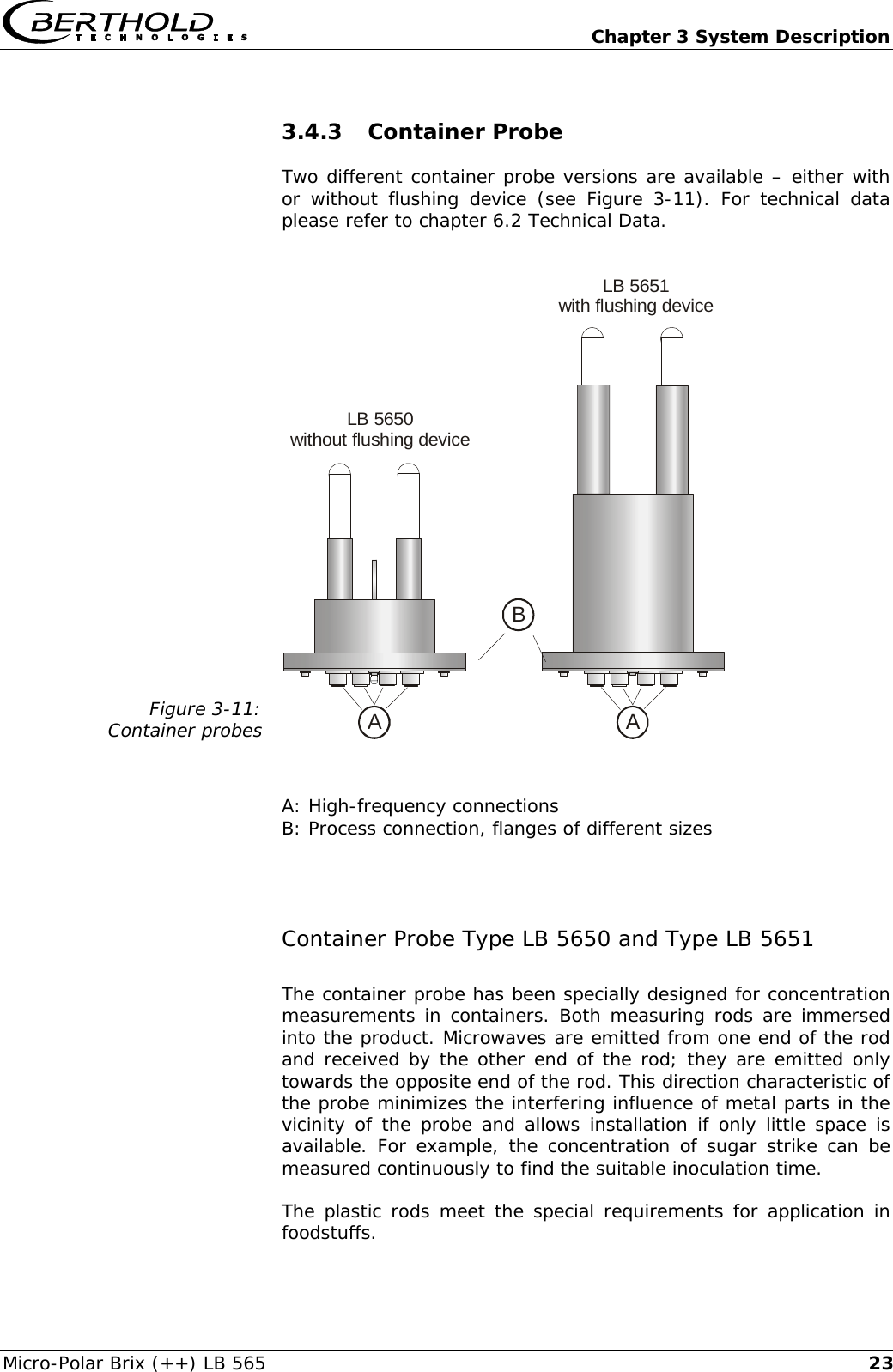
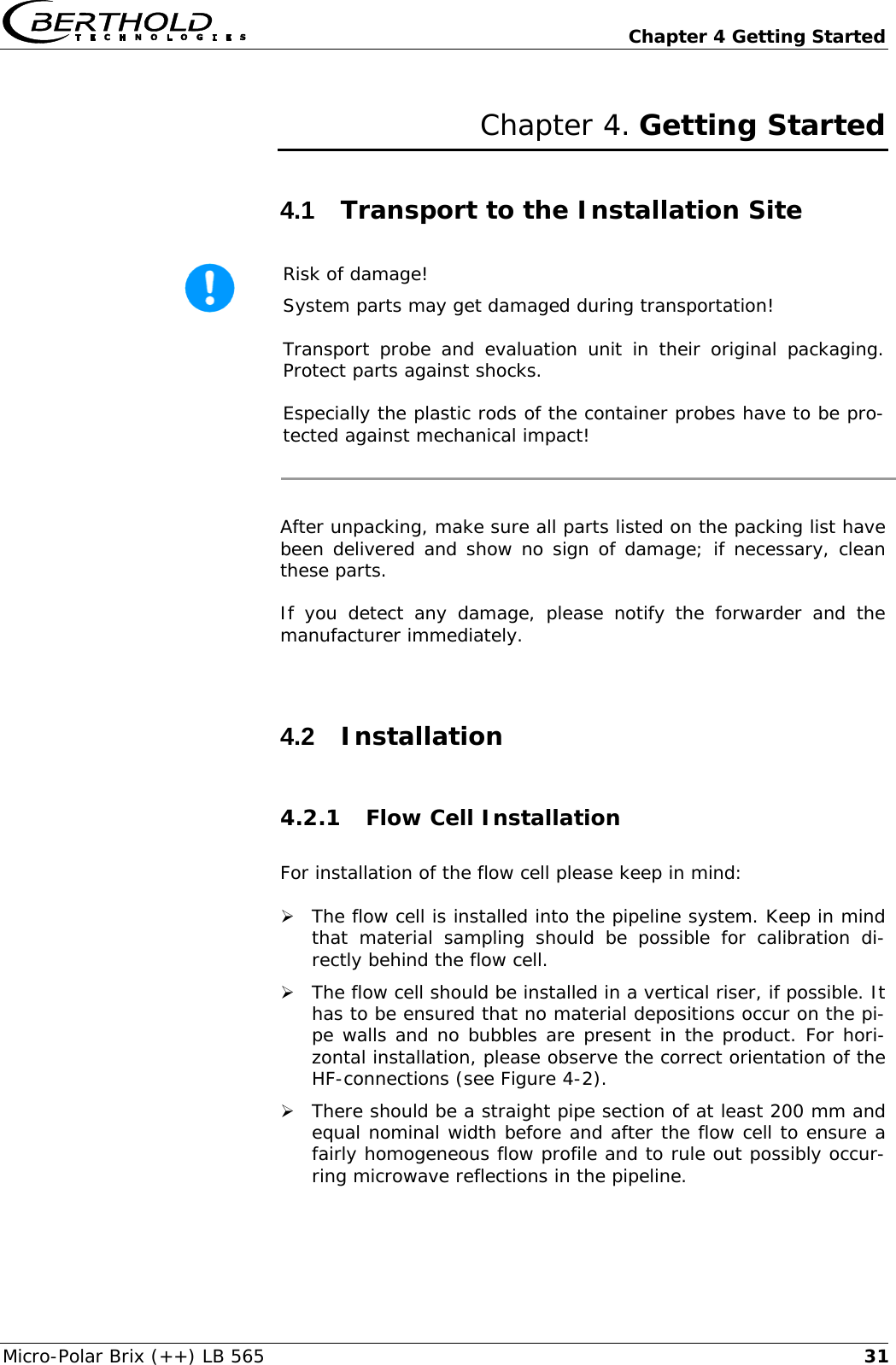
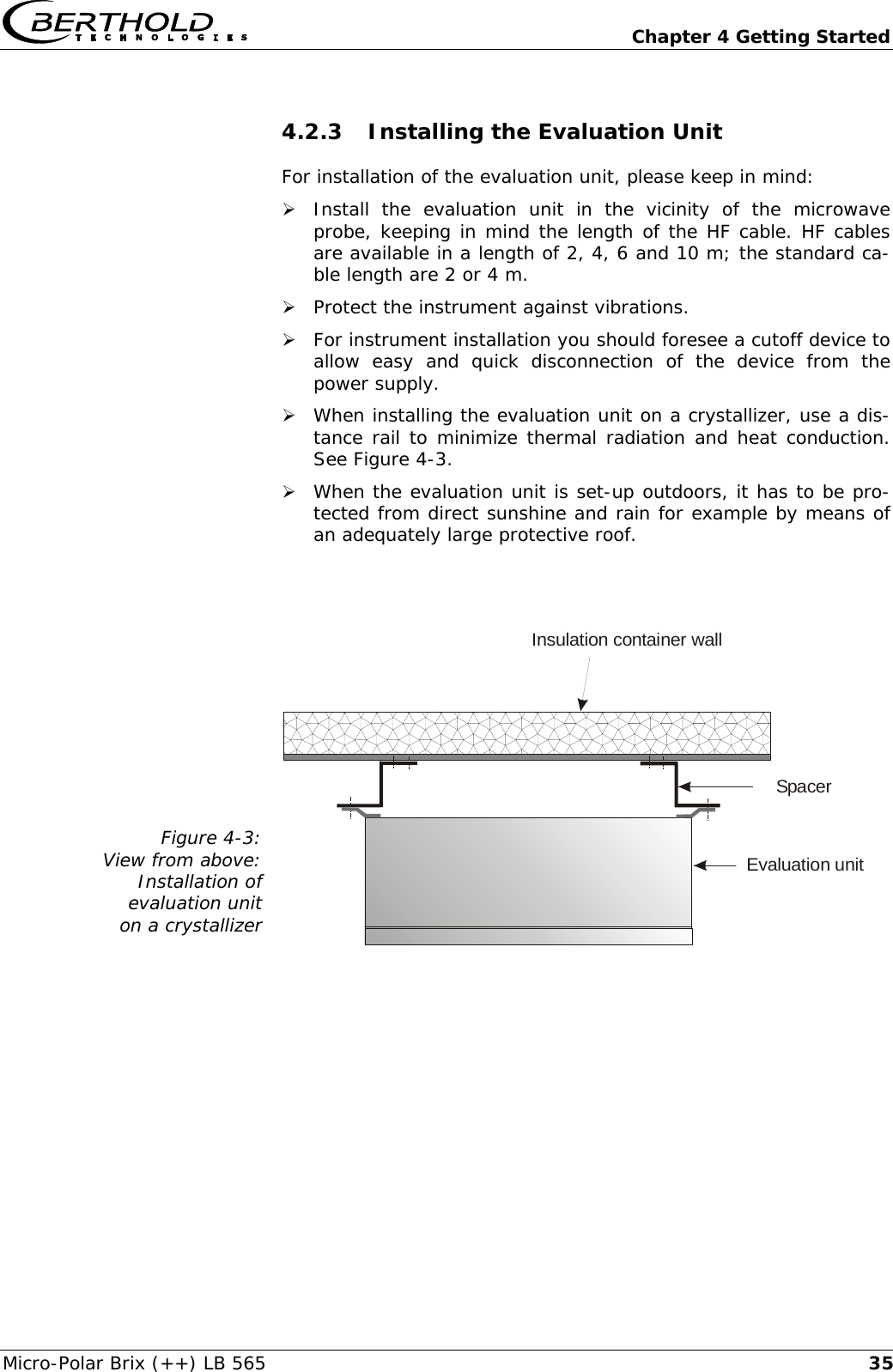
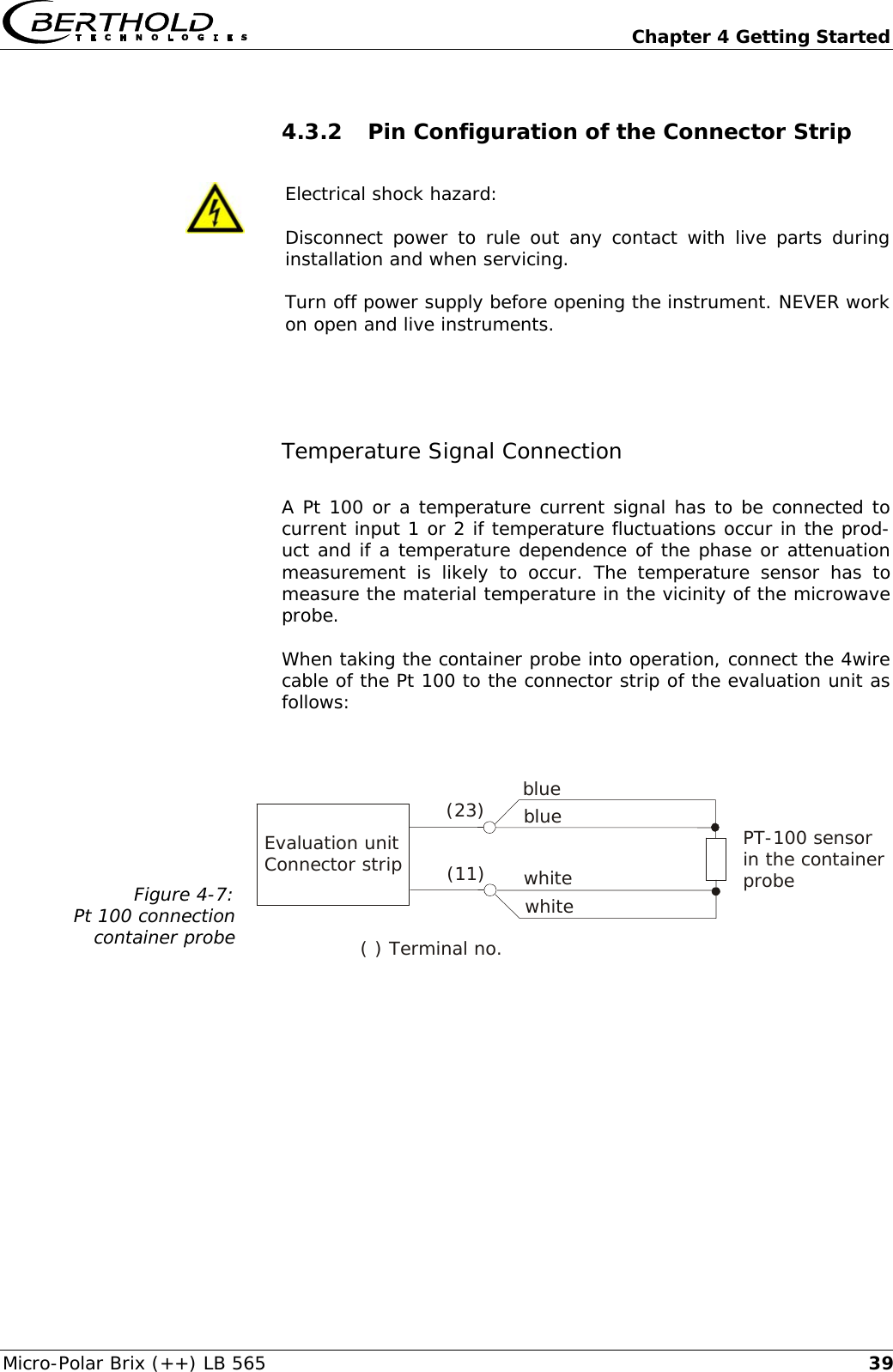
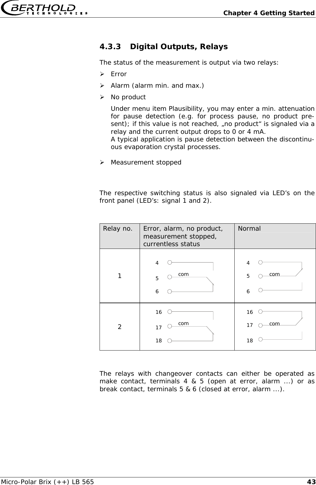
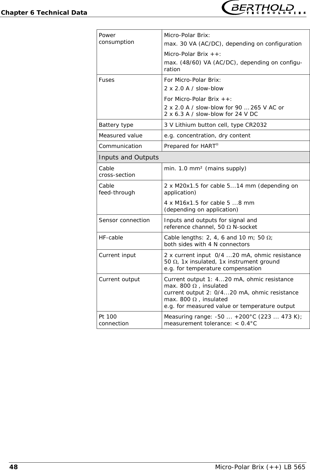
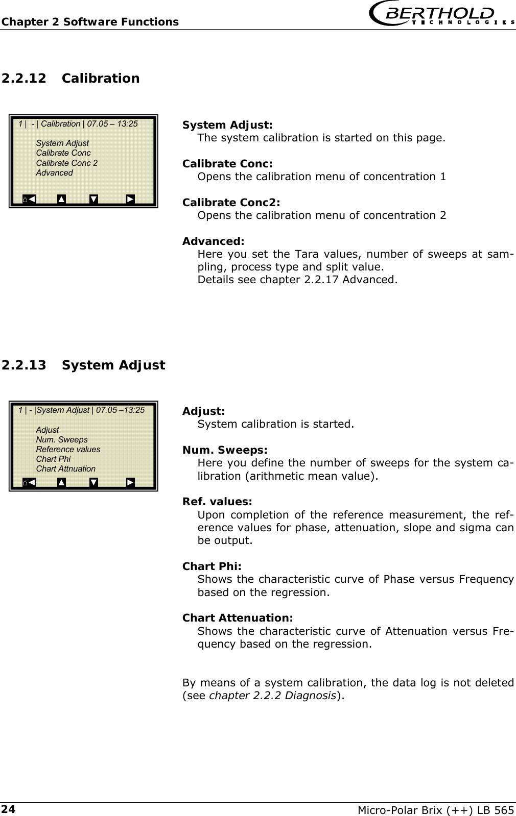
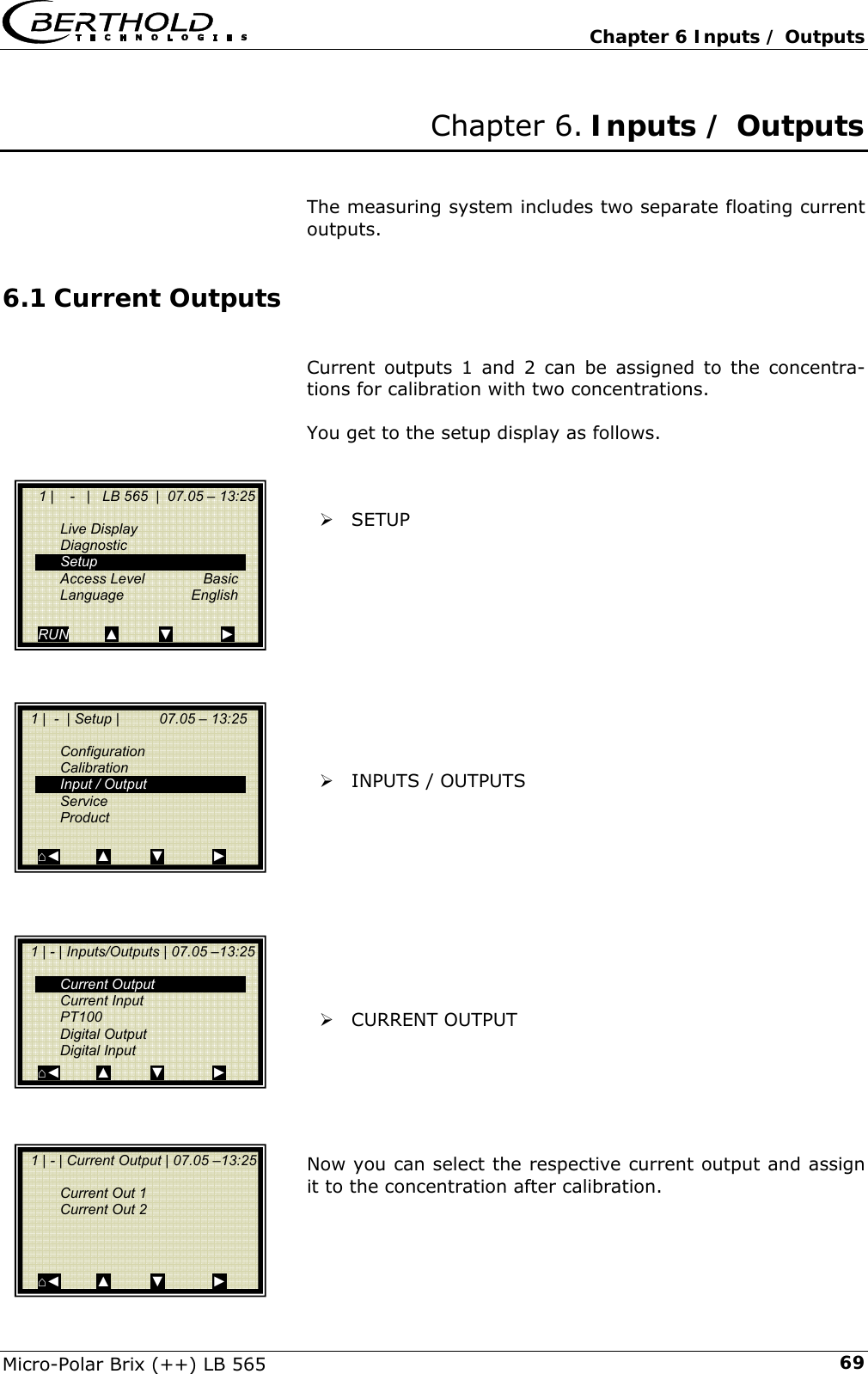
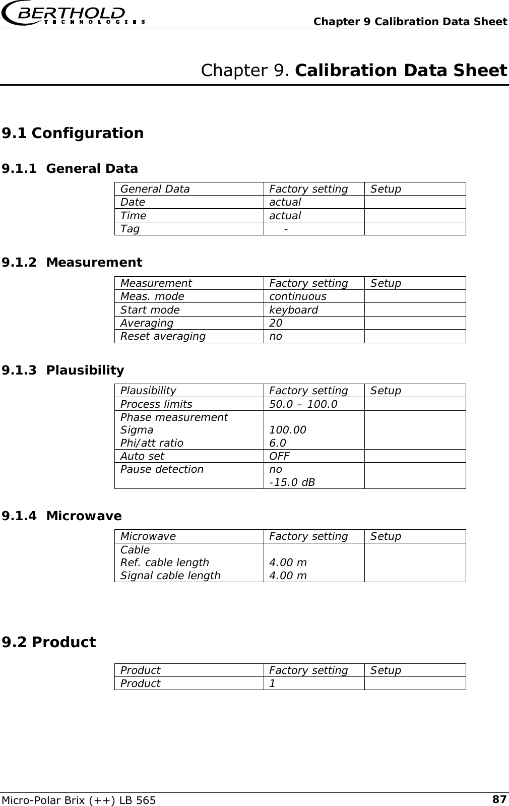
![Chapter 2 Software Functions Micro-Polar Brix (++) LB 565 222.2.11 Pause Detection Enabled Here the pause function is activated and deactivated. Con-sider the measuring conditions for using the pause detec-tion; see below. Attenuation min Input of the minimum attenuation, when falling below that value measurement goes into pause mode. Conditions and discription: The pause detection function is a software feature for pause detection between two sequential discontinuous crystallization processes. This is interesting because dur-ing the cleaning phase, the sensor indicates the lower cur-rent output value (0/4 mA). Only after restart of a crystal-lization process, does the sensor show the current dry substance content (Brix content) after product entry. Condition: pure phase calibration first order. This corre-sponds to the default adjustment of the automatical cali-bration. For example: typical signal behavior of two crystallization processes. Necessary Software Installations Enter under menu SETUP | CONFIGURATION | PLAUSIBIL-ITY | the following values: - Under PROCESS LIMITS: Min. Conc. and Max. Conc. Entry of process limits: ±5 %DS to the real process limits. Example: real process limits 70 to 90 %DS, therefore 65 to 95 %DS is entered. - Under PAUSE DETECTION: The pause detection can be activated here. Switching variable is the attenuation; if the entered minimum attenuation is fallen short of, then the evaluation unit pauses. 1 | - | Pause detection | 07.05 – 13:25 Enabled no Attenuation min -15 dB ⌂◄ ▲ ▼ ► tCurrentoutput[mA]0/4Pause20tCurrentoutput[mA]0/4Pause20](https://usermanual.wiki/Berthold-Technologies/FCC01X12/User-Guide-1100454-Page-114.png)
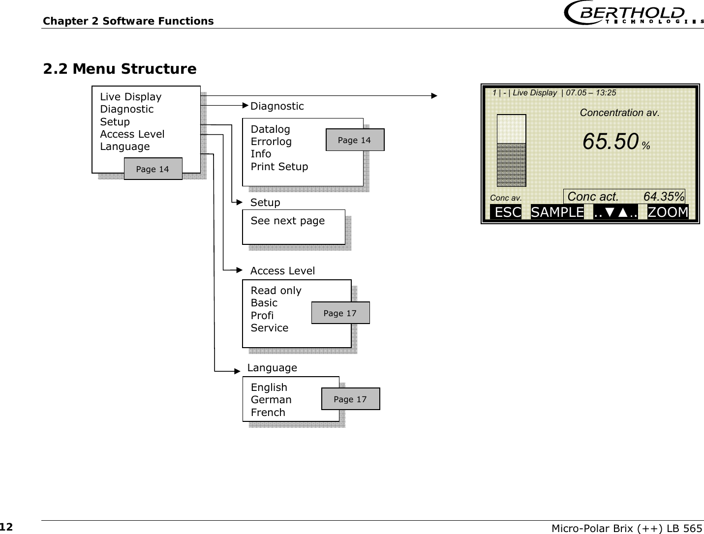
![Chapter 2 Software Functions Micro-Polar Brix (++) LB 565 23Adjust these settings if applicable according to the condi-tions of „Quitting the pause mode” (see below). Determination of the min. attenuation as a switching variable: For this, the attenuation process must be observed up to the end of a crystalliza-tion process including cleaning phase. In addition, you can take the data log (see chapter 2.2.2 diagnosis) for assistance. For example, typical attenuation process: D1 = smallest attenuation value in the product D2 = Attenuation value for an empty vessel D (min) = Switching variable = average attenuation be-tween D1 and D2 Typical values (Sugar beet): D1: -15 to -10 dB D2: -25 to -20 dB D (min): -20 to -15 dB Quitting the pause mode (change to measuring mode): Two conditions have to be met before changing the mode: 1. The attenuation has to be higher than the attenua-tion threshold. 2. The recent concentration (Conc act.) has to be in the following range: - Conc act.> min. process limit - Conc act.< min. process limit – A1·Faktor·146 A1: Calibration coefficient of the phase Factor: From tuning (Default =1; see chapter 2.2.13 Calibr. Concentration). Process limit: See menu PLAUSIBILITY tAttenuation [dB]0PauseD1D2tAttenuation [dB]0PauseD1D2](https://usermanual.wiki/Berthold-Technologies/FCC01X12/User-Guide-1100454-Page-115.png)
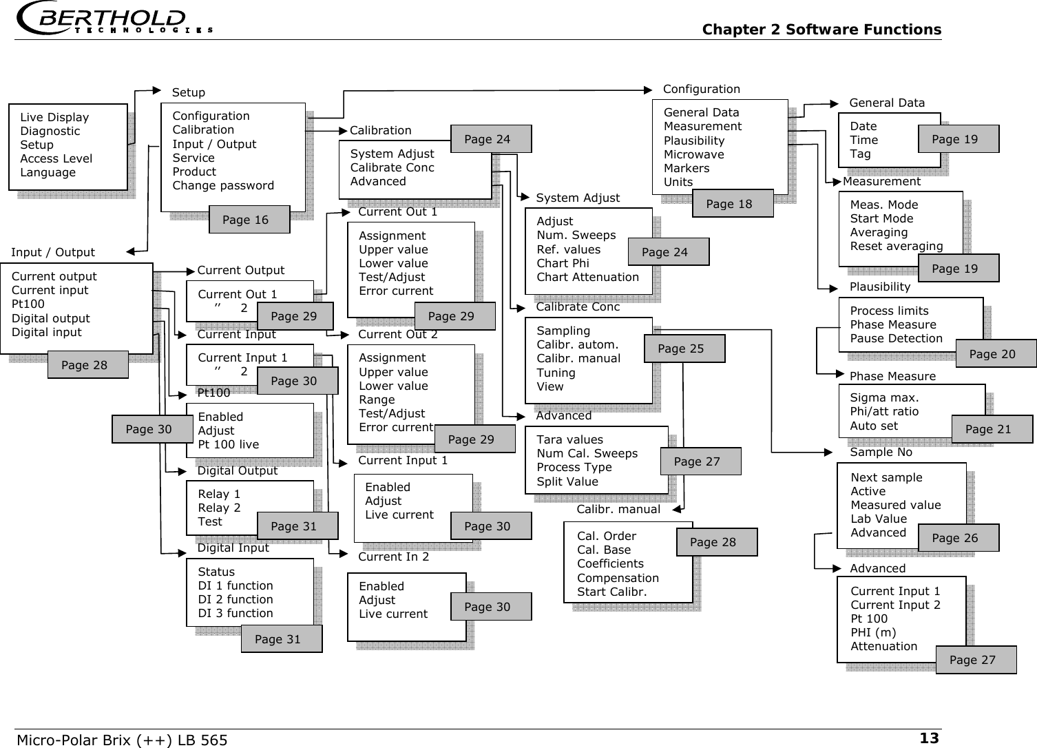
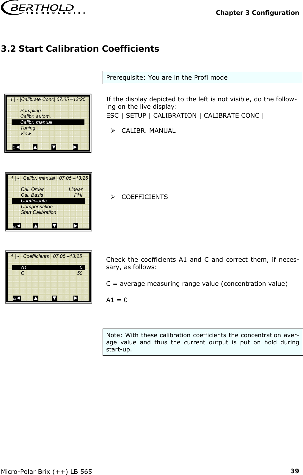
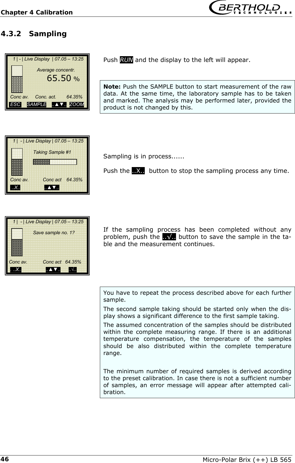
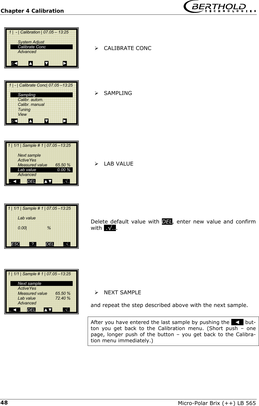
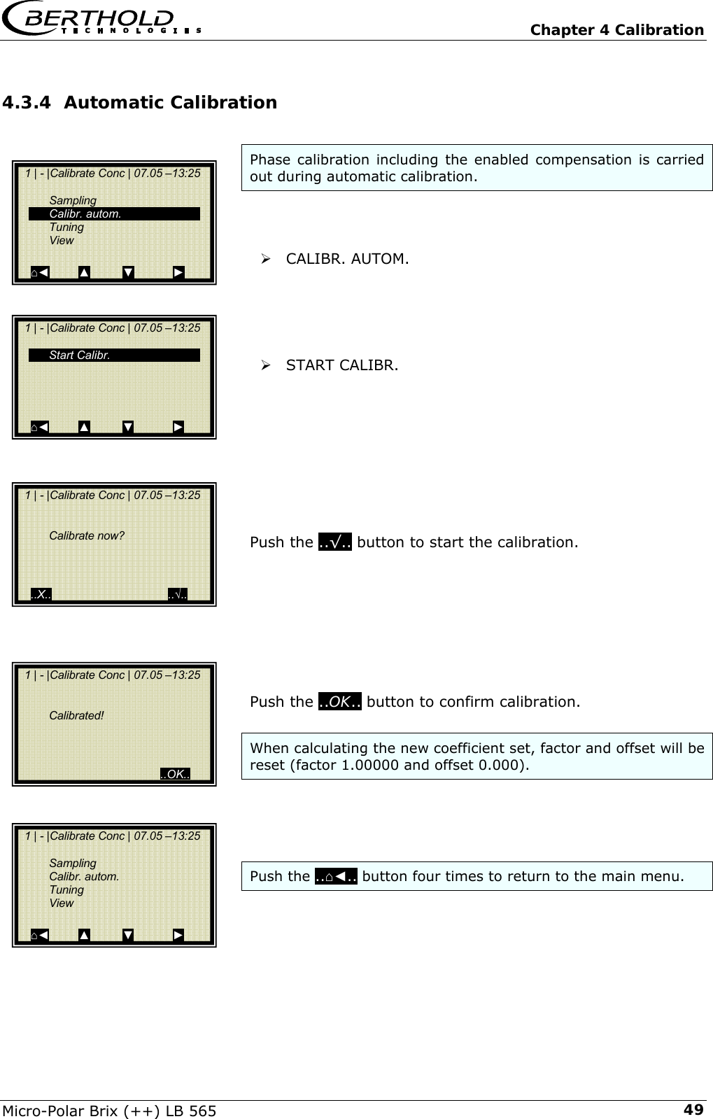
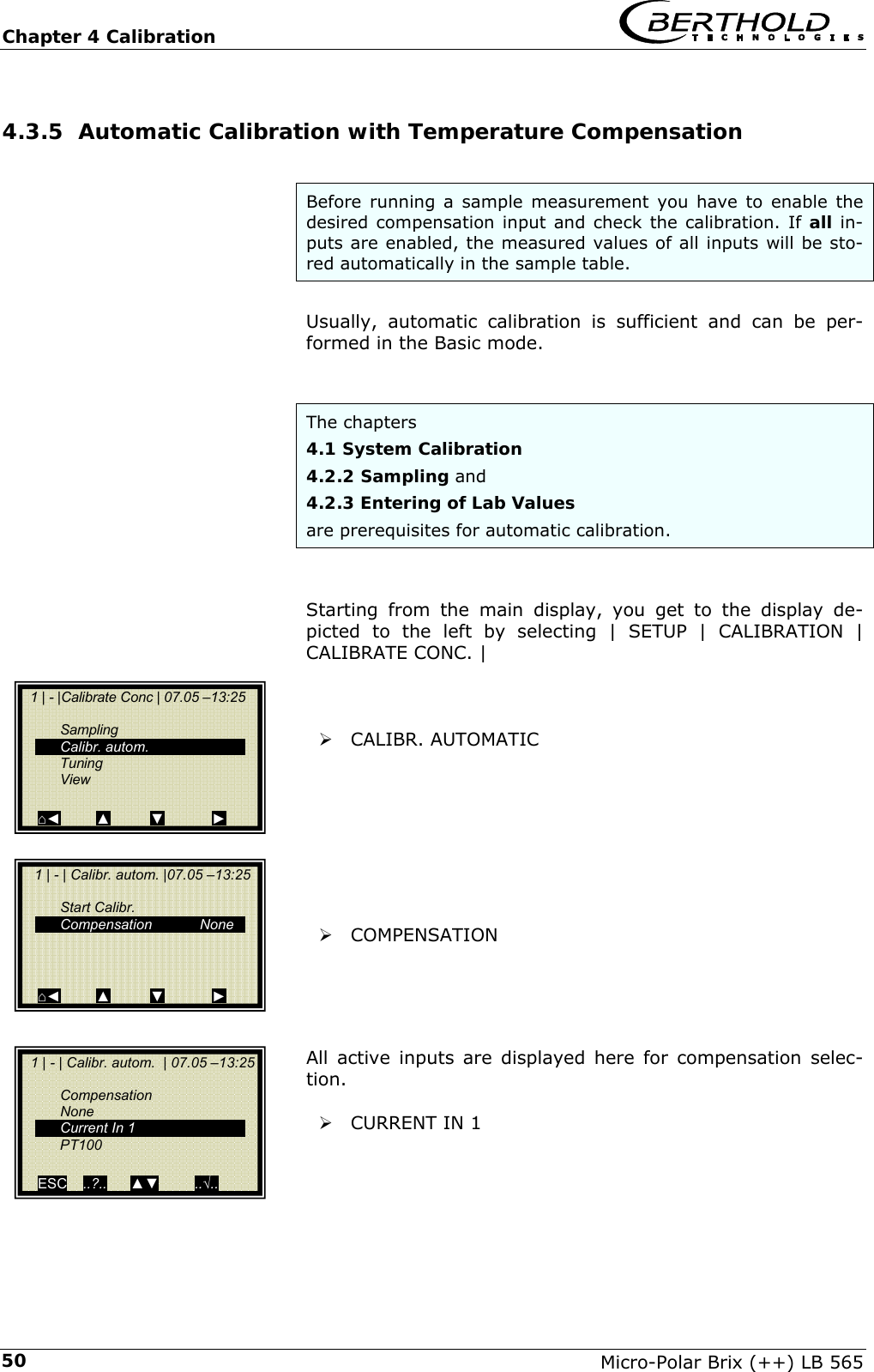
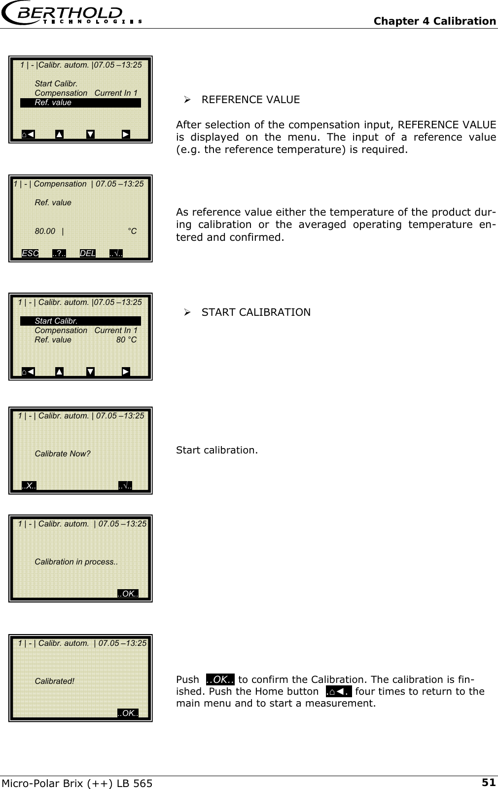
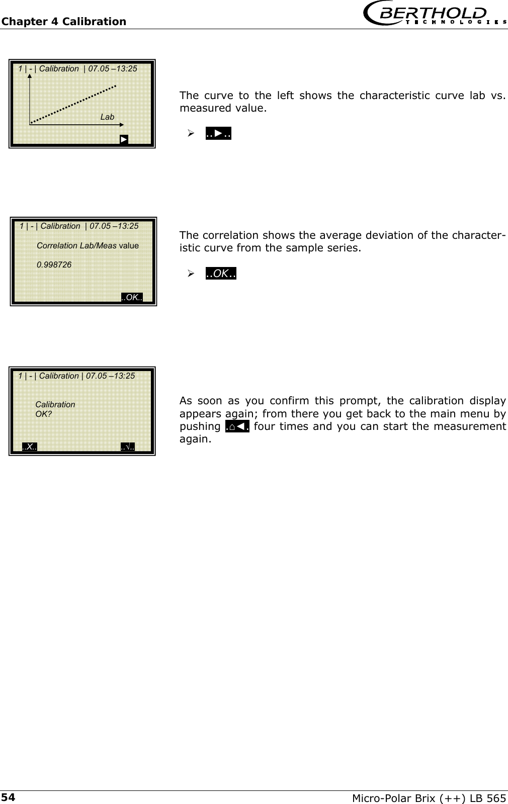
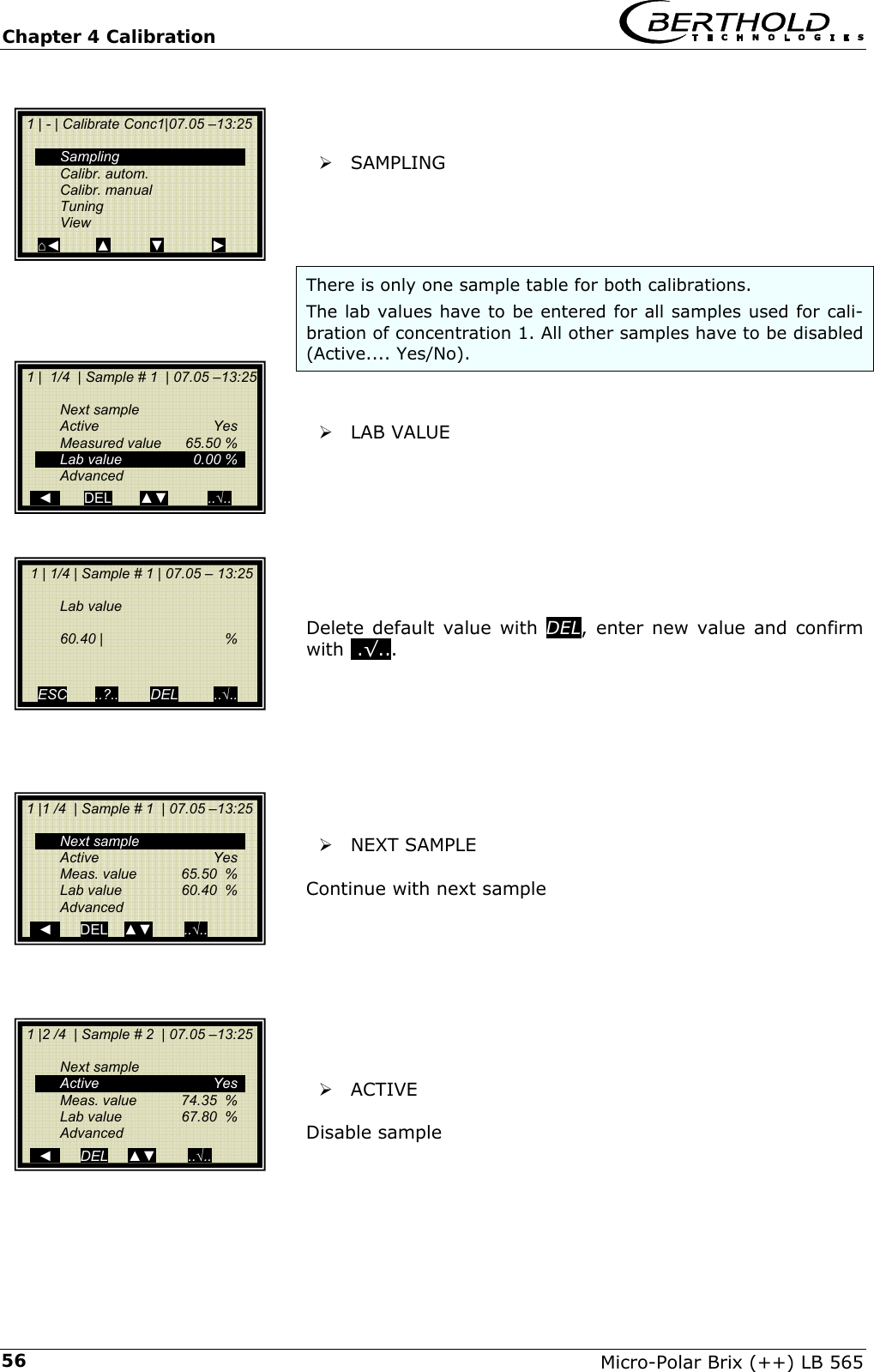
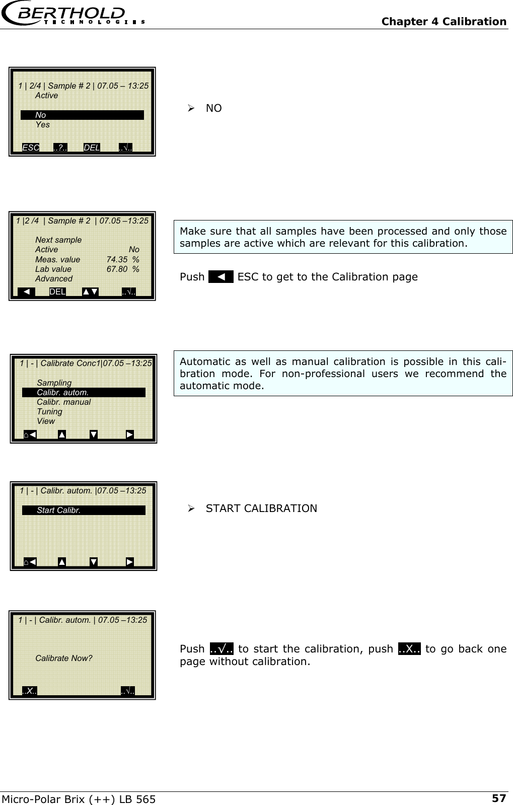
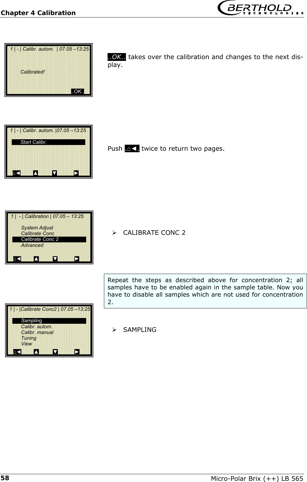
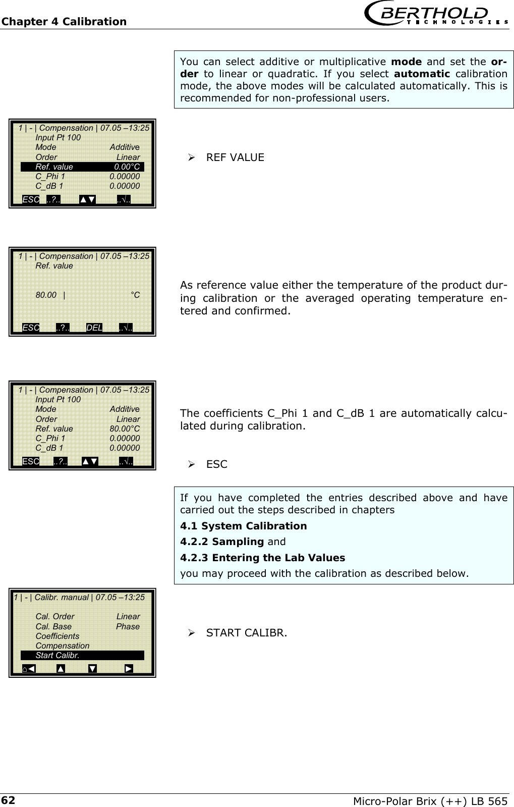
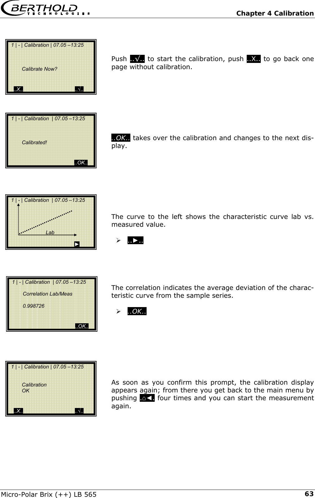
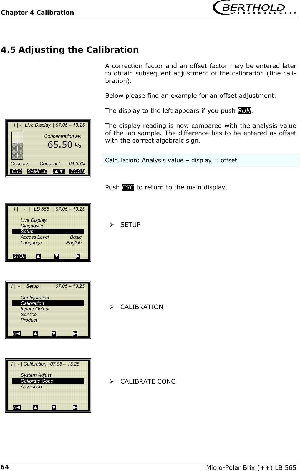
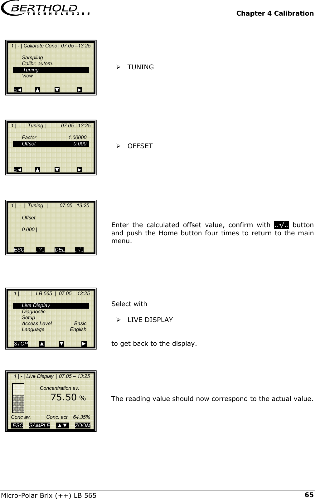
![Chapter 2 Software Functions Micro-Polar Brix (++) LB 565 252.2.14 Calibrate Concentration Sampling: Shows all measured samples. Calibr. autom.: Calibration can be started after measurement of two sam-ples and input of the respective laboratory values. More-over, compensation can be enabled if the following pre-requisites have been fulfilled: 1. The respective analog input has been enabled (Pt100 or current input 1 / 2). 2. Sampling has been carried out using the previously set up compensation input. 3. The reference value has been entered on the menu COMPENSATION. The reference value is either the current product temperature at system adjustment or the average product temperature. There are at least three samples needed for temperature compensation, otherwise the calibration error “Keeping old coefficients” appears at the evaluation unit. Basis of automatic calibration (fixed setting): • Linear phase calibration • Compensation: additive and linear Calibr. manual: Here you can choose the calibration order [lin-ear/quadratic], the basis [phase/attenuation or both] and compensation temperature. Tuning: Subsequent correction of the reading is possible by enter-ing a factor and an offset. Calculation is carried out according to the following for-mula: offsetfactordisplaydisplayCorrected +⋅= View: Presentation of calibration curve, display of correlation and coefficients. 1 | - |Calibrate Conc| 07.05 –13:25 Sampling Calibr. autom. Calibr. manual Tuning View ⌂◄ ▲ ▼ ►](https://usermanual.wiki/Berthold-Technologies/FCC01X12/User-Guide-1100454-Page-117.png)
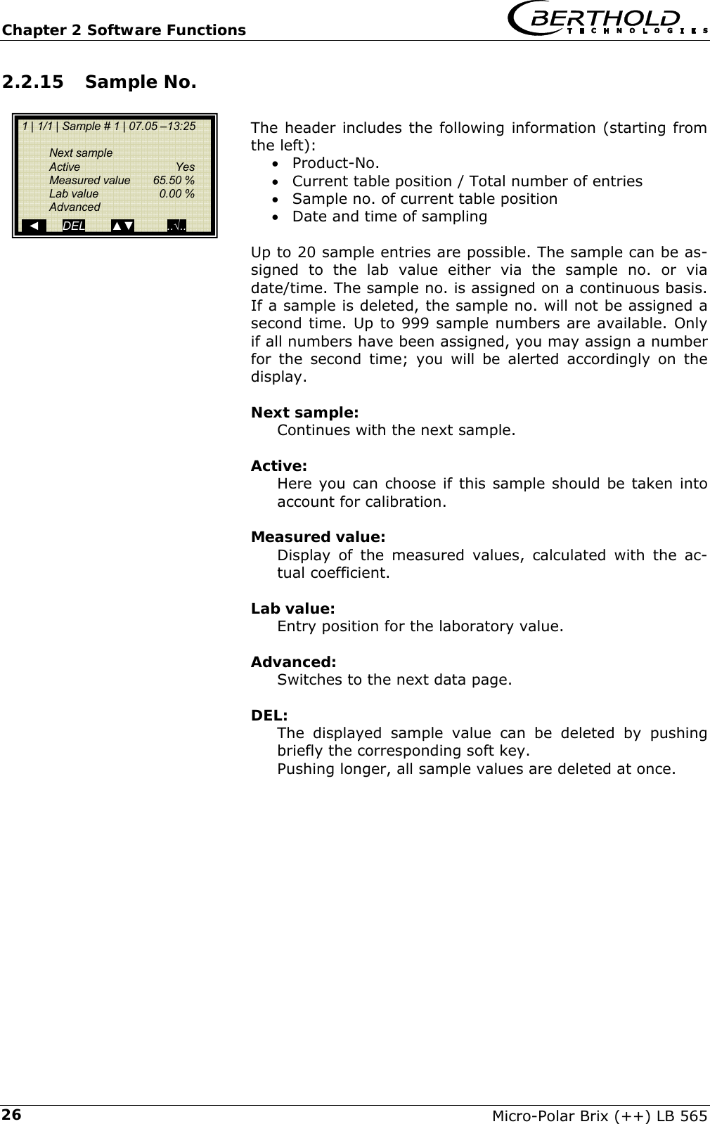
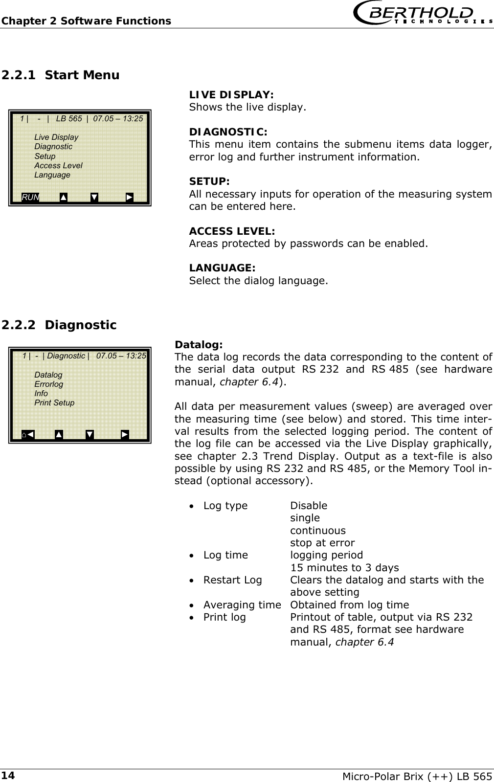
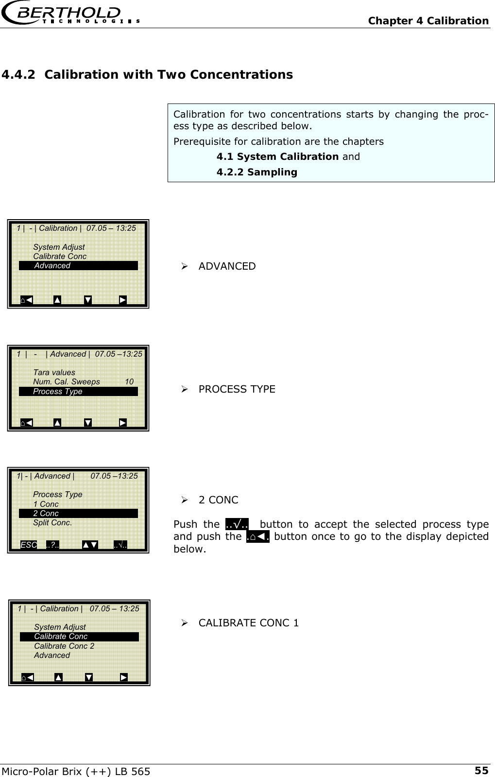
![Chapter 2 Software Functions Micro-Polar Brix (++) LB 565 272.2.16 Sample Data (expanded) Current In 1: Editable display of the first compensation input. Current In 2: Editable display of the second compensation input. Pt 100: Editable display of the Pt 100 input. PHI (m): Not editable display of the measured phase. Attenuation: Not editable display of the measured attenuation. 2.2.17 Advanced Settings Tara Values: Input option of Tara values for phase and attenuation. The Tara values are attributed to the phase or the attenuation before calibration. The calculation is the following: Phase = Phasemeas - Phase Tara Attenuation = Attunationmeas - AttenuationTara This function is not needed for the determination of dry substance, brix or density in sugar solution. Number of Calibration Sweeps: Freely adjustable number of sweeps over which a calibra-tion point (in the course of automatic sample measure-ment) will be averaged. Process Type: Select the operation mode: • one concentration [1 measuring range] • two concentrations [2 measuring ranges] • split concentration [1 measuring range with switching point (split value) for coefficient switchover]. Split Value: Setting of the switching point on a value basis. 1 | - | Advanced | 07.05 –13:25 Tara values Num. Cal. Sweeps Process type Split Value ⌂◄ ▲ ▼ ► 1 | 1/1 | Sample # 1 | 07.05 –13:25 Current In 1 Current In 2 PT100 PHI (m) Attenuation ◄ DEL ▲▼ ..√..](https://usermanual.wiki/Berthold-Technologies/FCC01X12/User-Guide-1100454-Page-119.png)
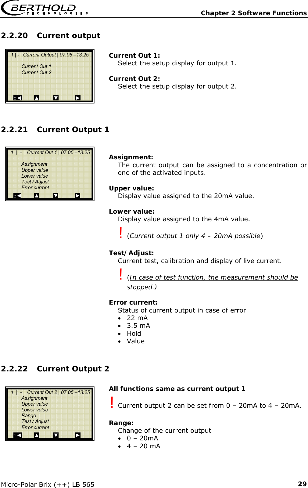
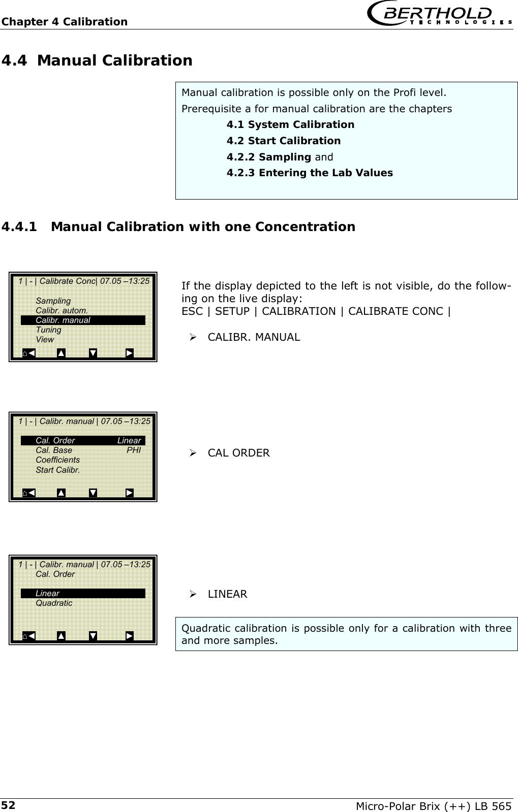
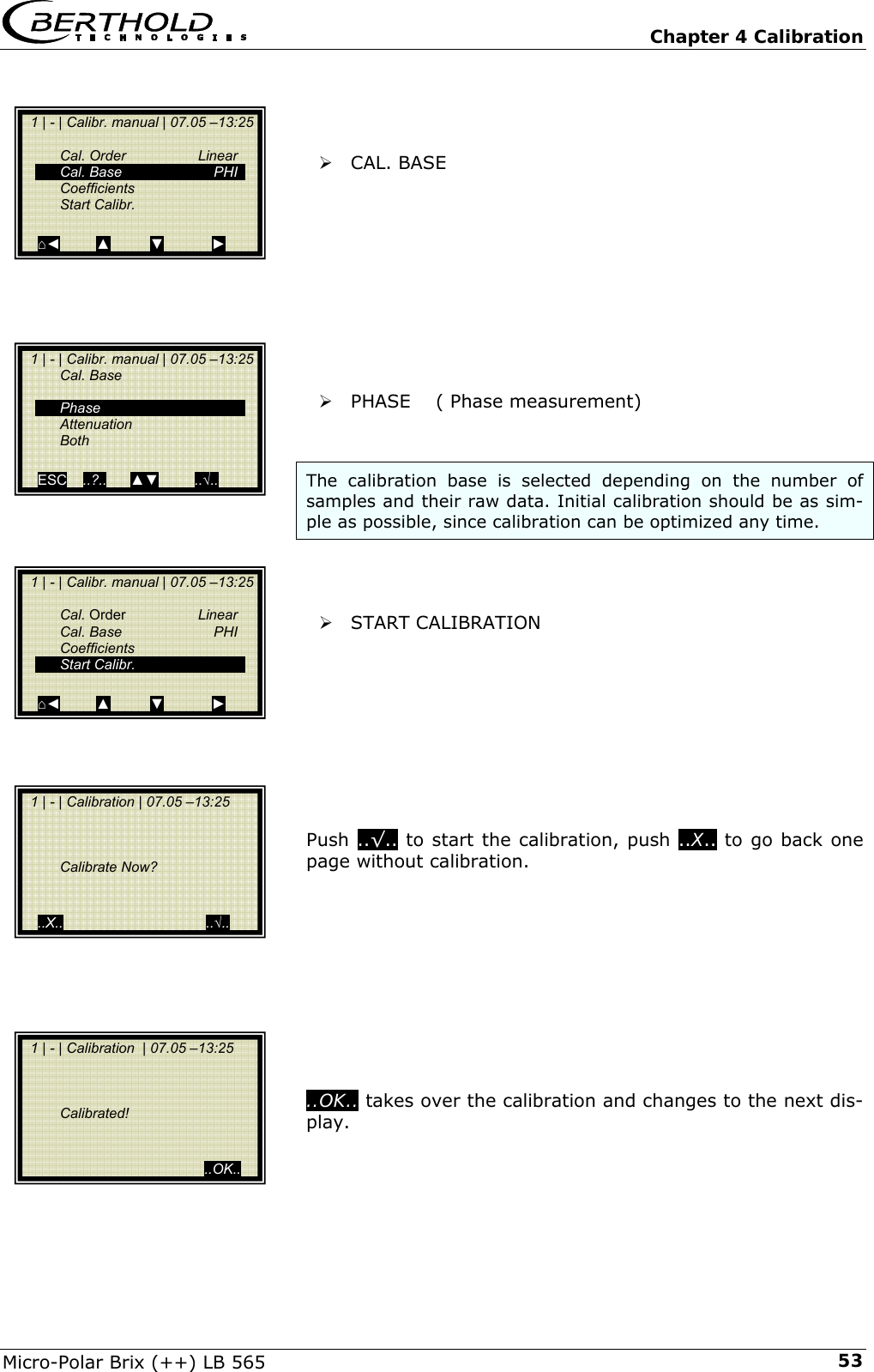
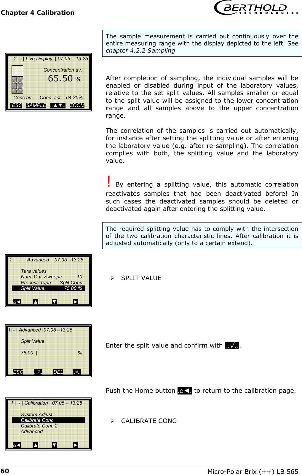
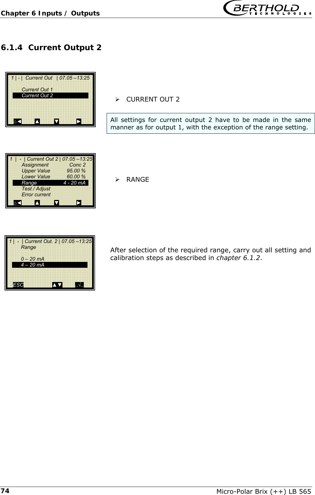
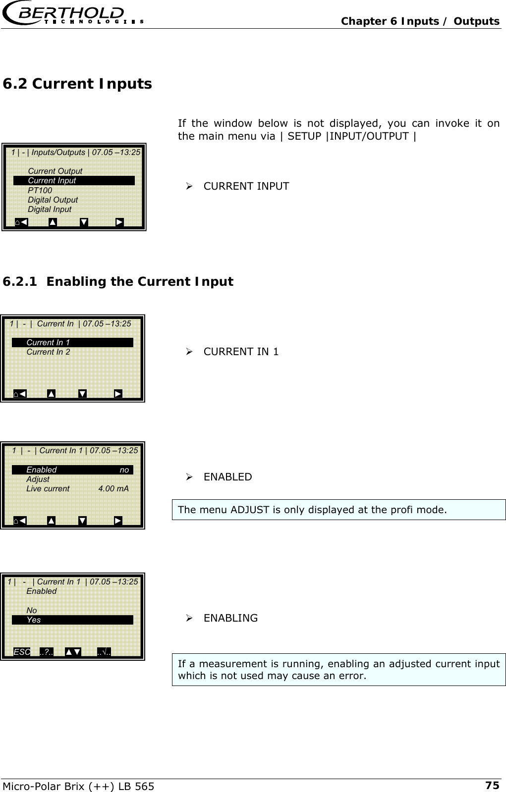
![Chapter 2 Software Functions Micro-Polar Brix (++) LB 565 282.2.18 Calibr. manual Cal. Order: Here you define the calibration order [linear / quadratic] Cal. Base: The following parameters can be set: • Phase • Attenuation • Phase and attenuation Coefficients: Here you can edit all coefficients for phase and attenua-tion. Compensation: If at least one analog input is active, you may assign the compensation and set the compensation parameters. Start Calibr.: Starts the calibration using the parameters you have set earlier. 2.2.19 Input / Output Current Output: Both outputs can be adjusted, assigned and set up on the selected level. Current Input: Activation level of current input, calibration and display of the live current signal. Pt 100: Here you can enable and adjust a connected Pt 100. Dis-play of the actual temperature signal. Digital Output: Allocation of relays 1 and 2 and test function. Digital Input: Status control and assignment of the digital inputs. 1 | - | Calibr. manual | 07.05 –13:25 Cal. Order Cal. Base Coefficients Compensation Start Calibr. ⌂◄ ▲ ▼ ► 1 | - | Inputs/Outputs | 07.05 –13:25 Current Output Current Input PT100 Digital Output Digital Input ⌂◄ ▲ ▼ ►](https://usermanual.wiki/Berthold-Technologies/FCC01X12/User-Guide-1100454-Page-120.png)
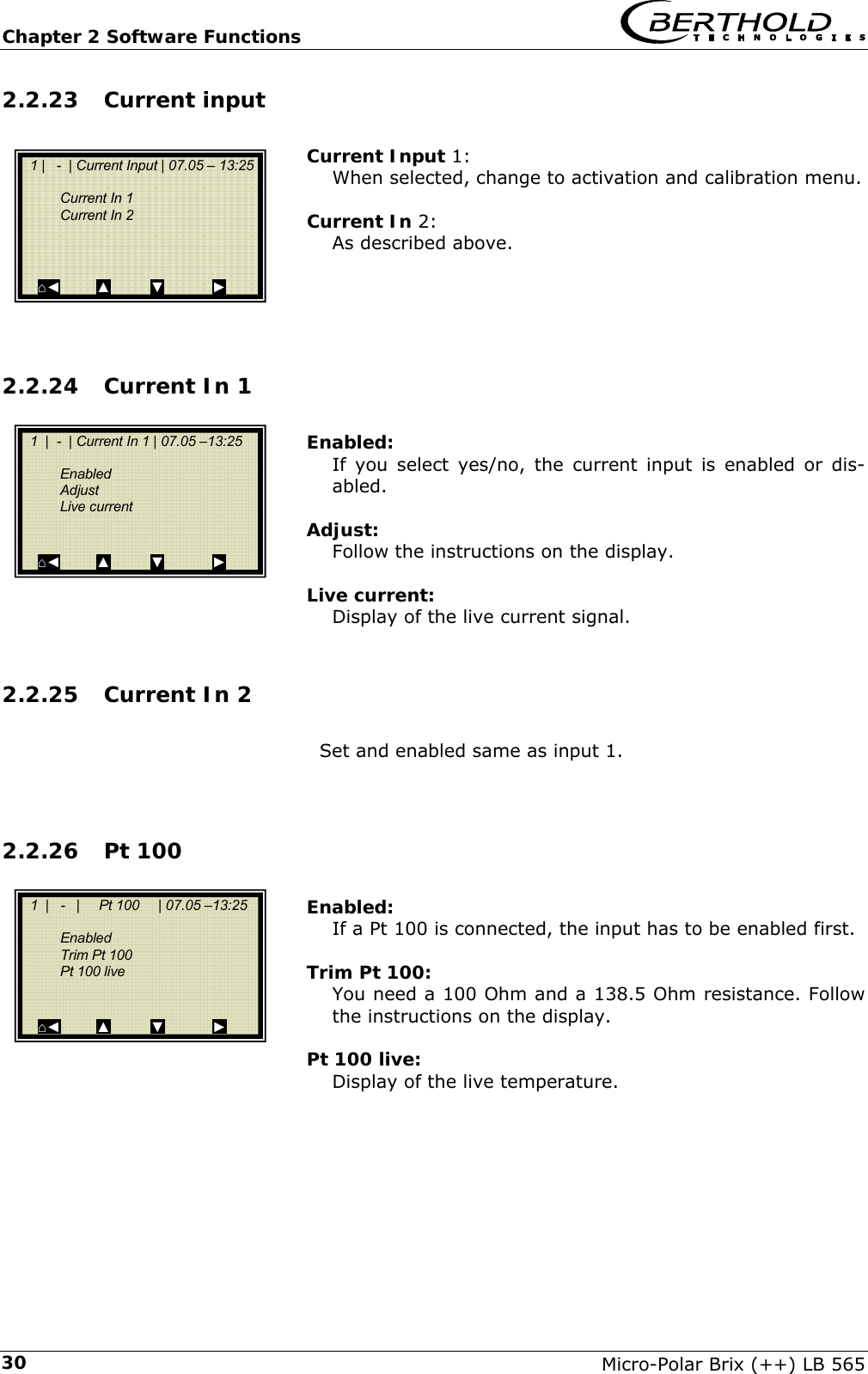
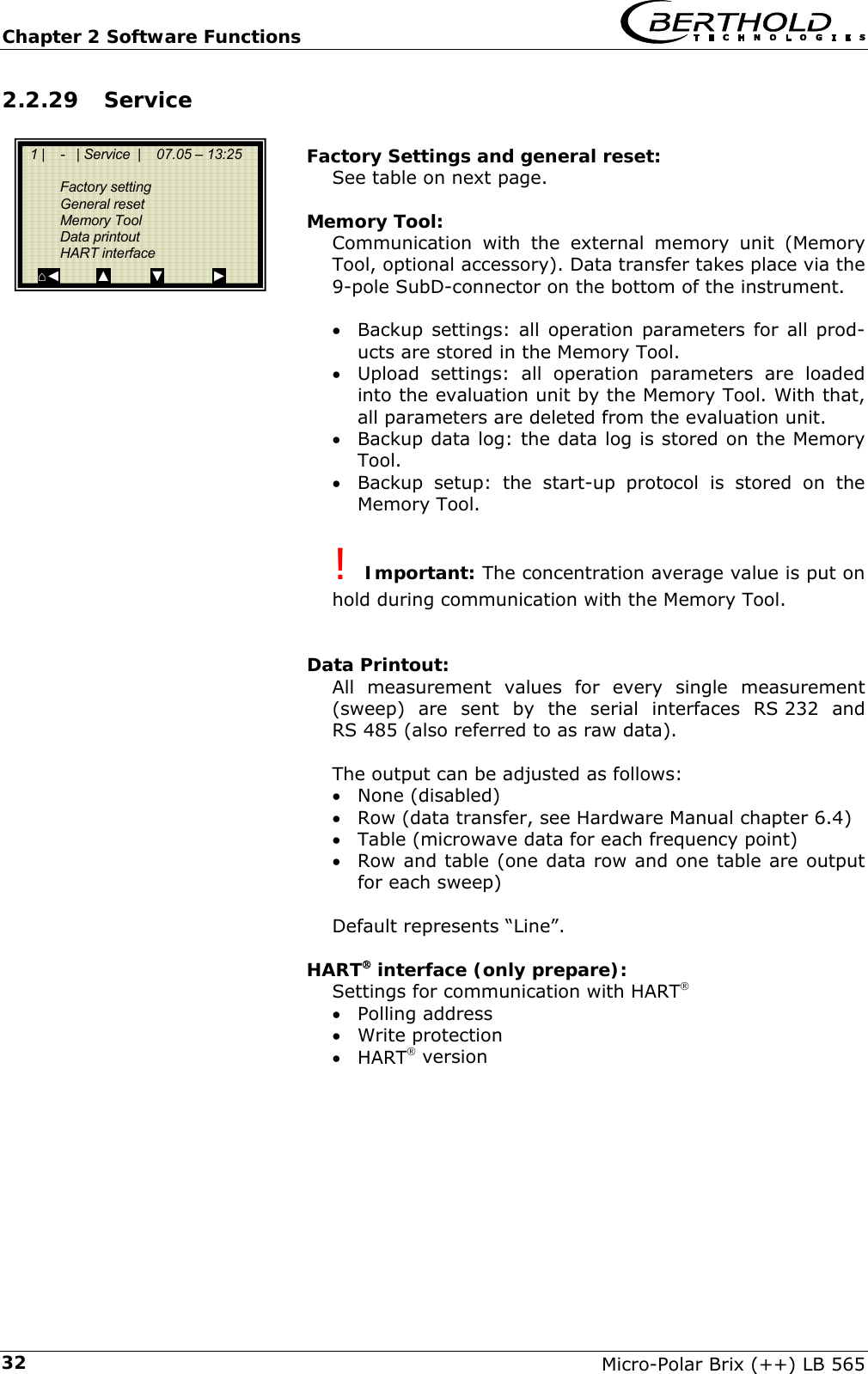
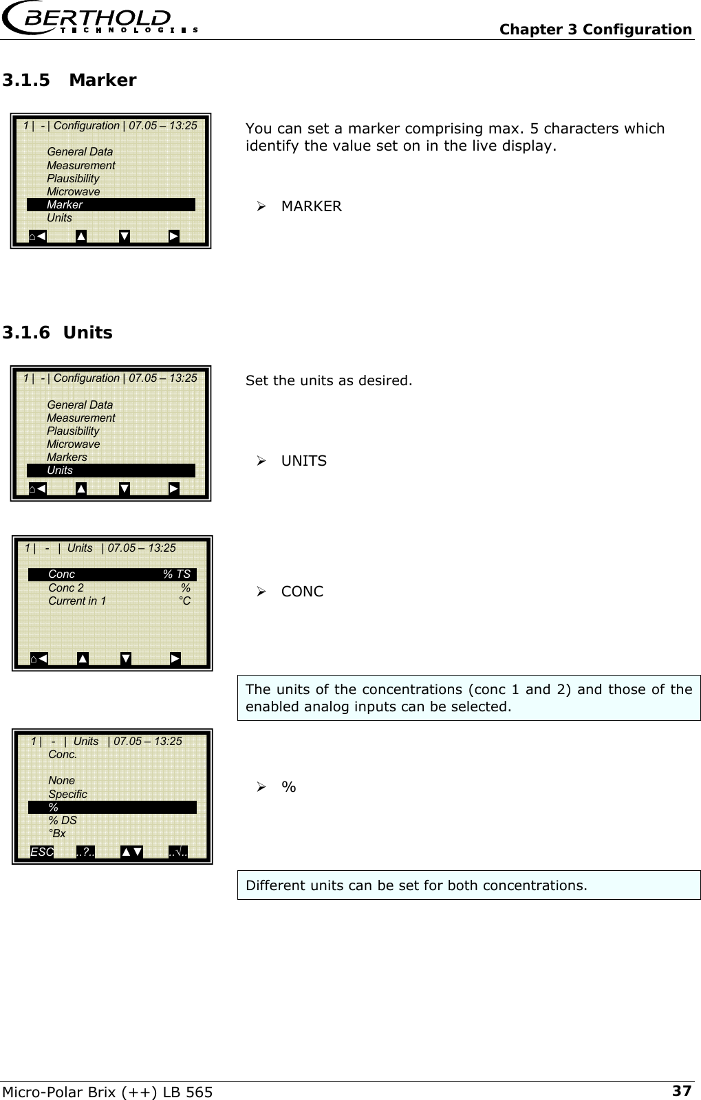
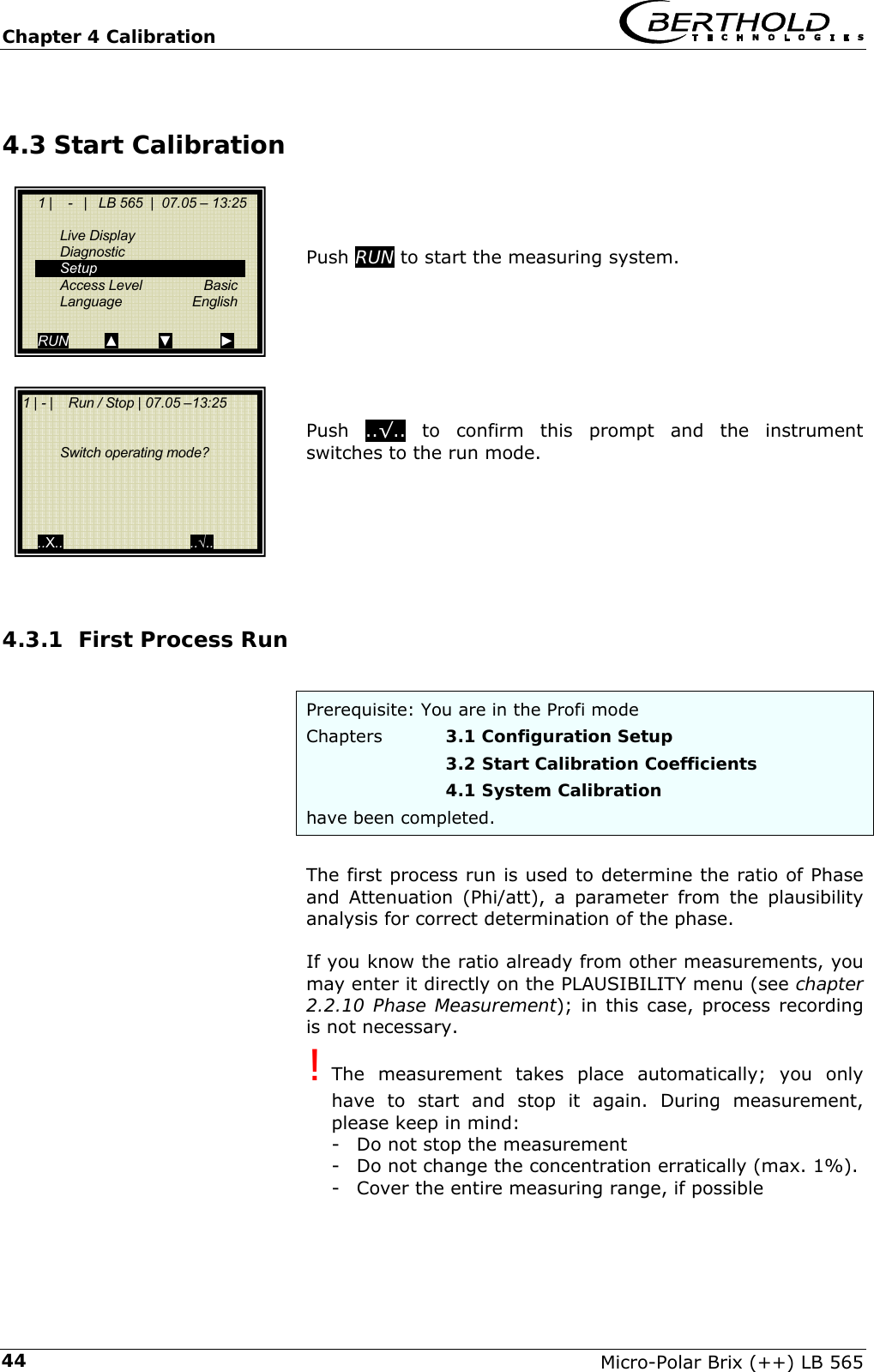
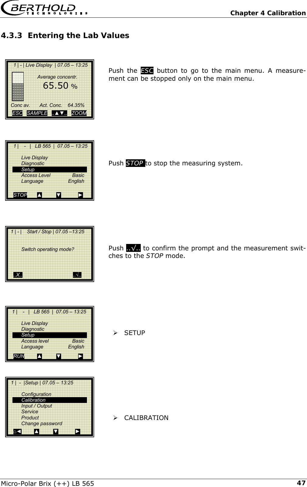
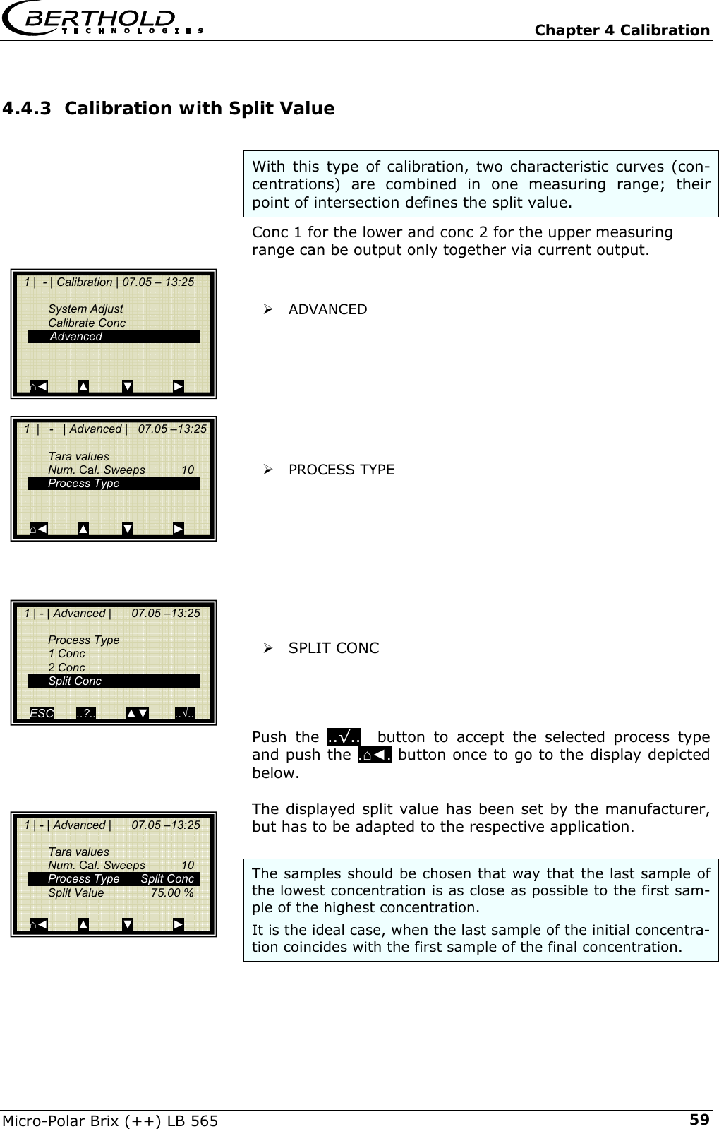
![Chapter 3 Configuration Micro-Polar Brix (++) LB 565 35Chapter 3. Configuration Before carrying out any calibration work, you should check the configuration setup of the measuring system and change it, if necessary. 3.1 Configuration Setup ¾ CONFIGURATION 3.1.1 General Data ¾ GENERAL DATA Example: Select the respective entry, edit and store it. ¾ DATE Push DEL to delete the entry and then enter the new date. Push..√.. to confirm and store the changed date. ! The colon for the time input (e.g. 13:25) is invoked by pushing the button [ . ]. 1 | - | Setup | 07.05 – 13:25 Configuration Calibration Input / Output Service Product Change password ⌂◄ ▲ ▼ ► 1 | - | Configuration l | 07.05 – 13:25 General Data Measurement Plausibility Microwave Marker Units ⌂◄ ▲ ▼ ► 1 | - | General Datal | 07.05 – 13:25 Date 07.05.2004 Time 13:25 Tag App.1 ⌂◄ ▲ ▼ ► 1 | - | General Data | 07.05 – 13:25 Date 07.05.2004 | ESC ..?.. DEL ..√..](https://usermanual.wiki/Berthold-Technologies/FCC01X12/User-Guide-1100454-Page-127.png)
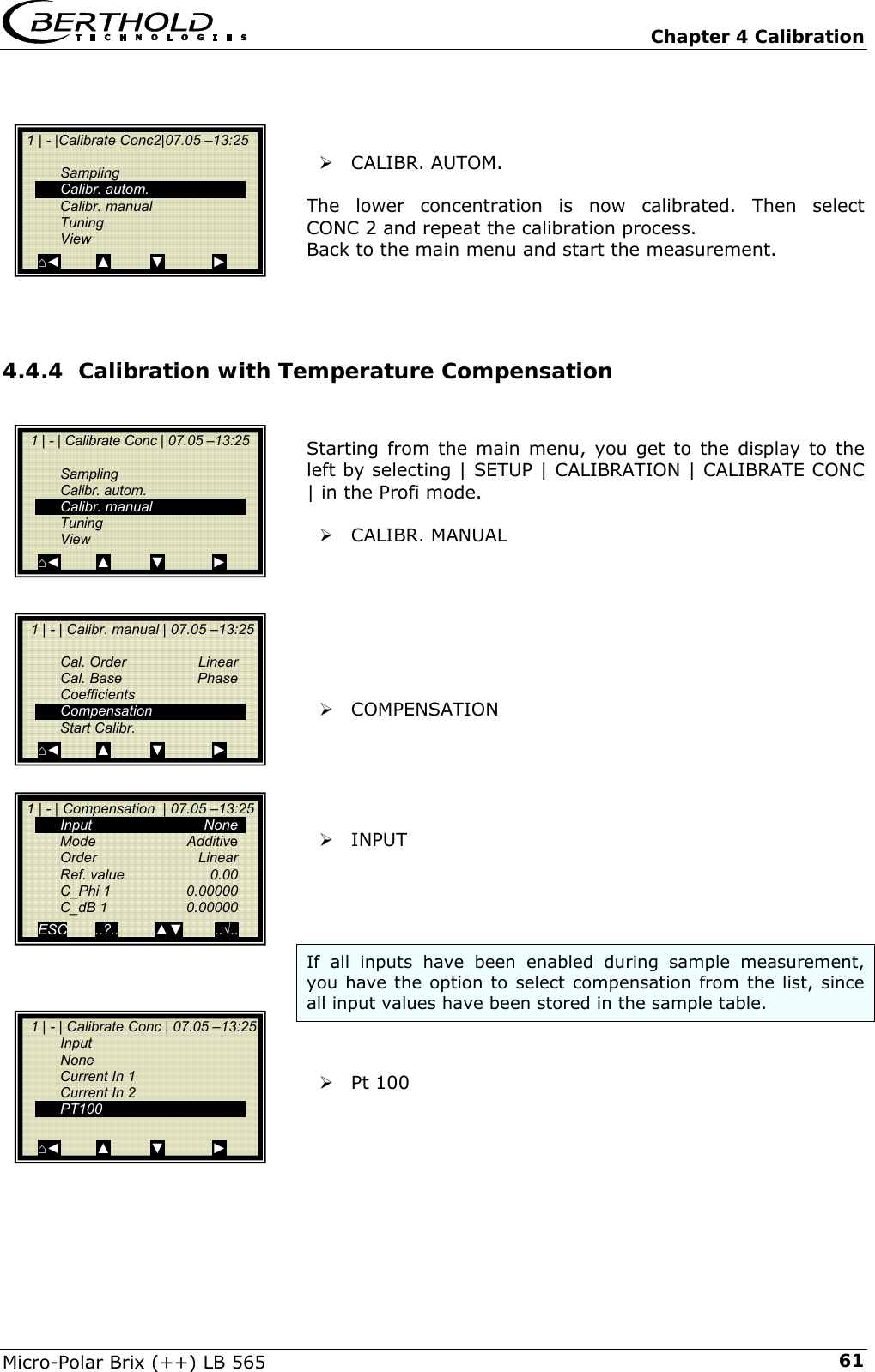
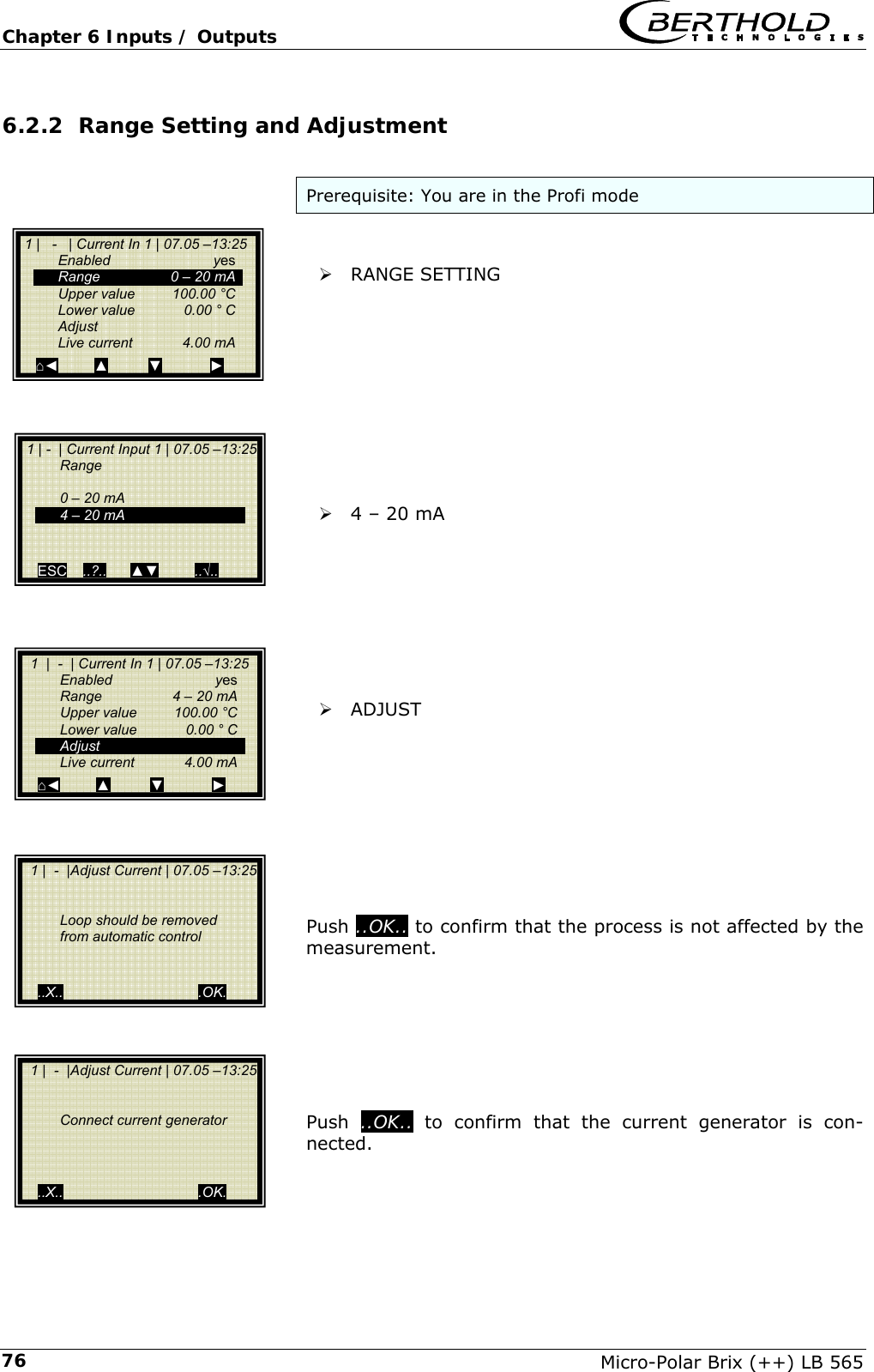
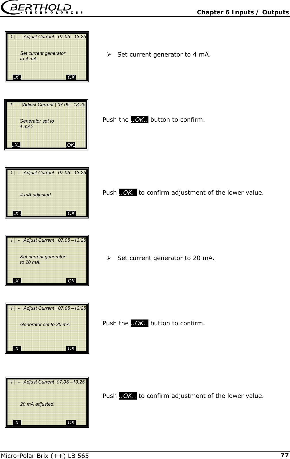
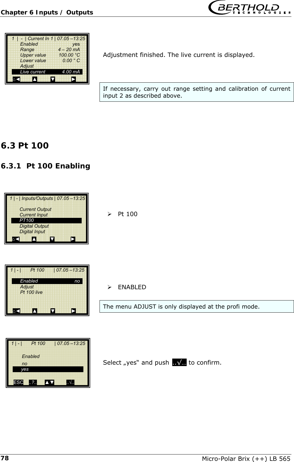
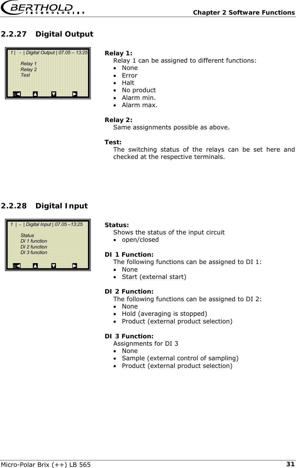
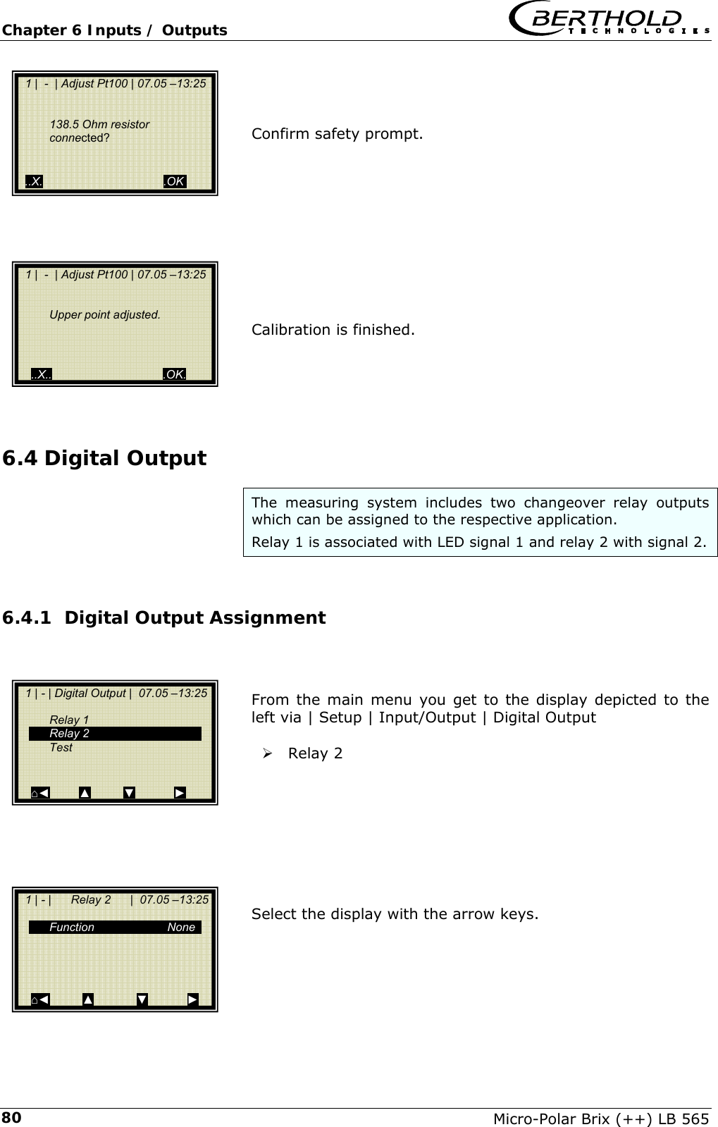
![Chapter 6 Inputs / Outputs Micro-Polar Brix (++) LB 565 796.3.2 Pt 100 Calibration Prerequisite: You are in the Profi mode ¾ ADJUST ..OK.. Connect 100 Ohm resistor to Pt100 terminals [11] [23]. Confirm once more with ..OK... Adjustment of lower point finished. After connection of the resistor, confirm with ..OK... 1 | - | Pt 100 | 07.05 –13:25 Enabled yes Adjust Pt 100 Live ⌂◄ ▲ ▼ ► 1 | - | Adjust Pt100 | 07.05 –13:25 Connect 100 Ohm resistor to Pt100 terminals. (for 0°C/31.4°F adjustment) ..X.. .OK. 1 | - | Adjust Pt100 | 07.05 –13:25 100 Ohm resistor connected? ..X.. .OK. 1 | - | Adjust Pt100 | 07.05 –13:25 Lower point adjusted. ..X.. .OK. 1 | - | Adjust Pt100 | 07.05 –13:25 Connect 138.5 Ohm resistor to Pt100 terminals. (for 100°C/211.4°F adjustment) ..X.. .OK.](https://usermanual.wiki/Berthold-Technologies/FCC01X12/User-Guide-1100454-Page-171.png)
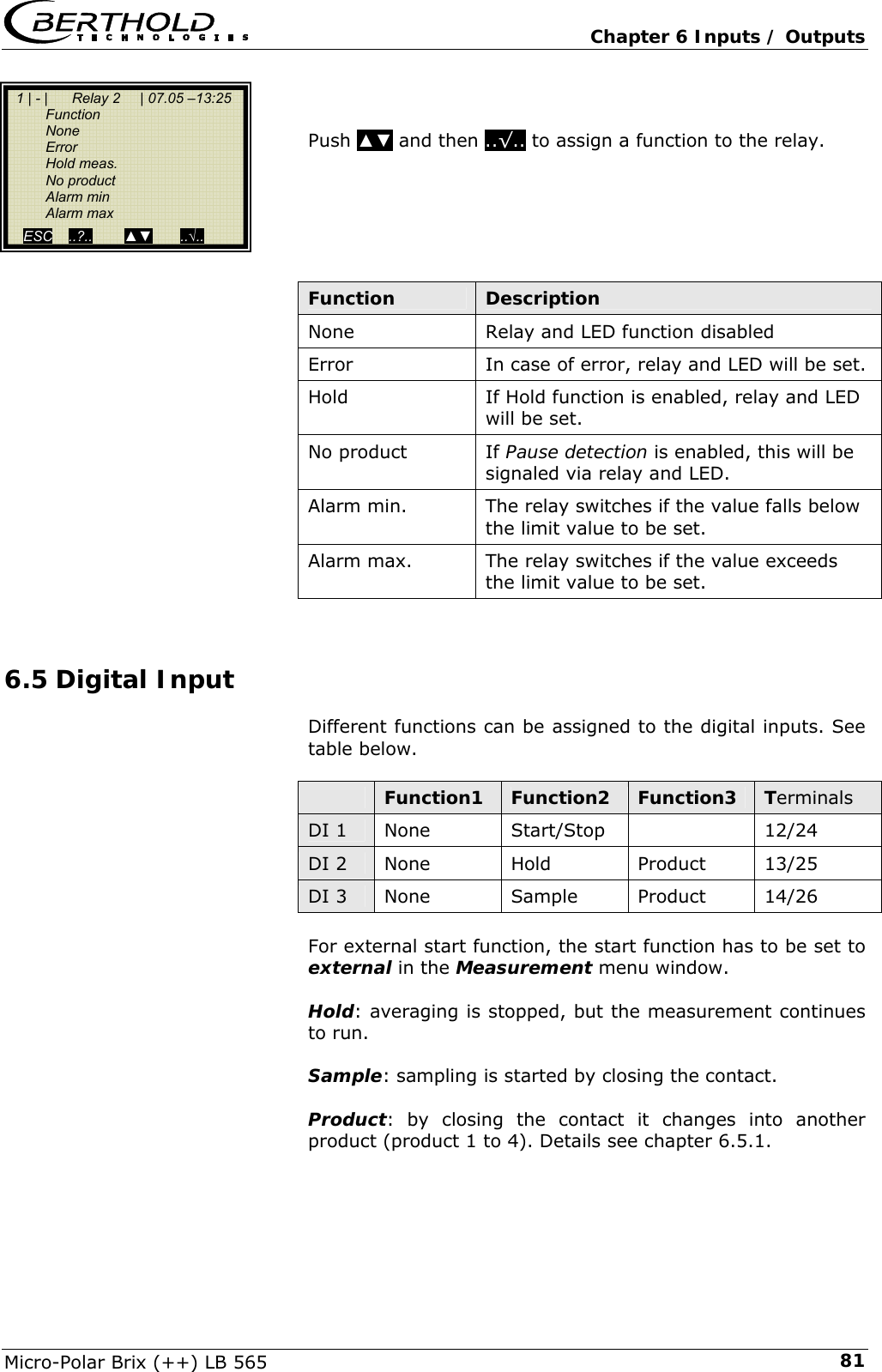
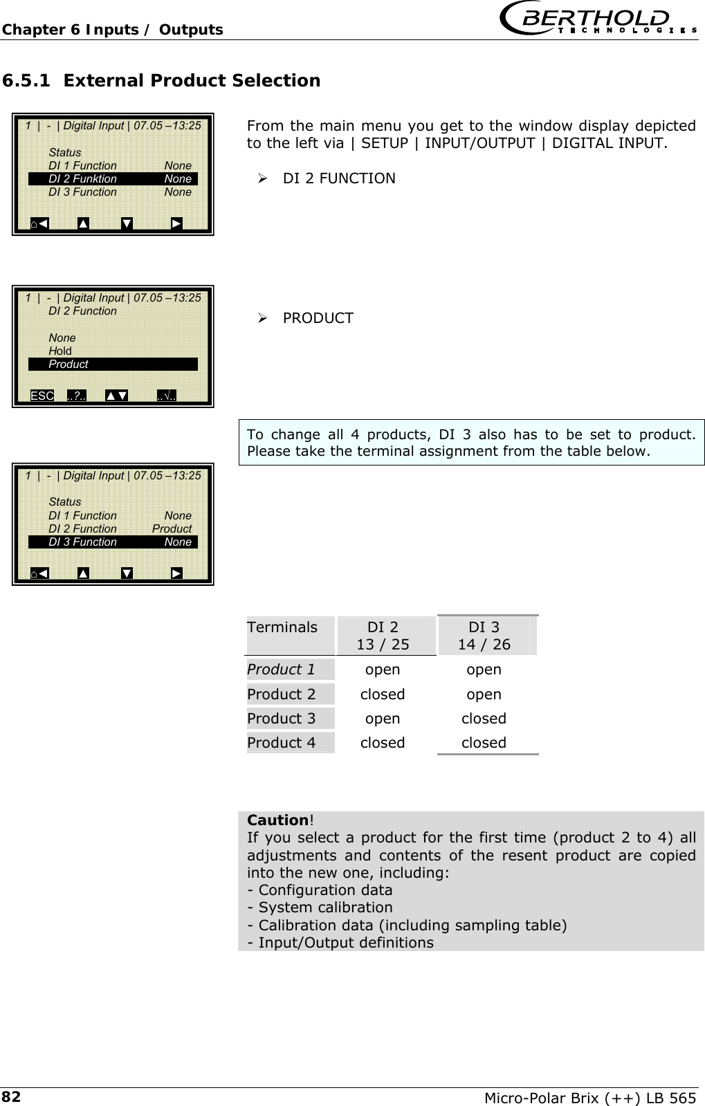
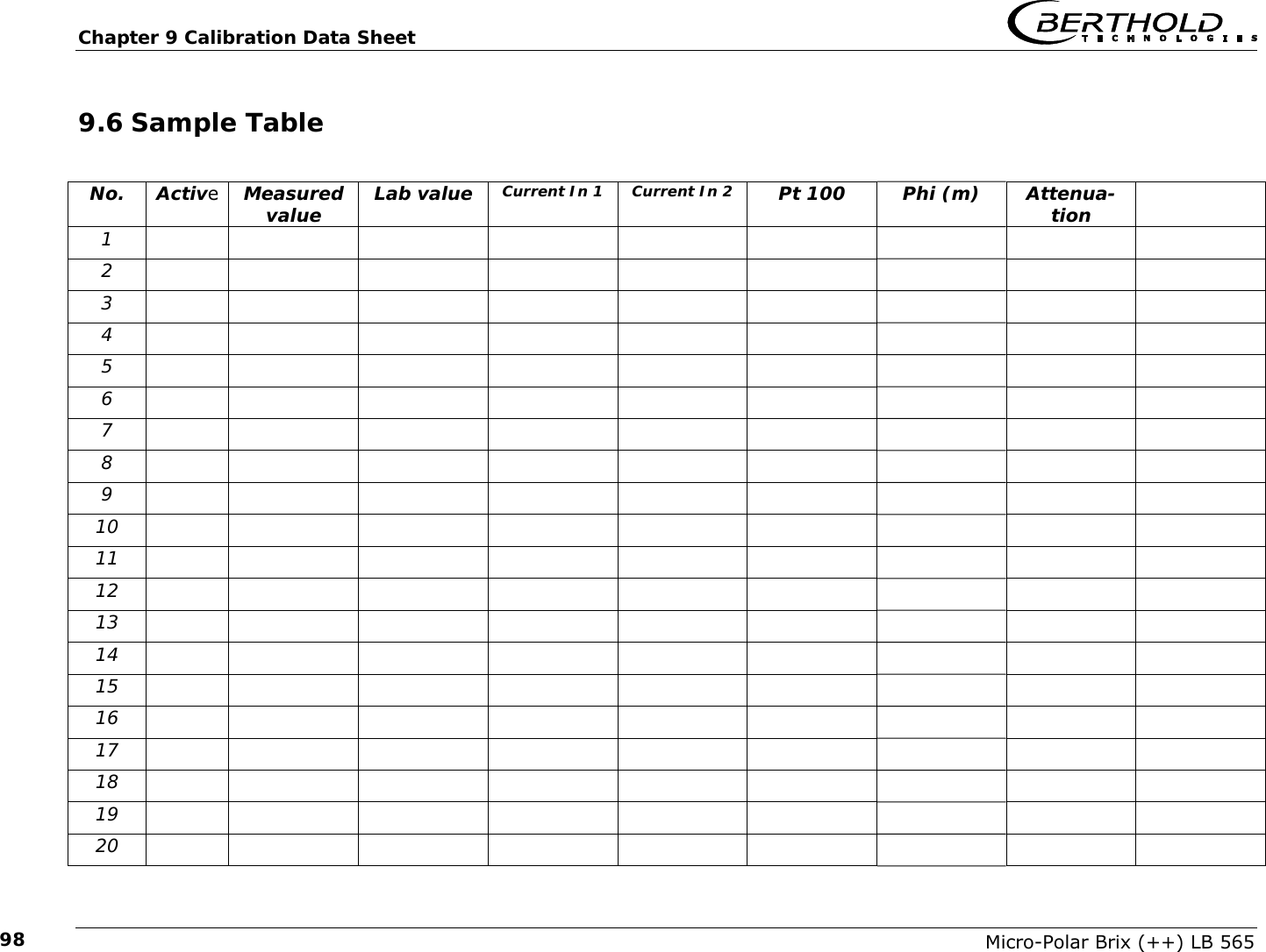
![Chapter 9 Calibration Data Sheet Micro-Polar Brix (++) LB 565 91Parameter Code-Nr. Information Calibration mode 0 1 Cal. order: Lineare regression Quadratic regression Calibration variable 0 1 2 Cal. base: Phase Attenuation Both (Phase and Attenuation) Compensation mode 0 1 Compensation mode: Additive Multiplicative Compensation fit 0 1 Compensation order: Lineare regression Quadratic regression Measure con-figuration 0 1 2 Process type: 1 Concentration 2 Concentrationen Split Concentration AO Assign Code 0 1 2 3 4 5 Assignment of current output: None Concentration Concentration 2 Current In 1 Current In 2 PT100 AO Alarm select code 0 1 2 3 Error current for current output: 22 mA 3.5 mA Hold Value Range selec-tion 0 1 Current output range: 0 … 20 mA 4 … 20 mA AI Range se-lection 0 1 Current input range: 0 … 20 mA 4 … 20 mA AI Enabled[2] State current in 2, enabled yes/No DO Function 0 1 2 3 4 5 Relay function: None Error Hold meas. No product Alarm min Alarm max DO Assign-ment 0 1 2 3 4 Relay: the min/max alarm is as-signed to …: Concentration Concentration 2 Current In 1 Current In 2 PT100](https://usermanual.wiki/Berthold-Technologies/FCC01X12/User-Guide-1100454-Page-183.png)
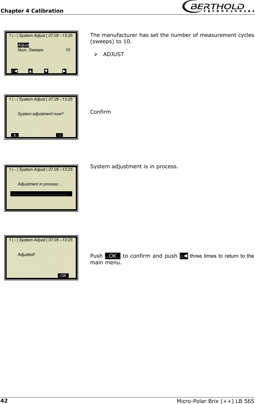
![Chapter 9 Calibration Data Sheet Micro-Polar Brix (++) LB 565 939.5.1 Examples of a start-up protocol Menu: Start of Setup: Examples of a start-up protocol Interpretation: ( * Only relevant for service) Product Entry Product1 Product2 Prod.3 Prod.4 Datalog Log type : 1 See code-list Log time : 2 See code-list Number of errors : 2 Number of entries into errorlog NTC temperature : 45.3 °C * max. NTC temperature : 46.7 °C * 9V power supply : 8.94 V * Info Tag : - Berthold LB number : LB 566 Unique device ID number : 2685 Serial number : 4.295E+09 Final assembly number : 000-000 Software version : 1.21 Software release date : 12.09.2007 Actual date : 17.03.2008 Record date Actual time : 00:24 Record time Measurement Measuring mode : 0 See code-list Start mode : 0 See code-list Filter damping value : 20 Number of average values Filter damping value[2] : 20 * Filter damping value[3] : 20 * Reset average : FALSE Plausibility Lower limit : 0 Min. Concentration Upper limit : 100 Max. Concentration Max. phase sigma : 100 Sigma max. Correlation Phi/Att : 6 Phi/Att ratio Auto-set mode : FALSE Auto set: ON/OFF Pause detection : FALSE Minimum attenuation : -15.0 dB Microwave Ref. cable length : 4.00 m Meas. cable length : 4.00 m Wave band selection : 1 * Start frequency : 2 * Internal Attenuation : 0 * Marker Marker name : Mark1 For Concentration Marker value : 50 For Concentration Marker name[2] : Mark2 For Concentration 2 Marker value[2] : 50 For Concentration 2 System adjust Nbr of sweeps for reference: 10](https://usermanual.wiki/Berthold-Technologies/FCC01X12/User-Guide-1100454-Page-185.png)
![Chapter 9 Calibration Data Sheet Micro-Polar Brix (++) LB 565 94 Compensation input : 0 See code-list Compensation reference : 0 Calibrate concentration Calibration mode : 0 See code-list Calibration variable : 0 See code-list Phase coefficients : -0.19 A1 Phase coefficients[2] : 0 A2 Attenuation coefficients : 0 B1 Attenuation coefficients[2] : 0 B2 Constant coefficient : 50 C Compensation mode : 0 See code-list Compensation fit : 0 See code-list Compensation reference : 0 Phase coeff. for comp. : 0 C_Ph1 Phase coeff. for comp.[2] : 0 C_Ph2 Attenuation coeff. for comp : 0 C_dB1 Attenuation coeff. for comp[2] 0 C_dB2 Adjust factor : 1 Adjust offset : 0 Compensation input : 0 See code-list Compensation reference : 0 Calibrate concentration 2 Calibration mode : 0 See code-list Calibration variable : 0 See code-list Phase coefficients : -0.19 A1 Phase coefficients[2] : 0 A2 Attenuation coefficients : 0 B1 Attenuation coefficients[2] : 0 B2 Constant coefficient : 50 C Compensation mode : 0 See code-list Compensation fit : 0 See code-list Compensation reference : 0 Phase coeff. for comp. : 0 C_Ph1 Phase coeff. for comp.[2] : 0 C_Ph2 Attenuation coeff. for comp : 0 C_dB1 Attenuation coeff. for comp[2] 0 C_dB2 Adjust factor : 1 Adjust offset : 0 Advanced Tara Phase (°/GHz) : 0.00 °/GHz Tara Attenuation (dB) : 0.00 dB Measure configuration : 0 Process type: see code-list Range split value : 75 Split value](https://usermanual.wiki/Berthold-Technologies/FCC01X12/User-Guide-1100454-Page-186.png)
![Chapter 9 Calibration Data Sheet Micro-Polar Brix (++) LB 565 95 AO Assign code : 1 Assignment: see code-list Current out 1 AO Upper range value : 100.00% Upper value AO Lower range value : 0.00% Lower value AO Current value : 4.00 mA Live current AO Alarm select code : 2 Error current: see code-list AO Error current value : 22.00 mA Error current value AO Assign code[2] : 0 Assignment: see code-list Current out 2 AO Upper range value[2] : 100 Upper value AO Lower range value[2] : 0 Lower value Range selection[2] : 1 Range AO Current value[2] : 4.00 mA Live current AO Alarm select code[2] : 2 Error current: see code-list AO Error current value[2] : 22.00 mA Error current value AI Enabled : FALSE Current in 1 AI Range selection : 1 Range: see code-list AI Upper range value : 100 Upper value AI Lower range value : 0 Lower value AI Current : 0.00 mA Live current AI Enabled[2] : FALSE Current in 2 AI Range selection[2] : 1 Range: see code-list AI Upper range value[2] : 100 Upper value AI Lower range value[2] : 0 Lower value AI Current[2] : 0.02 mA Live current AI Enabled[3] : TRUE PT100 input Pt100 value : 2.8 °C Live value Relay 1 DO Function : 1 Function: see code-list DO Assignment : 0 Assignment: see code-list DO Threshold : 0.00% * DO Hysteresis : 5.00% * Relay 2 DO Function[2] : 2 Function: see code-list DO Assignment[2] : 0 Assignment: see code-list DO Threshold[2] : 0.00% * DO Hysteresis[2] : 5.00% * DI Function selection : 0 Function digital input 1 DI Function selection[2] : 0 Function digital input 2 Digital input DI Function selection[3] : 0 Function digital input 3 Printout mode : 1 Access level : 2 Language : 1 End of Setup](https://usermanual.wiki/Berthold-Technologies/FCC01X12/User-Guide-1100454-Page-187.png)
![Chapter 9 Calibration Data Sheet Micro-Polar Brix (++) LB 565 96 Start of Reference Data System adjustment data: Product 1: Mean Atten.: 46.8509 dB Phase at fm: 42.6285 deg/GHz Phase offset: -825.586 deg Phase slope: 380.984 deg/GHz Phase sigma: 0.24575 Frequency[GHz] Phase[Deg] Atten.[dB] 2.42 96.41 46.2 2.43 100.71 46.8 * 2.44 103.08 47.13 2.45 108.12 46.84 2.46 111.75 47.28 Start of Sample Data: Sample Table Product 1: Sample Data for Concentration 1: Sample: Active: Kon.(%): Lab.(%): AIN1(°C): AIN2(°C): Temp.(°C): Phi.(°/GHz): Att.(dB): 1|16.03 - 20:53 TRUE 50.0193 0 0 0 2.83 -0.1 -0.16 2|17.03 - 00:22 TRUE 50.1061 0 0 0 2.71 -0.56 0.18 Correlation factor between lab and meas values: 1 End of Sample Data Do not use following data!](https://usermanual.wiki/Berthold-Technologies/FCC01X12/User-Guide-1100454-Page-188.png)