Beyerdynamic MIX10NG2 10 Channel Stereo Mixing System User Manual
Beyerdynamic 10 Channel Stereo Mixing System Users Manual
Users Manual

BEDIENUNGSANLEITUNG
OPERATING INSTRUCTIONS
MIX 10 NG2
10-Kanal-Stereo-Mischsystem
10-Channel-Stereo-Mixing-System
MIX10NG2_BA_DE_2008:MIX10NG_BA_DE 01.02.2008 10:29 Uhr Seite 1

MIX10NG2_BA_DE_2008:MIX10NG_BA_DE 01.02.2008 10:29 Uhr Seite 2

MIX 10 NG2 – Inhalt 3
deutsch
1. Ausführung. . . . . . . . . . . . . . . . . . . . . . . . . . . . . . . . . . . . . . . . . . . . . . . . . . . . . . . . . . . . . . . . . . . . . . . . . . . . . . 4
2. Wichtige Sicherheitshinweise . . . . . . . . . . . . . . . . . . . . . . . . . . . . . . . . . . . . . . . . . . . . . . . . . . . . . . . . . . . . . . . . 4
3. Bedien- und Kontrollelemente. . . . . . . . . . . . . . . . . . . . . . . . . . . . . . . . . . . . . . . . . . . . . . . . . . . . . . . . . . . . . . . . 6
4. Anschlüsse . . . . . . . . . . . . . . . . . . . . . . . . . . . . . . . . . . . . . . . . . . . . . . . . . . . . . . . . . . . . . . . . . . . . . . . . . . . . . . 7
4.1 Mikrofoneingänge. . . . . . . . . . . . . . . . . . . . . . . . . . . . . . . . . . . . . . . . . . . . . . . . . . . . . . . . . . . . . . . . . . . 7
4.1.1 Vorrangschaltung („Prior“) . . . . . . . . . . . . . . . . . . . . . . . . . . . . . . . . . . . . . . . . . . . . . . . . . . . . . . . . . . . . 7
4.2 Tonträgereingänge. . . . . . . . . . . . . . . . . . . . . . . . . . . . . . . . . . . . . . . . . . . . . . . . . . . . . . . . . . . . . . . . . . . 7
4.3 Mix-Eingang . . . . . . . . . . . . . . . . . . . . . . . . . . . . . . . . . . . . . . . . . . . . . . . . . . . . . . . . . . . . . . . . . . . . . . . 7
4.4 Record Out - Aufnahmeausgang . . . . . . . . . . . . . . . . . . . . . . . . . . . . . . . . . . . . . . . . . . . . . . . . . . . . . . . . 7
4.5 Master Output - Summenausgang. . . . . . . . . . . . . . . . . . . . . . . . . . . . . . . . . . . . . . . . . . . . . . . . . . . . . . . 7
4.6 Subgroup-Ausgang . . . . . . . . . . . . . . . . . . . . . . . . . . . . . . . . . . . . . . . . . . . . . . . . . . . . . . . . . . . . . . . . . . 7
4.7 Netzanschluss . . . . . . . . . . . . . . . . . . . . . . . . . . . . . . . . . . . . . . . . . . . . . . . . . . . . . . . . . . . . . . . . . . . . . . 8
5. Zuteilung der Eingangskanäle per Dip-Schalter . . . . . . . . . . . . . . . . . . . . . . . . . . . . . . . . . . . . . . . . . . . . . . . . . . . 8
6. Inbetriebnahme . . . . . . . . . . . . . . . . . . . . . . . . . . . . . . . . . . . . . . . . . . . . . . . . . . . . . . . . . . . . . . . . . . . . . . . . . . 8
7. Fernbedienung über RS 232 . . . . . . . . . . . . . . . . . . . . . . . . . . . . . . . . . . . . . . . . . . . . . . . . . . . . . . . . . . . . . . . . . 8
7.1 Software Installation . . . . . . . . . . . . . . . . . . . . . . . . . . . . . . . . . . . . . . . . . . . . . . . . . . . . . . . . . . . . . . . . . 8
7.2 Anschluss . . . . . . . . . . . . . . . . . . . . . . . . . . . . . . . . . . . . . . . . . . . . . . . . . . . . . . . . . . . . . . . . . . . . . . . . . 8
7.3 Bedienung. . . . . . . . . . . . . . . . . . . . . . . . . . . . . . . . . . . . . . . . . . . . . . . . . . . . . . . . . . . . . . . . . . . . . . . . . 9
7.3.1 Bedienfeld . . . . . . . . . . . . . . . . . . . . . . . . . . . . . . . . . . . . . . . . . . . . . . . . . . . . . . . . . . . . . . . . . . . . . . . . . 9
7.3.2 Einstellung. . . . . . . . . . . . . . . . . . . . . . . . . . . . . . . . . . . . . . . . . . . . . . . . . . . . . . . . . . . . . . . . . . . . . . . . 10
7.3.3 COM . . . . . . . . . . . . . . . . . . . . . . . . . . . . . . . . . . . . . . . . . . . . . . . . . . . . . . . . . . . . . . . . . . . . . . . . . . . . 10
7.4 Spezifikation der RS 232 Schnittstelle . . . . . . . . . . . . . . . . . . . . . . . . . . . . . . . . . . . . . . . . . . . . . . . . . . . 12
8. Technische Daten . . . . . . . . . . . . . . . . . . . . . . . . . . . . . . . . . . . . . . . . . . . . . . . . . . . . . . . . . . . . . . . . . . . . . . . . 16
9. Blockschaltbild . . . . . . . . . . . . . . . . . . . . . . . . . . . . . . . . . . . . . . . . . . . . . . . . . . . . . . . . . . . . . . . . . . . . . . . . . . 17
Konformitätserklärung . . . . . . . . . . . . . . . . . . . . . . . . . . . . . . . . . . . . . . . . . . . . . . . . . . . . . . . . . . . . . . . . . . . . . . . 34
MIX10NG2_BA_DE_2008:MIX10NG_BA_DE 01.02.2008 10:29 Uhr Seite 3
MIX 10 NG2 – Sicherheitsinformationen 4
Sie haben sich für das 10-Kanal-Stereo-Mischsystem MIX 10 NG2 von beyerdynamic entschieden. Vielen Dank für Ihr Vertrauen. Nehmen Sie
sich bitte einige Minuten Zeit und lesen Sie diese Bedienungsanleitung vor Inbetriebnahme aufmerksam durch.
1. Ausführung
MIX 10 NG2 10-Kanal-Stereo-Mischsystem für 230 V. . . . . . . . . . . . . . . . . . . . . . . . . . . . . . Best.-Nr. 486.655
MIX 10 NG2 dito, jedoch für 117 V . . . . . . . . . . . . . . . . . . . . . . . . . . . . . . . . . . . . . . . . . . . Best.-Nr. 486.663
Das 10-Kanal-Stereo-Mischsystem MIX 10 NG2 hat 6 mischbare Mikrofoneingänge und 4 umschaltbare, der Mikrofonsumme beigemischte
Tonträgereingänge mit einem gemeinsamen Summenpegelsteller (Master) und zusätzlichem Zonenausgang (Subgroup). Die Mikrofonein-
gänge können wahlweise als sprachgesteuerter Vorrangeingang (Prior) angewählt werden. Alle nicht als „Prior“ angewählten Quellen
werden dann weich ausgeblendet.
Der MIX 10 NG2 kann über die standardisierte, serielle Schnittstelle RS 232 und die mitgelieferte Software bedient werden. Der MIX 10 NG2
verfügt über eine separate 2-Band-Klangregelung und Mute-Schalter pro Mikrofoneingang. Alle Signale können über rückseitige Dip-Schalter
entweder auf den Masterausgang oder den Sub-Ausgang geroutet werden. Auch der Sub-Ausgang ist über die Software regelbar.
Jeder Line-Eingang verfügt über einen separaten Pegelsteller auf der Rückseite.
2. Wichtige Sicherheitshinweise
ON: Einschalten
OFF: Ausschalten
ACHTUNG
Wichtige Sicherheitsmaßnahmen, die bei Nichtbeachtung zu einer Verletzung oder zum Tod des Anwenders führen können.
VORSICHT
Wichtige Sicherheitsmaßnahmen, die bei Nichtbeachtung zur Beschädigung des Produkte führen können.
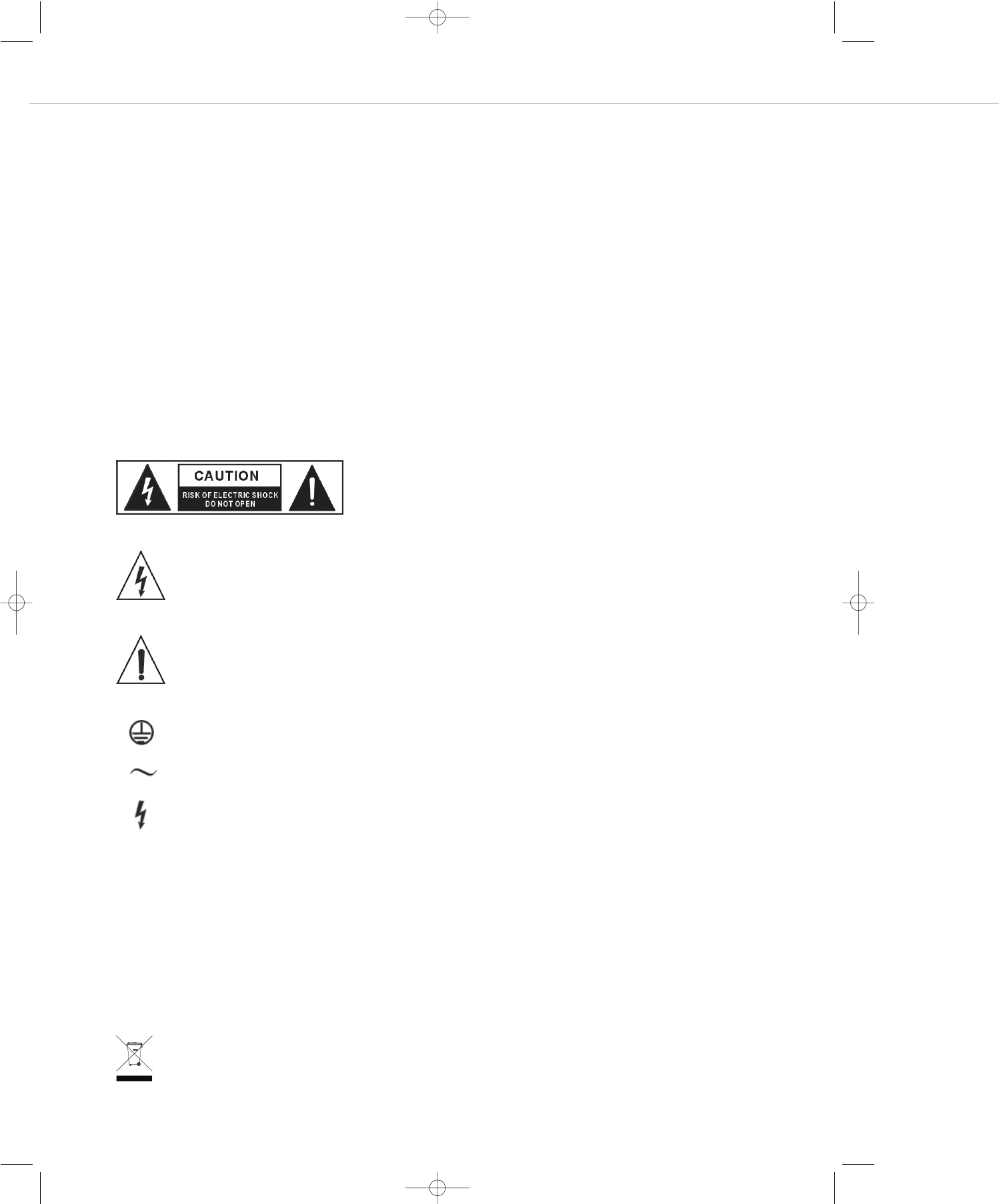
Dieses Symbol zeigt an, dass gefährliche Spannungswerte, die ein Stromschlagrisiko
darstellen, innerhalb dieses Gerätes auftreten können.
Dieses Symbol zeigt an, dass die diesem Gerät beiliegende Bedienungsanleitung
wichtige Betriebs- und Wartungsanweisungen enthält.
Schutzleiterzentralanschluss
Wechselstrom
Gefahr durch einen elektrischen Schlag bei Berührung! Lebensgefahr!
Dieses Produkt darf am Ende seiner Lebensdauer nicht über den normalen Haushaltsabfall entsorgt werden, sondern muss an
einem Sammelpunkt für das Recycling von elektrischen und elektronischen Geräten abgegeben werden. Das Symbol auf dem
Produkt, der Gebrauchsanweisung oder der Verpackung weist darauf hin.
MIX10NG2_BA_DE_2008:MIX10NG_BA_DE 01.02.2008 10:29 Uhr Seite 4

MIX 10 NG2 – Sicherheitsinformationen 5
deutsch
Allgemein
• LESEN Sie die Bedienungsanleitung.
• BEWAHREN Sie diese Bedienungsanleitung auf.
• BEFOLGEN Sie die aufgeführten Bedienungs- und Sicherheitshinweise.
• Befolgen Sie bei der Installation alle Herstelleranweisungen.
• Verwenden Sie nur vom Hersteller empfohlenes Zubehör.
Haftungsausschluss
• Die Firma beyerdynamic GmbH & Co. KG übernimmt keine Haftung für Schäden am Produkt oder Verletzungen von Personen aufgrund
unachtsamer, unsachgemäßer, falscher oder nicht dem vom Hersteller angegebenen Zweck entsprechender Verwendung des Produkts.
Standort
• Das Gerät muss so aufgestellt werden, dass die Steckverbindungen leicht zugänglich sind.
• Wenn Sie das Gerät an einen anderen Ort transportieren, achten Sie darauf, dass es ausreichend gesichert ist und niemand durch ein
eventuelles Herunterfallen oder Stoßen am Gerät verletzt werden kann.
Brandschutz
• Stellen Sie keine schweren Gegenstände auf das Netzkabel. Dieses könnte beschädigt werden und einen elektrischen Schlag oder einen
Brand verursachen.
• Stellen Sie niemals offene Brandquellen (z.B. Kerzen) auf das Gerät.
Feuchtigkeit / Wärmequellen
• Setzen Sie das Gerät niemals Regen oder hoher Feuchtigkeit aus. Installieren Sie es daher nicht in unmittelbarer Nähe von Swimming Pools,
Duschanlagen, feuchten Kellerräumen oder sonstigen Bereichen mit außergewöhnlich hoher Luftfeuchtigkeit.
• Stellen Sie niemals mit Flüssigkeiten gefüllte Gegenstände (z.B. Vasen oder Trinkgläser) auf das Gerät. Denn Flüssigkeiten in den Geräten
können einen Kurzschluss verursachen.
• Installieren und betreiben Sie das Gerät auch niemals in unmittelbarer Nähe von Heizkörpern, Beleuchtungsanlagen oder anderen
wärmeerzeugenden Geräten.
Ventilation
• Dieses Gerät benötigt eine ausreichende Ventilation. Decken Sie die Lüftungsöffnungen nicht ab. Wenn die Eigenwärme nicht abgeführt
wird, kann das Gerät beschädigt oder brennbare Materialien in unmittelbarer Nähe können entzündet werden. Achten Sie daher darauf,
dass die Luft durch die Lüftungsöffnungen frei zirkulieren kann und halten Sie brennbare Materialien fern.
• Stecken Sie keine Gegenstände in die Lüftungs- und andere Öffnungen. Sie könnten das Gerät beschädigen und/oder sich verletzen.
Anschluss
• Das Gerät muss an eine Netzsteckdose mit Schutzkontakt angeschlossen werden.
• Verlegen Sie alle Kabel stets so, dass sie nicht durch scharfe Gegenstände geknickt oder gar durchgetrennt werden können.
• Verlegen Sie alle Anschlusskabel so, dass niemand darüber stolpern und sich verletzen kann.
• Schalten Sie bei allen Arbeiten an den Ein- und Ausgängen die Stromzufuhr aus.
• Überprüfen Sie, ob die Anschlusswerte mit der vorhandenen Netzstromversorgung übereinstimmen. Bei Anschluss des Systems an die
falsche Stromversorgung können ernsthafte Schäden entstehen. Eine falsche Netzspannung kann das Gerät beschädigen oder einen
elektrischen Schlag verursachen.
• Nehmen Sie das Gerät bei einem Gewitter oder wenn Sie es längere Zeit nicht benutzen vom Netz.
• Wenn Sie defektes oder ungeeignetes Zubehör anschließen, kann das Gerät beschädigt werden.
• Wenn durch das Gerät eine Sicherung defekt oder ein Kurzschluss verursacht wurde, nehmen Sie es vom Netz und lassen Sie es überprüfen
und reparieren.
• Fassen Sie das Netzkabel nicht mit nassen Händen an und an den Kontaktstiften sollte sich kein Wasser oder Staub befinden.
In beiden Fällen könnten Sie einen elektrischen Schlag erleiden.
• Das Netzkabel muss fest angeschlossen sein. Ist es lose, besteht Brandgefahr.
• Ziehen Sie das Netzkabel immer am Stecker vom Netz und/oder vom Gerät - niemals am Kabel. Das Kabel könnte beschädigt werden und
einen elektrischen Schlag oder Brand verursachen.
• Setzen Sie das Gerät nicht ein, wenn der Netzstecker beschädigt ist.
• Durchtrennen Sie niemals interne oder externe Schutzleiterverbindungen.
• Nehmen Sie am Netzkabel und Netzstecker keine unerlaubten Änderungen vor.
Reinigung
• Halten Sie das Produkt staubfrei zu Ihrer eigenen Sicherheit.
• Reinigen Sie das Gerät nur mit einem leicht feuchtem oder trockenem Tuch. Verwenden Sie niemals Lösungsmittel, da diese die Oberfläche
beschädigen.
Fehlerbeseitigung / Reparatur
• Öffnen Sie nicht eigenmächtig das Gerät. Sie könnten einen elektrischen Schlag erleiden.
• Im Innern des Gerätes befinden sich keine Komponenten, die vom Anwender gewartet werden können.
• Überlassen Sie alle Servicearbeiten nur autorisiertem Fachpersonal.
Elektromagnetische Kompatibilität
Zur Gewährleistung der elektromagnetischen Kompatibilität dürfen nachfolgend aufgeführte Kabellängen nicht überschritten werden:
1) Audio in 3 m
2) Audio output 10 m
3) RS 232 3 m
4) REC out 1 m
5) REC in 1 m
MIX10NG2_BA_DE_2008:MIX10NG_BA_DE 01.02.2008 10:29 Uhr Seite 5
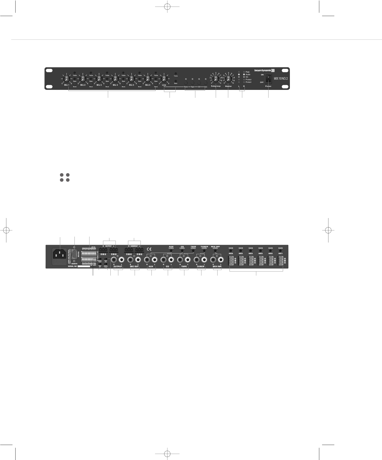
(1) Pegelsteller Mikrofoneingänge (Mic 1 bis Mic 6) mit jeweiliger Klangregelung Höhen (Treble), Tiefen (Bass)
und Stummschaltung (Mute)
(2) Pegelsteller Line zum Einstellen des Pegels von CD, Tape, Tuner oder Aux mit Klangregelung Höhen (Treble) und Tiefen (Bass)
(3) Quellenwahlschalter für aktiven Line-Eingang (CD, Tape, Tuner, Aux) mit LED-Statusanzeige
(4) Subgroup - Lautstärkeregelung
(5) Master - Lautstärkeregelung
(6) LED-Anzeigen für linken (L) und rechten (R) Kanal
Peak - Rote LED leuchtet, wenn das Signal übersteuert ist.
Audio - Gelbe LED leuchtet, wenn das Ausgangssignal mit einem Pegel von 0 dB vorhanden ist.
On - Grüne LED leuchtet, wenn das Gerät eingeschaltet ist.
Protect - Rote LEDs dienen der Überwachung der symmetrischen Master-Ausgänge (8).
Die oberen LEDs stehen für die Überwachung des positiven Ausgangssignals.
Die unteren LEDs stehen für die Überwachung des negativen Ausgangssignals.
2 bzw. 3 leuchtet jeweils bei Kurzschluss gegen Masse (Pin 1).
2 und 3 leuchten gleichzeitig bei Kurzschluss zwischen Pin 2 und 3.
(7) Netzschalter
Rückseite
MIX 10 NG2 – Bedien- und Kontrollelemente 6
3. Bedien- und Kontrollelemente
Vorderseite
(1) (3) (6)(4) (5) (7)(2)
(8) Master-Output R + L, Klemmanschluss, 3-pol., symmetrisch
(9) Subgroup R + L, Klemmanschluss, 3-pol., symmetrisch
(10) Netzanschluss (230 V/115 V) mit Sicherung (315 mA/T / 500 mA/T)
(11) RS 232 Schnittstelle, Sub-D 9-pol., male
(12) Ground Lift, trennt Betriebsmasse von Netzerde zur Kompensation von Brummeinstreuungen. Ground Lift ist aktiv, wenn
der Schalter rechts steht.
(13) Phantom Power – Off/On, schaltet 27 V Phantomspeisung für die Verwendung von Kondensatormikrofonen zu ober ab
(14) Master Mono, brückt die Master-Ausgänge in einen Mono-Betrieb, Stereo-Line-Quellen werden auf den Master L/R Ausgängen
jeweils Mono ausgegeben
(15) Sub Mono, brückt die Sub-Ausgänge in einen Mono-Betrieb, Stereo-Line-Quellen werden auf den Subgroup L/R Ausgängen
jeweils Mono ausgegeben
(16) Dip-Schalter zur Zuordung der Eingangskanäle auf den Masterausgang (M) oder Subgroup-Ausgang (S).
Befindet sich der Dip-Schalter in der oberen Position, ist der Eingangskanal auf den jeweiligen Ausgang geroutet.
(17) Master Output, +6 dB, Summenausgang R/L unsymmetrisch, Cinch
(18) REC - Aufnahmeausgang L/R für Mikrofonsumme
(19) Aux-Eingang mit separatem Pegelsteller
(20) CD-Eingang mit separatem Pegelsteller
(21) Tape-Eingang mit separatem Pegelsteller
(22) Tuner-Eingang mit separatem Pegelsteller
(23) MIX INP - Stereo-Erweiterungseingang mit separatem Pegelsteller für Toneinspielungen von z.B. Mischpult oder weiteren MIX 10 NG2
(24) MIC 1 - MIC 6 - Elektronisch symmetrierte Mikrofoneingänge mit Gaineinstellung (Eingangsempfindlichkeit),
Klemmanschluss, 3-pol.
22
33
LR
(8) (9)(10) (11)
(12) (13)
(17)(15)(14) (18) (19) (20) (21) (22) (23) (24)
(16)
MIX10NG2_BA_DE_2008:MIX10NG_BA_DE 01.02.2008 10:29 Uhr Seite 6

MIX 10 NG2 – Anschlüsse 7
deutsch
4. Anschlüsse
4.1 Mikrofoneingänge
Auf der Geräterückseite befinden sich sechs Mikrofonanschlüsse (24) mit abnehmbarem Klemmanschluss. Die Mikrofone werden symmetrisch
angeschlossen. Bei jedem Eingang kann die Eingangsempfindlichkeit (Gain) auf der Geräterückseite eingestellt werden (0- +55dB). Die Ein-
gangslautstärke wird auf der Vorderseite mit den Lautstärkereglern (1) oder über die mitgelieferte Software eingestellt. Die Mikrofoneingänge
können über die Software mit der „Prior“-Funktion auf Vorrang geschaltet werden (siehe Kapitel 4.1.1 „Vorrang schal tung“).
Achtung:
Für alle Mikrofoneingänge kann eine Phantomspeisung von +27 V zugeschaltet werden (13). Wenn Sie Geräte mit unsymmetrischen
Ausgängen anschließen, muss ein Koppelkondensator eingefügt werden bzw. die Phantom speisung abgeschaltet werden.
4.1.1 Vorrangschaltung („Prior“)
Die Priorität der bevorrechtigten Mikrofoneingänge ist sprachgesteuert (Prior-Funktion). Die Vorrangschaltung ist für alle Mikrofoneingänge
möglich und wird über die mitgelieferte Software angewählt. Alle nicht als „Prior“ angewählten Quellen werden dann weich ausgeblendet.
Die ausgeblendeten Signale werden um einen frei definierbaren Wert abgesenkt. Die Ausblendtiefe, Ausblend- und Einblendgeschwindigkeit
werden per Software eingestellt bzw. geändert.
Eine Ausblendung erfolgt durch das Besprechen des an einem der bevorrechtigten Mikrofoneingänge angeschlossenen Mikrofons.
Im Auslieferungszustand ist die Prior-Funktion nicht aktiv. Falls diese gewünscht ist, muss sie über die Software aktiviert werden (siehe Kapitel
7.3.1 „Bedienfeld“).
4.2 Tonträgereingänge
Auf der Geräterückseite des MIX 10 NG2 befinden sich vier getrennte Tonträgeranschlüsse (Cinch). Einer dieser vier Tonträgereingänge kann
mit dem entsprechenden Quellenwahlschalter (3) ausgewählt werden. Die Anschlüsse sind unsymmetrisch ausgeführt und eignen sich für
Stereo-Quellen. Bei jedem Eingang kann die Eingangsempfindlichkeit (Level) auf der Geräterückseite eingestellt werden, um Lautstärkeunter-
schiede verschiedener Zuspieler ausgleichen zu können. Die Line-Summenlautstärke wird auf der Vorderseite mit dem Lautstärkeregler (2)
oder über die Software eingestellt.
Die Quellenanwahl kann sowohl über die frontseitigen Taster, als auch über die mitgelieferte Software erfolgen.
4.3 Mix-Eingang
Der Mix-Eingang (Cinch) (23) befindet sich auf der Geräterückseite. Der Anschluss ist unsymmetrisch ausgeführt und eignet sich für Stereo-
Toneinspielungen. Dieser Eingang dient zum Anschluss von z.B. weiteren Mischsystemen wie Mischpulte oder MIX 10 NG2.
Beim Mix-Eingang kann die Eingangsempfindlichkeit (Level) auf der Geräterückseite eingestellt werden. Dieser Eingang wird nicht von der
Line-Lautstärkeregelung beeinflusst.
4.4 Record Out - Aufnahmeausgang
Die Aufnahmebuchse (18) ist unsymmetrisch beschaltet (0 dB). Sie dient zum Anschluss von Tonaufzeichnungsgeräten. Das Signal, das zur
Aufnahme zur Verfügung steht, ist die Summe der Mikrofon- und Lineeingänge (Master Output) vor Summenlautstärkeregelung.
4.5 Master Output - Summenausgang
Der Master Output (8), +6 dBu ist ein symmetrischer Ausgang mit 3-pol. Schraubklemmanschluss, der zum Anschluss des MIX 10 NG2 an
eine externe Endstufe/Endverstärker dient. Hier liegen alle Mikrofon- und Tonträgersignale, die per Dip-Schalter auf den Masterausgang
geroutet wurden, als Summe an. Der Master Output (8) ist für lange Kabelwege geeignet. Der Master-Ausgang (L/R) wird auf der Vorderseite
mit dem Lautstärkeregler (5) oder über die Software eingestellt.
Der Master Output (17), 0 dBu ist ein unsymmetrischer Ausgang an Stereo-Chinch-Buchsen, der als zusätzlicher Hilfsausgang dient. Er liegt
parallel zum Master Output (8). Der Master Output (17) eignet sich für kurze Kabelwege und kann z.B. direkt an den Eingang eines Hi-Fi
Verstärkers angeschlossen werden.
MIX10NG2_BA_DE_2008:MIX10NG_BA_DE 01.02.2008 10:29 Uhr Seite 7

MIX 10 NG2 – Inbetriebnahme 8
4.6 Subgroup-Ausgang
Der Subgroup-Ausgang (9), +6 dBu ist ein zusätzlicher symmetrischer Ausgang mit 3-pol. Schraubklemmanschluss, der zum Anschluss des
MIX 10 NG2 an eine externe Endstufe/Endverstärker dient. Hier liegen alle Mikrofon- und Tonträgersignale, die per Dip-Schalter auf den
Subgroup-Ausgang geroutet wurden, als Summe an. Der Subgroup-Ausgang (L/R) wird auf der Vorderseite mit dem Lautstärkeregler (4) oder
über die Software eingestellt. Der Subgroup-Ausgang (9) ist für lange Kabelwege geeignet.
4.7 Netzanschluss
Das Netzkabel wird an den Netzanschluss (10) angeschlossen. Beim Anschluss an das Netz, beachten Sie bitte, dass die Netzspannung des
Gerätes mit der ortsüblichen übereinstimmt.
5. Zuteilung der Eingangskanäle per Dip-Schalter
Die Dip-Schalter dienen der Zuordung der Eingangskanäle auf den Masterausgang (M) oder Subgroup-Ausgang (S). Befindet sich der
Dip-Schalter in der oberen Position, ist der Eingangskanal auf den jeweiligen Ausgang geroutet. Dies ermöglicht, den unterschiedlichen
Ausgangszonen (Subgroup (S) / Master (M)) getrennte Signale zuzuweisen.
6. Inbetriebnahme
Nachdem alle Anschlüsse (Netz, Mikrofon etc.) hergestellt worden sind, gehen Sie wie folgt vor, um das System in Betrieb zu nehmen:
1. Drehen Sie die Empfindlichkeit der an den MIX10 NG2 angeschlossenen Verstärker/Endstufen zurück (min.) und schalten Sie diese ab.
2. Stellen Sie alle frontseitigen Lautstärkeregler auf Maximum (Rechtsanschlag).
3. Schalten Sie das Mischsystem MIX 10 NG2 mit dem Ein- und Ausschalter (7) ein
4. Besprechen Sie das erste angeschlossene Mikrofon in einem typischen Besprechungsabstand und öffnen Sie den rückseitigen Gain-
Regler, bis die Audio-LED (6) bei lauter Besprechung klar leuchtet.
5. Wiederholen Sie den Vorgang für alle angeschlossenen Mikrofone.
6. Bringen Sie alle frontseitigen Lautstärkeregler in eine zu ¾ geöffnete Position.
7. Schalten Sie die angeschlossene Endstufe ein und erhöhen Sie deren Eingangsempfindlichkeit bis die gewünschte Beschallungslautstärke
erreicht ist.
8. Fixieren Sie diese Einstellung der Endstufe. Die Feinregelung kann nun über die frontseitigen Regler des Mix10 NG2 erfolgen.
7. Fernbedienung über RS 232
Für eine Bedienung und Konfiguration des MIX 10 NG2 über einen PC oder Mediensteuersystem ist der MIX 10 NG2 mit einem
RS 232 Anschluss (9-pol. Sub-D, male) ausgestattet.
7.1 Software Installation
• Die mitgelieferte Software dient der Konfiguration und Fernsteuerung des MIX 10 NG2.
• Die Software ist zur Verwendung mit dem Betriebssystem Windows®XP / Vista ausgelegt. Legen Sie die CD in das Laufwerk und starten
Sie die Installation. Folgen Sie dabei den Anweisungen auf dem Bildschirm.
7.2 Anschluss
• Verbinden Sie den Remote-Anschluss (11) über ein Standard RS 232-Anschlusskabel mit der seriellen Schnittstelle RS 232 an Ihrem PC.
• Vorsicht bei der Leitungslänge der RS232 Verbindung. Leistungsschwache PC-Schnittstellen und minderwertige Verbindungsleitungen
können die Kommunikation / Leistungslänge stark beeinträchtigen.
MIX10NG2_BA_DE_2008:MIX10NG_BA_DE 01.02.2008 10:29 Uhr Seite 8
MIX 10 NG2 – Bedienung 9
deutsch
7.3 Bedienung
7.3.1 Bedienfeld
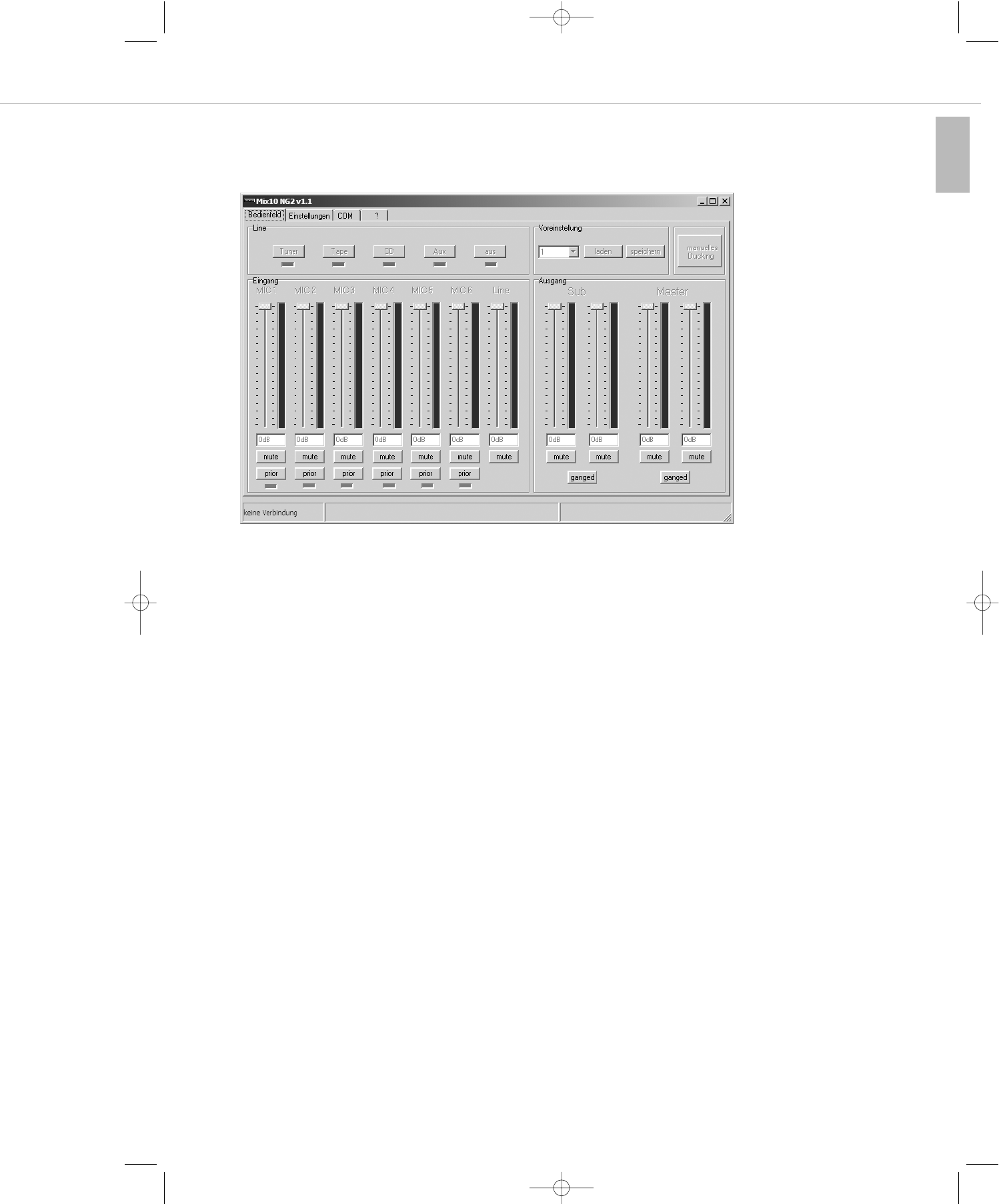
Wenn Sie das Programm „MIX 10 NG2“ starten, erscheint die Bedienober fläche Bedienfeld“.
Hier können die wichtigsten Lautstärkeregelungen und Umschaltfunktionen bedient werden:
Bedienfeld LINE
Im Bedienfeld „Line“ können Sie die an den MIX 10 NG2 angeschlossene/n Line-Quelle/n auswählen, indem Sie die entsprechende Schalt-
fläche anwählen: „Tuner“, „Tape“, „CD“, „Aux“. Mit „aus“ schalten Sie alle Line-Quellen ab.
Die LEDs unterhalb der Schaltflächen zeigen die aktuell eingestellte Line-Quelle des MIX 10 NG2 an. Auch Veränderungen durch eine front-
seitige Bedienung am MIX 10 NG2 selbst werden angezeigt.
Eingang
Pro Eingangskanal steht ein Fader sowie eine „Mute“-Taste zur Verfügung. Die Mikrofoneingangskanäle verfügen zudem über eine „Prior“-
Taste sowie eine LED-Anzeige.
Über die Fader kann die Eingangslautstärke der einzelnen Mikrofoneingangskanäle sowie die Lautstärke des angewählten Line-Signals in dB
geregelt werden. Die zugehörige „Mute“-Taste schaltet den jeweiligen Kanal stumm. Im Direkteingabefenster ist eine direkte Eingabe von
Dämpfungswerten in dB möglich.
Wird die „Prior“-Taste für einen oder mehrere der Mikrofonkanäle aktiviert, so befinden sich diese in einer Vorrangschaltung. Nach
Einstellung weiterer Parameter (Kapitel 7.3.2) lösen die angewählten Kanäle bei Besprechung eine Absenkung der übrigen Eingangskanäle
aus. Dies kann z.B. zur Absenkung der Hintergrundmusik bei Sprachdurchsagen in Kaufhäusern genutzt werden.
Ausgang
Für die Stereosummenausgänge „Master“ und „Subgroup“ stehen jeweils getrennte Regler für den linken und rechten Kanal mit zugehörigen
„Mute“-Tasten zur Verfügung. Diese ermöglichen eine Regelung der Summensignale, die über die Dip-Schalter auf den jeweiligen Kanal
geroutet wurden. Wird keine unterschiedliche Lautstärkeregelung für den linken und rechten Kanal gewünscht, so lassen sich die Kanäle
über die „Ganged“-Taste zu einer Summenregelung zusammenfassen. Ein Regler bedient dann die gesamte Master bzw. Subgroup-Lautstärke.
Manuelles Ducking
Hier kann die Absenkung der nicht bevorrechtigten Kanäle (Prior) von Hand ausgelöst werden. Dies dient in der Regel Testzwecken.
Voreinstellung
Der Mix 10 NG2 bietet die Möglichkeit im internen Speicher bis zu 3 Presets abzuspeichern. Ein Preset speichert alle Einstellungen, die in der
Software getätigt werden können wie z.B: Lautstärkeeinstellungen, Vorrangschaltung „prior“ usw.
Vorgehensweise zum Speichern von Presets:
1. Alle Softwareeinstellungen wie gewünscht vornehmen.
2. Im Drop-Down Menü „Voreinstellungen“ das gewünschte Preset (1,2 oder 3) anwählen.
3. Speichern klicken.
MIX10NG2_BA_DE_2008:MIX10NG_BA_DE 01.02.2008 10:29 Uhr Seite 9
MIX 10 NG2 – Bedienung 10
Vorgehensweise zum Laden von Presets:
1. Im Drop-Down Menü „Voreinstellungen“ das gewünschte Preset (1,2 oder 3) anwählen.
2. Laden klicken.
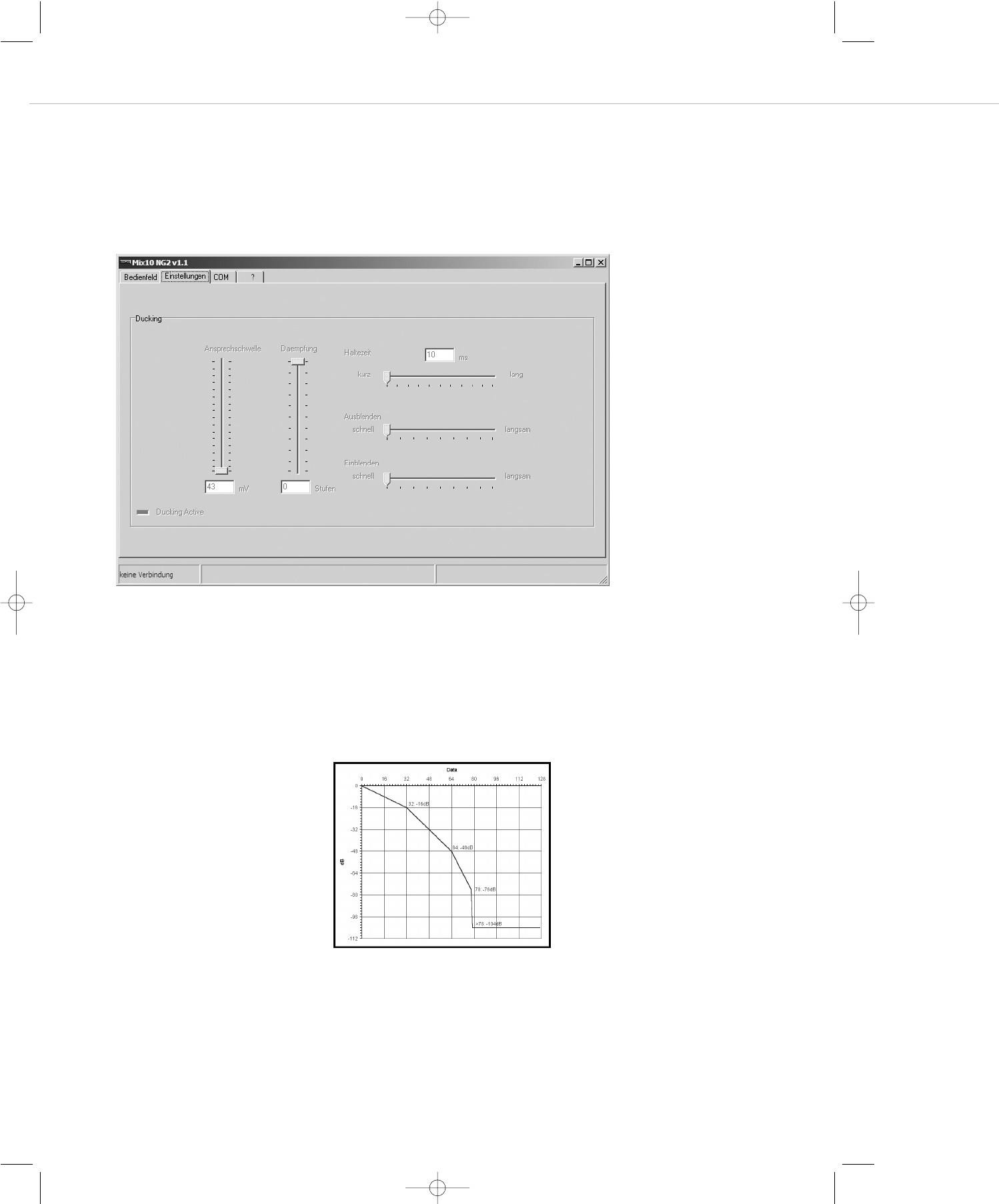
7.3.2 Einstellung
In diesem Bedienfeld werden alle Einstellungen, die für das Ducking im „Prior“ Modus benötigt werden, eingestellt.
Ansprechschwelle
Hier wird die Empfindlichkeit der Sprachaktivierung im Prior Modus eingestellt. Je weiter sich der Regler im unteren Bereich befindet, desto
weniger Eingangspegel des Prior-Mikrofons ist notwendig, um die Absenkung zu aktivieren. Das bedeutet, Sie stellen ein, mit welcher
Lautstärke in das Mikrofon gesprochen werden muss, damit das Ducking (Pegelabsenkung) aktiviert wird.
Spricht das Ducking auch bei geringster Einstellung der Ansprechschwelle nicht oder nur schlecht an, so muss die Mikrofoneingangsempfind-
lichkeit (Gain) an der Geräterückseite erhöht werden.
Daempfung
Hier wird eingestellt, um wie viele Stufen das nicht bevorrechtigte Signal gegenüber dem vollen Lautstärkepegel abgesenkt wird.
Haltezeit
Unter „Haltezeit“ können Sie die Wartezeit bis zum Beginn des Einblendens des zuvor abgeschwächten Signals einstellen. Diese Wartezeit
sollte nicht zu kurz gewählt werden.
Ausblenden / Einblenden
Hier wird eingestellt, wie schnell das Audiosignal nach Überschreiten des Schwellpegels ein- bzw. ausgeblendet wird. Typischerweise wählt
man kurze Ausblendzeiten, um bei Sprachdurchsagen nicht die erste Silbe der Durchsage zu verlieren. Die Einblendzeit wählt man dagegen
höher, um ein sanftes Wiedereinblenden z.B. der Hintergrundmusik zu erreichen.
Die ein- und darstellbaren Werte sind
folgendermassen abgestuft:
0 bis -16 dB in 0,5 dB-Schritten
-16 bis -48 dB in 1,0 dB-Schritten
-48 bis -76 dB in 2,0 dB-Schritten
-104 dB mute
MIX10NG2_BA_DE_2008:MIX10NG_BA_DE 01.02.2008 10:29 Uhr Seite 10

MIX 10 NG2 – Bedienung 11
deutsch
7.3.3 COM
Über das Bedienfeld „Port“ wird der gewünschte COM-Port aktiviert, über den der PC mit dem Mix10 NG2 verbunden werden soll.
Die Verbindungsgeschwindigkeit, Format- und Protokollangaben dienen rein informellen Zwecken und können nicht beeinflusst werden.
Die Taste „verbinden“ stellt eine COM-Verbindung zwischen Mix10 NG2 und PC her.
Einschaltzustand
Hier wird angegeben, in welchem Ausgangszustand sich der Mix10 NG2 nach dem Einschalten befindet. Es kann hierbei eines der zuvor ge-
speicherten Presets angewählt werden. Der Mix10 NG2 lädt dann nach dem Einschalten immer die Einstellungen des gewählten Startpresets
1,2 oder 3. Alternativ kann auch der Zustand gespeichert werden, bei dem das Gerät zuletzt abgeschaltet wurde. Dies geschieht durch
Anwahl des Feldes „wie ausgeschaltet“.
Werkseinstellung laden
Der Mix10 NG2 setzt sich softwareseitig in den Auslieferungszustand zurück. Die aktuellen Einstellungen werden durch werkseitige ersetzt.
Achtung: Alle gespeicherten Presets und Einstellungen gehen verloren!
Sprache
Umstellen zwischen englischer und deutscher Menüführung.
Meldungen anzeigen
Vom MIX 10 NG2 empfangene und gesendete Botschaften werden in einem Fenster eingeblendet.
MIX10NG2_BA_DE_2008:MIX10NG_BA_DE 01.02.2008 10:29 Uhr Seite 11
MIX 10 NG2 – RS 232-Schnittstelle 12
7.4 Spezifikation der RS 232 Schnittstelle
Geschwindigkeit 9600 Baud
Datenformat 1 Startbit, 8 Datenbits, 1 Stopbit, no Parity
Handshake kein
Sub-D 9 Pin 2 = Rx
Pin 3 = Tx
Pin 5 = GND
Der Datenaustausch zwischen MIX 10 NG2 und der übergeordneten Steuerung erfolgt über Zwei-Byte-Befehle, die in einem Datenpaket mit
anschließender Checksumme eingebunden sind.
Die Struktur der Befehle ergibt sich wie folgt:
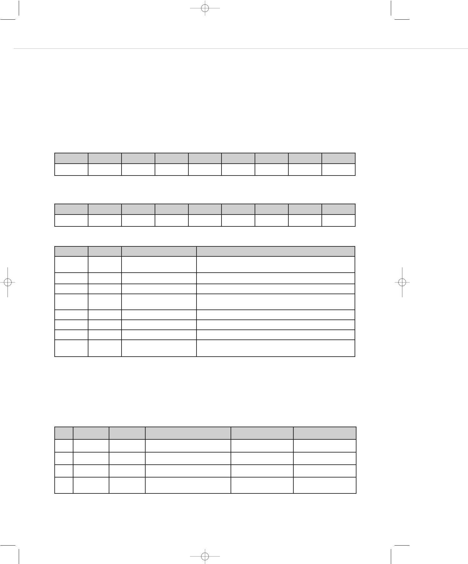
Empfangsbefehle
Folgende Befehle werden vom MIX 10 NG2 empfangen:
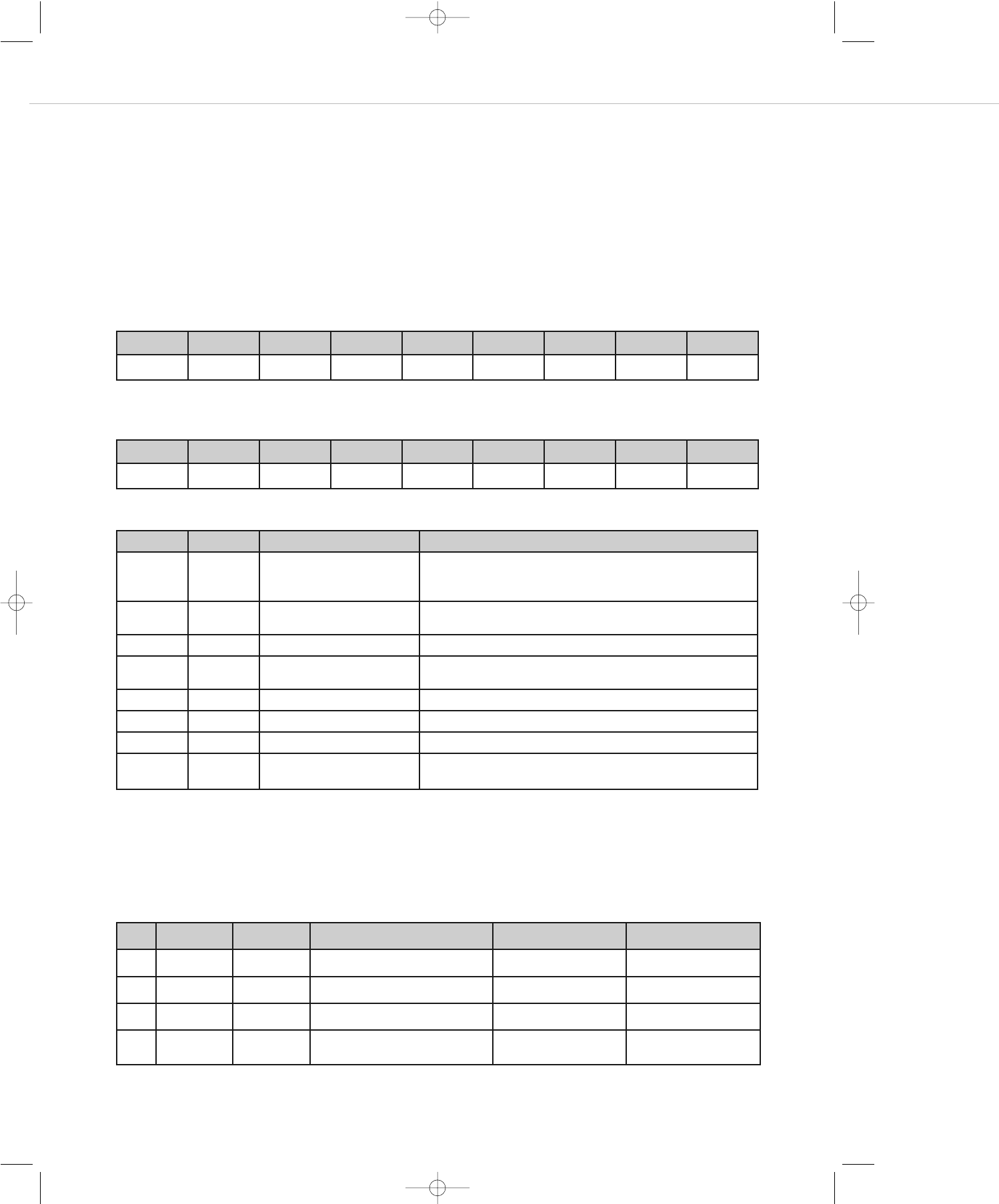
DLE STX Device No. Len Cmd Data DLE ETX Check Sum
0x10 0x02 0x00 (Cmd+Data) 0x10 0x03
DLE STX Device No. Len Cmd Data DLE ETX Check Sum
0x10 0x02 0x01 (Cmd+Data) 0x10 0x03
Gerät / Device –> PC
PC –> Device / Gerät
Hex Abk. Bezeichnung Bedeutung
0x10 DLE Data Link Escape Steuerzeichen, das anzeigt, dass eine festgelegte Anzahl an
nachfolgenden Zeichen eine andere Bedeutung - z. B. Steuer-
informationen - haben
0x02 STX Start of Text Markiert den Anfang der eigentlichen Nachricht und damit das Ende
des "Headers
0x01 Dev. No Device Number Gibt die Geräte-ID an
- Len Length Gibt die Befehlslänge (byte) des eigentlichen Befehls (Cmd+Data) an –
i.d.R 0x02 oder 0x03
-Cmd Command Siehe folgende Tabellen
Data Siehe folgende Tabellen
0x03 ETX End of Text Markiert das Ende der zu übertragenden Nachricht
-Check Sum Check sum XOR Kontroll- Byte zur Erkennung ob der Befehl richtig übertragen
wurde
Cmd Data0 Data1 Command Data0 Data1
A1 00~04 Select line source line 1 - 4 or none(0)
A2 00~4F 00~04 Set stereo volume to value “N” Nstereo no
A3 00~4F 10~15 Set mic volume to value “N” Nmic no
A6 00~1F
26Bit 6
00~04 Change stereo volume by “N”-steps
Higher or lower
N
0 = higher, 1 = lower
stereo
MIX10NG2_BA_DE_2008:MIX10NG_BA_DE 01.02.2008 10:29 Uhr Seite 12
MIX 10 NG2 – RS 232-Schnittstelle 13
deutsch
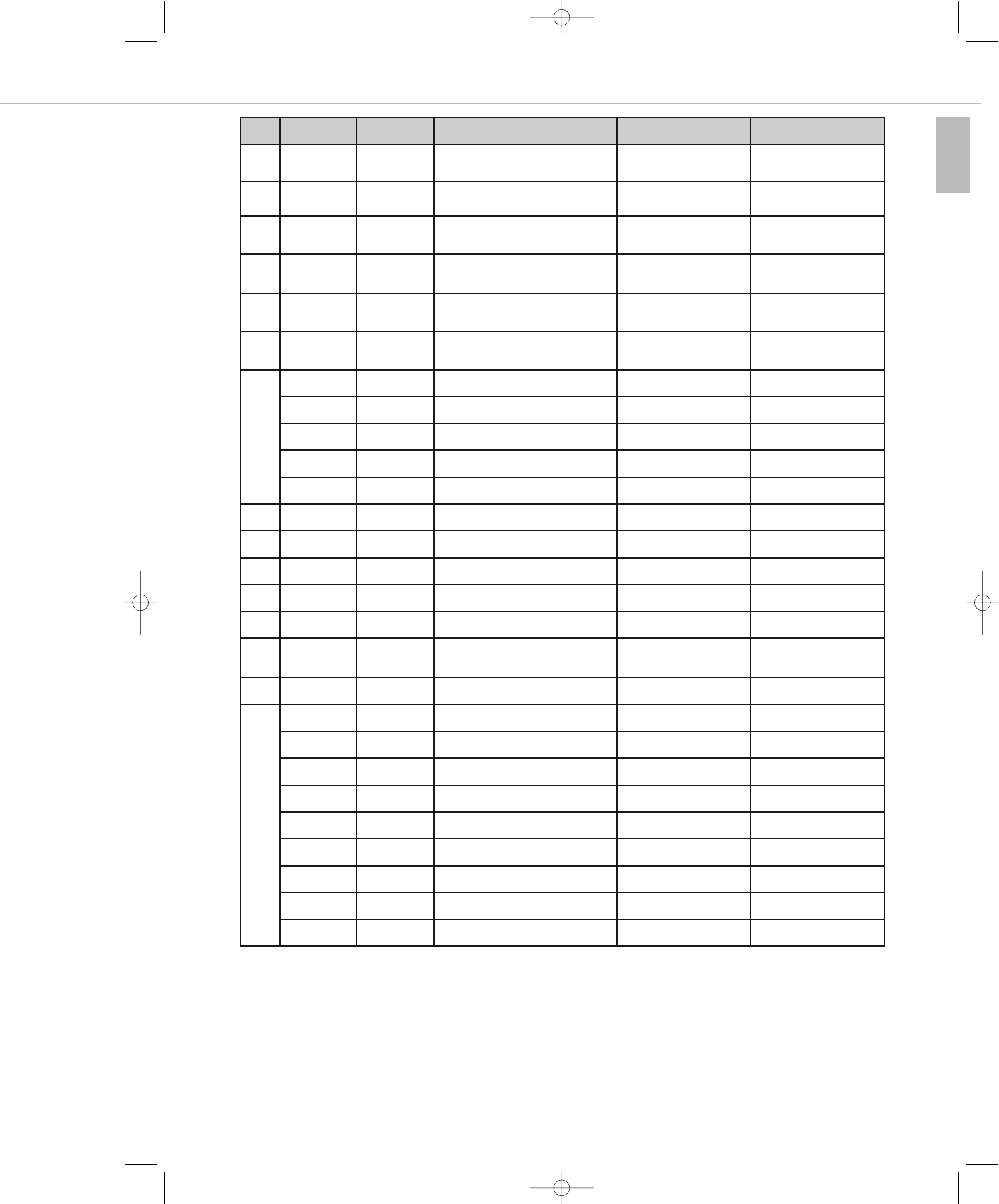
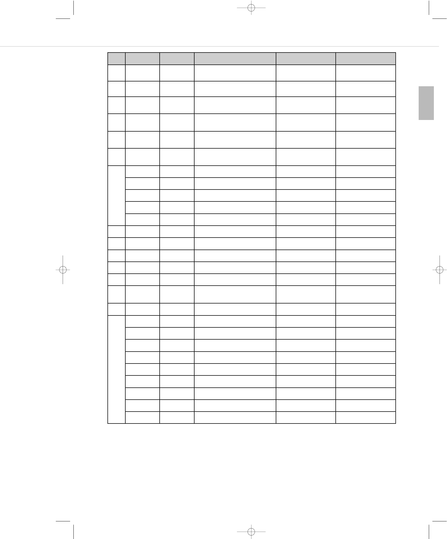
Cmd Data0 Data1 Command Data0 Data1
A7 00~1F
26Bit 6
10~15 Change mic volume by “N”-steps
Higher or lower
N
0 = higher, 1 = lower
mic no
A8 00~02 Ducking manually 02 = on
00 = off
A9 00~01 10~15 Mic ducking 01 = enabled
00 = disabled mic no
AA 00~01 01~02 Stereo ganged 01 = enabled
00 = disabled
01 = subgroup
02 = master
AB 00~03 00~01 Recall or save preset preset number 00 = recall
01 = save
AE 00~01 00~04,10~15 Mute channel 00= unmute
01 = mute stereo / mic no
AF 01 Inquiry select line source
02 00~04 Inquiry stereo volume stereo no
03 10~15 Inquiry mic volume mic no
06 01~02 Inquiry stereo ganged 01 = subgroup , 02 = master
07 00~04,10~15 Inquiry mute state stereo / mic no
B0 00~7F Fade-out speed speed value
B1 00~7F Fade-in speed speed value
B2 00~7F Ducking threshold threshold value
B3 00~4F Ducking attenuation attenuation value
B4 00~7F Ducking hold value
B7 00~03 Switch-on status preset 1/2/3/switch-off
status(0)
B8 00 Reset EEPROM
BF 00 Inquiry fade-out speed
01 Inquiry fade-in speed
02 Inquiry ducking threshold value
03 Inquiry ducking stereo reduction
04 Inquiry ducking hold
05 Inquiry ducking fade-out speed
06 Inquiry ducking fade-in speed
07 Inquiry start configuration
08 Inquiry programmed version
„10“ ~ „15“ steht für Kanäle MIC1~MIC6
„00“~ „04“ steht für die Kanäle LINE, SUB-L, SUB-R, MASTER-L,MASTER-R.
Lautstärke-Skalierung (hex):
00 ... 20 N x (-0,5 dB)
21 ... 40 N x (-1,0 dB) + 16,0 dB
41 ... 4E N x (-2,0 dB) + 80,0 dB
4F ... 7F -104 dB = mute
MIX10NG2_BA_DE_2008:MIX10NG_BA_DE 01.02.2008 10:29 Uhr Seite 13

MIX 10 NG2 – RS 232-Schnittstelle 14
Sendebefehle
Folgende Befehle werden vom MIX 10 NG2 gesendet:
„10“ ~ „15“ steht für Kanäle MIC1~MIC6.
„00“ ~ „04“ steht für die Kanäle LINE, SUB-L, SUB-R, MASTER-L,MASTER-R.
Eine Bestätigungsnachricht (Acknowledge) wird vom MIX 10 NG2 direkt nach Empfang einer Anforderung gesendet.
Beispiel:
Auswahl des CD-Line Eingangs
DLE STX Device No. Len Cmd Data DLE ETX Check Sum
10 02 01 02 A1 03 10 03 A0
Cmd Data0 Data1 Command Data0 Data1
C1 00~04 Line source selected line 1 - 4 or none(0)
C2 00~4F 00~04 Stereo volume currently adjusted
value “N”
N - value stereo no
C3 00~4F 10~15 Mic volume currently adjusted value
“N”
N - value mic no
C4 00~4F 00~04 Stereo volume now value “N” N - value stereo no
C5 00~4F 10~15 Mic volume now value “N” N - value mic no
C8 20Bit 0 Auto ducking 1 = on , 0 = off
21Bit 1 Ducking manually 1 = on , 0 = off
C9 00~01 10~15 Mic ducking 01 = enabled ,
00= disabled mic no
CA 00~01 01~02 Stereo ganged 01 = enabled ,
00= disabled
01 = subgroup,
02 = master
CB 00~03 00~01 Load or save preset 0-default / preset 1,2,3 00 = load , 01 = save
CE 00~01 00~04,10~15 Mute flag 1 = on , 0 = off stereo / mic
D0 00~7F Fade-out speed N - value
D1 00~7F Fade-in speed N - value
D2 00~7F Ducking threshold value N - value
D3 00~4F Ducking reduction N - value
D4 00~7F Ducking hold N - value
D7 00~03 Switch-on status preset 1/2/3/switch-off
status(0)
D8 Programmed version (V 1.0)
PC –> Device / Gerät
MIX10NG2_BA_DE_2008:MIX10NG_BA_DE 01.02.2008 10:29 Uhr Seite 14
MIX 10 NG2 – RS 232-Schnittstelle 15
deutsch
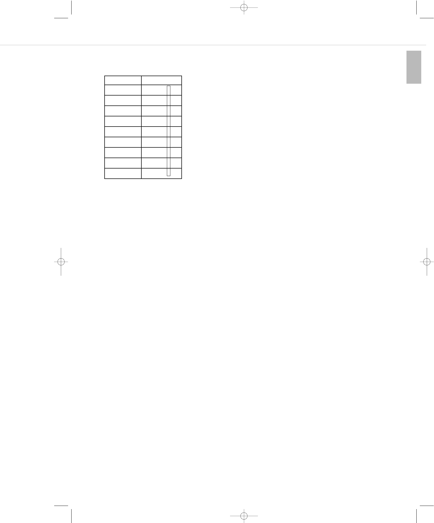
Checksumme
Die Checksumme resultiert aus einem vertikalen XOR Abgleich der einzelnen Befehlsbytes im Binärsystem. Für das auf der vorhergehenden
Seite gezeigte Beispiel ergibt sich die Checksumme wie folgt:
Änderungen vorbehalten.
Zahl hex Zahl Binär
10 0001 0000
02 0000 0010
01 0000 0001
02 0000 0010
A1 1010 0001
03 0000 0011
10 0001 0000
03 0000 0011
A0 1010 0000
MIX10NG2_BA_DE_2008:MIX10NG_BA_DE 01.02.2008 10:29 Uhr Seite 15

MIX 10 NG2 – Technische Daten 16
8. Technische Daten
Frequenzgang . . . . . . . . . . . . . . . . . . . . . . . . . . . 22 - 22.000 Hz (-3 dB)
Gain (Mic) . . . . . . . . . . . . . . . . . . . . . . . . . . . . . . 0dB – 56 dB
Klirrfaktor . . . . . . . . . . . . . . . . . . . . . . . . . . . . . . < 0,3% @ 1kHz, 6 dBu Output, max. gain
Signal-Rauschabstand . . . . . . . . . . . . . . . . . . . . . 93dB @ 1kHz, 15 dBu Output, 1% THD+N, max. gain
Mikrofoneingänge
Kopplung . . . . . . . . . . . . . . . . . . . . . . . . . . . . . . elektronisch symmetriert
Eingangsimpedanz . . . . . . . . . . . . . . . . . . . . . . . 600 Ω
Eingangspegel . . . . . . . . . . . . . . . . . . . . . . . . . . . max. 4 dBu @ 0,5% THD+N, min. Gain
Phantomspeisung . . . . . . . . . . . . . . . . . . . . . . . . 27 V, schaltbar
Anschluss . . . . . . . . . . . . . . . . . . . . . . . . . . . . . . abnehmbare Schraubklemmen je Eingang
Prioritätsschaltung . . . . . . . . . . . . . . . . . . . . . . . . Ducking-Funktion durch Mic 1 bzw. alle Mikrofoneingänge, -40 dB, intern abschaltbar
Stereo-Line-Eingänge
Kopplung . . . . . . . . . . . . . . . . . . . . . . . . . . . . . . unsymmetrisch
Eingangsimpedanz . . . . . . . . . . . . . . . . . . . . . . . 7 kΩ
Anschluss . . . . . . . . . . . . . . . . . . . . . . . . . . . . . . 2 x Cinch je Eingang
Stereo-Mix-Eingang
Kopplung . . . . . . . . . . . . . . . . . . . . . . . . . . . . . . unsymmetrisch
Eingangsimpedanz . . . . . . . . . . . . . . . . . . . . . . . 20 kΩ
Anschluss . . . . . . . . . . . . . . . . . . . . . . . . . . . . . . 2 x Cinch
Klangregelung
Tiefen . . . . . . . . . . . . . . . . . . . . . . . . . . . . . . . . . 40 Hz, ± 12 dB
Höhen . . . . . . . . . . . . . . . . . . . . . . . . . . . . . . . . . 13,5 kHz, ± 12 dB
Haupt-Ausgänge Stereo
Kopplung . . . . . . . . . . . . . . . . . . . . . . . . . . . . . . elektronisch symmetriert
Ausgangsimpedanz . . . . . . . . . . . . . . . . . . . . . . . 50 Ω
Max. Ausgangspegel . . . . . . . . . . . . . . . . . . . . . . 6,9 Veff (+19 dBu)
Anschluss . . . . . . . . . . . . . . . . . . . . . . . . . . . . . . 2 x 3-pol. Klemmanschluss
Kopplung . . . . . . . . . . . . . . . . . . . . . . . . . . . . . . unsymmetrisch
Ausgangssimpedanz . . . . . . . . . . . . . . . . . . . . . . 50 Ω
Max. Ausgangspegel . . . . . . . . . . . . . . . . . . . . . . 3,45 Veff (+13 dBu)
Anschluss . . . . . . . . . . . . . . . . . . . . . . . . . . . . . . 2 x Cinch
Sub-Ausgang
Kopplung . . . . . . . . . . . . . . . . . . . . . . . . . . . . . . elektronisch symmetriert
Ausgangsimpedanz . . . . . . . . . . . . . . . . . . . . . . . 50 Ω
Max. Ausgangspegel . . . . . . . . . . . . . . . . . . . . . . 6,9 Veff (+19 dBu)
Anschluss . . . . . . . . . . . . . . . . . . . . . . . . . . . . . . 2 x 3-pol. Klemmanschluss
Record-Ausgang (Mikrofonsumme Mono)
Kopplung . . . . . . . . . . . . . . . . . . . . . . . . . . . . . . unsymmetrisch
Ausgangsimpedanz . . . . . . . . . . . . . . . . . . . . . . . 50 Ω
Max. Ausgangspegel . . . . . . . . . . . . . . . . . . . . . . 3,45 Veff (+13 dBu)
Anschluss . . . . . . . . . . . . . . . . . . . . . . . . . . . . . . 2 x Cinch
PC-Anschluss. . . . . . . . . . . . . . . . . . . . . . . . . . . . RS-232
Netzspannung . . . . . . . . . . . . . . . . . . . . . . . . . . . 230 V AC
Abmessungen . . . . . . . . . . . . . . . . . . . . . . . . . . . 19"/1 HE (B x H x T / 483 x 44 x 135 mm)
Gewicht . . . . . . . . . . . . . . . . . . . . . . . . . . . . . . . 2,9 kg
MIX10NG2_BA_DE_2008:MIX10NG_BA_DE 01.02.2008 10:29 Uhr Seite 16
MIX 10 NG2 – Blockschaltbild 17
deutsch
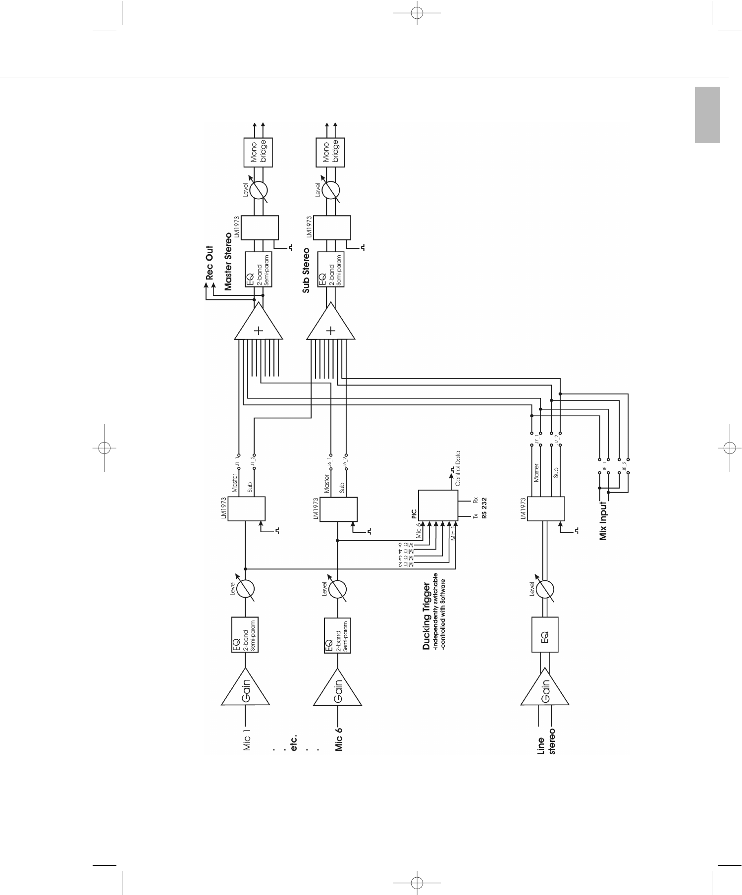
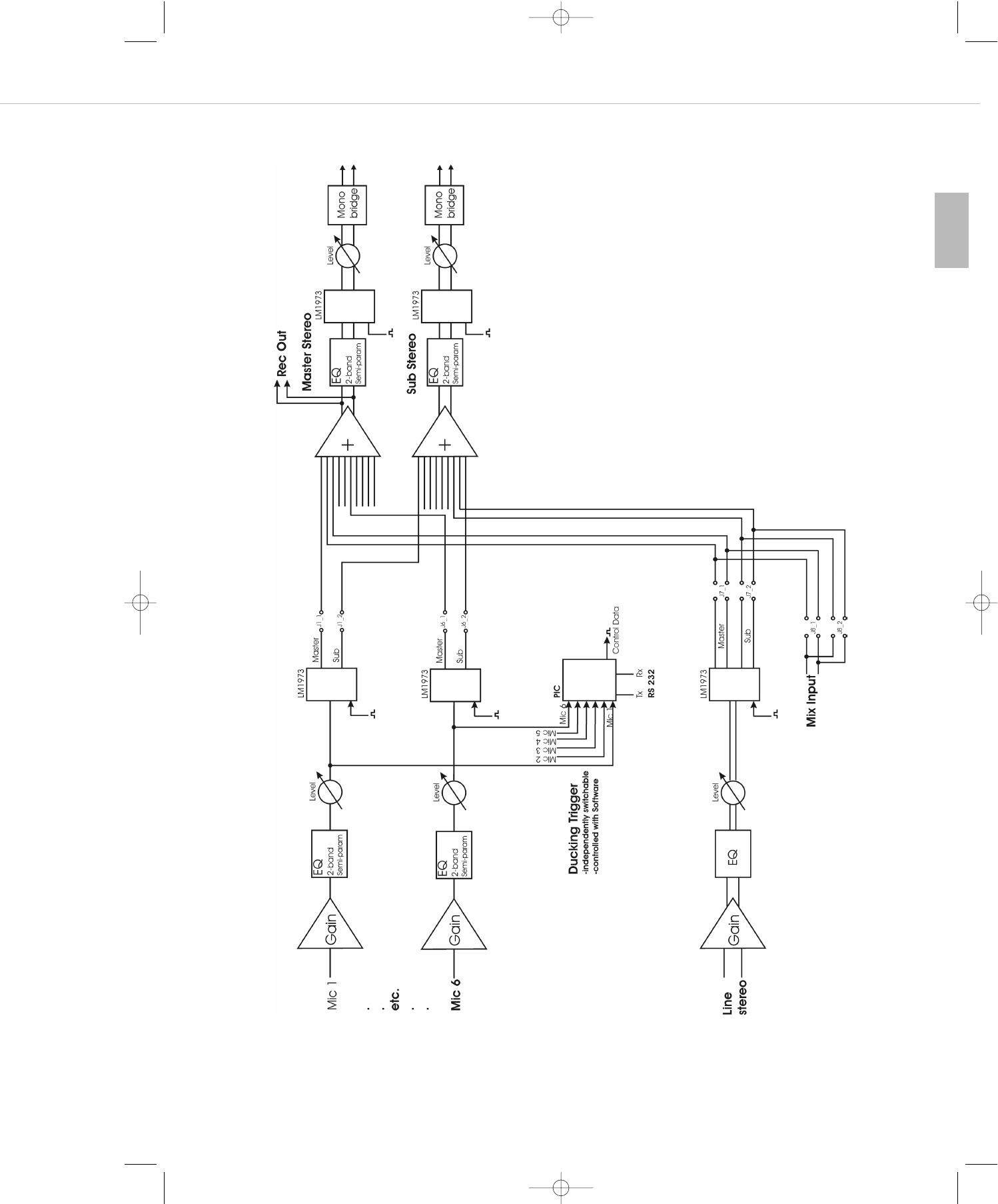
9. Blockschaltbild
MIX10NG2_BA_DE_2008:MIX10NG_BA_DE 01.02.2008 10:29 Uhr Seite 17

MIX10NG2_BA_DE_2008:MIX10NG_BA_DE 01.02.2008 10:29 Uhr Seite 18

MIX 10 NG2 – Contents 19
english
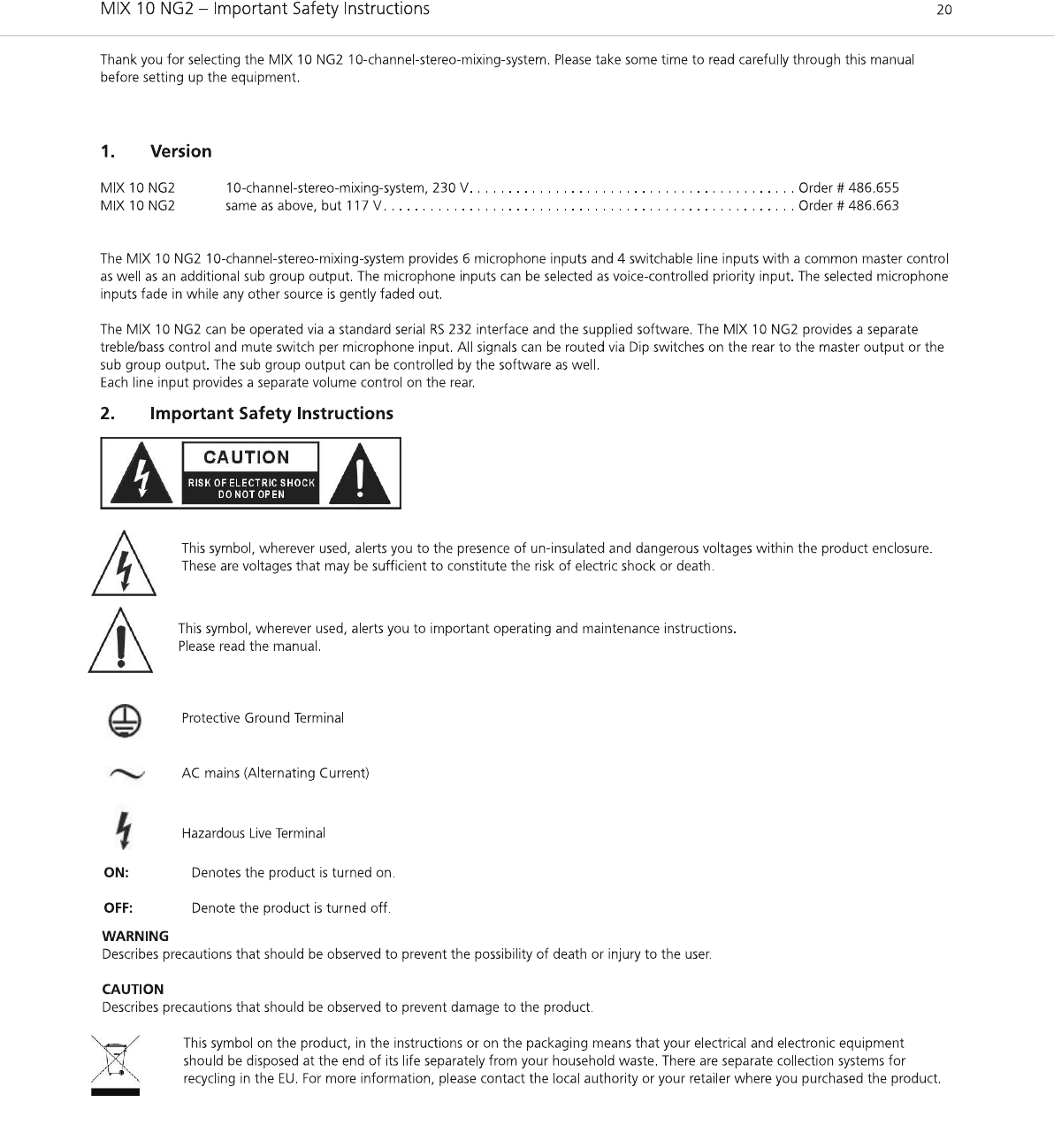
1. Version . . . . . . . . . . . . . . . . . . . . . . . . . . . . . . . . . . . . . . . . . . . . . . . . . . . . . . . . . . . . . . . . . . . . . . . . . . . . . . . . 20
2. Important Safety Instructions . . . . . . . . . . . . . . . . . . . . . . . . . . . . . . . . . . . . . . . . . . . . . . . . . . . . . . . . . . . . . . . 20
3. Controls and Indicators . . . . . . . . . . . . . . . . . . . . . . . . . . . . . . . . . . . . . . . . . . . . . . . . . . . . . . . . . . . . . . . . . . . . 22
4. Connections . . . . . . . . . . . . . . . . . . . . . . . . . . . . . . . . . . . . . . . . . . . . . . . . . . . . . . . . . . . . . . . . . . . . . . . . . . . . 23
4.1 Microphone Inputs . . . . . . . . . . . . . . . . . . . . . . . . . . . . . . . . . . . . . . . . . . . . . . . . . . . . . . . . . . . . . . . . . 23
4.1.1 Priority Control (“Prior”) . . . . . . . . . . . . . . . . . . . . . . . . . . . . . . . . . . . . . . . . . . . . . . . . . . . . . . . . . . . . . 23
4.2 Line Inputs. . . . . . . . . . . . . . . . . . . . . . . . . . . . . . . . . . . . . . . . . . . . . . . . . . . . . . . . . . . . . . . . . . . . . . . . 23
4.3 Mix Input. . . . . . . . . . . . . . . . . . . . . . . . . . . . . . . . . . . . . . . . . . . . . . . . . . . . . . . . . . . . . . . . . . . . . . . . . 23
4.4 Record Out . . . . . . . . . . . . . . . . . . . . . . . . . . . . . . . . . . . . . . . . . . . . . . . . . . . . . . . . . . . . . . . . . . . . . . . 23
4.5 Master Output. . . . . . . . . . . . . . . . . . . . . . . . . . . . . . . . . . . . . . . . . . . . . . . . . . . . . . . . . . . . . . . . . . . . . 23
4.6 Sub Group Output. . . . . . . . . . . . . . . . . . . . . . . . . . . . . . . . . . . . . . . . . . . . . . . . . . . . . . . . . . . . . . . . . . 24
4.7 Mains . . . . . . . . . . . . . . . . . . . . . . . . . . . . . . . . . . . . . . . . . . . . . . . . . . . . . . . . . . . . . . . . . . . . . . . . . . . 24
5. Allocation of the Input Channels via Dip Switches . . . . . . . . . . . . . . . . . . . . . . . . . . . . . . . . . . . . . . . . . . . . . . . . 24
6. Setting up. . . . . . . . . . . . . . . . . . . . . . . . . . . . . . . . . . . . . . . . . . . . . . . . . . . . . . . . . . . . . . . . . . . . . . . . . . . . . . 24
7. Remote Control via RS 232 . . . . . . . . . . . . . . . . . . . . . . . . . . . . . . . . . . . . . . . . . . . . . . . . . . . . . . . . . . . . . . . . . 24
7.1 Software Installation . . . . . . . . . . . . . . . . . . . . . . . . . . . . . . . . . . . . . . . . . . . . . . . . . . . . . . . . . . . . . . . . 24
7.2 Connection . . . . . . . . . . . . . . . . . . . . . . . . . . . . . . . . . . . . . . . . . . . . . . . . . . . . . . . . . . . . . . . . . . . . . . . 24
7.3 Operation . . . . . . . . . . . . . . . . . . . . . . . . . . . . . . . . . . . . . . . . . . . . . . . . . . . . . . . . . . . . . . . . . . . . . . . . 25
7.3.1 Control Panel. . . . . . . . . . . . . . . . . . . . . . . . . . . . . . . . . . . . . . . . . . . . . . . . . . . . . . . . . . . . . . . . . . . . . . 25
7.3.2 Preferences . . . . . . . . . . . . . . . . . . . . . . . . . . . . . . . . . . . . . . . . . . . . . . . . . . . . . . . . . . . . . . . . . . . . . . . 26
7.3.3 COM . . . . . . . . . . . . . . . . . . . . . . . . . . . . . . . . . . . . . . . . . . . . . . . . . . . . . . . . . . . . . . . . . . . . . . . . . . . . 27
7.4 Specifications of the RS 232 Interface . . . . . . . . . . . . . . . . . . . . . . . . . . . . . . . . . . . . . . . . . . . . . . . . . . . 28
8. Technical Specifications . . . . . . . . . . . . . . . . . . . . . . . . . . . . . . . . . . . . . . . . . . . . . . . . . . . . . . . . . . . . . . . . . . . . 32
9. Block Diagram . . . . . . . . . . . . . . . . . . . . . . . . . . . . . . . . . . . . . . . . . . . . . . . . . . . . . . . . . . . . . . . . . . . . . . . . . . 33
EC-Declaration of Conformity. . . . . . . . . . . . . . . . . . . . . . . . . . . . . . . . . . . . . . . . . . . . . . . . . . . . . . . . . . . . . . . . . . 34
MIX10NG2_BA_DE_2008:MIX10NG_BA_DE 01.02.2008 10:29 Uhr Seite 19
NOTE:This equipment has been tested and found to comply with the limits for a Class B digital device,
pursuant to Part 15 of the FCC Rules. These limits are designed to provide reasonable protection against
harmful interference in a residential installation. This equipment generates, uses and can radiate radio
frequency energy and, if not installed and used in accordance with the instructions, may cause harmful
interference to radio communications. Howerver, there is no guarantee that interference will not occur in
a particular installation. If this equipment does cause harmful interference to radio or television reception.
which can be determined by turning the equipment off and on, the user is encouraged to try to correct the
interference by one or more of the following measures:
--Reorient or relocate the receiving antenna.
--Increase the separation between the equipment and receiver.
--Connect the equipment into an outlet on a circuit different form that to which the receiver is connected.
--consult the dealer or an experienced radio/TV technician for help.

MIX 10 NG2 – Important Safety Instructions 21
english
General
• READ the Operating Instructions.
• KEEP these Operating Instructions safe.
• COMPLY with the Operating and Safety instructions listed.
• Always install in accordance with the manufacturer’s instructions.
• Only use attachments/accessories specified by the manufacturer.
Exemption from liability
• beyerdynamic GmbH & Co. KG will not be liable if any damage, injury or accident occurs due to negligent,
incorrect or inappropriate operation of the product.
Location
• The equipment must be set up so that the plug connector is easily accessible.
• If you transport the equipment to another location take care to ensure that it is adequately secured and can never be damaged by being
dropped or by impacts on the equipment.
Fire hazard
• Do not place heavy objects on the power cord. This could cause electric shock or fire.
• Never place naked flames near the equipment.
Humidity / heat sources
• Never expose the equipment to rain or a high level of humidity. For this reason do not install it in the immediate vicinity of swimming
pools, showers, damp basement rooms or other areas with unusually high atmospheric humidity.
• Never place objects containing liquid (e.g. vases or drinking glasses) on the equipment. Liquids in the equipment could cause a short
circuit.
• Never install and operate the equipment close to radiators, lighting equipment or other heat generating equipment.
Ventilation
• This equipment needs adequate ventilation. Do not cover ventilation grilles. If the heat it generates cannot be dissipated, the equipment
could be damaged or flammable materials in its immediate vicinity could be ignited. Take care to ensure that the air can circulate freely
through the ventilation grilles and keep flammable materials away.
• Do not insert objects into the ventilation grilles or other openings. You could damage the equipment and/or injure yourself.
Connection
• The equipment must be connected to a mains socket that has an earth contact.
• Always run all cables so that they cannot be damaged or severed by sharp objects.
• Lay all connection cables so that they do not present a trip hazard.
• Protect the power cord and plug from any physical stress to avoid risk of electric shock.
• Whenever working on the equipment switch off all inputs and outputs to the power supply.
• Check whether the connection figures comply with the existing mains supply. Serious damage could occur due to connecting the system
to the wrong power supply. An incorrect mains voltage could damage the equipment or cause an electric shock.
• If the plug does not fit your AC outlet seek advice from a qualified electrician.
• If there is a thunderstorm or you will not be using the equipment for a lengthy period of time, remove it from the mains supply.
• If you connect defective or unsuitable accessories, the equipment could be damaged. Only use connection cables available from or
recommended by beyerdynamic. If you use cables you have made up yourself, all claim to warranty is null and void.
• If the equipment causes a blown fuse or a short circuit, disconnect it from the mains and have it checked and repaired.
• Do not hold the mains cable with wet hands. There must be no water or dust on the contact pins. In both cases you could receive an
electric shock.
• The mains cable must be firmly connected. If it is loose there is a fire hazard.
• Always pull out the mains cable from the mains and/or from the equipment by the plug - never by the cable. The cable could be damaged
and cause an electric shock or fire.
• Do not use the equipment if the mains plug is damaged.
• Never cut internal or external Ground wires. Likewise, never remove Ground wiring from the Protective Ground Terminal.
• Do not remove Ground connections.
• Do not tamper with the power cord or plug. These are designed for your safety.
• Before turning the product ON, make sure that it is connected to Ground. This is to prevent the risk of electric shock.
Maintenance
• For safety, keep product clean and free from dust.
• Only clean the equipment with a slightly damp or dry cloth. Never use solvents such a Benzol or Alcohol as these damage the surface.
Trouble shooting and servicing
• Do not open the equipment without authorisation. You could receive an electric shock.
• No user serviceable parts inside.
• Refer all servicing to qualified service personnel only
Electromagnetic Compatibility
The MIX 10 NG2 can be used in following electromagnetic environment: residential, commercial and light industrial, urban outdoors.
In order to comply with the requested limits for electromagnetic compatibility the maximum length for cables shall not exceed:
1) Audio in 3 m
2) Audio output 10 m
3) RS 232 3 m
4) REC out 1 m
5) REC in 1 m
MIX10NG2_BA_DE_2008:MIX10NG_BA_DE 01.02.2008 10:29 Uhr Seite 21
*MIX 10 NG2, the peak inrush current is 157mA
*MIX 10 NG2, under the EM disturbance, the ratio of signal-noise may be changed above 10dB.
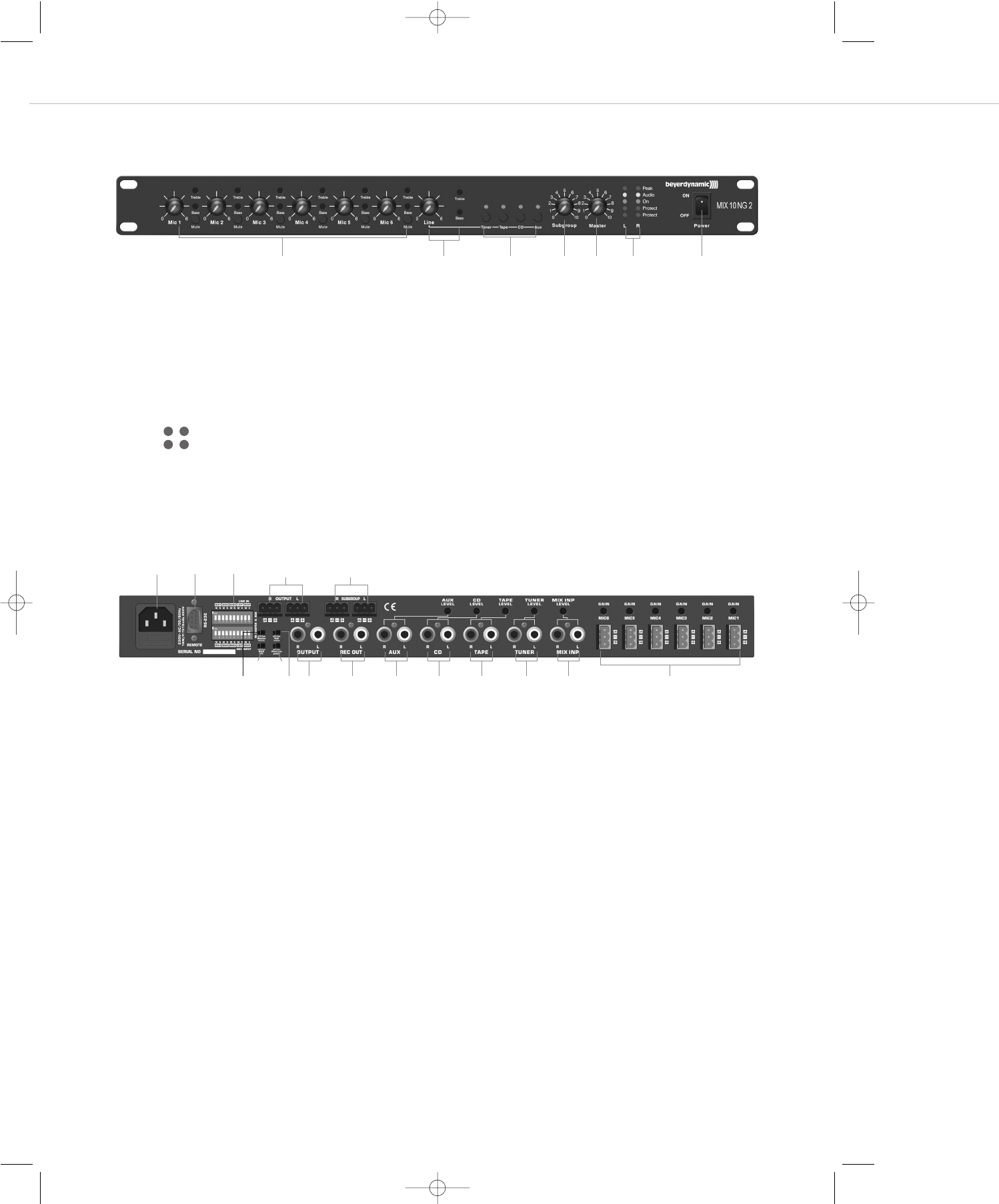
MIX 10 NG2 – Controls and Indicators 22
(1) Volume control microphone inputs (Mic 1 to Mic 6) with treble, bass controls and mute
(2) Volume control Line to set the level of CD, tape, tuner or Aux with treble and bass controls
(3) Input selection control for active Line input (CD, Tape, Tuner, Aux) and status LEDs
(4) Subgroup - volume control
(5) Master - volume control
(6) LEDs for left (L) and right (R) channel
Peak - Red LED is illuminated, when the peak of a signal occurs
Audio - Yellow LED is illuminated, when the output signal is present with 0 dB
On - Green LED is illuminated, when the device is switched on
Protect - Red LEDs for monitoring the balanced Master outputs (8)
The upper LEDs represent the positive output signal
The lower LEDs represent the negative output signal
2 or 3 is illuminated when a short circuit against ground occurs (Pin 1).
2 and 3 are illuminated simultaneously when a short circuit between Pin 2 and 3 occurs
(7) Mains switch
22
33
LR
Rear view
(8) Master Output R + L, 3-pin terminals, balanced
(9) Sub Group R + L, 3-pin terminals, balanced
(10) Mains supply (230 V/115 V) with fuse (315 mA/T / 500 mA/T))
(11) RS 232 interface, 9-pin Sub D, male
(12) Ground Lift to separate operating ground from mains ground. The ground lift is activated when the switch is switched to the right.
(13) Phantom Power – Off/On to activate or deactivate a phantom power of 27 volts when using condenser microphones.
(14) Master Mono to bridge the master outputs into a mono operation, stereo line sources are in mono at the master L/R outputs
(15) Sub Mono to bridge the sub outputs into a mono operation, stereo line sources are in mono at the sub group L/R outputs
(16) Dip switches to allocate the input channels to the master output (M) or sub group output (S). If the Dip switch is switched to the top,
the input channel is routed to the appropriate output.
(17) Master Output, +6 dB, master output R/L unbalanced, RCA
(18) REC - Record ouput L/R for the microphone master
(19) Aux input with separate volume control
(20) CD input with separate volume control
(21) Tape input with separate volume control
(22) Tuner input with separate volume control
(23) MIX INP - Stereo input with separate volume control for the connection of mixing consoles or more MIX 10 NG2
(24) MIC 1 - MIC 6 - Electronically balanced microphone inputs with gain control (input sensitivtity), 3-pin terminals
3. Controls and Indicators
Front view
(1) (3) (6)(4) (5) (7)(2)
(8) (9)(10) (11)
(12) (13)
(17)(15)(14) (18) (19) (20) (21) (22) (23) (24)
(16)
MIX10NG2_BA_DE_2008:MIX10NG_BA_DE 01.02.2008 10:30 Uhr Seite 22

MIX 10 NG2 – Connections 23
english
4. Connections
4.1 Microphone Inputs
On the rear of the MIX 10 NG 2 there are six microphone inputs (24) with removable terminals. The connection is balanced. For each input
the gain can be adjusted on the rear (0 - +55 dB). The input volume is adjusted with the volume controls (1) on the front or via the supplied
software. The microphone inputs can be selected for the priority function by using the supplied software (refer to chapter “4.1.1 Priority
switching”).
Warning:
A phantom power of +27 V (13) can be activated for all microphone inputs. If you connect devices with unbalanced outputs,
deactivate the phantom power or add a coupling capacitor.
4.1.1 Priority Control (“Prior”)
The priority of the privileged microphone inputs is voice-controlled (priority function). The priority control is available for all microphone
inputs and selected via the supplied software. All sources without selected priority function are gently faded out. The fade-out depth and the
speed of the fade-out and fade-in are selected with the software.
The fade-out is effected by talking into a microphone which is connected to one of the privileged microphone inputs. The MIX 10 NG2 is
delivered with the priority function being deactivated. If you want to use the priority function, activate it via the software as described in the
chapter “7.3.1 Control Panel”.
4.2 Line Inputs
Four separate line inputs (RCA phono) are on the rear of the MIX 10 NG2. One of these four line inputs can be selected with the appropriate
input selection control (3). The inputs are unbalanced and suitable for the connection of stereo devices. The input gain can be adjusted for
each input on the rear (Level). The line master volume is adjusted with the volume control (2) on the front or via the supplied software.
You can select the sources by using the buttons on the front or the software and the RS 232 connection.
4.3 Mix Input
The mix input (RCA phono) (23) is on the rear of the unit. The connection is unbalanced and suitable for stereo sound sources. This input is
suitable for the connection of more MIX 10 NG2 or mixing consoles.
The input gain (Level) for the mix input can be adjusted on the rear of the unit. This input is not affected by the line volume control.
4.4 Record Output
The record output (18) is unbalanced (0 dB). It is used for the connection of recording devices. The signal to be recorded is the master of the
microphone and line inputs before the sound and master volume control.
4.5 Master Output
The master output (8), +6 dBu, is a balanced output (3-pin terminals) for the connection to an external output amplifier. Here are all microphone
and line signals as a master which are routed via the Dip switches to the master output. The master output (8) is suitable when using long
cables. The master output (L/R) is adjusted with the volume control (5) on the front or via the supplied software.
The master output (17), 0 dBu, is an unbalanced output (stereo RCA) serving as an additional auxiliary output. It is parallel to the master
output (8). The master output (17) is suitable when using short cables, and can be connected to the input of a hi-fi amplifier.
MIX10NG2_BA_DE_2008:MIX10NG_BA_DE 01.02.2008 10:30 Uhr Seite 23

MIX 10 NG2 – Setting up 24
4.6 Sub Group Output
The sub group output (9), +6 dBu, is a balanced output (3-pin terminals) for the connection to an external output amplifier. Here are all
microphone and line signals as a master which are routed via the Dip switches to the sub group output. The sub group output (L/R) is adjusted
with the volume control (4) on the front or via the supplied software. The sub group output (9) is suitable for using long cables.
4.7 Mains
The power cable is connected to the mains (10). When you connect the device to the mains make sure that the mains voltage of the
MIX 10 NG2 corresponds to the local mains voltage.
5. Allocation of the Input Channels via Dip Switches
The Dip switches are used to allocate the input channels to the master output (M) or sub group output (S). If the Dip switch is set to the top,
the input channels is routed to the approriate output. This allows allocating separate signals to the different output zones (sub group (S) /
Master (M)).
6. Setting up
After all connections have been made (mains, microphone etc.), follow these steps to set up the system:
1. Reduce the gain (to minimum) of the amplifier/power amplifier connected to the MIX 10 NG2 and switch it off.
2. Set all volume controls on the front to the very right (maximum).
3. Turn on the MIX 10 NG2 with the on/off switch (7).
4. Speak at an appropriate distance into the microphone connected first and open the gain control on the rear until the audio LED (6) will
illuminate clearly when speaking up.
5. Repeat this procedure with all connected microphones.
6. Set all volume controls on the front into a 3/4 opened position.
7. Turn on the connected power amplifier and increase its input gain until the desired volume is achieved.
8. Fix this setting of the power amplifier. The fine tuning can be done with the control on the front of the MIX 10 NG2.
7. Remote Control via RS 232
To operate and configure the MIX 10 NG2 via a PC or media control system, the MIX 10 NG2 is equipped with an RS 232 connection
(9-pin Sub D, male).
7.1 Software Installation
• The supplied software serves for the configuration and remote control of the MIX 10 NG2.
• The software operates under Windows®XP / Vista. Put the CD into the CD drive and start the setup. Follow the instructions on the
screen.
7.2 Connection
• Connect the remote connection (11) with a standard RS 232 connecting cable to the serial RS 232 interface of your PC.
• Carefully select the cable length of the RS 232 connection. Inefficient PC interfaces and poor cables can considerably affect the
communication / performance.
MIX10NG2_BA_DE_2008:MIX10NG_BA_DE 01.02.2008 10:30 Uhr Seite 24
MIX 10 NG2 – Operation 25
english
7.3 Operation
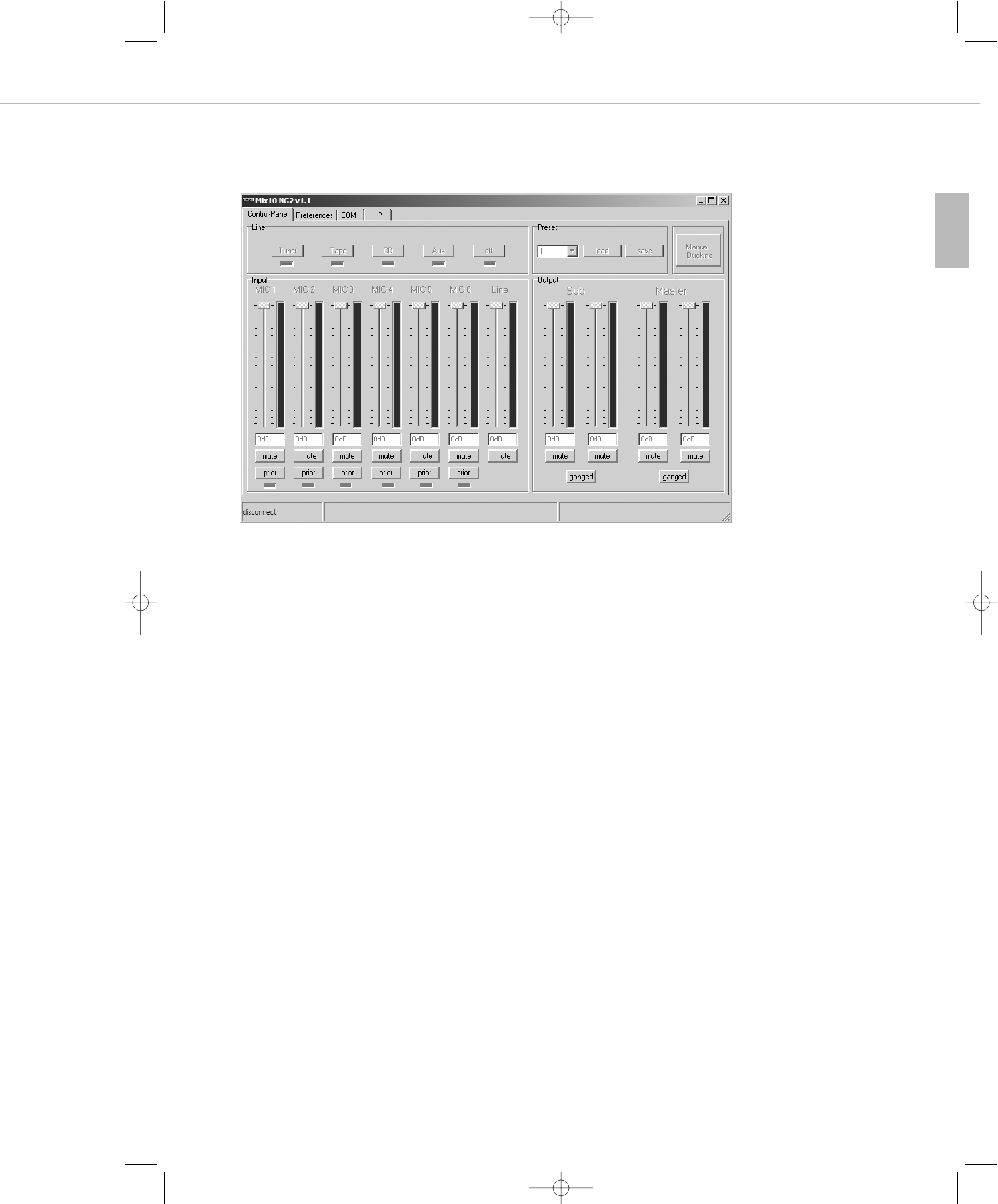
7.3.1 Control Panel
When you start the “MIX 10 NG2” program, the user interface “Control panel” is opened.
Here you can operate the most important volume controls and switching functions:
Line field
In the “Line” field you can select the line source connected to the MIX 10 NG2 by selecting the corresponding button “Tuner”, “Tape”,
“CD”, “Aux”. If you select the “off” button, you switch off all line sources.
The LEDs below the buttons indicate the selected line source of the MIX 10 NG2. Changes at the MIX 10 NG2 itself are also displayed.
Input
There is one fader and mute button for each input channel. In addition to that, the microphone input channels provide a “Prior” button and
an LED.
Using the fader you can control the input volume of individual microphone input channels and the volume of the selected line signal in dB.
With the appropriate mute button you can mute the respective channel. You can directly enter the attenuation values in dB into the window.
If the “Prior” button is activated for one or several microphone channels, they are in a priority switching. After setting more parameters
(chapter 7.3.2) the selected channels prompt an attenuation of the other input channels when speaking. This can be used for instance for
attenuating background music in stores during announcements.
Output
For the stereo master outputs “Master” and “Sub” there are two separate controls for the left and right channels with appropriate mute
buttons. This enables the control of the master signals which are routed to the appropriate channel via the Dip switches. With the “ganged”
button the channels can be combined when there is no different volume control for the left and right channel desired. With one control you
can operate the whole master or sub group volume.
Manual Ducking
Here you can manually prompt the attenuation of the channel without priority. Normally, this is done for testing purposes.
Preset
The internal memory of the Mix 10 NG2 allows storing up to 3 presets. One preset stores all settings which can be selected with the software
such as volume settings, priority switching and so on.
How to store presets:
1. Set all software settings as desired.
2. Select the desired preset (1, 2 or 3) with the drop-down menu in the “Preset” field.
3. Select the “save” button.
How to load presets:
1. Select the desired preset (1, 2 or 3) from the drop-down menu in the “Preset” field.
2. Select the “load” button.
MIX10NG2_BA_DE_2008:MIX10NG_BA_DE 01.02.2008 10:30 Uhr Seite 25
MIX 10 NG2 – Operation 26
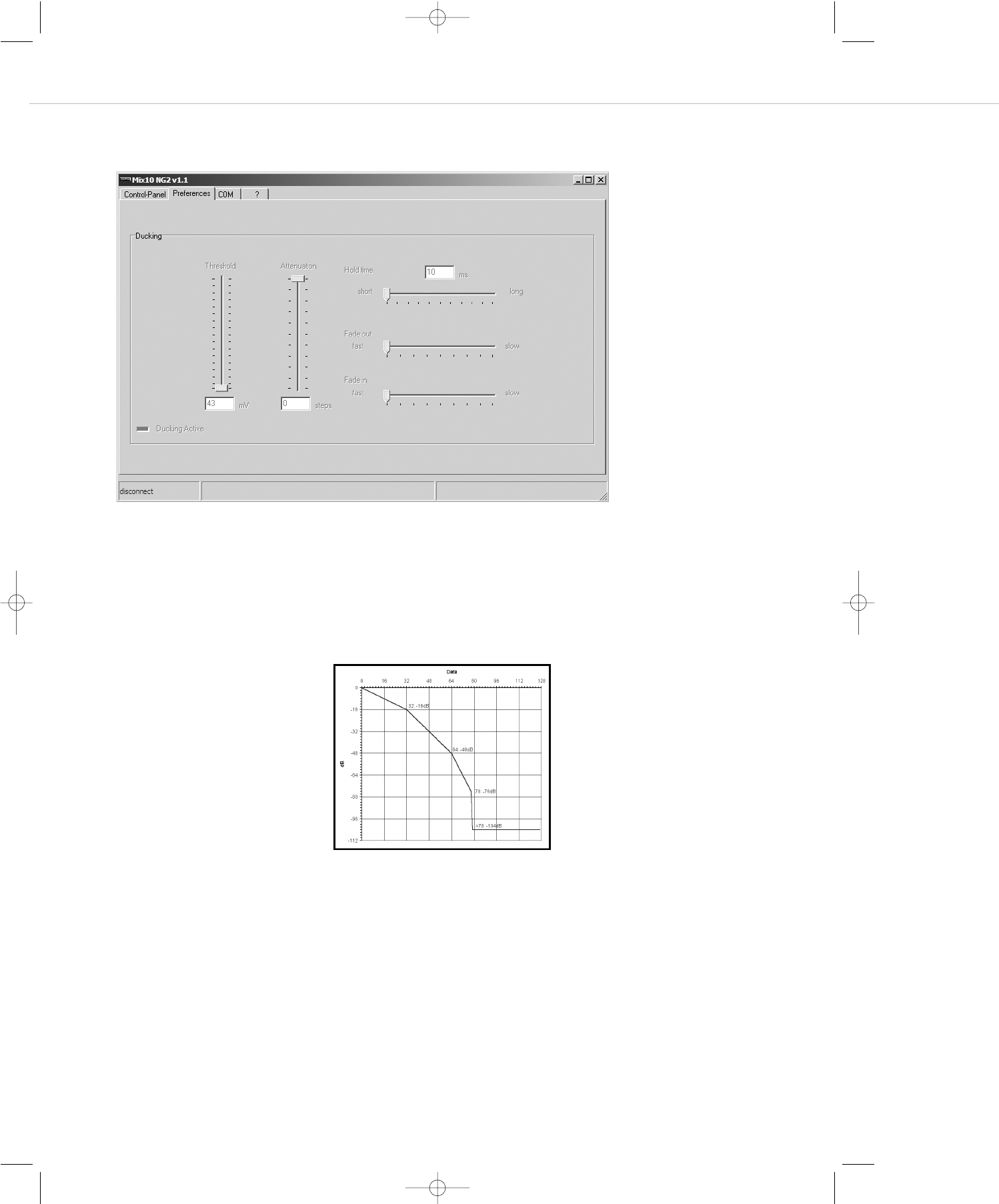
7.3.2 Preferences
In this tab all settings which are needed for the ducking function in the “prior” mode are selected.
Threshold
Here you can adjust the sensitivity of the voice activation in the priority mode. The lower the control, the lower the input level of the micro-
phone in priority mode to activate the attenuation. This means you select at which volume you have to speak into the microphone to activate
the ducking function (level reduction).
If the ducking function does not work properly even when the threshold has been set to minimum, the microphone input sensitivity (gain)
must be increased at the rear of the MIX 10 NG2.
Attenuation
Here you can select how deep the signal without priority is reduced when it is faded out.
Hold time
With the “hold time” control you can adjust the time until the previously reduced signal is faded in again. This time period should not be
selected too short.
Fade out / fade in
You can adjust how fast or slow the audio signal after exceeding the threshold level is faded out or in. The fade out time should be short to avoid
losing the first syllable in announcements. The fade in time should be longer so that a gentle fade in of background music for instance is achieved.
The adjustable values are:
0 to -16 dB in 0.5 dB steps
-16 to -48 dB in 1.0 dB steps
-48 to -76 dB in 2.0 dB steps
-104 dB mute
MIX10NG2_BA_DE_2008:MIX10NG_BA_DE 01.02.2008 10:30 Uhr Seite 26
MIX 10 NG2 – Operation 27
english
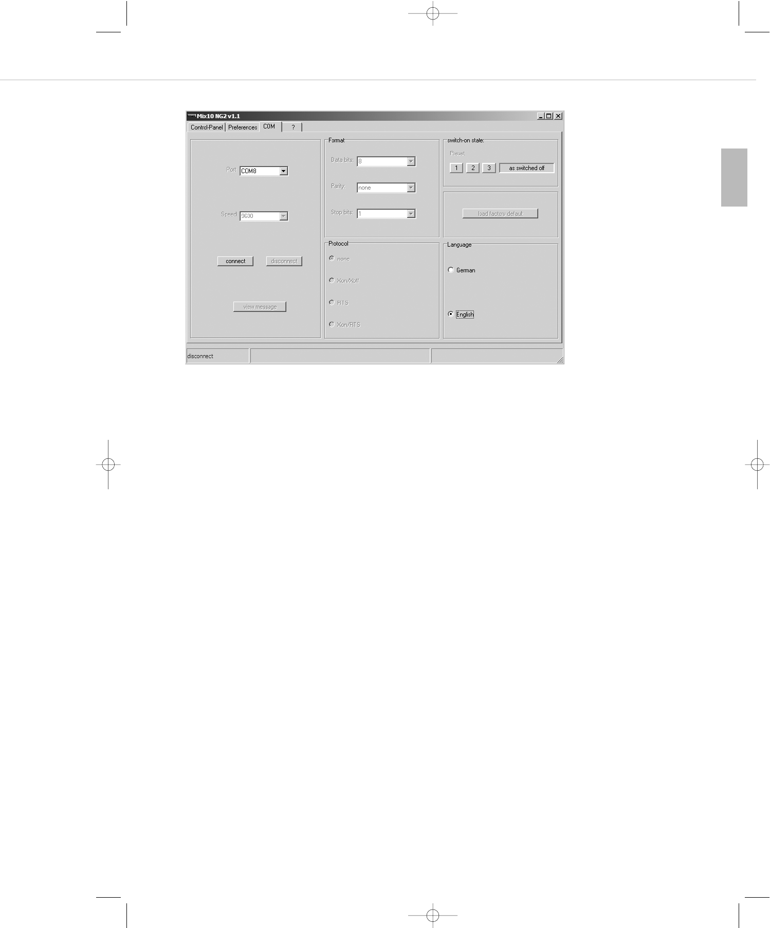
7.3.3 COM
In the “Port” menu you can activate the desired COM port to which the MIX 10 NG2 is to be connected. Parameters such as speed,
format and protocol are for your information and cannot be affected. Use the “connect” button to establish a COM connection between
MIX 10 NG2 and PC.
Switch-on state
Here you can enter the switch-on state of the MIX 10 NG2. You can select one of the previously saved presets. After turning on, the MIX 10
NG2 will load the settings of the selected preset 1, 2 or 3. Alternatively, you can save the state when the device was turned off by selecting
the “as switched off” button.
Load factory default
The MIX 10 NG2 is reset to the delivery state. The current settings are replaced by factory settings.
Warning: All saved presets and settings are lost!
Language
You can select if the menu is in English or German.
View message
Messages received or sent by the MIX 10 NG 2 are displayed in a pop-up window.
MIX10NG2_BA_DE_2008:MIX10NG_BA_DE 01.02.2008 10:30 Uhr Seite 27
MIX 10 NG2 – RS 232 Interface 28
7.4 Specifications of the RS 232 Interface
Speed 9600 Baud
Data format 1 start bit, 8 data bits, 1 stop bit, no parity
Handshake none
Sub-D 9 Pin 2 = Rx
Pin 3 = Tx
Pin 5 = GND
The data exchange between the MIX 10 NG2 and the superior control is done via two-byte commands which are integrated in a data packet
with subsequent check sum.
The structure of the commands is as follows:
Received Commands
The following commands are received from the MIX 10 NG2:
DLE STX Device No. Len Cmd Data DLE ETX Check Sum
0x10 0x02 0x00 (Cmd+Data) 0x10 0x03
DLE STX Device No. Len Cmd Data DLE ETX Check Sum
0x10 0x02 0x01 (Cmd+Data) 0x10 0x03
Device –> PC
PC –> Device
Hex Abbrev. Designation Description
0x10 DLE Data Link Escape Control character, which indicates that a defined number of following
characters has another meaning e.g control information
0x02 STX Start of Text Designates the start of the actual message and the end of the “Header”
0x01 Dev. No Device Number States the device ID
- Len Length States the length (byte) of the actual command (Cmd+Data) – normally
0x02 or 0x03
-Cmd Command Refer to the following tables
Data Refer to the following tables
0x03 ETX End of Text Designates the end of the message to be transmitted.
-Check Sum Check Sum XOR control byte to recognise if the command has been transmitted
correctly
Cmd Data0 Data1 Command Data0 Data1
A1 00~04 Select line source line 1 - 4 or none(0)
A2 00~4F 00~04 Set stereo volume to value “N” Nstereo no
A3 00~4F 10~15 Set mic volume to value “N” Nmic no
A6 00~1F
26Bit 6
00~04 Change stereo volume by “N”-steps
Higher or lower
N
0 = higher, 1 = lower
stereo
MIX10NG2_BA_DE_2008:MIX10NG_BA_DE 01.02.2008 10:30 Uhr Seite 28
MIX 10 NG2 – RS 232 Interface 29
english
Cmd Data0 Data1 Command Data0 Data1
A7 00~1F
26Bit 6
10~15 Change mic volume by “N”-steps
Higher or lower
N
0 = higher, 1 = lower
mic no
A8 00~02 Ducking manually 02 = on
00 = off
A9 00~01 10~15 Mic ducking 01 = enabled
00 = disabled mic no
AA 00~01 01~02 Stereo ganged 01 = enabled
00 = disabled
01 = subgroup
02 = master
AB 00~03 00~01 Recall or save preset preset number 00 = recall
01 = save
AE 00~01 00~04,10~15 Mute channel 00= unmute
01 = mute stereo / mic no
AF 01 Inquiry select line source
02 00~04 Inquiry stereo volume stereo no
03 10~15 Inquiry mic volume mic no
06 01~02 Inquiry stereo ganged 01 = subgroup , 02 = master
07 00~04,10~15 Inquiry mute state stereo / mic no
B0 00~7F Fade-out speed speed value
B1 00~7F Fade-in speed speed value
B2 00~7F Ducking threshold threshold value
B3 00~4F Ducking attenuation attenuation value
B4 00~7F Ducking hold value
B7 00~03 Switch-on status preset 1/2/3/switch-off
status(0)
B8 00 Reset EEPROM
BF 00 Inquiry fade-out speed
01 Inquiry fade-in speed
02 Inquiry ducking threshold value
03 Inquiry ducking stereo reduction
04 Inquiry ducking hold
05 Inquiry ducking fade-out speed
06 Inquiry ducking fade-in speed
07 Inquiry start configuration
08 Inquiry programmed version
“10” ~ “15” represent the channels MIC1~MIC6
“00”~ “04” represent the channels LINE, SUB-L, SUB-R, MASTER-L,MASTER-R.
Volume scale (hex):
00 ... 20 N x (-0.5 dB)
21 ... 40 N x (-1.0 dB) + 16.0 dB
41 ... 4E N x (-2.0 dB) + 80.0 dB
4F ... 7F -104 dB = mute
MIX10NG2_BA_DE_2008:MIX10NG_BA_DE 01.02.2008 10:30 Uhr Seite 29
MIX 10 NG2 – RS 232 Interface 30
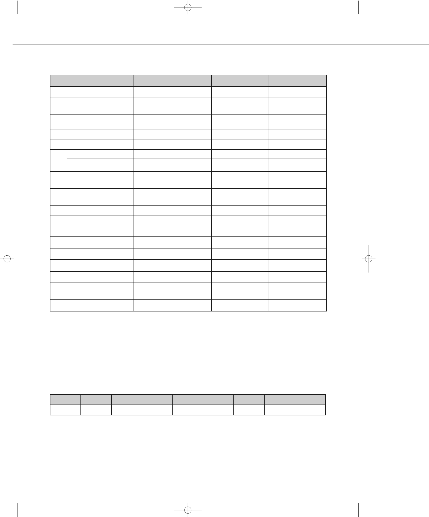
Sent Commands
The following commands are sent from the MIX 10 NG2:
“10” ~ “15” represent the channels MIC1~MIC6.
“00” ~ “04” represent the channels LINE, SUB-L, SUB-R, MASTER-L,MASTER-R.
An acknowledged message is directly sent from the MIX 10 NG2 after having received a request.
Example:
Selection of the CD line input
DLE STX Device No. Len Cmd Data DLE ETX Check Sum
10 02 01 02 A1 03 10 03 A0
Cmd Data0 Data1 Command Data0 Data1
C1 00~04 Line source selected line 1 - 4 or none(0)
C2 00~4F 00~04 Stereo volume currently adjusted
value “N”
N - value stereo no
C3 00~4F 10~15 Mic volume currently adjusted value
“N”
N - value mic no
C4 00~4F 00~04 Stereo volume now value “N” N - value stereo no
C5 00~4F 10~15 Mic volume now value “N” N - value mic no
C8 20Bit 0 Auto ducking 1 = on , 0 = off
21Bit 1 Ducking manually 1 = on , 0 = off
C9 00~01 10~15 Mic ducking 01 = enabled ,
00= disabled mic no
CA 00~01 01~02 Stereo ganged 01 = enabled ,
00= disabled
01 = sub group,
02 = master
CB 00~03 00~01 Load or save preset 0-default / preset 1,2,3 00 = load , 01 = save
CE 00~01 00~04,10~15 Mute flag 1 = on , 0 = off stereo / mic
D0 00~7F Fade-out speed N - value
D1 00~7F Fade-in speed N - value
D2 00~7F Ducking threshold value N - value
D3 00~4F Ducking reduction N - value
D4 00~7F Ducking hold N - value
D7 00~03 Switch-on status preset 1/2/3/switch-off
status(0)
D8 Programmed version (V 1.0)
PC –> Device
MIX10NG2_BA_DE_2008:MIX10NG_BA_DE 01.02.2008 10:30 Uhr Seite 30
MIX 10 NG2 – RS 232 Interface 31
english
Check Sum
The check sum results from a vertical XOR comparison of the individual command bytes in the binary system. The check sum for the example
on the previous page results in:
Subject to change without notice.
Hex number Binary number
10 0001 0000
02 0000 0010
01 0000 0001
02 0000 0010
A1 1010 0001
03 0000 0011
10 0001 0000
03 0000 0011
A0 1010 0000
MIX10NG2_BA_DE_2008:MIX10NG_BA_DE 01.02.2008 10:30 Uhr Seite 31

MIX 10 NG2 – Technical Specifications 32
8. Technical Specifications
Frequency response. . . . . . . . . . . . . . . . . . . . 22 - 22,000 Hz (-3 dB)
Gain . . . . . . . . . . . . . . . . . . . . . . . . . . . . . . . 0 dB - 56 dB
Distortion (THD) . . . . . . . . . . . . . . . . . . . . . . 0.3% @ 1 kHz, 6 dBu Output, max. gain
Signal-to-noise ratio . . . . . . . . . . . . . . . . . . . 93 dB @ 1 kHz, 15 dBu Output, 1% THD+N, max. gain
Microphone inputs
Characteristics. . . . . . . . . . . . . . . . . . . . . . . . electronically balanced
Input impedance . . . . . . . . . . . . . . . . . . . . . . 600 Ω
Input level . . . . . . . . . . . . . . . . . . . . . . . . . . . max. 4 dBu @ 0.5% THD+N, min. gain
Phantom power . . . . . . . . . . . . . . . . . . . . . . 27 V, switchable
Connection . . . . . . . . . . . . . . . . . . . . . . . . . . removable terminals per input
Priority control . . . . . . . . . . . . . . . . . . . . . . . Ducking function on Mic 1 or all mic inputs, -40 dB, can be switched off internally
Stereo line inputs
Characteristics. . . . . . . . . . . . . . . . . . . . . . . . unbalanced
Input impedance . . . . . . . . . . . . . . . . . . . . . . 7 kΩ
Connection . . . . . . . . . . . . . . . . . . . . . . . . . . 2 x RCA (phono) per input
Stereo mix input
Characteristics. . . . . . . . . . . . . . . . . . . . . . . . unbalanced
Input impedance . . . . . . . . . . . . . . . . . . . . . . 20 kΩ
Connection . . . . . . . . . . . . . . . . . . . . . . . . . . 2 x RCA (phono)
Equalisation
Bass . . . . . . . . . . . . . . . . . . . . . . . . . . . . . . . 40 Hz, ±12 dB
Treble . . . . . . . . . . . . . . . . . . . . . . . . . . . . . . 13.5 kHz, ±12 dB
Main outputs stereo
Characteristics. . . . . . . . . . . . . . . . . . . . . . . . electronically balanced
Output impedance . . . . . . . . . . . . . . . . . . . . 50 Ω
Output level . . . . . . . . . . . . . . . . . . . . . . . . . 6.9 Veff (+19 dBu)
Connection . . . . . . . . . . . . . . . . . . . . . . . . . . 2 x 3-pin terminals
Characteristics. . . . . . . . . . . . . . . . . . . . . . . . unbalanced
Output impedance . . . . . . . . . . . . . . . . . . . . 50 Ω
Output level . . . . . . . . . . . . . . . . . . . . . . . . . 3.45 Veff (+13 dBu)
Connection . . . . . . . . . . . . . . . . . . . . . . . . . . 2 x RCA (phono)
Sub output
Characteristics. . . . . . . . . . . . . . . . . . . . . . . . electronically balanced
Output impedance . . . . . . . . . . . . . . . . . . . . 50 Ω
Output level . . . . . . . . . . . . . . . . . . . . . . . . . 6.9 Veff (+19 dBu)
Connection . . . . . . . . . . . . . . . . . . . . . . . . . . 2 x 3-pin terminals
Record output (microphone master mono)
Characteristics. . . . . . . . . . . . . . . . . . . . . . . . unbalanced
Output impedance . . . . . . . . . . . . . . . . . . . . 50 Ω
Output level . . . . . . . . . . . . . . . . . . . . . . . . . 3.45 Veff (+13 dBu)
Connection . . . . . . . . . . . . . . . . . . . . . . . . . . 2 x RCA (phono)
PC connection. . . . . . . . . . . . . . . . . . . . . . . . RS 232
Mains voltage . . . . . . . . . . . . . . . . . . . . . . . . 230 V AC
Dimensions . . . . . . . . . . . . . . . . . . . . . . . . . . 19"/1 U Rack Unit (1.75") (H x W x D / 44 x 483 x 135 mm)
Weight . . . . . . . . . . . . . . . . . . . . . . . . . . . . . 2.9 kg
MIX10NG2_BA_DE_2008:MIX10NG_BA_DE 01.02.2008 10:30 Uhr Seite 32
MIX 10 NG2 – Block Diagram 33
english
9. Block Diagram
MIX10NG2_BA_DE_2008:MIX10NG_BA_DE 01.02.2008 10:30 Uhr Seite 33

EC-DECLARATION
OF CONFORMITY
Application of
Council Directive: 89/336/EEC, 93/68/EEC
Electromagnetic Compatibility
73/23/EEC, 93/68/EEC
Low Voltage Directive
Standards to which
Conformity is declared: EN 55 022 Emission
IEC 61 000 - 4 - 2 ESD
IEC 61 000 - 4 - 3 Radiated field
IEC 61 000 - 4 - 6 Conducted immunity
IEC/EN/UL 60 065 Product Safety
Manufacturer’s Name: beyerdynamic GmbH & Co. KG
Manufacturer’s Address: Theresienstrasse 8, 74072 Heilbronn, Germany
Type of Equipment: Mixing Amplifier
Model Numbers: MIX 10 NG2
I, the undersigned, as an employee of beyerdynamic, hereby declare that the equipment specified conforms to the above Directive and
Standards.
Manufacturer’s Signature:
Date: 1 February 2008
Full Name: Ulrich Roth
Position: Director of R&D
MIX10NG2_BA_DE_2008:MIX10NG_BA_DE 01.02.2008 10:30 Uhr Seite 34

MIX10NG2_BA_DE_2008:MIX10NG_BA_DE 01.02.2008 10:30 Uhr Seite 35

DE 1/BA MIX 10 NG2 (01.08)/ Änderungen und Irrtümer vorbehalten • Subject to change without notice
beyerdynamic GmbH & Co. KG
Theresienstr. 8
74072 Heilbronn, Germany
Tel. +49 (0 ) 71 31 6 17-0
Fax +49 (0 ) 71 31 617-224
E-mail: info@beyerdynamic.de
Internet: www.beyerdynamic.de
beyerdynamic Inc. USA
56 Central Ave.
Farmingdale, NY 11735
Tel. +1 (631) 293-3200
Fax +1 (631) 293-3288
E-mail: salesUSA@beyerdynamic.com
Internet: www.beyerdynamic.com
beyerdynamic U.K. Ltd.
17 Albert Drive
Burgess Hill RH15 9TN
Tel. +44 (0) 1444 258 258
Fax +44 (0) 1444 258 444
E-mail: sales@beyerdynamic.co.uk
Internet: www.beyerdynamic.co.uk
MIX10NG2_BA_DE_2008:MIX10NG_BA_DE 01.02.2008 10:30 Uhr Seite 36