Beyerdynamic QUINTATB Microphone Unit User Manual Layout 1
Beyerdynamic Microphone Unit Layout 1
Contents
- 1. user manual part 2
- 2. user manual part 1
user manual part 2

QUINTA
DIGITALES DRAHTLOSES KONFERENZSYSTEM
DIGITAL WIRELESS CONFERENCE SYSTEM
SYSTÈME NUMÉRIQUE SANS FIL DE CONFERENCE
Guide de démarrage rapide
Quick Start Guide
Kurzanleitung
Registrierung
Bitte registrieren Sie sich unter www.beyerdynamic.com/quinta/register. Wir werden Sie über Soft-
ware-Updates und Neuheiten rund um unsere Quinta-Produktfamilie informieren. Bei Registrierung
können Sie das Bedienmodul der Konferenzsoftware (Quinta Conference Controller) gratis dazu er-
halten.
Registration
Please register at www.beyerdynamic.com/quinta/register. We will inform you about software updates
and new developments of our Quinta product range. When registering you will be eligible to receive
the Conference software control module (Quinta Conference Controller) free of charge.
Enregistrement
Veuillez vous enregistrer sur www.beyerdynamic.com/quinta/register. Nous vous ferons parvenir des
informations sur les mises à jour logicielles et nouveautés tout autour de notre gamme de produits
Quinta. En vous enregistrant, vous pouvez recevoir gratuitement le module de pilotage du logiciel de
conférence (Quinta Conference Controller).

Quick Start Guide Quinta – Inhalt / Contents / Sommaire 3
Quick Start Guide Quinta
deutsch
1. Einführung. . . . . . . . . . . . . . . . . . . . . . . . . . . . Seite 4
2. Bedien- und Kontrollelemente . . . . . . . . . . . . . . Seite 4
2.1 Steuerzentrale Quinta CU . . . . . . . . . . . . . . Seite 4
2.2 Sprechstellen Quinta MU . . . . . . . . . . . . . . Seite 5
2.3 Grenzflächenmikrofon Quinta TB. . . . . . . . . Seite 8
3. Inbetriebnahme . . . . . . . . . . . . . . . . . . . . . . . . Seite 9
3.1 Steuerzentrale Quinta CU . . . . . . . . . . . . . . Seite 9
3.2 Sprechstellen Quinta MU . . . . . . . . . . . . . Seite 10
3.3 Grenzflächenmikrofon Quinta TB . . . . . . . . Seite 12
4. Entsorgung . . . . . . . . . . . . . . . . . . . . . . . . . . . Seite 13
5. Konformitätserklärung. . . . . . . . . . . . . . . . . . . . Seite 13
Quick Start Guide Quinta
Quick Start Guide Quinta
englishfrançais
1. Introduction . . . . . . . . . . . . . . . . . . . . . . . . . . . Page 14
2. Controls and Indicators . . . . . . . . . . . . . . . . . . . Page 14
2.1 Quinta CU Control Unit . . . . . . . . . . . . . . . Page 14
2.2 Quinta MU Microphone Units . . . . . . . . . . . Page 15
2.3 Quinta TB Boundary Microphone. . . . . . . . . Page 18
3. How to Operate the System . . . . . . . . . . . . . . . . Page 19
3.1 Quinta CU Control Unit . . . . . . . . . . . . . . . Page 19
3.2 Quinta MU Microphone Units . . . . . . . . . . . Page 20
3.3 Quinta TB Boundary Microphone. . . . . . . . . Page 22
4. Disposal. . . . . . . . . . . . . . . . . . . . . . . . . . . . . . Page 23
5. EU Declaration of Conformity. . . . . . . . . . . . . . . Page 23
FCC Regulation . . . . . . . . . . . . . . . . . . . . . . . . . . . Page 24
1. Introduction . . . . . . . . . . . . . . . . . . . . . . . . . . . Page 26
2. Eléments de commande et de contrôle . . . . . . . . Page 26
2.1 Centrale de commande Quinta CU. . . . . . . . Page 26
2.2 Postes d’appel Quinta MU . . . . . . . . . . . . . Page 27
2.3 Microphone à effet de surface Quinta TB . . Page 30
3. Mise en service . . . . . . . . . . . . . . . . . . . . . . . . Page 31
3.1 Centrale de commande Quinta CU. . . . . . . . Page 31
3.2 Postes d’appel Quinta MU . . . . . . . . . . . . . Page 32
3.3 Microphone à effet de surface Quinta TB . . Page 34
4. Evacuation. . . . . . . . . . . . . . . . . . . . . . . . . . . . Page 35
5. Déclaration de conformité . . . . . . . . . . . . . . . . . Page 35
FCC Régulation . . . . . . . . . . . . . . . . . . . . . . . . . . . Page 36

1. Einführung
Sie haben sich für das drahtlose digitale Konferenzsystem Quinta von beyerdynamic entschieden. Wir
danken für Ihr Vertrauen. Nehmen Sie sich bitte einige Minuten Zeit und lesen Sie diese Information
vor Inbetriebnahme aufmerksam durch.
Eine ausführliche Beschreibung des Quinta-Systems und der Quinta Conference Software finden Sie in den
jeweiligen Bedienungsanleitung „Quinta Konferenzsystem“ bzw. „Quinta Conference Software“ im
Internet unter: www. beyerdynamic.de
Bitte beachten Sie unbedingt das beigelegte Heft „Sicherheitshinweise“.
2. Bedien- und Kontrollelemente
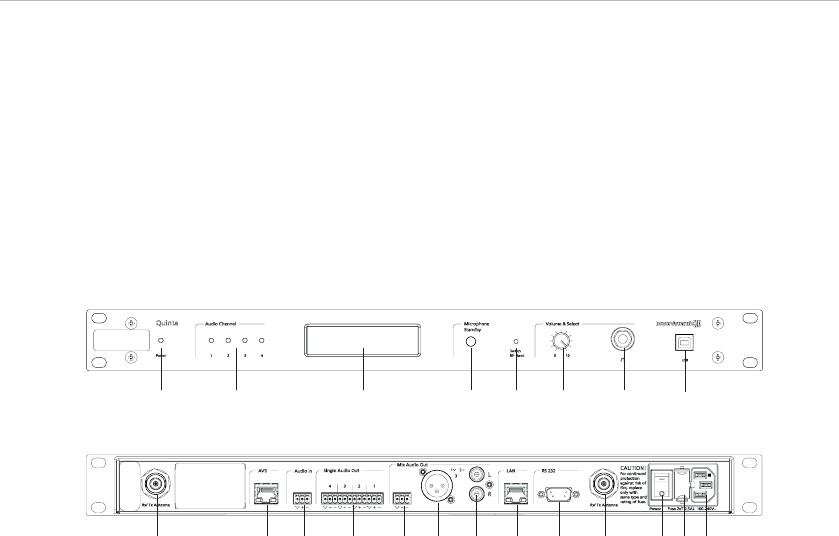
2.1 Steuerzentrale Quinta CU
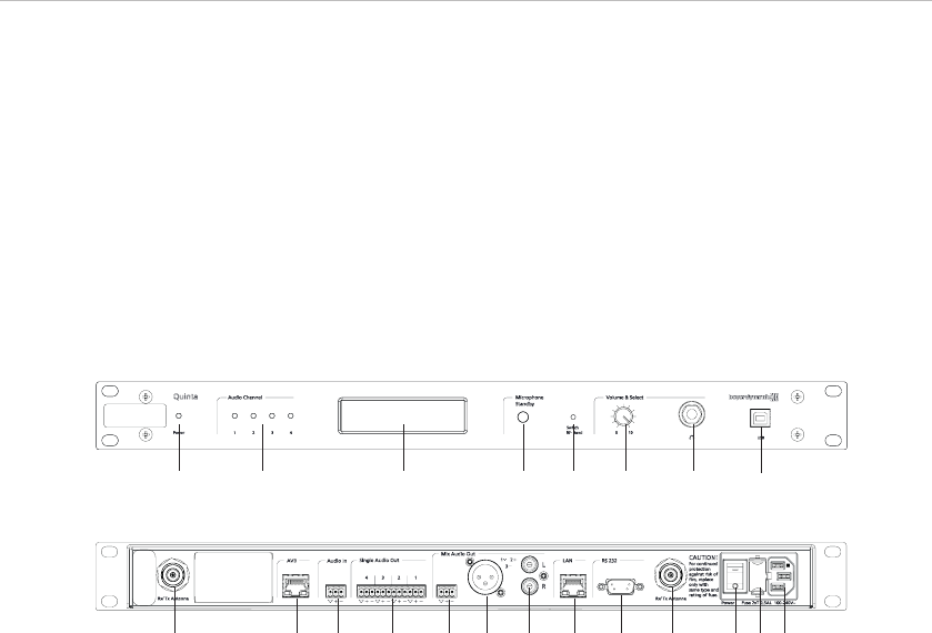
ᕡBetriebsanzeige
ᕢAudiokanalanzeige 1 bis 4 (weiß = Kanal verfügbar; rot = Kanal belegt)
ᕣDisplay zur Anzeige von Betriebsart, Kanal, Kopfhörerlautstärke
ᕤStandby-Taster zum zentralen Ausschalten aller Sprechstellen
ᕥVersenkter Taster für Frequenzumschaltung
ᕦLautstärkeregler für Kopfhörer / Kanal
ᕧKopfhöreranschluss
ᕨUSB-Anschluss
ᕩAntennenanschlüsse
µAVB (Audio-Video-Bridging) Netzwerkanschluss für digitale Audiosignale über CAT5-Kabel, RJ 45
¸Audioeingang (Audio IN) zum Einschleifen externer Signalquellen, 3-pol. Phönix-Klemmleiste,
symmetrisch
¹Audioausgang, Einzelkanäle, 4 x 3-pol. Phönix-Klemmleiste, symmetrisch
ƸAudioausgang Mix (Summe), 3-pol. Phönixklemmleiste, symmetrisch
ƹAudioausgang Mix (Summe), 3-pol. XLR, symmetrisch
ƺAudioausgang Mix (Summe), Cinch, unsymmetrisch
ƻLAN-Anschluss für PC / Netzwerk, RJ 45
ƼAnschluss für Mediensteuerung / PC / Netzwerk, RS 232
ƽNetzschalter
ƾSicherung
ƿNetzanschluss
Quick Start Guide Quinta – Steuerzentrale Quinta CU
4
Vorderseite
Rückseite
ᕡ
ᕩ µ ¸ ¹ Ƹ ƹ ƺ ƻ Ƽ ᕩ ƽ ƾ ƿ
ᕢ ᕣ ᕤ ᕥ ᕦ ᕧ ᕨ
Quick Start Guide Quinta – Sprechstellen Quinta MU 5
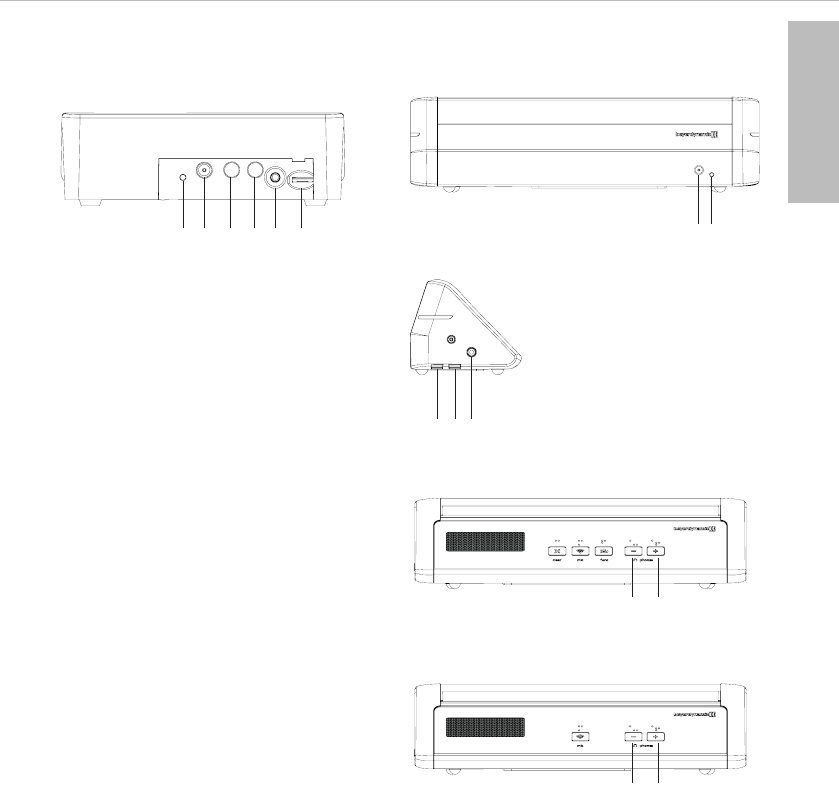
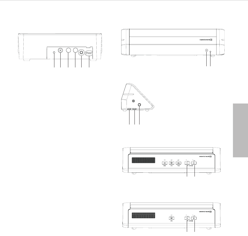
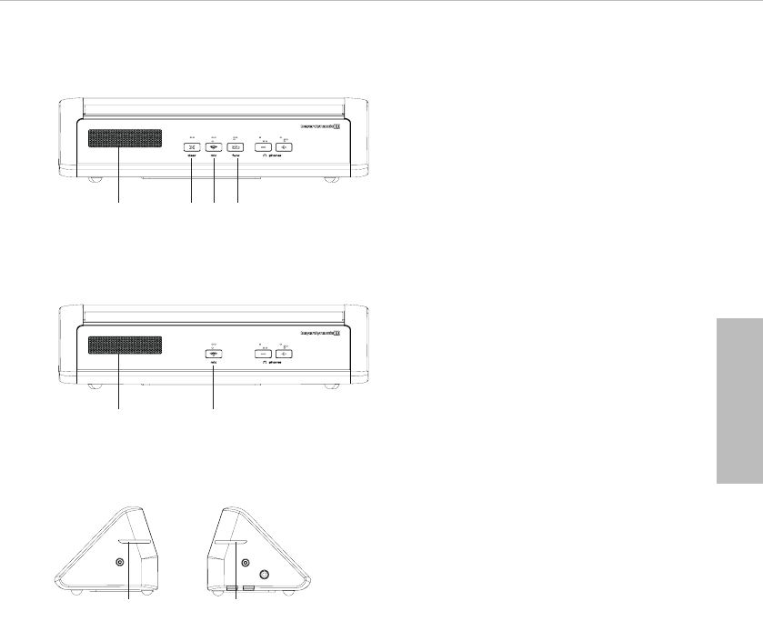
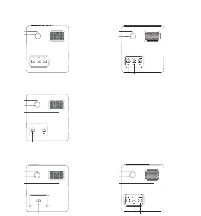
2.2 Sprechstellen Quinta MU 23/22/21/MU 23 V/MU 21 V und Quinta MU 33/31
ቢBetriebs- und Kontrollanzeige
ባDC-Anschluss zum Laden des Sprechstellenakkus oder für DC-Betrieb
ቤLadekontakte zum Laden in der Ladeetage CD 2 (für Quinta MU 23/22/21/MU 23 V/MU 21 V)
bzw. CD 3 (für Quinta MU 33/31)
ብKopfhöreranschluss
ቦLautstärkeregler für Kopfhöreranschluss
deutsch
ቢ
ባ ቤ
ቤ
ብ ቦ
Quinta MU 23/22/21/MU 23 V/MU 21 V – Rückseite Quinta MU 33/31 – Rückseite
Quinta MU 33/31 – Seitenansicht
Quinta MU 33 – Vorderseite
ቢ
ባ
ቤ ቤ
ብ
ቦ ቦ
Quinta MU 31 – Vorderseite
ቦ ቦ

Quick Start Guide Quinta – Sprechstellen Quinta MU
6
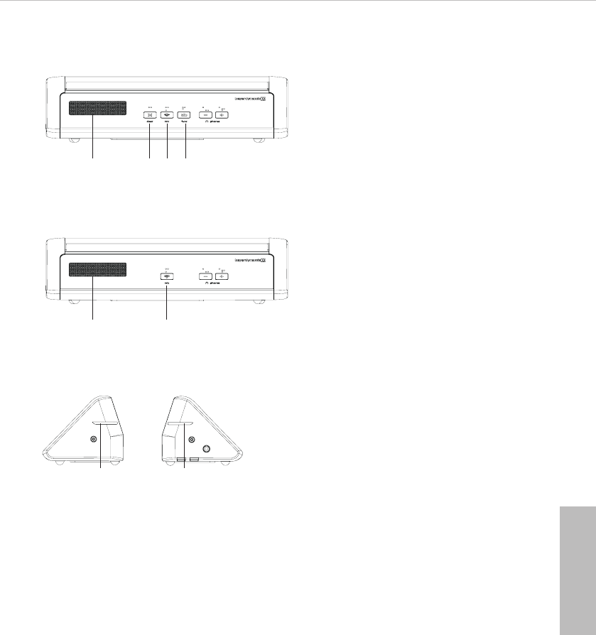
Sprechstellen Quinta MU 23/22/21 und Quinta MU 23 V/MU21 V
ቧ
ቨ
ቩ
ቫቭቪ
Präsidentensprechstelle Quinta MU 23
ቧ
ቨ
ቩ
ቫቭቪ
Präsidentensprechstelle Quinta MU 23 V
Doppeldelegiertensprechstelle Quinta MU 22
Delegiertensprechstelle Quinta MU 21
ቧ
ቨ
ቩ
ቫቫ
ቧ
ቨ
ቩ
ቫ
Delegiertensprechstelle Quinta MU 21 V
ቧ
ቨ
ቩ
ቫቯ ተ

Quick Start Guide Quinta – Sprechstellen Quinta MU 7
ቧEntriegelungsöffnung für Schwanenhalsmikrofon
ቨAnschluss für Schwanenhalsmikrofon
ቩLautsprecher
ቪ„Clear“-Taste zum Löschen der Delegiertensprechstellen / Achtung: Nur bei Quinta MU 23 V fungiert
dieselbe Taste auch als Abstimmtaste „yes“ („Ja“)
ቫMikrofontaste / Achtung: Nur bei Quinta MU 23 V / MU 21 V fungiert dieselbe Taste auch als
Abstimmtaste „no“ („Nein“)
ቭProgrammierbare Funktionstaste / Achtung: Nur bei Quinta MU 23 V fungiert dieselbe Taste
auch als Abstimmtaste „abstain“ („Enthaltung“)
ቮLED-Streifen
ቯAbstimmtaste „Yes“ bei Quinta MU 21 V
ተAbstimmtaste „Abstain“ bei Quinta MU 21 V
Präsidentensprechstelle Quinta MU 33
ቪ ቫ ቭቩ
Delegiertensprechstelle Quinta MU 31
ቫ
ቩ
Seitenansicht Quinta MU 33/31
ቮቮ
Sprechstellen Quinta MU 33/31
deutsch

Quick Start Guide Quinta – Grenzflächenmikrofon Quinta TB
8
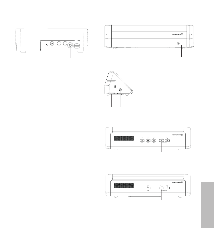
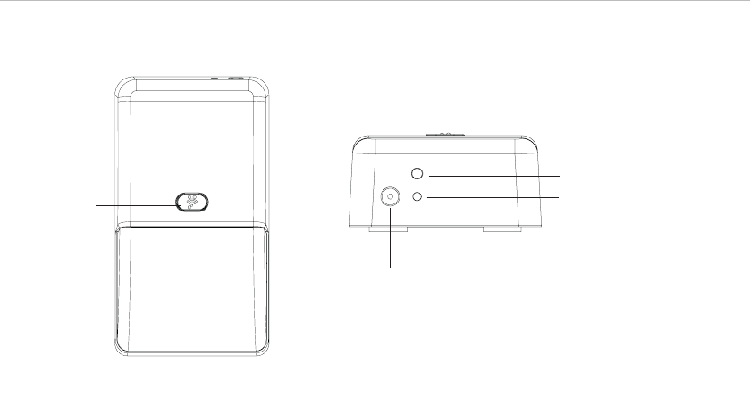
2.3 Grenzflächenmikrofon Quinta TB
ቢMikrofontaste
ባDC-Anschluss für Laden oder Netzbetrieb
ቤTaster zum Ausschalten des kompletten Gerätes
ብBetriebskontroll-LED
ቢ
ቤ
ባ
ብ

Quick Start Guide Quinta – Inbetriebnahme 9
3. Inbetriebnahme
3.1 Steuerzentrale Quinta CU
Aufstellen der Steuerzentrale
• Wenn Sie keine abgesetzten Antennen verwenden, stellen Sie die Steuerzentrale Quinta CU in dem
Raum auf, in dem die Konferenz stattfindet. Bei abgesetzten Antennen, stellen Sie die Antennen in
dem Raum auf, in dem die Konferenz stattfindet.
• Vermeiden Sie Abschattungen der Antennen, insbesondere durch metallische Flächen.
• Die Sprechstellen Quinta MU arbeiten optimal bei direkter Sichtverbindung zu den Antennen der
Steuerzentrale Quinta CU.
Antennenanschluss
• Schließen Sie die Antennen an die Antennenanschlüsse ᕩ an. Für den Diversitybetrieb müssen
unbedingt beide Antennen angeschlossen sein! Eine Auswerteelektronik schaltet sowohl in
Empfangs- als auch in Senderichtung geräuschlos auf die Antenne mit dem jeweils besseren
Antennensignal.
• Für den Stand-Alone-Betrieb empfehlen wir die mitgelieferten Stabwinkelantennen CA Q 11.
• Die Steuerzentrale Quinta CU kann auch mit abgesetzten Antennen betrieben werden. Als
empfohlene Anschlusskabel dienen extrem dämpfungsarme Kabel in den Längen 10 m und 20 m.
Beachten Sie, dass die Antennen abgesetzt montiert werden müssen.
Anschlüsse
• Verbinden Sie bei Bedarf den Summenausgang Audio Mix Ƹ, XLR ƹoder Cinch ƺder Steuer-
zentrale Quinta CU mit dem Eingang eines Mischverstärkers oder Mischpultes.
• Schließen Sie die Steuerzentrale Quinta CU ans Netz ƿan. Das Netzteil der Steuerzentrale kann
sich automatisch auf eine Wechselspannung zwischen 100 und 240 Volt bei 50 - 60 Hz einstellen.
Überprüfen Sie, ob die Anschlusswerte mit der vorhandenen Netzstromversorgung übereinstimmen.
Bei Anschluss des Systems an die falsche Stromversorgung können ernsthafte Schäden
entstehen.Achten Sie darauf, dass das Netzkabel nicht geknickt oder durchtrennt werden kann.
• Zur Verwendung des AVB-Anschlusses siehe die Bedienungsanleitung „Quinta Konferenzsystem“.
Bedienhinweise
• Schalten Sie die Steuerzentrale Quinta CU mit dem Ein-/Ausschalter ƽein. Die Betriebsanzeige ᕡ
leuchtet.
• Die Kanalanzeigen 1 bis 4 leuchten weiß und zeigen so ihre Verfügbarkeit an. Sobald ein Mikrofon
offen ist, leuchtet die Kanalanzeige ᕢrot und zeigt so an, dass der Kanal belegt ist.
• Werkseitig sind die HF-Bänder 2,4; 5,2 oder 5,8 GHz* aktiviert (Automatic Mode). Das bedeutet,
die Steuerzentrale Quinta CU wählt selbständig eine freie Frequenz aus und springt bei
Bedarf ohne Audiostörungen dynamisch auf eine andere freie Frequenz. Diese Betriebsart wird für
den normalen Gebrauch empfohlen. Die für die Steuerzentrale Quinta CU frei verfügbaren
Frequenzen können per Software zusätzlich deaktiviert werden. Die Sprechstellen werden
automatisch ohne Audiounterbrechung auf die Frequenz der Steuerzentrale Quinta CU eingestellt.
Siehe hierzu auch die Bedienungsanleitung „Quinta Konferenzsystem“.
*Hinweis:
Die Verfügbarkeit der HF-Bänder 2,4; 5,2 oder 5,8 GHz kann je nach gewählter Region abweichen.
deutsch

Quick Start Guide Quinta – Inbetriebnahme
10
3.2 Sprechstellen Quinta MU 23/22/21/MU 23 V/MU 21 V und Quinta MU 33/31
Schwanenhalsmikrofon an Quinta MU 23/22/21/MU 23 V/MU 21 V anschließen
Für den Anschluss an die Sprechstellen Quinta MU 23/22/21/MU 23 V/MU 21 V stehen Schwanen-
halsmikrofone mit LED zur Verfügung.
• Fassen Sie das Schwanenhalsmikrofon unten am Schaft, setzen Sie es entsprechend in die Buchse ቨ
ein und drücken Sie es am Schaft nach unten bis es einrastet.
• Wollen Sie das Schwanenhalsmikrofon entnehmen, drücken Sie zum Entriegeln mit dem im
Lieferumfang der Quinta CU enthaltenen Entriegelungswerkzeug oder einem ähnlich dünnen Werk-
zeug auf die Entriegelungsöffnung ቧ und entnehmen das Schwanenhalsmikrofon, indem Sie es
unten am Schaft fassen und herausziehen.
Einschalten
• Durch Drücken der Mikrofontaste wird die Sprechstelle eingeschaltet. Dabei leuchtet die Mikrofon-
taste ቫkurz auf und die Betriebskontroll-LED ቢauf der Rückseite leuchtet grün.
Sobald eine Verbindung zur Steuerzentrale Quinta CU hergestellt wurde, leuchten die Tasten der
Sprechstelle zur Bereitschaftsanzeige weiß.
• Um das Mikrofon zu aktivieren bzw. die Sprechstelle einem freien Kanal der Steuerzentrale Quinta
CU zuzuteilen, drücken Sie noch einmal kurz auf die Mikrofontaste ቫ. Je nach Betriebsart leuchtet
die Mikrofontaste grün (Betriebsart normal) oder rot (Betriebsart Anmeldung).
Ausschalten
• Durch langes Drücken der Mikrofontaste ቫ (> 2 Sek.) wird die Sprechstelle ausgeschaltet.
• Alle eingeschalteten Sprechstellen Quinta MU in „Reichweite“ der Steuerzentrale Quinta CU
können auch über die Steuerzentrale ausgeschaltet werden, wenn Sie den Standby-Taster ᕤ länger
als 3 Sekunden drücken.
• Außerdem schalten sich die Sprechstellen selbsttätig aus, wenn sie länger als ca. 3 Minuten kein
Signal von der Steuerzentrale Quinta CU empfangen.
Betriebsarten
Die verschiedenen Betriebsarten wie „Normal“, „Push-To-Talk“ oder „Sprachaktiviert“ werden mit
der Quinta Conference Software für alle Sprechstellen gemeinsam eingestellt. Die ab Werk einge-
stellte Betriebsart ist „Normal“. Siehe hierzu die entsprechende Bedienungs anleitung „Quinta
Conference Software“ bzw. „Quinta Webserver“.
Speisung / Betriebszeit
• Die Sprechstellen haben einen integrierten Akku, der im vollgeladen Zustand eine Betriebszeit von
ca. 20 Stunden gewährleistet.
• Bei nachlassender Spannung blinkt die Betriebskontroll-LED ቢauf der Rückseite der Sprechstelle.
Die Restbetriebszeit beträgt ca. eine Stunde.
• Der Ladezustand der Sprechstellen kann mit der Quinta Conference Software auf einem an die
Steuerzentrale Quinta CU angeschlossenen PC oder über den integrierten Webserver angezeigt
werden. Außerdem ist die Anzeige auf einer an die Quinta CU angeschlossenen externen Medien-
steuerung möglich.
• Die Sprechstellen Quinta MU können auch über das externe Einzellade-Netzteil CA 2459 gespeist
werden, welches Sie an den DC-Anschluss ባauf der Rückseite der jeweiligen Sprechstelle
anschließen.
• Während das Einzellade-Netzteil CA 2459 angeschlossen ist, wird die Sprechstelle auch geladen.

Quick Start Guide Quinta – Inbetriebnahme 11
deutsch
Laden
Mit der im Transportkoffer Quinta CC 2 integrierten Ladeetage Quinta CD 2 können bis zu 10 Sprech-
stellen Quinta MU 23/22/21/MU 23 V/MU 21 V gleichzeitig geladen werden. Mit der im Transport-
koffer Quinta CC 3 integrierten Ladeetage Quinta CD 3 können bis zu 12 Sprechstellen Quinta
MU 33/31 gleichzeitig geladen werden. Der Ladezustand ist über das Sichtfenster von außen ein-
sehbar.
1. Schließen Sie die Ladeetage ans Netz an und schalten Sie sie mit dem Ein-/Ausschalter ein. Der
Schalter leuchtet.
Erst Netzstecker ziehen – dann Ladekoffer bewegen.
Um Schäden an der Netzbuchse sowie einen dadurch möglichen elektrischen Schlag zu ver-
meiden, darf der Ladekoffer nicht bewegt werden, wenn er an einer Netzsteckdose ange-
schlossen ist.
2. Schieben Sie die ausgeschalteten Sprechstellen in die Ladefächer. Eventuell noch eingeschaltete
Sprechstellen werden automatisch ausgeschaltet. Werden die Sprechstellen wieder dem Ladefach
entnommen, müssen sie von Hand eingeschaltet werden.
3. Der Ladevorgang wird durch die LED am Schwanenhals (Quinta MU 23/22/21/MU 23 V/MU 21 V)
bzw. den LED-Streifen (Quinta MU 33/31) angezeigt und ist von außen durch ein Sichtfenster ein-
sehbar.
LED-Anzeige bei Ladevorgang des Akkus:
a) Schwanenhals-LED bzw. LED-Streifen blinkt bzw. blinken rot. . . . . Akku wird geladen
b) Schwanenhals-LED bzw. LED-Streifen leuchtet bzw.
leuchten dauerhaft rot . . . . . . . . . . . . . . . . . . . . . . . . . . . . . . . . Akku vollständig geladen
c) Schwanenhals-LED bzw. LED-Streifen blinkt bzw. blinken schnell rot Fehlermeldung
• Die Sprechstellen Quinta MU können auch über das externe Einzellade-Netzteil CA 2459 geladen
werden, welches Sie an die DC-Buchse ባanschließen.
• Der Ladevorgang wird durch die Betriebskontroll-LED ቢangezeigt.
LED-Anzeige bei Ladevorgang des Akkus:
a) LED blinkt rot . . . . . . . . . . . . . . . . . . . . . . . . . . . . . . . . . . . . . . Akku wird geladen
b) LED leuchtet dauerhaft rot . . . . . . . . . . . . . . . . . . . . . . . . . . . . . Akku vollständig geladen
c) LED blinkt schnell rot. . . . . . . . . . . . . . . . . . . . . . . . . . . . . . . . . Fehlermeldung
•Pflegehinweis
Die Ladekontakte an den Sprechstellen und im Ladegerät sollten Sie von Zeit zu Zeit mit einem
weichen mit Spiritus oder Alkohol befeuchteten fusselfreien Tuch reinigen.

Quick Start Guide Quinta – Inbetriebnahme
12
3.3 Grenzflächenmikrofon Quinta TB
Einschalten
• Durch Drücken der Mikrofontaste ቢ wird das Grenzflächenmikrofon eingeschaltet. Dabei leuchtet
die Mikrofontaste ቢkurz auf und die Betriebskontroll-LED ብauf der Rückseite leuchtet grün.
Sobald eine Verbindung zur Steuerzentrale Quinta CU hergestellt wurde, leuchtet die Mikrofon-
taste ቢ des Grenzflächenmikrofons im Konferenzmodus zur Bereitschaftsanzeige weiß und im
Mikrofonmodus grün.
• Um das Mikrofon im Konferenzmodus zu aktivieren bzw. einem freien Kanal der Steuerzentrale
Quinta CU zuzuteilen, drücken Sie noch einmal kurz auf die Mikrofontaste ቢ. Je nach Betriebsart
leuchtet die Mikrofontaste ቢ grün (Betriebsart normal) oder rot (Betriebsart Anmeldung). Im
Mikrofonmodus ist das Mikrofon des Quinta TB automatisch aktiviert (Mikrofontaste ቢ leuchtet
grün). Um das Mikrofon stumm zu schalten, drücken Sie noch einmal kurz auf die Mikrofontaste ቢ
(Mikrofontaste ቢ leuchtet rot).
Ausschalten
• Durch langes Drücken der Mikrofontaste ቢ (> 2 Sek.) wird das Grenzflächenmikrofon ausgeschaltet.
• Alle eingeschalteten Mikrofone Quinta TB in „Reichweite“ der Steuerzentrale Quinta CU
können auch über die Steuerzentrale ausgeschaltet werden, wenn Sie den Standby-Taster ᕤ länger
als 3 Sekunden drücken.
• Außerdem schaltet sich das Grenzflächenmikrofon Quinta TB selbsttätig aus, wenn es länger als ca.
3 Minuten kein Signal von der Steuerzentrale Quinta CU empfängt.
Betriebsarten
Die verschiedenen Betriebsarten wie „Normal“, „Push-To-Talk“ oder „Push-To-Mute“ (nur im Mikro-
fonmodus verfügbar)“ werden mit der Quinta Conference Software für alle Mikrofone gemeinsam ein-
gestellt. Die ab Werk eingestellte Betriebsart ist „Normal“. Siehe hierzu die entsprechende
Bedienungs anleitung „Quinta Conference Software“ bzw. „Quinta Webserver“.
Speisung / Betriebszeit
• Die Grenzflächenmikrofone haben einen integrierten Akku, der im vollgeladenen Zustand eine
Betriebszeit von mindestens 16 Stunden gewährleistet.
• Bei nachlassender Spannung blinkt die Betriebskontroll-LED ብauf der Rückseite des Mikrofons.
Die Restbetriebszeit beträgt ca. eine Stunde.
• Der Ladezustand des Grenzflächenmikrofons kann mit der Quinta Conference Software auf einem
an die Steuerzentrale Quinta CU angeschlossenen PC oder über den integrierten Webserver
angezeigt werden. Außerdem ist die Anzeige auf einer an die Quinta CU angeschlossenen externen
Mediensteuerung möglich.
• Das Grenzflächenmikrofon Quinta TB kann auch über das externe Einzellade-Netzteil CA 2459
gespeist werden, welches Sie an den DC-Anschluss ባauf der Rückseite des jeweiligen Mikrofons
anschließen. Während das Einzellade-Netzteil CA 2459 angeschlossen ist, wird das Grenzflächen-
mikrofon auch geladen.
Laden
•Vor der ersten Inbetriebnahme müssen Sie den Akkupack im Grenzflächenmikrofon Quinta TB
aufladen. Die Ladedauer beträgt maximal 2 Stunden.
• Zum Laden schließen Sie das Ladenetzteil CA 2459 am Mikrofon sowie an einer Netzsteckdose an.
Ist das Mikrofon vor dem Laden eingeschaltet, leuchtet die Betriebskontroll-LED ብeinmal kurz rot
auf und dann als Betriebsanzeige permanent grün.
Quick Start Guide Quinta – Inbetriebnahme 13
4. Entsorgung
Dieses Produkt darf am Ende seiner Lebensdauer nicht über den normalen Haushaltsab-
fall entsorgt werden, sondern muss an einem Sammelpunkt für das Recycling von elektri-
schen und elektronischen Geräten abgegeben werden. Das Symbol auf dem Produkt, der
Gebrauchsanweisung oder der Verpackung weist darauf hin.
5. Konformitätserklärung
Hiermit erklärt beyerdynamic GmbH & Co. KG, dass das Funksystem Quinta mit der EU-Richtlinie
2014/53/EU konform ist.
Den vollständigen Text der EU-Konformitätserklärung finden Sie im Internet unter:
www.beyerdynamic.com/cod
deutsch
• Der Ladevorgang im ausgeschalteten Zustand des Mikrofons wird über die Betriebskontroll-LED ብ
wie folgt angezeigt:
a) LED blinkt langsam rot . . . . . . . . . . . . . . Akku wird geladen, normaler Ladevorgang
b) LED leuchtet dauerhaft rot. . . . . . . . . . . . Akku vollständig geladen
c) LED blinkt schnell rot . . . . . . . . . . . . . . . Fehlermeldung (in diesem Fall das Ladegerät
nochmals ausstecken und wieder anschließen,
ggf. Service rufen.)
Wichtig:
• Nach einiger Zeit verlieren Akkus technisch bedingt an Kapazität. Dadurch verkürzt sich die
Betriebszeit.
• Es ist normal, dass sich Akkus während des Ladevorgangs erwärmen.
• Wird das Grenzflächenmikrofon während des Ladevorgangs eingeschaltet, leuchtet die LED ብ grün.
Quick Start Guide Quinta – Quinta CU Control Unit
14
1. Introduction
Thank you for selecting the digital wireless Quinta conference system. Please take some time to read
carefully through this manual before setting up the equipment.
Please refer also to the extensive “Quinta Conference System” manual and “Quinta Conference
Software” manual which you will find in the internet at www.beyerdynamic.com.
Please also refer to the supplied “Safety Information” booklet.
2. Controls and Indicators
2.1 Quinta CU Control Unit
ᕡPower on LED
ᕢAudio channel LEDs 1 to 4 (white = channel vacant; red = channel occupied)
ᕣDisplay to indicate operating mode, channel, headphone volume
ᕤStandby button to turn off all microphone units centrally
ᕥPush-button for frequency band selection
ᕦVolume control for headphone / channel
ᕧHeadphone connection
ᕨUSB connection
ᕩAntenna connections
µAVB (Audio Video Bridging) network connection for digital audio signals via CAT5 cables, RJ45
¸Audio input (Audio IN) for the connection of external sound sources, 3-pin Phoenix terminal strip,
balanced
¹Audio output, individual channels, 4 x 3-pin Phoenix terminal strips, balanced
ƸAudio output Mix (Master), 3-pin Phoenix terminal strips, balanced
ƹAudio output Mix (Master), 3-pin XLR, balanced
ƺAudio output Mix (Master), RCA, unbalanced
ƻLAN connection for PC / network, RJ 45
ƼConnection for media control system / PC / network, RS 232
ƽOn/Off switch
ƾFuse
ƿMains connection
Front View
Rear View
ᕡ ᕢ ᕣ ᕤ ᕥ ᕦ ᕧ ᕨ
ᕩ µ ¸ ¹ Ƹ ƹ ƺ ƻ Ƽ ᕩ ƽ ƾ ƿ
Quick Start Guide Quinta – Quinta MU Microphone Units 15
english
2.2 Quinta MU 23/22/21/MU 23 V/MU 21 V and Quinta MU 33/31 Microphone Units
ቢPower on and operating control LED
ባDC socket for charging the rechargeable batteries of the microphone unit or for DC operation
ቤCharging contacts for charging in the CD 2 charger (Quinta MU 23/22/21/MU 23 V/MU 21 V)
or CD 3 (Quinta MU 33/31)
ብHeadphone connection
ቦVolume control for headphone connection
Quinta MU 23/22/21/MU 23 V/MU 21 V – Rear View Quinta MU 33/31 – Rear View
Quinta MU 33/31 – Front View
ቢ
ባ ቤ
ቤ
ብ ቦ
ቢ
ባ
ቤ ቤ
ብ
Quinta MU 33/31 – Lateral View
ቦ ቦ
Quinta MU 31 – Vorderseite
ቦ ቦ

Quick Start Guide Quinta – Quinta MU Microphone Units
16
Quinta MU 23/22/21 and Quinta MU 23 V/MU 21 V Microphone Units
ቧ
ቨ
ቩ
ቫቭቪ
Quinta MU 23 Chairman Microphone Unit
ቧ
ቨ
ቩ
ቫቭቪ
Quinta MU 23 V Chairman Microphone Unit
Quinta MU 22 Double Delegate Microphone Unit
Quinta MU 21 Delegate Microphone Unit
ቧ
ቨ
ቩ
ቫቫ
ቧ
ቨ
ቩ
ቫ
Quinta MU 21 V Delegate Microphone Unit
ቧ
ቨ
ቩ
ቫቯ ተ
Quick Start Guide Quinta – Quinta MU Microphone Units 17
english
Quinta MU 33/31 Microphone Units
ቧOpening for unlocking the gooseneck microphone
ቨConnection for gooseneck microphone
ቩLoudspeaker
ቪ“Clear” button to clear all delegate microphone units / Attention: Only with Quinta MU 23 V this
button acts also as “yes” voting button
ቫMicrophone button / Attention: Only with Quinta MU 23 V / MU 21 V this button acts also as “no”
voting button
ቭProgrammable function button / Attention: Only with Quinta MU 23 V this button acts also as
“abstain” voting button
ቮLED strips
ቯ“yes” voting button with Quinta MU 21 V
ተ“abstain” voting button with Quinta MU 21 V
Quinta MU 33 Chairman Microphone Unit
ቪ ቫ ቭቩ
Quinta MU 31 Delegate Microphone Unit
ቫ
ቩ
Quinta MU 33/31 Lateral View
ቮቮ

Quick Start Guide Quinta – Quinta TB Boundary Microphone
18
2.3 Quinta TB Boundary Microphone
ቢMicrophone button
ባDC socket for charging or for DC operation
ቤButton for turning off the complete device
ብPower on and operating control LED
ቢ
ቤ
ባ
ብ

Quick Start Guide Quinta – How to Operate the System 19
english
3. How to Operate the System
3.1 Quinta CU Control Unit
Where to place the control unit
• If you do not use remote antennae, place the Quinta CU control unit in the room where the
meeting takes place. If you use remote antennae, place the antennae in the conference room.
• Avoid shadowing effect of the antennae, especially by metallic surfaces.
• A free line of sight between the Quinta MU microphone units and the antennae of the Quinta CU
control unit is essential for the operation of the microphone units.
How to connect the antennae
• Connect the antennae to the antenna connections ᕩ. Please note that for diversity operation both
antennae have to be connected! A weighting circuit is used to make sure that the better antenna
signal is received.
• For stand-alone operation we recommend using the supplied CA Q 11 angled rod antennae.
• The Quinta CU control unit can also be operated with remote antennae. We recommed extremely
low attenuation connecting cables which are 10 m [32.8 ft] or 20 m [65.6 ft] long. Please note
that the antennae have to be installed remotely.
Connections
• If required, connect the Audio Mix Ƹ, XLR ƹor Cinch ƺmaster output of the Quinta CU control
unit to the input of a mixing console or amplifier.
• Connect the Quinta CU control unit to the mains ƿ. The internal power supply unit of the control
unit can automatically adjust between 100 and 240 V at 50 - 60 Hz. Verify that the voltage rating
of the unit matches that of the AC mains outlet you are to use. If you connect the unit to the wrong
voltage, you may seriously damage it. Always route cables running to the unit where they will not
be pinched or cut by heavy or sharp objects.
• For using the AVB network connection, please refer to the extensive “Quinta Conference System”
manual.
How to operate the control unit
• Turn on the Quinta CU control unit with the On/Off switch ƽ. The Power on LED ᕡwill illuminate.
• The channel LED 1 to 4 will illuminate white to indicate the availability. As soon as a microphone
is activated, the channel LED ᕢwill illuminate red to indicate that the channel is occupied.
• At the factory the RF bands 2.4; 5.2 or 5.8 GHz* will be activated (Automatic Mode). This means
that the Quinta CU control unit will select a free frequency and if necessary it will select a different
free frequency without any interferences. This operating mode is recommended for normal use.
The free frequencies for the Quinta CU control unit can be deactivated via the Quinta Conference
software. The microphone unit will automatically be adjusted and without any interruption to the
frequency of the Quinta CU control unit. Please refer also to the “Quinta Conference System”
manual.
*Note:
The availability of the RF bands 2.4; 5.2 or 5.8 GHz depends on the selected region.

Quick Start Guide Quinta – How to Operate the System
20
3.2 Quinta MU 23/22/21/MU 23 V/MU 21 V and Quinta MU 33/31 Microphone Units
How to connect the gooseneck microphone to Quinta MU 23/22/21/MU 23 V/MU 21 V
There are gooseneck microphones with an LED available to connect to the Quinta MU 23/22/21/
MU 23 V/MU 21 V microphone unit.
• Take the gooseneck microphone by the shaft, put it into the connection for gooseneck microphones ቨ
and press the shaft downwards until it locks in place.
• If you want to remove the gooseneck microphone, press into the opening for unlocking the goose-
neck microphone ቧwith the supplied tool or a similar thin tool. Remove the gooseneck micro-
phone by taking it by the shaft and pulling.
Switching on
• The microphone unit is switched on by pressing the microphone button. The microphone button ቫ
will light up for a moment and the operating control LED ቢ on the rear will illuminate green.
When the connection to the Quinta CU control unit has been established, the buttons of the
microphone unit will illuminate white.
• To activate the microphone or to allocate the microphone unit to a free channel of the Quinta CU
control unit, press the microphone button ቫ once again. Depending on the operating mode, the
microphone button will illuminate green (normal operating mode) or red (request-to-speak mode).
Switching off
• If you press the microphone button ቫ for more than 2 seconds the microphone unit will be
switched off.
• You can switch off all the active Quinta MU microphone units within the range of the Quinta CU
control unit when you press the standby button ᕤof the control unit for more than 3 seconds.
• Furthermore, the microphone units are switched off automatically, when they do not receive a
signal from the Quinta CU control unit for more than 3 minutes.
Operating modes
The different operating modes such as “Normal”, “Push-To-Talk” or “Voice Activation” are adjusted
with the Quinta Conference software for all microphone units. The standard operating mode is
“Normal”. Please refer also to the appropriate “Quinta Conference Software” or “Quinta Web Server”
manual.
Powering / operating time
• The microphone units have an integrated rechargeable battery allowing an operating time of
approx. 20 hours.
• As soon as the battery charge is too low for a satisfactory operation, the operating control LED ቢ
on the rear of the microphone unit will flash. The remaining time of operation is around 60 minutes.
• The charging state of the microphone units can be displayed with the Quinta Conference software
on a PC connected to the Quinta CU control unit or via the integrated web server. Furthermore, it
can be displayed on an external media control system connected to the Quinta CU control unit.
• The Quinta MU microphone units can be powered via the external CA 2459 mains charger adapter,
which is connected to the DC socket ባ on the rear of the microphone unit.
• While the CA 2459 mains charger adapter is connected, the rechargeable battery of the micro-
phone unit is charged.

Quick Start Guide Quinta – How to Operate the System 21
english
Charging
With the Quinta CD 2 charger integrated in the Quinta CC 2 transport case, it is possible to charge a
maximum of 10 Quinta MU 23/22/21/MU 23 V/MU 21 V microphone units. With the Quinta CD 3
charger integrated in the Quinta CC 3 transport case, it is possible to charge a maximum of 12 Quinta
MU 33/31 microphone units. The charging status can be seen from outside through a window.
1. Connect the charger to AC power and switch it on. The switch will illuminate.
Disconnect power plug first – then move charging case.
In order to avoid damages to the mains connection and a possible electrical shock caused
by this, you must not move the charging case when it is connected to an AC outlet.
2. Put the switched-off microphone units into the charging compartments. If microphone units are
switched on, they are switched off automatically. When the microphone units are used again, they
must be switched on.
3. The charging process is indicated by the LED of the gooseneck (Quinta MU 23/22/21/MU 23 V/
MU 21 V) or LED strips (Quinta MU 33/31) and can be seen from the outside through a glass
panel.
LED indicator when the rechargeable batteries are charged:
a) Gooseneck LED or LED strips are flashing red. . . . . . . . . . . . . . . . Battery is charged
b) Gooseneck LED or LED strips illuminate red permanently . . . . . . . Battery is completely full
c) Gooseneck LED or LED strips are flashing red rapidly . . . . . . . . . . Error
• The Quinta MU microphone units can also be charged with the external CA 2459 mains charger
adapter, which you can connect to the DC socket ባ.
• The charging process is indicated by the operating control LED ቢ.
LED indicator when the rechargeable batteries are charged:
a) Operating control LED is flashing red. . . . . . . . . . . . . . . . . . . . . . Battery is charged
b) Operating control LED illuminates red permanently. . . . . . . . . . . . Battery is completely full
c) Operating control LED is flashing red rapidly . . . . . . . . . . . . . . . . Error
•Maintenance note
From time to time clean the charging contacts of the microphone units and inside the charger with
a soft lint-free cloth moistened with spirits or alcohol.

Quick Start Guide Quinta – How to Operate the System
22
3.3 Quinta TB Boundary Microphone
Switching on
• The boundary microphone is switched on by pressing the microphone button ቢ. The microphone
button ቢ will light up for a moment and the operating control LED ብon the rear will illuminate
green.
When the connection to the Quinta CU control unit has been established, the microphone button ቢ
will illuminate white in the conference mode to display the ready for operation status and in the
microphone mode it will illuminate green.
• To activate the microphone in the conference mode or to allocate the microphone to a free channel
of the Quinta CU control unit, press the microphone button ቢbriefly once again. Depending on the
operating mode, the microphone button ቢ will illuminate green (normal operating mode) or red
(request-to-speak mode). In the microphone mode the microphone of the Quinta TB is automatically
activated (microphone button ቢ will illuminate green). In order to mute the microphone, press the
microphone button ቢ briefly once again (microphone button ቢ will illuminate red).
Switching off
• If you press the microphone button ቢ for more than 2 seconds, the boundary microphone will be
switched off.
• You can switch off all the active Quinta TB microphones within the range of the Quinta CU
control unit when you press the standby button ᕤof the control unit for more than 3 seconds.
• Furthermore, the Quinta TB boundary microphones are switched off automatically, when they do not
receive a signal from the Quinta CU control unit for more than 3 minutes.
Operating modes
The different operating modes such as “Normal”, “Push-To-Talk” or “Push-To-Mute” (available in the
microphone mode only) are adjusted with the Quinta Conference software for all microphones. The
standard operating mode is “Normal”. Please refer also to the appropriate “Quinta Conference
Software” or “Quinta Web Server” manual.
Powering / operating time
• The boundary microphones have an integrated rechargeable battery allowing an operating time of
approx. 16 hours.
• As soon as the battery charge is too low for a satisfactory operation, the operating control LED ብ
on the rear of the microphone will flash. The remaining time of operation is around 60 minutes.
• The charging state of the microphones can be displayed with the Quinta Conference software on a
PC connected to the Quinta CU control unit or via the integrated web server. Furthermore, it can
be displayed on an external media control system connected to the Quinta CU control unit.
• The Quinta TB boundary microphone can be powered via the external CA 2459 mains charger
adapter, which is connected to the DC socket ባon the rear of the microphone. While the CA 2459
mains charger adapter is connected, the rechargeable battery of the boundary microphone is charged.
Charging
•Before using the Quinta TB boundary microphone for the first time, you have to recharge the
integrated rechargeable batteries. The maximum charging time is approx. 2 hours.
• For charging connect the CA 2459 mains charger adapter to the microphone and to a power socket.
If the microphone is switched on when recharging, the operating control LED ብwill briefly
illuminate red for one time and then permanently green to indicate that the microphone is powered.
• When the microphone is switched off, the charging process is displayed by the operating control
LED ብas described in the following:
a) LED flashes slowly red . . . . . . . . . . . . . . Battery is charged, normal charging process
Quick Start Guide Quinta – How to Operate the System 23
english
b) LED illuminates permanently red . . . . . . . Battery is completely full
c) LED is flashing red rapidly . . . . . . . . . . . . Error (in this case disconnect the mains charger
adapter, then connect it again, if necessary call the
Service department)
Important:
• Depending on the kind and time of use as well as the number of charging cycles, rechargeable
batteries are subject to a natural aging process reducing the total capacity and the maximum operating
time.
• It is normal that rechargeable batteries are heated up during the charging process.
• If the boundary microphone is turned on while charging, the LED ብ will illuminate green.
4. Disposal
This symbol on the product, in the instructions or on the packaging means that your electrical
and electronic equipment should be disposed at the end of its life separately from your
household waste. There are separate collection systems for recycling in the EU. For more
information, please contact the local authority or your retailer where you purchased the
product.
5. EU Declaration of Conformity
Hereby beyerdynamic GmbH & Co. KG declares that the radio equipment type Quinta is in compliance
with Directive 2014/53/EU.
The full text of the EU declaration of conformity is available at the following internet address:
http://www.beyerdynamic.com/cod

Quick Start Guide Quinta – FCC Regulation
24
FCC Regulation
FCC ID: OSDQUINTACU for Quinta CU
FCC ID: OSDQUINTAMU2X for Quinta MU 21, Quinta MU 21 V
FCC ID: OSDQUINTAMU2X for Quinta MU 22
FCC ID: OSDQUINTAMU2X for Quinta MU 23, Quinta MU 23 V
FCC ID: OSDQUINTAMU3X for Quinta MU 31
FCC ID: OSDQUINTAMU3X for Quinta MU 33
Canada: IC: 3628A-QUINTACU for Quinta CU
Canada: IC: 3628A-QUINTAMU2X for Quinta MU 21, Quinta MU 21 V
Canada: IC: 3628A-QUINTAMU2X for Quinta MU 22
Canada: IC: 3628A-QUINTAMU2X for Quinta MU 23, Quinta MU 23 V
Canada: IC: 3628A-QUINTAMU3X for Quinta MU 31
Canada: IC: 3628A-QUINTAMU3X for Quinta MU 33
Part 15.19 Statement
NOTICE: This device complies with Part 15 of the FCC Rules [and with Industry Canada licence-exempt RSS
standard(s)].
Operation is subject to the following two conditions:
(1) this device may not cause harmful interference, and
(2) this device must accept any interference received, including interference that may cause undesired operation.
Part 15.21 Statement
NOTICE: Changes or modifications made to this equipment not expressly approved by beyerdynamic GmbH & Co. KG
may void the FCC authorization to operate this equipment.
Part 15.105 Statement
NOTE: This equipment has been tested and found to comply with the limits for a Class B digital device, pursuant
to Part 15 of the FCC Rules. These limits are designed to provide reasonable protection against harmful interference
in a residential installation. This equipment generates, uses and can radiate radio frequency energy and, if not
installed and used in accordance with the instructions, may cause harmful interference to radio communications.
However, there is no guarantee that interference will not occur in a particular installation. If this equipment does
cause harmful interference to radio or television reception, which can be determined by turning the equipment off
and on, the user is encouraged to try to correct the interference by one or more of the following measures:
• Reorient or relocate the receiving antenna.
• Increase the separation between the equipment and receiver.
• Connect the equipment into an outlet on a circuit different from that to which the receiver is connected.
• Consult the dealer or an experienced radio/TV technician for help.
RF Exposure Statement
Radiofrequency radiation exposure Information:
This equipment complies with FCC radiation exposure limits set forth for an uncontrolled environment.
This equipment should be installed and operated with minimum distance of 20 cm between the radiator and your body.
This transmitter must not be co-located or operating in conjunction with any other antenna or transmitter.
Special instructions for Japan:
Operation of these devices in the 5.8GHz range is illegal in Japan.
The CA Q 13 and CA Q 14 antenna may only be operated with at least 10m cable between antenna and control unit.
This device is granted pursuant to the Japanese Radio Law (電波法) and the Japanese Telecommunications
Business Law (電気通信事業法)
•本製品は、電波法および電気通信事業法に基づき許可されています。
• This device should not be modified (otherwise the granted designation number will become invalid) (refer to
attached Instruction File Japan (R&T) 2012)).

Quick Start Guide Quinta – Notes 25
english
Quick Start Guide Quinta – Centrale de commande Quinta CU
26
1. Introduction
Vous avez opté pour le système de conférence numérique sans fil Quinta de beyerdynamic. Nous vous
remercions de votre confiance. Veuillez prendre le temps de lire ces informations produit avant la
mise en service de l’appareil.
Vous trouverez une description détaillée du système Quinta et du logiciel Quinta dans les modes
d’emploi respectifs « Système de conférence Quinta » ou « Logiciel Quinta » sur Internet à l’adresse :
www. beyerdynamic.de
Veuillez impérativement observer le feuillet joint « Instructions de sécurité ».
2. Eléments de commande et de contrôle
2.1 Centrale de commande Quinta CU
ᕡTémoin de fonctionnement
ᕢAfficheur de canal audio 1 à 4 (blanc = canal disponible ; rouge = canal occupé)
ᕣEcran pour l’affichage du mode de fonctionnement, du canal, du volume du casque
ᕤBouton-poussoir pour la mise hors tension centralisée de tous les postes
ᕥInterrupteur encastré pour commutation de fréquence
ᕦBouton de réglage du volume sonore pour casque / canal
ᕧPrise casque
ᕨPort USB
ᕩBornes d’antenne
µPort réseau AVB (pontage audio-vidéo) pour signaux audio numériques via câble CAT5, RJ 45
¸Entrée audio (Audio IN) pour le raccordement de sources de signaux externes,
bornier Phoenix 3 broches, symétrique
¹Sortie audio, différents canaux, bornier Phoenix 4 x 3 broches, symétrique
ƸSortie audio Mix (somme), bornier Phoenix 3 broches, symétrique
ƹSortie audio Mix (somme), XLR 3 broches, symétrique
ƺSortie audio Mix (somme), RCA, asymétrique
ƻPort LAN pour PC / réseau, RJ 45
ƼConnecteur pour commande de médias / PC / réseau, RS 232
ƽInterrupteur secteur
ƾFusible
ƿPrise secteur
Face avant
Face arrière
ᕡ ᕢ ᕣ ᕤ ᕥ ᕦ ᕧ ᕨ
ᕩ µ ¸ ¹ Ƹ ƹ ƺ ƻ Ƽ ᕩ ƽ ƾ ƿ
Quick Start Guide Quinta – Postes d’appel Quinta MU 27
français
2.2 Postes d’appel Quinta MU 23/22/21/MU 23 V/MU 21 V et Quinta MU 33/31
ቢTémoin de contrôle et de fonctionnement
ባConnecteur CC pour le chargement d’accus de postes ou pour fonctionnement CC
ቤContacts de charge pour le chargement dans le chargeur CD 2 (Quinta MU 23/22/21/MU 23 V/
MU 21 V) ou CD 3 (Quinta MU 33/31)
ብPrise casque
ቦBouton de réglage du volume pour prise casque
ቢ
ባ ቤ
ቤ
ብ ቦ
Quinta MU 23/22/21/MU 23 V/MU 21 V – face arrière Quinta MU 33/31 – face arrière
Quinta MU 33/31 – vue latérale
Quinta MU 33 – face avant
ቢ
ባ
ቤ ቤ
ብ
ቦ ቦ
Quinta MU 31 – face avant
ቦ ቦ
Quick Start Guide Quinta – Postes d’appel Quinta MU
28
Postes d’appel Quinta MU 23/22/21 et Quinta MU 23 V/MU 21 V
ቧ
ቨ
ቩ
ቫቭቪ
Poste président Quinta MU 23
ቧ
ቨ
ቩ
ቫቭቪ
Poste président Quinta MU 23 V
Poste délégué double Quinta MU 22
Poste délégué Quinta MU 21
ቧ
ቨ
ቩ
ቫቫ
ቧ
ቨ
ቩ
ቫ
Poste délégué Quinta MU 21 V
ቧ
ቨ
ቩ
ቫቯ ተ
Quick Start Guide Quinta – Postes d’appel Quinta MU 29
français
Postes d’appel Quinta MU 33/31
ቧOrifice de déverrouillage pour microphone à col de cygne
ቨConnecteur pour microphone à col de cygne
ቩHaut-parleur
ቪTouche « Clear » pour effaçage des postes délégués / Attention : uniquement pour Quinta MU 23 V :
la même touche fait également office de touche de vote « Yes » (« Oui »).
ቫTouche de microphone / Attention : uniquement pour Quinta MU 23 V / MU 21 V : la même
touche fait également office de touche de vote « No » (« Non »).
ቭTouche fonction programmable / Attention : uniquement pour Quinta MU 23 V : la même
touche fait également office de touche de vote « Abstain » (« Abstention »).
ቮBande lumineuse
ቯTouche de vote « Yes » pour Quinta MU 21 V
ተTouche de vote « Abstain » pour Quinta MU 21 V
Poste président Quinta MU 33
ቪ ቫ ቭቩ
Poste délégué Quinta MU 31
ቫ
ቩ
Vue latérale Quinta MU 33/31
ቮቮ
Quick Start Guide Quinta – Grenzflächenmikrofon Quinta TB
30
2.3 Microphone à effet de surface Quinta TB
ቢTouche de microphone
ባPrise CC pour chargement ou fonctionnement sur secteur
ቤBouton poussoir pour mise hors-circuit de l’appareil complet
ብTémoin DEL de fonctionnement
ቢ
ቤ
ባ
ብ

Quick Start Guide Quinta – Mise en service 31
français
3. Mise en service
3.1 Centrale de commande Quinta CU
Installation de la centrale de commande
• Si vous n’utilisez pas d’antennes déportées, placez la centrale de commande Quinta CU dans la
pièce où a lieu la conférence. En présence d’antennes déportées, placez les antennes dans la pièce
où a lieu la conférence.
• Evitez la projection d’ombre sur les antennes, notamment par des surfaces métalliques.
• Les postes Quinta MU travaillent au mieux en visibilité directe avec les antennes de la centrale de
commande Quinta CU.
Raccordement d’antenne
• Branchez les antennes sur les bornes d’antenne ᕩ. Pour le fonctionnement Diversity, les antennes
doivent impérativement être toutes les deux connectées ! Une électronique d’évaluation commute
sans bruit à l’émission comme à la réception sur l’antenne offrant le meilleur signal.
• Pour le fonctionnement autonome « stand-alone », nous recommandons les antennes coudées
CA Q 11 fournies.
• La centrale de commande Quinta CU fonctionne également avec des antennes déportées. Nous
recommandons l’utilisation de câbles à très basse atténuation de 10 et 20 m de longueur. Nous
vous rappelons que les antennes doivent être montées à distance.
Branchement
• Si nécessaire, raccordez la sortie principale audio Mix Ƹ, XLR ƹou RCA ƺde la centrale de
commande Quinta CU à l’entrée d’un amplificateur mélangeur ou d’une table de mixage.
• Raccordez la centrale de commande Quinta CU au secteur ƿ. L’alimentation de la centrale de
commande peut commuter automatiquement sur une tension alternée entre 100 et 240 volts pour
50 - 60 Hz. Vérifiez si les puissances connectées correspondent à l’alimentation secteur existante.
Un raccordement du système à la mauvaise alimentation peut provoquer de graves dommages.
Veillez à ce que le cordon d’alimentation ne puisse être tordu ou sectionné.
• Pour l’utilisation du port AVB, veuillez vous reporter au mode d’emploi de « Système de conférence
Quinta ».
Instructions d’utilisation
• Allumez la centrale de commande Quinta CU via l’interrupteur marche/arrêt ƽ. Le témoin de
fonctionnement ᕡs’allume.
• Les afficheurs de canal 1 à 4 sont allumés en blanc, signalant qu’ils sont disponibles. Dès qu’un
microphone est actif, l’afficheur de canal ᕢs’allume en rouge, signalant que le canal est occupé.
• Les bandes HF 2,4; 5,2 ou 5,8 GHz* sont activées au départ usine (Automatic Mode). Ceci signi-
fie que la centrale de commande Quinta CU sélectionne d’elle-même une fréquence libre et saute
si nécessaire à une autre fréquence, sans perturbations audio. Ce mode de fonctionnement est
recommandé pour une utilisation normale. Les fréquences à libre disposition pour la centrale de
commande Quinta CU peuvent de plus être désactivées via logiciel. Les postes d’appel sont
automatiquement réglés sur la fréquence de la centrale de commande Quinta CU sans interruption
audio. Cf. à ce propos le mode d’emploi « Système de conférence Quinta ».
*Note :
La disponibilité des bandes HF 2,4; 5,2 ou 5,8 GHz peut varier selon la région sélectionnée.

Quick Start Guide Quinta – Mise en service
32
3.2 Postes d’appel Quinta MU 23/22/21/MU 23 V/MU 21 V et Quinta MU 33/31
Branchement du microphone à col de cygne aux postes d’appel Quinta MU 23/22/21/MU 23 V/MU 21 V
Des microphones à col de cygne avec LED peuvent être raccordés aux postes d’appel Quinta
MU 23/22/21/MU 23 V/MU 21 V.
• Tenez le microphone par le bas de la tige, insérez-le dans la prise correspondante ቨet pressez la
tige vers le bas jusqu’à ce que le microphone s’enclenche.
• Pour retirer le microphone à col de cygne, pressez l’outil de déverrouillage fourni avec Quinta CU
(ou un autre outil aussi fin) sur l’orifice de déverrouillage ቧet dégagez le microphone en le tenant
par le bas de la tige et en le tirant vers le haut.
Mise en marche
• Le poste d’appel est activé d’une pression sur la touche de microphone. La touche de microphone ቫ
s’allume brièvement en rouge et le témoin de fonctionnement LED ቢsitué sur la face arrière est
allumé en vert.
Dès qu’une liaison est établie avec la centrale de commande Quinta CU, les touches du poste
s’allument en blanc pour signaler la disponibilité.
• Pour activer le microphone ou attribuer au poste un canal libre de la centrale de commande Quinta
CU, pressez une nouvelle fois brièvement la touche de microphone ቫ. Selon le mode de fonctionne-
ment, la touche de microphone est allumée en vert (mode de fonctionnement normal) ou en rouge
(mode de fonctionnement demande de parole).
Mise hors tension
• Le poste d’appel est désactivé d’une pression prolongée sur la touche de microphone ቫ (> 2 s).
• Tous les postes Quinta MU allumés « à portée » de la centrale de commande Quinta CU peuvent
également être éteints via cette dernière lorsque vous maintenez enfoncé le bouton de veille ᕤ
plus de 3 secondes.
• Par ailleurs, les postes s’éteignent d’eux-mêmes lorsqu’ils ne reçoivent pas de signal de la centrale
de commande Quinta CU pendant plus de 3 min environ.
Modes de fonctionnement
Les différents modes de fonctionnement tels que « Normal », « Push-To-Talk » ou « Contrôle vocal »
sont réglés ensemble pour tous les postes via le logiciel Quinta. Le mode de fonctionnement réglé au
départ usine est « Normal ». Cf. à ce propos le mode d’emploi du « Logiciel Quinta ».
Alimentation / Autonomie
• Les postes possèdent un accu intégré garantissant en pleine charge une autonomie d’environ
20 heures.
• En cas de tension faible, le témoin de contrôle LED ቢsitué sur la face arrière du poste se met à
clignoter. Le temps de fonctionnement restant s’élève alors à environ 1 heure.
• L’état de charge des postes peut être affiché à l’aide du logiciel Quinta sur un ordinateur raccordé
à la centrale de commande Quinta CU ou via le serveur Web intégré. L’affichage est en outre
possible sur une commande de médias externe raccordée à Quinta CU.
• Les postes Quinta MU peuvent également être alimentés via l’alimentation externe CA 2459 que
vous raccordez au connecteur CC ባsitué sur la face arrière du poste respectif.
• Pendant que l’alimentation CA 2459 est raccordée, le poste est également rechargé.

Quick Start Guide Quinta – Mise en service 33
français
Chargement
Jusqu’à 10 postes Quinta MU 23/22/21/MU 23 V/MU 21 V peuvent être chargés simultanément avec
le chargeur Quinta CD 2 intégré dans le coffre de transport Quinta CC 2. Jusqu’à 12 postes Quinta
MU 33/31 peuvent être chargés simultanément avec le chargeur Quinta CD 3 intégré dans le coffre
de transport Quinta CC 3. L’état de charge est visible de l’extérieur via la fenêtre.
1.Raccordez le chargeur au secteur et mettez-le sous tension via l’interrupteur marche/arrêt.
L’interrupteur est allumé.
Débrancher tout d’abord le câble secteur puis déplacer le chariot de chargement.
Pour éviter les dégâts sur la prise secteur ainsi qu’un éventuel choc électrique, le
chariot de chargement ne doit pas être déplacé lorsqu’il est relié à une prise secteur.
2. Insérez les postes éteints dans les compartiments de recharge. Les postes éventuellement encore
allumés sont automatiquement mis hors tension. Lorsque les postes sont retirés du compartiment
de recharge, ils doivent être éteints manuellement.
3.Le processus de recharge est affiché via le témoin LED situé sur le col de cygne (Quinta
MU 23/22/21/MU 23 V/MU 21 V) ou bande LED (Quinta MU 33/31) et est visible de l’extérieur à
travers une fenêtre.
Affichage LED pendant la recharge de l’accu :
a) LED sur col de cygne ou bande LED clignote en rouge . . . . accu en cours de chargement
b) LED sur col de cygne ou bande LED allumée
en permanence en rouge. . . . . . . . . . . . . . . . . . . . . . . . . accu entièrement rechargé
c) LED sur col de cygne ou bande LED clignote
rapidement en rouge . . . . . . . . . . . . . . . . . . . . . . . . . . . message d’erreur
• Les postes Quinta MU peuvent également être alimentés via l’alimentation externe CA 2459 que
vous raccordez au connecteur CC ባ.
• Le processus de recharge est affiché via le témoin LED de contrôle ቢ.
Affichage LED pendant la recharge de l’accu :
a) LED clignote en rouge. . . . . . . . . . . . . . . . . . . . . . . . . . . accu en cours de chargement
b) LED allumée en permanence en rouge . . . . . . . . . . . . . . . accu entièrement rechargé
c) LED sclignote rapidement en rouge . . . . . . . . . . . . . . . . . message d’erreur
•Conseil d’entretien
Il est recommandé de nettoyer de temps à autre les contacts de charge sur les postes et dans le
chargeur à l’aide d’un chiffon non peluchant imprégné d’alcool dénaturé.

Quick Start Guide Quinta – Mise en service
34
3.3 Microphone à effet de surface Quinta TB
Mise en marche
• Le microphone à effet de surface est activé d’une pression sur la touche de microphone ቢ. La
touche de microphone ቢs’allume brièvement et le témoin DEL de fonctionnement ብsitué sur la
face arrière est allumé en vert.
Dès qu’une liaison est établie avec la centrale de commande Quinta CU, la touche de microphone ቢ
du microphone à effet de surface s’allume en blanc pour signaler la disponibilité en mode
conférence et en vert en mode microphone.
• Pour activer le microphone en mode conférence ou attribuer au microphone un canal libre de la
centrale de commande Quinta CU, pressez une nouvelle fois brièvement la touche de microphone ቢ.
Selon le mode de fonctionnement, la touche de microphone ቢ s’allume en vert (mode normal) ou en
rouge (mode demande de parole). En mode microphone, le microphone de Quinta TB est auto-
matiquement activé (touche de microphone ቢ allumée en vert). Pour mettre le microphone en
sourdine, pressez une nouvelle fois brièvement la touche de microphone ቢ (touche de microphone ቢ
allumée en rouge).
Mise hors tension
• Le microphone à effet de surface est désactivé d’une pression prolongée sur la touche de micro-
phone ቢ (> 2 s).
• Tous les microphones Quinta TB allumés « à portée » de la centrale de commande Quinta CU
peuvent également être éteints via cette dernière lorsque vous maintenez enfoncé le bouton de
veille ᕤplus de 3 secondes..
• Par ailleurs, le microphone à effet de surface Quinta TB s’éteint de lui-même lorsqu’il ne reçoit pas
de signal de la centrale de commande Quinta CU pendant plus de 3 minutes environ
Modes de fonctionnement
Les différents modes de fonctionnement tels que « Normal », « Push-To-Talk » ou « Push-To-Mute »
(uniquement disponible en mode microphone) sont réglés ensemble pour tous les microphones via le
logiciel de conférence Quinta. Le mode de fonctionnement réglé au départ usine est « Normal ».
Cf. à ce propos le mode d’emploi correspondant « Logiciel Quinta Conference » ou « Serveur Web
Quinta ».
Alimentation / Autonomie
• Les microphones à effet de surface possèdent un accu intégré garantissant en pleine charge une
autonomie d’au moins 16 heures.
• En cas de tension faible, le témoin DEL de fonctionnement ብsitué sur la face arrière du micro-
phone se met à clignoter. Le temps de fonctionnement restant s’élève alors à environ une heure.
• L’état de charge du microphone à effet de surface peut être affiché à l’aide du logiciel Quinta
Conference sur un ordinateur raccordé à la centrale de commande Quinta CU ou via le serveur Web
intégré. L’affichage est en outre possible sur un contrôleur multimédia externe raccordé à Quinta
CU.
• Le microphone à effet de surface Quinta TB peut également être alimenté via l’alimentation externe
CA 2459 que vous raccordez à la prise CC ባsituée sur la face arrière du microphone respectif.
Pendant que l’alimentation CA 2459 est raccordée, le microphone à effet de surface est également
rechargé.
Chargement
•Avant la première mise en service, vous devez charger le pack d’accus du microphone à effet de
surface Quinta TB. La durée de chargement maximale est de 2 heures.

Quick Start Guide Quinta – Mise en service 35
français
• Pour le chargement, raccordez le bloc de chargement CA 2459 au microphone ainsi qu’à une prise
de courant. Si le microphone est activé pendant le chargement, la diode d s’allume brièvement en
rouge puis est allumée en permanence en vert comme témoin de fonctionnement.
• Si le microphone est désactivé, le processus de chargement est indiqué comme suit via le témoin
DEL de fonctionnement ብ:
a) DEL clignote lentement en rouge . . . . . . . accu en cours de chargement, chargement normal
b) DEL allumée en permanence en rouge . . . accu entièrement rechargé
c) DEL clignote rapidement en rouge . . . . . . message d’erreur (dans ce cas, débrancher le
chargeur puis le rebrancher, le cas échéant appeler
le service de dépannage.)
Important :
• Au bout d’un certain temps, les accus perdent, pour des raisons techniques, de leur capacité. La
durée de fonctionnement s’en trouve raccourcie.
• Il est normal que les accus chauffent pendant le chargement.
• Si le microphone à effet de surface est allumé pendant le chargement, le témoin DEL ብ s’allume
en vert.
4. Evacuation
Ce symbole sur le produit, l’emballage ou dans le manuel signifie que votre équipement
électrique et électronique doit être, en fin de vie, jeté séparement de vos déchets ménages.
Il existe en France des systèmes de collecte différents pour les déchets recyclables. Pour
plus d’information, veuillez contacter les autorités locales ou le revendeur chez qui vous
avez acheté le produit.
5. Déclaration de conformité
La société beyerdynamic GmbH & Co. KG déclare que le système radio Quinta est conforme à la
directive européenne 2014/53/UE.
Vous pouvez consulter la déclaration de conformité UE intégrale sur Internet :
www.beyerdynamic.com/cod

Quick Start Guide Quinta – FCC Régulation
36
FCC Régulation
Canada: IC: 3628A-QUINTACU pour Quinta CU
Canada: IC: 3628A-QUINTAMU2X pour Quinta MU 21, Quinta MU 21 V
Canada: IC: 3628A-QUINTAMU2X pour Quinta MU 22
Canada: IC: 3628A-QUINTAMU2X pour Quinta MU 23, Quinta MU 23 V
Canada: IC: 3628A-QUINTAMU3X pour Quinta MU 31
Canada: IC: 3628A-QUINTAMU3X pour Quinta MU 33
Part 15.19 Statement
NOTICE: Le présent appareil est conforme aux CNR d’Industrie Canada applicables aux appareils radio exempts de
licence. L’exploitation est autorisée aux deux conditions suivantes:
(1) l’appareil ne doit pas produire de brouillage, et
(2) l’utilisateur de l’appareil doit accepter tout brouillage radioélectrique subi, même si le brouillage est susceptible
d’en compromettre le fonctionnement.
Cet équipement est conforme aux limites d’exposition aux rayonnements IC établies pour un environnement non
contrôlé. Cet équipement doit être installé et utilisé avec un minimum de 20 cm de distance entre la source de
rayonnement et votre corps.
Ce transmetteur ne doit pas etre place au meme endroit ou utilise simultanement avec un autre transmetteur ou
antenne.

Quick Start Guide Quinta – Notes 37
français

www.beyerdynamic.com
beyerdynamic GmbH & Co. KG . Theresienstraße 8 . 74072 Heilbronn . Germany
Tel. +49 7131 617-0 . Fax +49 7131 617-204 . info@beyerdynamic.de
Weitere Vertriebspartner weltweit finden Sie im Internet unter www.beyerdynamic.com
Abbildungen nicht vertragsbindend. Änderungen vorbehalten.
For further distributors worldwide, please go to www.beyerdynamic.com
Non-contractual illustrations. Subject to change without notice.
DE-EN-FR 5/BA Quinta (07.15) / 633.585