Beyerdynamic QUINTATH Quinta TH - Handheld transmitter for conference system User Manual Quinta System BA EN mit Revoluto A7
Beyerdynamic Quinta TH - Handheld transmitter for conference system Quinta System BA EN mit Revoluto A7
Contents
- 1. usermanual.pdf
- 2. usermanual-2.pdf
- 3. UserManual.pdf
- 4. UserManual-2.pdf
usermanual.pdf
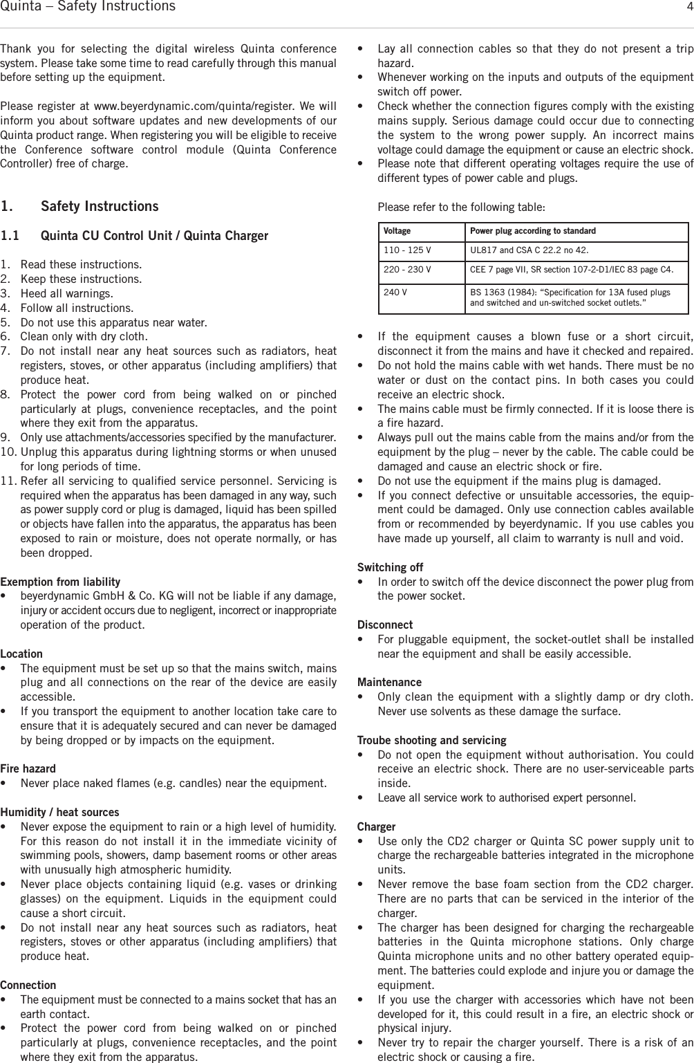
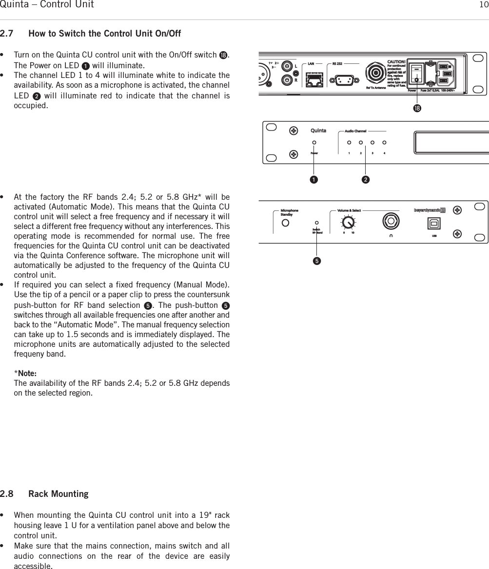
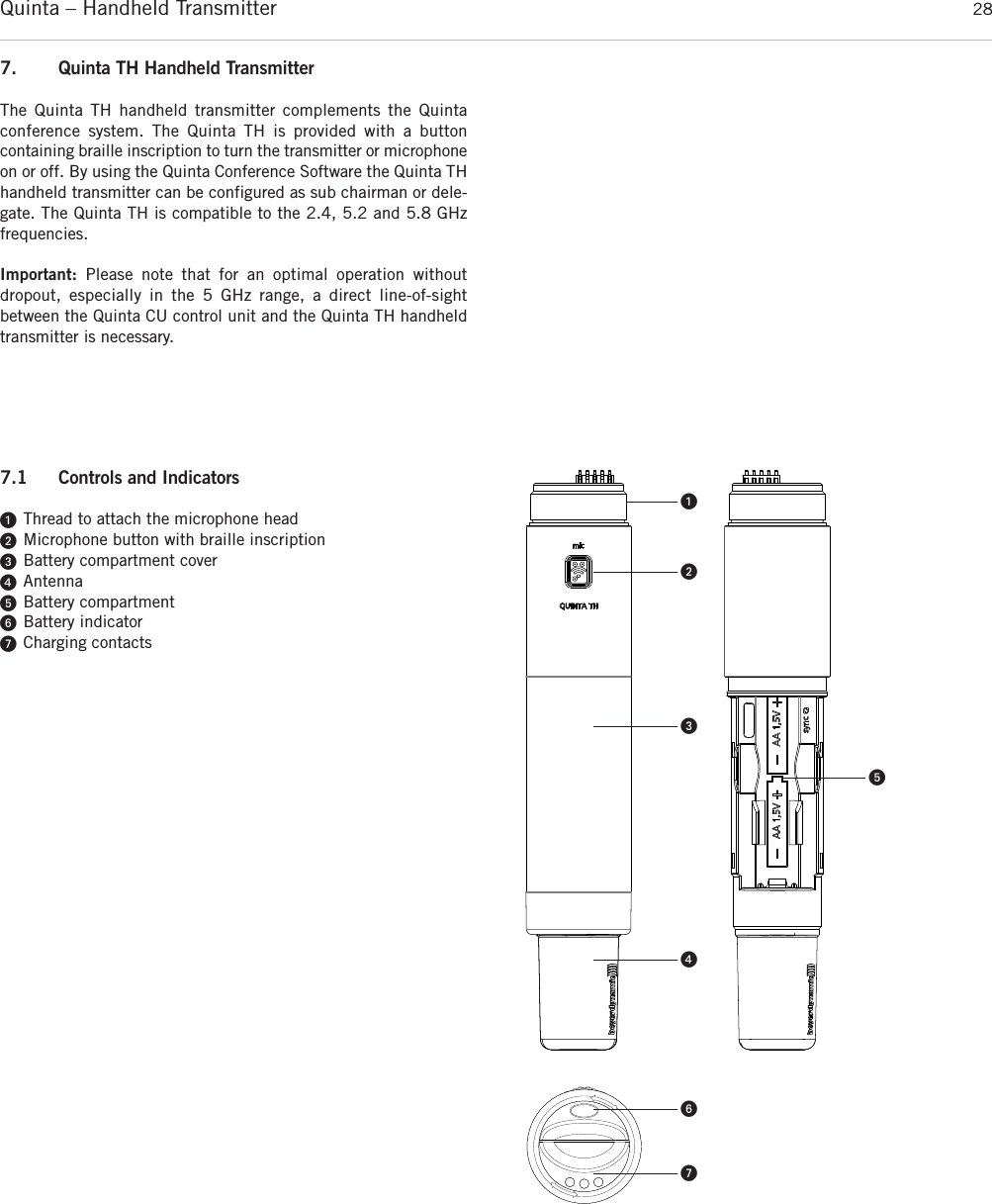
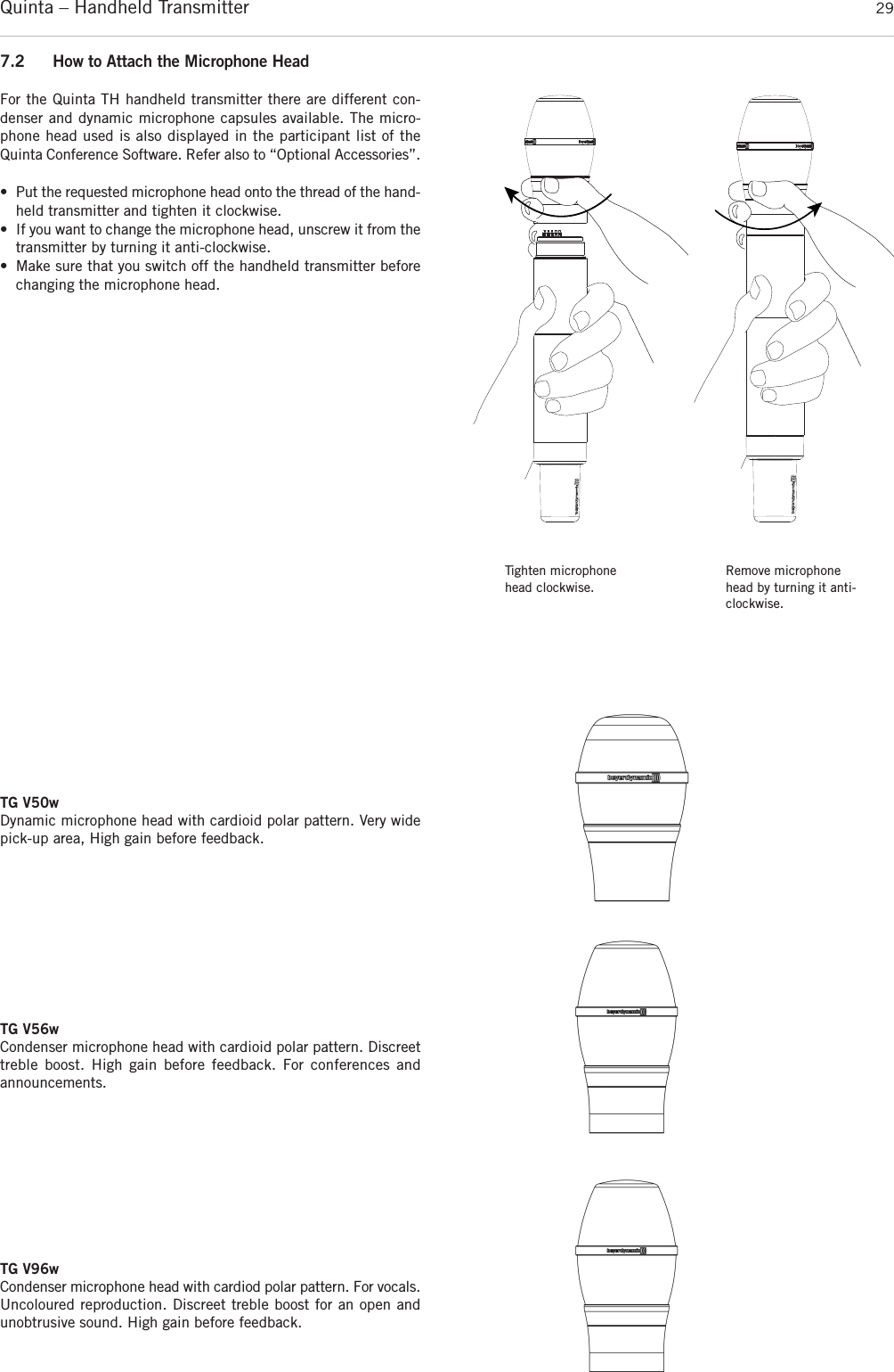
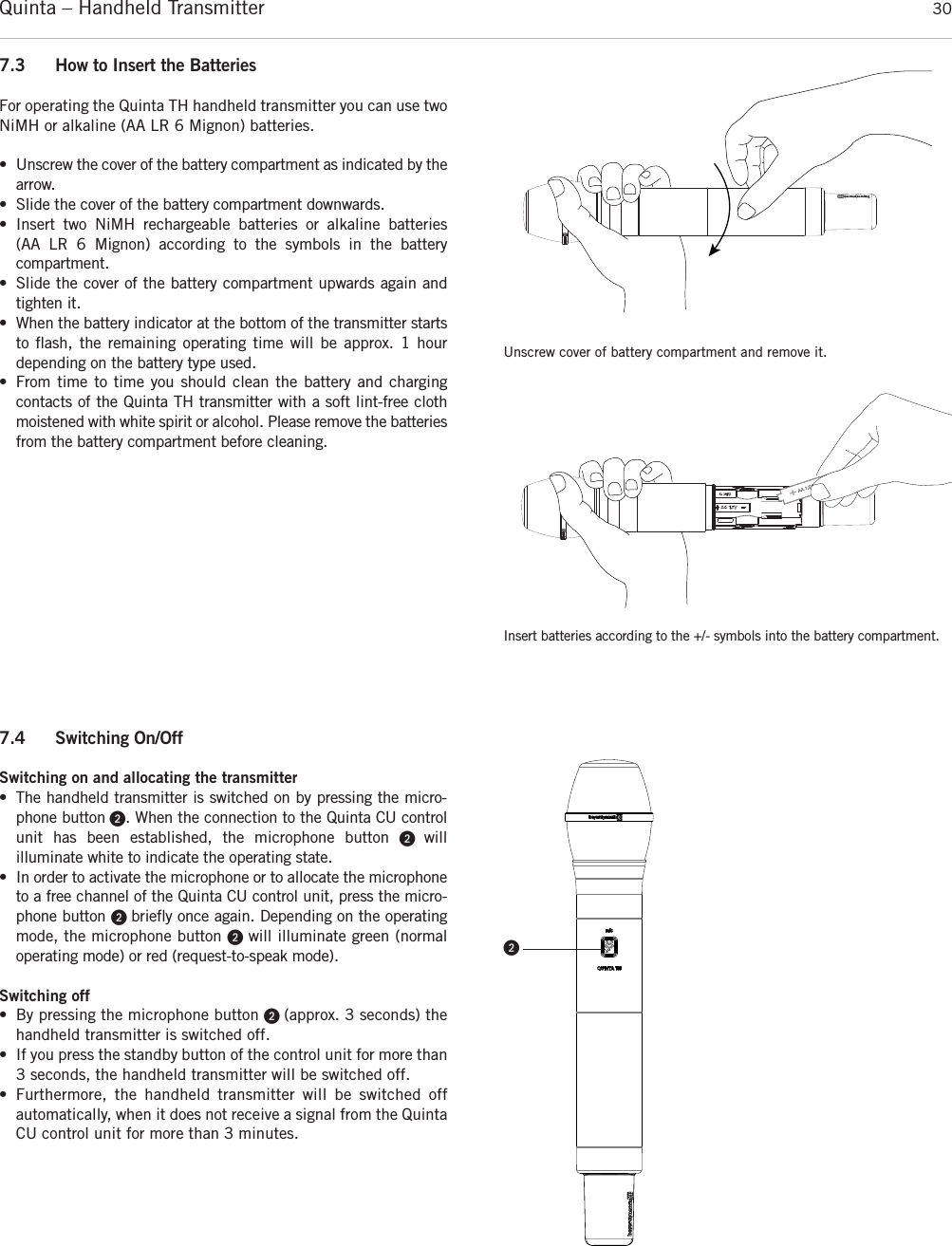
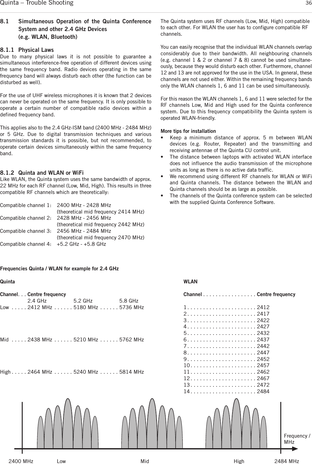
![ᕡPower on LEDᕢAudio channel LEDs 1 to 4 (white = channel vacant; red = channel occupied)ᕣDisplay to indicate operating mode, channel, headphone volumeᕤStandby button to turn off all microphone units centrallyᕥPush-button for frequency band selection ᕦVolume control for headphone / channel (The headphone volumeis set by turning the control. By pressing and turning you can select and listen to the individual channels or a mix. When pressing more than 3 seconds you will access the mainmenu of the control unit.)ᕧHeadphone connectionᕨUSB connectionᕩAntenna connectionsµAVB (Audio Video Bridging) network connection for digital audiosignals via CAT5 cables, RJ45¸Audio input (Audio IN) for the connection of external sound sources, 3-pin Phoenix terminal strip, balanced¹Audio output, individual channels, 4 x 3-pin Phoenix terminalstrips, balancedƸAudio output Mix (Master), 3-pin Phoenix terminal strips, balancedƹAudio output Mix (Master), 3-pin XLR, balanced ƺAudio output Mix (Master), RCA, unbalanced ƻLAN connection for PC / network, RJ 45ƼConnection for media control system / PC / network, RS 232ƽOn/Off switchƾFuseƿMains connectionQuinta – Control Unit 7FrontRearᕡᕩ µ ¸ ¹ Ƹ ƹ ƺ ƻ Ƽ ᕩ ƽ ƾ ƿᕢ ᕣ ᕤ ᕥ ᕦ ᕧ ᕨ2. Quinta CU Control UnitThe Quinta CU control unit is the heart of the system. It controls thedelegate and chairman microphone units. With one control unit amaximum of 4 speakers (e.g. 3 delegates and 1 chairman) can speaksimultaneously. The radio transmission is in the triple band (2.4 /5.2 / 5.8 GHz frequency band).The control unit has been designed for installations on tables or 19"rack mounting. When setting up the system, please follow the safety instructions mentioned in chapter 1. Furthermore, please note• the ambient temperature of the installation site must not exceed35 °C [95 °F]. • there must not be exceeding dust and humidity a the installationsite.• that the unit is not exposed to direct sunlight.• the connection must be protected against direct access duringoperation.• that there must be a strain relief of the cables.• the installation site must be protected against vibrations.2.1 Controls and Indicators](https://usermanual.wiki/Beyerdynamic/QUINTATH.usermanual-pdf/User-Guide-2609566-Page-7.png)
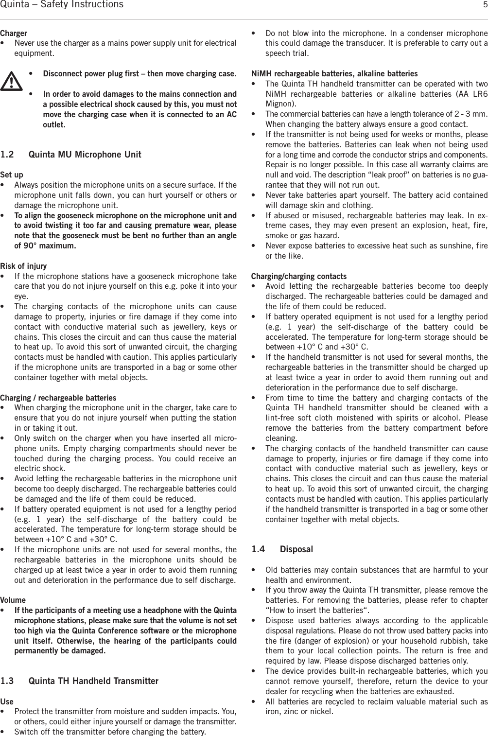
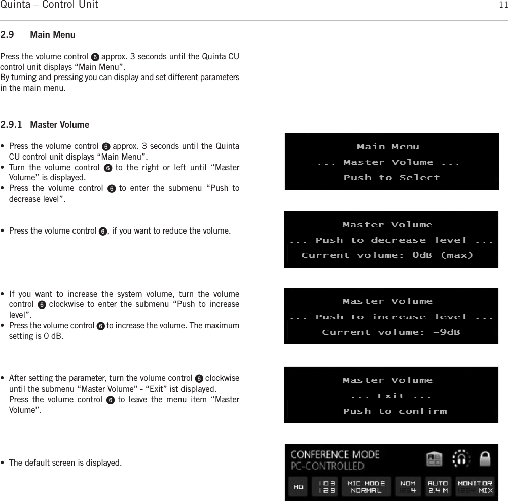
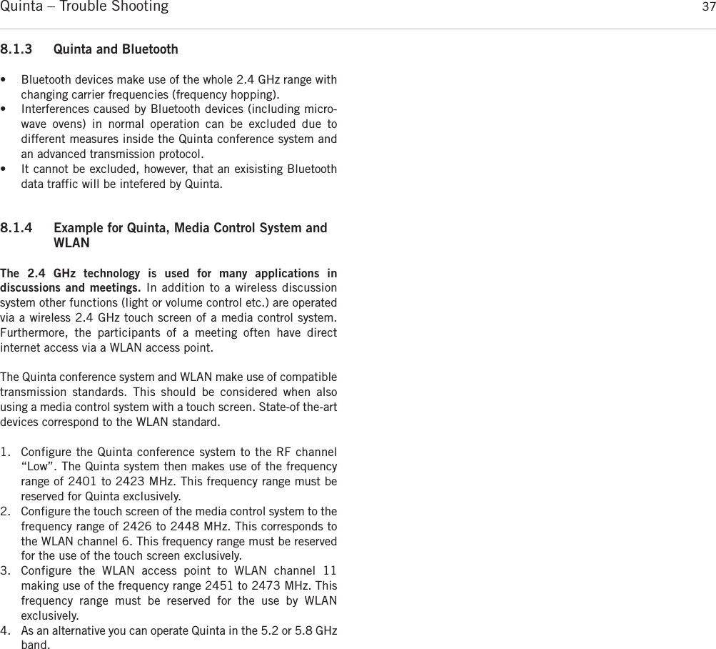
![Quinta – Control Unit 8ᕩ µ ¸ ¹ Ƹ ƹ ƺ ƻ Ƽ ᕩ ƽ ƾ ƿ2.3 How to Connect the Antennae2.3.1 Direct Connection• Connect the antennae to the antenna connections ᕩ. Pleasenote that for diversity operation both antennae have to be connected! A weighting circuit is used to make sure that the better antenna signal is received. • For stand-alone operation we recommend using the supplied CA Q 11 angled rod antennae.2.3.2 Remote Connection• The Quinta CU control unit can also be operated with remoteantennae. We recommed extremely low attenuation connectingcables which are 10 m [32.8 ft] or 20 m [65.6 ft] long. Pleasenote that the antennae have to be installed remotely. 2.2 Where to Place the Control Unit• If you do not use remote antennae, place the Quinta CU controlunit in the room where the meeting takes place. If you use remote antennae, place the antennae in the conference room.• Avoid shadowing effect of the antennae, especially by metallicsurfaces.• A free line of sight between the Quinta MU microphone units andthe antennae of the Quinta CU control unit is essential for the operation of the microphone units. Big obstacles in between canpossibly affect the radio transmission. In such specific installations the use of remote antennae can possibly achievean improvement of the RF situation.• If you want to install several Quint CU control units in a 19"rack, please make sure that there is a minimum distance of 1 Ubetween the control units to avoid interferences, especially ifyou do not use remote antennae. Important:• There must be an unobstructed path between the micro-phone units and the antennae, i.e. between the Quinta CUcontrol unit or the remote antennae and the microphoneunits there must not be any obstacles. With a free line ofsight between the control unit and the microphone unitsand the rod antennae the range is between 30 to 50 m[98.4 ft to 164 ft]. For optimum range the surface of the table is important, wood orplastic tables are ideal, but metal tables can cause interferencesand reduce the range. • Please make sure that with a free line of sight the minimum distance between the antennae and the microphone units is notless than 1 m [3.2 ft].](https://usermanual.wiki/Beyerdynamic/QUINTATH.usermanual-pdf/User-Guide-2609566-Page-8.png)
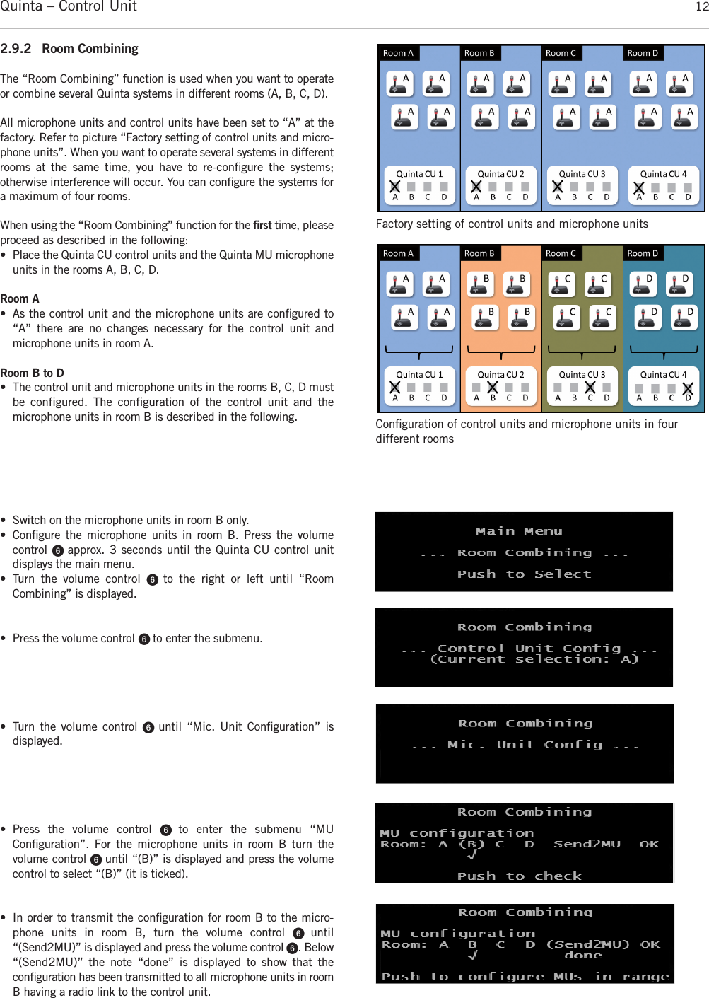
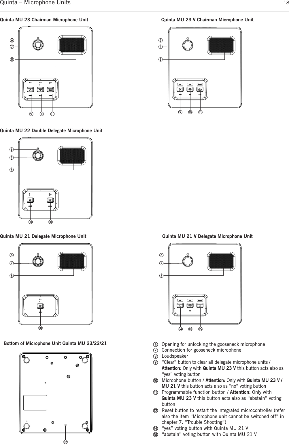
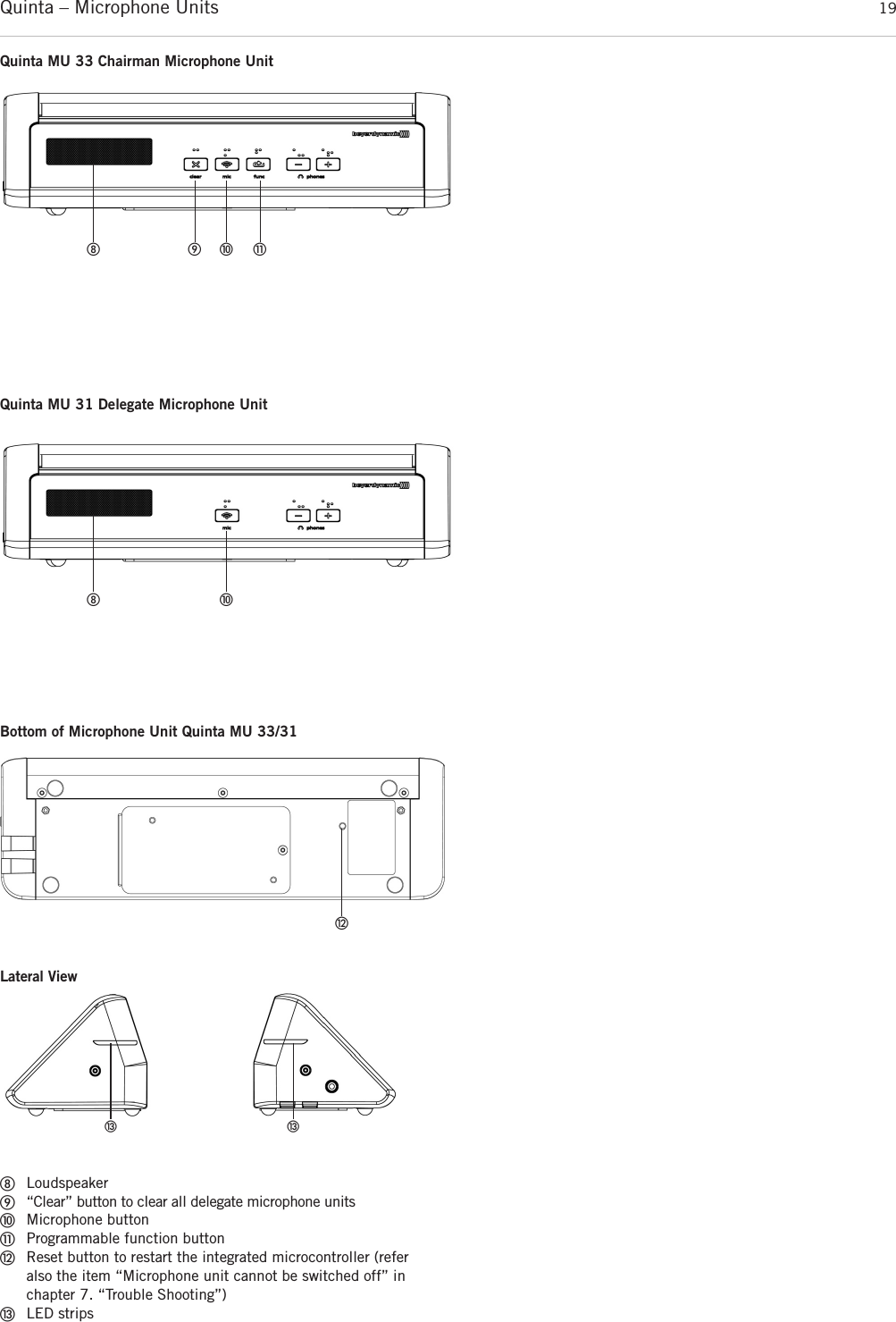
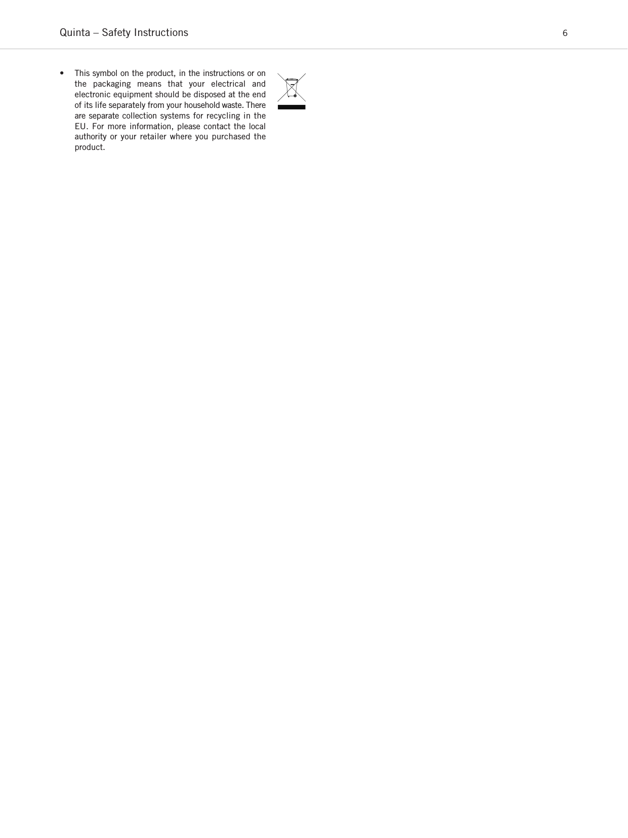
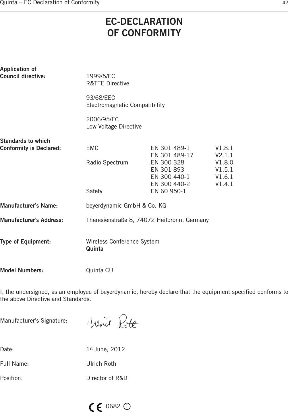
![Quinta – Microphone Units 203.2 How to Connect the Gooseneck Microphoneto Quinta MU 21/22/23The following gooseneck microphones with an LED are available toconnect to the microphone unit.– Classis GM 313 Q; 300 mm [11.81"] in length– Classis GM 314 Q; 400 mm [15.75"] in length– Classis GM 315 Q; 500 mm [19.69"] in length– Classis GM 316 Q; 600 mm [23.62"] in length• Take the gooseneck microphone by the shaft, put it into theconnection for gooseneck microphones ቨand press the shaftdownwards until it locks in place. • If you want to remove the gooseneck microphone, press intothe opening for unlocking the gooseneck microphone ቧwiththe supplied tool or a similar thin tool. Remove the gooseneckmicrophone by taking it by the shaft and pulling. 3.3 Switching On / OffHow to switch on and allocate the microphone units• The microphone unit is switched on by pressing the micro-phone button. The microphone button ቫ will light up for amoment and the operating control LED ቢ on the rear will illuminate green. When the connection to the Quinta CU control unit has been established, the buttons of the micro-phone unit will illuminate white. • To activate the microphone or to allocate the microphone unitto a free channel of the Quinta CU control unit, press the microphone button ቫ once again. Depending on the operatingmode, the microphone button will illuminate green (normaloperating mode) or red (request-to-speak mode).Switching off• By pressing the microphone button ቫ for more than 2 secondsthe microphone unit is switched off.• If you press the standby button ᕤ of the Quinta CU controlunit for more than 3 seconds, you switch off all the activeQuinta MU microphone units within the range of the QuintaCU control unit. • Furthermore, the microphone units are switched off automatically, when they do not receive a signal from theQuinta CU control unit for more than 3 minutes. ᕤ ᕥቫ ቫ ቫ ቫQuinta MU 23 Quinta MU 21Quinta MU 22Quinta MU 23 V Quinta MU 21 VQuinta MU 33ቫቫQuinta MU 31ቫ ቫ](https://usermanual.wiki/Beyerdynamic/QUINTATH.usermanual-pdf/User-Guide-2609566-Page-20.png)
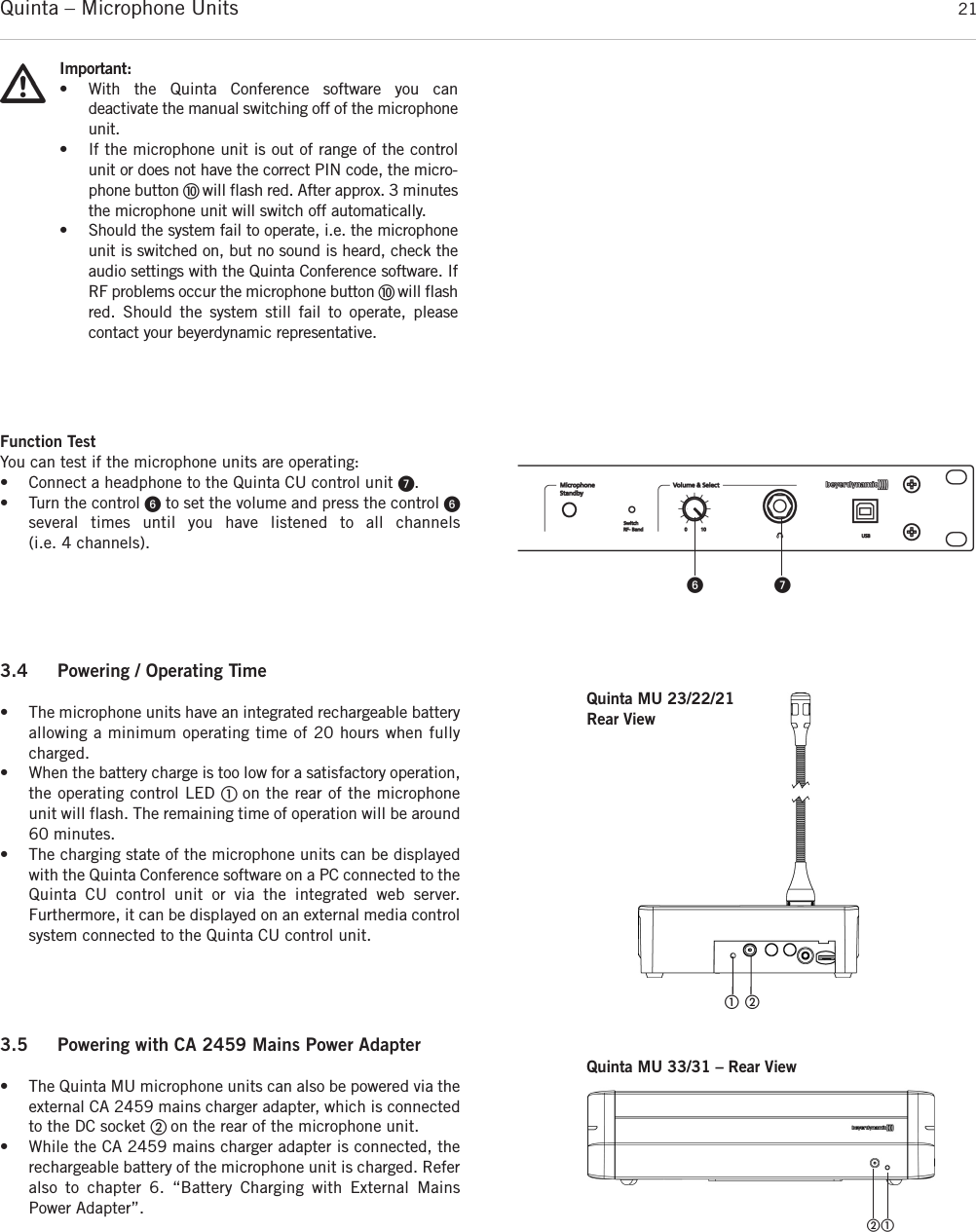
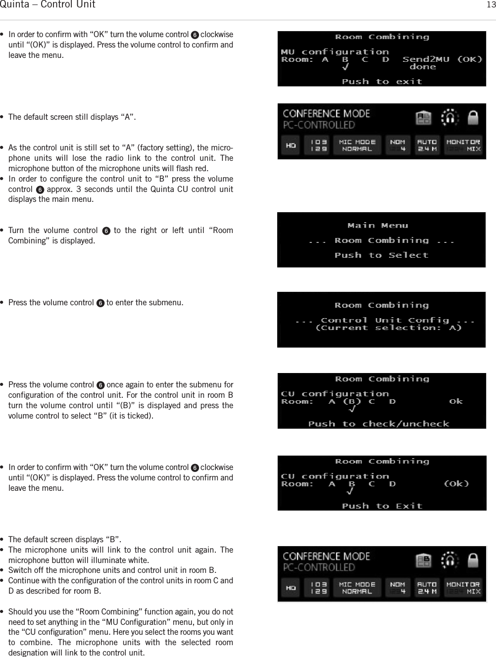
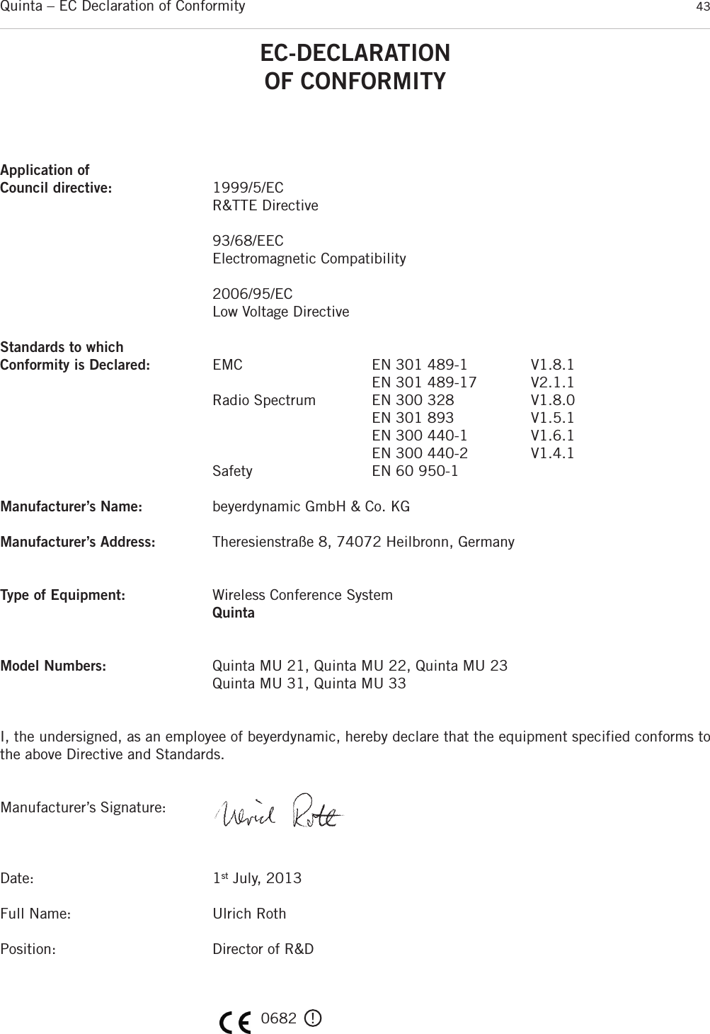
![Quinta – Charger 265.2 Notes for Microphone Units and Rechargeable Batteries• To achieve a 100% battery capacity of the rechargeable batteries,all microphone units should have 2 complete charging cycles(charging and discharging) at least. Only after several charging anddischarging cycles, the rechargeable batteries will achieve theirfull capacity.• The Quinta MU microphone units are provided with high- performance nickel-metal hydrid (NiMH) batteries. These guarantee operating times of approx. 20 hours. It takes about2.5 hours to charge them. • The service life of the batteries largely depends on the manner inwhich they are looked after and on how well the user rechargesthem. To extend the service life of the batteries for as long as possible, the following charging cycle is recommended: – Do not keep the microphone units in the charging case whenit is switched on. – Only put the microphone units in the charging case before a conference / application and fully charge them until the “fullycharged” status is shown. – In particular, when the microphone units are inserted, thecharging case should not be constantly switched on and off.For each charging cycle, there is an initial 5-minute charge tocheck the battery status. If the case with the microphone unitsis switched on every day (for example, because the mains isswitched off automatically or by a cleaner), the microphoneunits will be slowly but constantly overcharged and this will damage the batteries.– The NiMH batteries used minimise the so-called “memory effect”, but their capacity is reduced when they are only partially discharged on a regular basis. For this reason, the microphone units should be fully discharged every threemonths until they switch off automatically. They can then befully recharged. This procedure can, if necessary, be repeateda second time.– If, despite this measure, the microphone unit does not operatefor a sufficiently long period of time, the battery has reachedthe end of its service life and must be replaced. The typicalservice life of the battery is greatly dependent on whether ornot the above points are observed. This is why batteries arenot covered by warranties. If the above points are observed, abattery typically has a service life of at least two years or 500 complete charging cycles, depending on which occursfirst.Note:• If an error has occurred, try to restart the charging process. If the LEDs are still flashing rapidly, pleasecontact your beyerdynamic dealer.• For a reliable charging of the rechargeable batteries andin order to avoid long-term damages the ambient temperature must not exceed +35 °C [95 °F] duringcharging. 5. Quinta CD 2 Charger in the Quinta CC 2 | CC 2 / 600 Case and Quinta CD 3 in the Quinta CC 3 CaseQuinta CC 2 is a modular charging and transport case for the QuintaMU 23/22/21 microphone units. The basic version the Quinta CC 2 consists of a top cover (Quinta CT 2), a charger (Quinta CD 2) for 10Quinta MU 23/22/21 microphone unit and a bottom with casters (Quinta CW 2). This version is suitable for Quinta MU 23/22/21 microphone units using the Classis GM 313 Q, GM 314 Q and GM 315 Q microphones.For microphone units using the Classis GM 316 Q microphone the version Quinta CC 2 / 600 with a higher top cover (Quinta CT 2 / 600)will be available.Quinta CC 3 is a modular charging and transport case for the Quinta MU 33/31 microphone units. The basic version the Quinta CC3consists of a top cover (Quinta CT 2), a charger (Quinta CD 3) for 12Quinta MU 33/31 microphone unit and a bottom with casters (Quinta CW 2). • With the Quinta CD 2 charger integrated in the Quinta CC 2 or CC 2 / 600 case you can charge a maximum of 10 Quinta MU23/22/21 microphone units with the Classis GM 313 Q, 314 Q,315 Q or Classis GM 316 Q microphone. With the Quinta CD 3charger integrated in the Quinta CC 3 case you can charge a maximum of 12 Quinta MU 33/31 microphone units. The chargingstate can be seen from the outside through a glass panel.• The Quinta CC 2 or CC 3 charging and transport case can be extended with another Quinta CD 2 or CD 3 charger for 10 or 12microphone units. Because of a possible instability more than twoQuinta CD 2 or CD 3 chargers must not be piled up. Quinta CD 2chargers that contain microphone units with the Classis GM 316 Qmicrophone cannot be piled up because of the microphone length.• For the Quinta CC 2 or CC 2 / 600 or CC 3 charging and transportcase there is an optional compartment available for storing the Quinta CU control unit and accessories such as cables and gooseneck microphones.5.1 Charging Process1. Connect the charger to AC power and switch it on. The switchwill illuminate.2. Put the switched-off microphone units into the charging compartments. If microphone units are switched on, they areswitched off automatically. When the microphone units are usedagain, they must be switched on by hand.3. The charging process is indicated by the LED of the gooseneckand can be seen from the outside through a glass panel.LED indicator when the batteries are recharged:a) Gooseneck LED or LED strips are flashing red. . . . . . . . . . . . . . . Battery is chargedb) Gooseneck LED or LED strips illuminates red permanently. . . . . . Battery is completely fullc) Gooseneck LED or LED stripsare flashing red rapidly . . . . . . . . . Error• After some time the capacity of the rechargeable batteries is reduced technically. This will reduce the operating time.• It is normal that the rechargeable batteries are heated up duringthe charging process.• Clean the charging contacts with spirit or isopropyl alcohol fromtime to time. While cleaning avoid contact with the painted surface.](https://usermanual.wiki/Beyerdynamic/QUINTATH.usermanual-pdf/User-Guide-2609566-Page-26.png)
![Quinta – Components 3810. AccessoriesSupplied Accessories1 Power cable1 USB cable6 Phoenix terminal strips, 3-pin2 CA Q11 antennas1 Unlocking toolQuinta Conference Software for Control and Configuration . . . . . . . . . . . . . . . . . . . . . . . . . . . . . . . . . . . . . . . . . . . . Order # 723.991OptionalQuinta CU Control UnitCA Q 13 Planar antenna, 2.4 - 5.8 GHz . . . . . . . . . . . . . . . . . . . . . . . . . . . . . . . . . . . . . . . . . . . . . . . . . . Order # 724.408CA Q 14 Omnidirectional antenna for remote installation . . . . . . . . . . . . . . . . . . . . . . . . . . . . . . . . . . . . . . Order # 723.894CA Q 30 Ecoflex system coaxial cable, sold per metre. . . . . . . . . . . . . . . . . . . . . . . . . . . . . . . . . . . . . . . . . Order # 724.440CA Q 31 Ecoflex system coaxial cable, 10 m [32.8 ft] . . . . . . . . . . . . . . . . . . . . . . . . . . . . . . . . . . . . . . . . Order # 724.416CA Q 32 Ecoflex system coaxial cable, 20 m [65.6 ft] . . . . . . . . . . . . . . . . . . . . . . . . . . . . . . . . . . . . . . . . Order # 724.424Gooseneck Microphones for the Quinta MU 23/22/21 Microphone UnitsClassis GM 313 Q Gooseneck microphone, condenser, cardioid, black, length 300 mm [11.81"], LED, 5-pin XLR connector, incl. wind shield. . . . . . . . . . . . . . . . . . . . . . . . . . . . . . . . . . . . . . . . . Order # 724.203Classis GM 314 Q Gooseneck microphone, condenser, cardioid, black, length 400 mm [15.75"], LED, 5-pin XLR connector, incl. wind shield. . . . . . . . . . . . . . . . . . . . . . . . . . . . . . . . . . . . . . . . . . . . . Order # 724.211Classis GM 315 Q Gooseneck microphone, condenser, cardioid, black, length 500 mm [19.69"], LED, 5-pin XLR connector, incl. wind shield. . . . . . . . . . . . . . . . . . . . . . . . . . . . . . . . . . . . . . . . . . . . . Order # 724.238Classis GM 316 Q Gooseneck microphone, condenser, cardioid, black, length 600 mm [23.62"], LED, 5-pin XLR connector, incl. wind shield. . . . . . . . . . . . . . . . . . . . . . . . . . . . . . . . . . . . . . . . . . . . . Order # 724.351Quinta CC 2 | CC 2 / 600 Charging and Transport CaseQuinta CD 2 Charger for 10 Quinta MU 23/22/21 microphone units . . . . . . . . . . . . . . . . . . . . . . . . . . . . . . . . . Order # 723.975Quinta CM 2 19" compartment for Quinta CU control unit. . . . . . . . . . . . . . . . . . . . . . . . . . . . . . . . . . . . . . . . . Order # 724.661Quinta CT 2 Top cover . . . . . . . . . . . . . . . . . . . . . . . . . . . . . . . . . . . . . . . . . . . . . . . . . . . . . . . . . . . . . . . . . Order # 724.556Quinta CT 2/600 Top cover, when using the microphone units with the Classis GM 316 Q microphone . . . . . . . . . . . . Order # 724.580Quinta CW 2 Bottom with casters . . . . . . . . . . . . . . . . . . . . . . . . . . . . . . . . . . . . . . . . . . . . . . . . . . . . . . . . . . Order # 724.564Quinta CC 3 Charging and Transport CaseQuinta CD 3 Charger for 12 Quinta MU 33/31 microphone units. . . . . . . . . . . . . . . . . . . . . . . . . . . . . . . . . . . . Order # 725.137Quinta CM 2 19" compartment for Quinta CU control unit. . . . . . . . . . . . . . . . . . . . . . . . . . . . . . . . . . . . . . . . . Order # 724.661Quinta CT 2 Top cover . . . . . . . . . . . . . . . . . . . . . . . . . . . . . . . . . . . . . . . . . . . . . . . . . . . . . . . . . . . . . . . . . Order # 724.556Quinta CW 2 Bottom with casters . . . . . . . . . . . . . . . . . . . . . . . . . . . . . . . . . . . . . . . . . . . . . . . . . . . . . . . . . . Order # 724.5649. ComponentsQuinta CU Control unit, DSSS transmission in 2.4 / 5.2 / 5.8 GHz ISM bands,4 receive channels, 19" housing, 1 U, incl. 2 angled rod antennae,matt black, with high-resolution OLED display . . . . . . . . . . . . . . . . . . . . . . . . . . . . . . . . . . . . . . . Order # 723.924Quinta MU 23 Chairman microphone unit, removable Classis GM 31x Q gooseneck microphone (optional),DSSS transmission (Triple-RF-ISM-Band), incl. rechargeable battery, with loudspeaker and three buttons, soft touch paint, matt black . . . . . . . . . . . . . . . . . . . . . . . . . . . . . . . . . . . . . . . . . . . . . . . . . . . . Order # 723.932Quinta MU 22 Double delegate microphone unit, removable Classis GM 31x Q gooseneck microphone (optional),DSSS transmission (Triple-RF-ISM-Band), incl. rechargeable battery, with loudspeaker and two microphone buttons, soft touch paint, matt black . . . . . . . . . . . . . . . . . . . . . . . . . . . . . . . Order # 723.940Quinta MU 21 Delegate microphone unit, removable Classis GM 31x Q gooseneck microphone (optional),DSSS transmission (Triple-RF-ISM-Band), incl. rechargeable battery, with loudspeaker and one microphone button, soft touch paint, matt black . . . . . . . . . . . . . . . . . . . . . . . . . . . . . . . Order # 723.959Quinta MU 33 Chairman microphone unit, Revoluto technology, DSSS transmission (Triple-RF-ISM-Band),incl. rechargeable battery, with loudspeaker and three buttons, soft touch paint, matt black . . . . . . . Order # 725.102Quinta MU 31 Delegate microphone unit, Revoluto technology, DSSS transmission (Triple-RF-ISM-Band), incl. rechargeable battery, with loudspeaker and one microphone button, soft touch paint, matt black Order # 725.110Quinta CC 2 Charging case for 10 Quinta MU 23/22/21 microphone units with GM 313/314/315 Q, consisting of: Quinta CT 2 top cover, Quinta CD 2 charger, Quinta CW 2 bottom with casters . . . . . . . . . . . . . . . . Order # 723.967Quinta CC 2/600 Charging case for 10 Quinta MU 23/22/21 microphone units with Classis GM 316 Q, consisting of: Quinta CT 2 / 600 top cover, Quinta CD 2 charger, Quinta CW 2 bottom with casters . . . . . . . . . . . . Order # 724.580Quinta CC 3 Charging case for 12 Quinta MU 33/31 microphone units, consisting of: Quinta CT 2 top cover, Quinta CD 3 charger, Quinta CW 2 bottom with casters . . . . . . . . . . . . . . . . Order # 725.129CA 2459 Mains power adapter with charging function and DC power supply for one Quinta MU microphone unit. . Order # 729.493Quinta TH Digital handheld transmitter with metal housing, silicone button with braille inscription, withoutmicrophone head, incl. 2 x AA NiMH batteries, MKV 11 microphone clamp and bag for transport . . . Order # 729.329](https://usermanual.wiki/Beyerdynamic/QUINTATH.usermanual-pdf/User-Guide-2609566-Page-38.png)
![Quinta – Technical Specifications 39Quinta TH Handheld TransmitterInterchangeable Microphone CapsulesTG V50w Dynamic, cardioid, incl. storage bag . . . . . . . . . . . . . . . . . . . . . . . . . . . . . . . . . . . . . . . . . . . . . . Order # 711.438TG V56w Electret condenser, cardioid, incl. storage bag . . . . . . . . . . . . . . . . . . . . . . . . . . . . . . . . . . . . . . . Order # 711.446TG V96w True condenser, cardioid, incl. storage bag . . . . . . . . . . . . . . . . . . . . . . . . . . . . . . . . . . . . . . . . . . Order # 711.470ChargerWA-CD Charger for TG 1000 beltpack transmitter and Quinta TH handheld transmitter with 4 charging compartments and control via Ethernet . . . . . . . . . . . . . . . . . . . . . . . . . . . . . . . . . . . . . . . . . . . . Order # 711.14411. Technical SpecificationsGeneralFrequency range . . . . . . . . . . . . . . . . . . . . . . . . . . . . . . . 2400 – 2483.5 MHz 5150 – 5250 MHz5725 – 5875 MHzModulation . . . . . . . . . . . . . . . . . . . . . . . . . . . . . . . . . . . DSSS (Direct Sequence Spread Spectrum) andQPSK/BPSK (Quadrature/Binary Phase Shift Keying)digital signal processing acc. to own standardMax. number of audio streams . . . . . . . . . . . . . . . . . . . . . 4 useable channels per system Signal-to-noise ratio . . . . . . . . . . . . . . . . . . . . . . . . . . . . . 80 dB typ., (unweighted signal-to-noise ratio)Range between microphone units and control unit . . . . . . . > 100 m [109.36 yds]Power supply. . . . . . . . . . . . . . . . . . . . . . . . . . . . . . . . . . 100 – 240 V AC 50/60 HzApproval . . . . . . . . . . . . . . . . . . . . . . . . . . . . . . . . . . . . . world-wideAVBTransmission and reception of audio data. . . . . . . . . . . . . . . . . . . . . . . . . . . . . . . . . . acc. to IEC 61883-6Format of the audio data . . . . . . . . . . . . . . . . . . . . . . . . . AM824Stream ID Quinta CU . . . . . . . . . . . . . . . . . . . . . . . . . . . . Bit 63 – 16 / MAC address Bit 15 – 0 / X Quinta MU 23/22/21 Microphone UnitsTransmitter power . . . . . . . . . . . . . . . . . . . . . . . . . . . . . . max. 20 dBm per channel and region (average, duty cycle ≤ 30%)*Battery voltage . . . . . . . . . . . . . . . . . . . . . . . . . . . . . . . . 8 NiMH cells, 2080 mAhExternal DC operation . . . . . . . . . . . . . . . . . . . . . . . . . . . 15 V DC (±0.5 V), residual hum < 20 mV, 950 mA Charging time with charger . . . . . . . . . . . . . . . . . . . . . . . . max. 2.5 hours when the battery is completely emptywith mains charger adapter. . . . . . . . . . . . . . . . . . . . . . . . max. 2.5 hours when the battery is completely emptyLoudspeaker . . . . . . . . . . . . . . . . . . . . . . . . . . . . . . . . . . Wide-band, integrated loudspeakerVolume decrease when Mic On (“Ducking”) . . . . . . . . . . . . 15 dB fixed settingHeadphone output . . . . . . . . . . . . . . . . . . . . . . . . . . . . . . Jack socket (3.5 mm, stereo)Min. impedance . . . . . . . . . . . . . . . . . . . . . . . . . . . . . . . 16 ΩPower supply. . . . . . . . . . . . . . . . . . . . . . . . . . . . . . . . . . 9.6 V with integrated NiMH battery (8 cells) Operating time depending on the type ofthe microphone unit. . . . . . . . . . . . . . . . . . . . . . . . . . . . . approx. 20 hours in discussion mode, operating time also depends on thevolume Temperature range (at < 90% humidity). . . . . . . . . . . . . . . +10° – +40°C [+50 °F – +104 °F] Storage temperature (at < 90% humidity) . . . . . . . . . . . . . -20° – +55°C [-4 °F – +131 °F] Dimensions (without microphone) . . . . . . . . . . . . . . . . . . . Length 173 mm [6.8"]Width 157 mm [6.18"]Height 51 mm [2.01"]Weight . . . . . . . . . . . . . . . . . . . . . . . . . . . . . . . . . . . . . . 1.7 kg [3.74 lbs]Quinta MU 33/31 Microphone UnitsTransmitter power . . . . . . . . . . . . . . . . . . . . . . . . . . . . . . max. 20 dBm per channel (average, duty cycle ≤ 30%)*Battery voltage . . . . . . . . . . . . . . . . . . . . . . . . . . . . . . . . 8 NiMH cells, 2080 mAh External DC operation . . . . . . . . . . . . . . . . . . . . . . . . . . . 15 V DC (±0.5 V), residual hum < 20 mV, 400 mACharging time with charger . . . . . . . . . . . . . . . . . . . . . . . . max. 2.5 hours when the battery is completely emptywith mains charger adapter. . . . . . . . . . . . . . . . . . . . . . . . max. 2.5 hours when the battery is completely emptyMicrophone. . . . . . . . . . . . . . . . . . . . . . . . . . . . . . . . . . . Microphone ArrayPick up pattern . . . . . . . . . . . . . . . . . . . . . . . . . . . . . . . . CorridorT.H.D.. . . . . . . . . . . . . . . . . . . . . . . . . . . . . . . . . . . . . . . < 0.1%Loudspeaker . . . . . . . . . . . . . . . . . . . . . . . . . . . . . . . . . . Integrated, two-way loudspeaker Loudspeaker switch off at “Mic On” . . . . . . . . . . . . . . . . . yesHeadphone output . . . . . . . . . . . . . . . . . . . . . . . . . . . . . . . . jack socket (3.5 mm, stereo) Min. impedance . . . . . . . . . . . . . . . . . . . . . . . . . . . . . . . 16 ΩPower supply. . . . . . . . . . . . . . . . . . . . . . . . . . . . . . . . . . 9.6 V with integrated NiMH battery (8 cells)](https://usermanual.wiki/Beyerdynamic/QUINTATH.usermanual-pdf/User-Guide-2609566-Page-39.png)
![Quinta – Technical Specifications 40Operating time depending on the type of the microphone unit . . . . . . . . . . . . . . . . . . . . . . . . . . . approx. 20 hours in discussion mode; operating time depends on the volume Temperature range (at < 90% humidity). . . . . . . . . . . . . . . +10° – +40°C [+50 °F – +104 °F]Storage temperature (at < 90% humidity) . . . . . . . . . . . . . 20° – +55°C [-4 °F – +131 °F] Dimensions . . . . . . . . . . . . . . . . . . . . . . . . . . . . . . . . . . . Length 96 mm [3.8"]Width 300 mm [11.8"]Height 82 mm [3.2"]Weight . . . . . . . . . . . . . . . . . . . . . . . . . . . . . . . . . . . . . . 1.06 kg [2.33 lbs]Quinta TH Handheld TransmitterOperating principle . . . . . . . . . . . . . . . . . . . . . . . . . . . . . Digital triple band handheld transmitterFrequency range . . . . . . . . . . . . . . . . . . . . . . . . . . . . . . . 2400 – 2483.5 MHz5150 – 5250 MHz5725 – 5875 MHzModulation . . . . . . . . . . . . . . . . . . . . . . . . . . . . . . . . . . . DSSS (Direct Sequence Spread Spectrum) andQPSK/BPSK (Quadrature/ Binary Phase Shift Keying)digital signal processing acc. to own standardsMax. number of audio streams . . . . . . . . . . . . . . . . . . . . . 4 usable channels per systemSignal-to-noise ratio . . . . . . . . . . . . . . . . . . . . . . . . . . . . . 80 dB typ., (unweighted signal-to-noise ratio)Range between handheld transmitter and control unit . . . . . > 100 m [109.36 yds] with a direct line of sight . . . . . . . . . . . . . . . . . . . . . . . . . . . . . . . . . . . . . . . . . . . (depending on the frequency band)Power supply. . . . . . . . . . . . . . . . . . . . . . . . . . . . . . . . . . 100 – 240 V AC 50/60 HzApproval . . . . . . . . . . . . . . . . . . . . . . . . . . . . . . . . . . . . . world-wideTransmitter power . . . . . . . . . . . . . . . . . . . . . . . . . . . . . . max. 20 dBm per channel and region (average, duty cycle ≤ 30%)*Max. SPL . . . . . . . . . . . . . . . . . . . . . . . . . . . . . . . . . . . . 107 dBU SPL @ 1% THD (with TG V56w)Internal PGA . . . . . . . . . . . . . . . . . . . . . . . . . . . . . . . . . . +25 dBPower supply. . . . . . . . . . . . . . . . . . . . . . . . . . . . . . . . . . 2.4 V via 2x AA NiMH batteries3 V via 2x AA alkaline batteriesOperating time . . . . . . . . . . . . . . . . . . . . . . . . . . . . . . . . approx. 10 hrs (depending on the battery type and frequency band)Charging time . . . . . . . . . . . . . . . . . . . . . . . . . . . . . . . . . max. 2.5 hours when the battery is completely emptyTemperature range (at < 90% humidity). . . . . . . . . . . . . . . +10° – +40°C [+50 °F – +104 °F] Storage temperature (at < 90% humidity) . . . . . . . . . . . . . -20° – +55°C [-4 °F – +131 °F] Dimensions . . . . . . . . . . . . . . . . . . . . . . . . . . . . . . . . . . . Length 197 mm [7.76"] / Ø 36 mm [1.42"] (without microphone head)Weight . . . . . . . . . . . . . . . . . . . . . . . . . . . . . . . . . . . . . . 161 g [5.68 ozs] (without batteries and microphone head)Quinta CU Control UnitFrequency response . . . . . . . . . . . . . . . . . . . . . . . . . . . . . 70 Hz – 22 kHz (-3 dB)Operation mode . . . . . . . . . . . . . . . . . . . . . . . . . . . . . . . . Diversity (receiver), separatefor each channelAntenna connection . . . . . . . . . . . . . . . . . . . . . . . . . . . . . 2 N-connectors (female)Transmitting power. . . . . . . . . . . . . . . . . . . . . . . . . . . . . . max. 20 dBm per channel and region (average, duty cycle ≤ 30%)*ConnectionsSerial control port . . . . . . . . . . . . . . . . . . . . . . . . . . . . . . RS 232, USBEthernet port. . . . . . . . . . . . . . . . . . . . . . . . . . . . . . . . . . LAN, TCP/IP standardMaster output balanced . . . . . . . . . . . . . . . . . . . . . . . . . . 1 x XLR, 1 x 3-pin Phoenix terminal strip, max. +6 dBu,level adjustable via software (range ±15 dB)Master output unbalanced . . . . . . . . . . . . . . . . . . . . . . . . RCA, max. +2.2 dBu, level adjustable via software (range ±15 dB)Audio outputs, single channels . . . . . . . . . . . . . . . . . . . . . 4 x 3-pin Phoenix terminal strip, max. +6 dBu, level adjustable via software (range 0 ... -50 dB)Input balanced . . . . . . . . . . . . . . . . . . . . . . . . . . . . . . . . 1 x 3-pin Phoenix terminal strip, max. +6 dBu, input adjustable via software(range 0 ... -50 dB)Power supply. . . . . . . . . . . . . . . . . . . . . . . . . . . . . . . . . . 100 – 240 V AC 50/60 Hz 70 – 150 mAFuse. . . . . . . . . . . . . . . . . . . . . . . . . . . . . . . . . . . . . . . . 2 x AL 0.5 A (slow blow)Power consumption . . . . . . . . . . . . . . . . . . . . . . . . . . . . . 10 VA Temperature range . . . . . . . . . . . . . . . . . . . . . . . . . . . . . . +10° – +40 °C [+50 °F – +104 °F] (at < 90% humidity)Indication . . . . . . . . . . . . . . . . . . . . . . . . . . . . . . . . . . . . 4 channel LEDs (red/white) and Power LED (red/white)Min. depth of Rack . . . . . . . . . . . . . . . . . . . . . . . . . . . . . 380 mmDimensions (W x H x D) . . . . . . . . . . . . . . . . . . . . . . . . . . 19", 1HU (440 x 44 x 239 mm) [17.32" x 1.73" x 9.41"]Weight . . . . . . . . . . . . . . . . . . . . . . . . . . . . . . . . . . . . . . 3.2 kg [7.05 lbs]AVB interface:Stream ID . . . . . . . . . . . . . . . . . . . . . . . . . . . . . . . . . . . . Bit 63 – 16 / MAC address Bit 15 – 0 / X Number of channels. . . . . . . . . . . . . . . . . . . . . . . . . . . . . 4Audio format . . . . . . . . . . . . . . . . . . . . . . . . . . . . . . . . . . IEC 61883-6/AM824 with 24-bit / 48 kHzIP configuration. . . . . . . . . . . . . . . . . . . . . . . . . . . . . . . . DHCP](https://usermanual.wiki/Beyerdynamic/QUINTATH.usermanual-pdf/User-Guide-2609566-Page-40.png)
![Quinta – Technical Specifications 41Quinta CD 2 / CD 3 Charger Power supply . . . . . . . . . . . . . . . . . . . . . . . . . . . . . . . . . . . . 100 - 240 V AC ˜, 50 / 60 HzFuse at the mains socket . . . . . . . . . . . . . . . . . . . . . . . . . 2 x 6.3 A (slow blow)Power consumption . . . . . . . . . . . . . . . . . . . . . . . . . . . . . max. 180 WMax. ambient temperature when charging (< 90% atmospheric humidity) . . . . . . . . . . . . . . . . . . . . . +10 °C – +35 °C [+50 °F – +95 °F]Storage temperature. . . . . . . . . . . . . . . . . . . . . . . . . . . . . -20 °C – +55 °C [-4 °F – +131 °F]Charging unit . . . . . . . . . . . . . . . . . . . . . . . . . . . . . . . . . 10 microphone units parallelCharging time . . . . . . . . . . . . . . . . . . . . . . . . . . . . . . . . . max. 3.5 hours when the battery is completely emptyDimensions (W x H x D) . . . . . . . . . . . . . . . . . . . . . . . . . . 757 x 476 x 370 mm [29.8" x 18.74" x 14.57"]Weight . . . . . . . . . . . . . . . . . . . . . . . . . . . . . . . . . . . . . . approx. 12 kgCA 2459 Mains Power Adapter Voltage . . . . . . . . . . . . . . . . . . . . . . . . . . . . . . . . . . . . . . 15 V DCCurrent carrying capacity . . . . . . . . . . . . . . . . . . . . . . . . . 1.6 AInput voltage . . . . . . . . . . . . . . . . . . . . . . . . . . . . . . . . . . 100 – 240 V AC 50/60 HzConnector . . . . . . . . . . . . . . . . . . . . . . . . . . . . . . . . . . . . Adapter for Europe, USA, UK, Australia*The transmitter power can differ from this value due to specific regulations in various countries.](https://usermanual.wiki/Beyerdynamic/QUINTATH.usermanual-pdf/User-Guide-2609566-Page-41.png)
![Quinta – FCC Regulation 45FCC RegulationFCC ID: OSDQUINTACU for Quinta CUFCC ID: OSDQUINTAMU2X for Quinta MU 21FCC ID: OSDQUINTAMU2X for Quinta MU 22FCC ID: OSDQUINTAMU2X for Quinta MU 23FCC ID: OSDQUINTAMU3X for Quinta MU 31FCC ID: OSDQUINTAMU3X for Quinta MU 33FCC ID: OSDQUINTATH for Quinta THCanada: IC: 3628A-QUINTACU for Quinta CUCanada: IC: 3628A-QUINTAMU2X for Quinta MU 21Canada: IC: 3628A-QUINTAMU2X for Quinta MU 22Canada: IC: 3628A-QUINTAMU2X for Quinta MU 23Canada: IC: 3628A-QUINTAMU3X for Quinta MU 31Canada: IC: 3628A-QUINTAMU3X for Quinta MU 33Canada: IC: 3628A-QUINTATH for Quinta THPart 15.19 StatementNOTICE:This device complies with Part 15 of the FCC Rules [and with Industry Canada licence-exempt RSS standard(s)].Operation is subject to the following two conditions:(1) this device may not cause harmful interference, and(2) this device must accept any interference received, including interference that may cause undesired operation.Le présent appareil est conforme aux CNR d'Industrie Canada applicables aux appareils radioexempts de licence. L’exploitation est autorisée aux deux conditions suivantes:(1) l’appareil ne doit pas produire de brouillage, et (2) l’utilisateur de l'appareil doit accepter tout brouillage radioélectrique subi, même si le brouillage est susceptible d’en compromettre le fonctionnement.Part 15.21 StatementNOTICE:Changes or modifications made to this equipment not expressly approved by beyerdynamic GmbH & Co. KG may void the FCC authorizationto operate this equipment.Part 15.105 StatementNOTE: This equipment has been tested and found to comply with the limits for a Class B digital device, pursuant to Part 15 of the FCC Rules.These limits are designed to provide reasonable protection against harmful interference in a residential installation. This equipment gene-rates, uses and can radiate radio frequency energy and, if not installed and used in accordance with the instructions, may cause harmfulinterference to radio communications. However, there is no guarantee that interference will not occur in a particular installation. If this equip-ment does cause harmful interference to radio or television reception, which can be determined by turning the equipment off and on, theuser is encouraged to try to correct the interference by one or more of the following measures:• Reorient or relocate the receiving antenna.• Increase the separation between the equipment and receiver.• Connect the equipment into an outlet on a circuit different from that to which the receiver is connected.• Consult the dealer or an experienced radio/TV technician for help.RF Exposure StatementRadiofrequency radiation exposure Information:This equipment complies with FCC radiation exposure limits set forth for an uncontrolled environment.This equipment should be installed and operated with minimum distance of 20 cm between the radiator and your body.This transmitter must not be co-located or operating in conjunction with any other antenna or transmitter.Special instructions for Japan:Operation of these devices in the 5.8GHz range is illegal in Japan.The CA Q 13 and CA Q 14 antenna may only be operated with at least 10m cable between antenna and control unit.This device is granted pursuant to the Japanese Radio Law (電波法) and the Japanese Telecommunications Business Law (電気通信事業法)•本製品は、電波法および電気通信事業法に基づき許可されています。• This device should not be modified (otherwise the granted designation number will become invalid) (refer to attached Instruction File Japan(R&T) 2012)).](https://usermanual.wiki/Beyerdynamic/QUINTATH.usermanual-pdf/User-Guide-2609566-Page-45.png)