Beyerdynamic QUINTATH Quinta TH - Handheld transmitter for Quinta conference system User Manual Quinta System BA EN mit Revoluto A7
Beyerdynamic Quinta TH - Handheld transmitter for Quinta conference system Quinta System BA EN mit Revoluto A7
Contents
- 1. usermanual.pdf
- 2. usermanual-2.pdf
- 3. UserManual.pdf
- 4. UserManual-2.pdf
UserManual.pdf

Quinta
DIGITAL WIRELESS CONFERENCE SYSTEM
Operating Instructions

Quinta – Contents 2
1. Safety Instructions . . . . . . . . . . . . . . . . . . . . . . . . . . . . . . . . . . . . . . . . . . . . . . . . . . . . . . . . . . . . . . Page 4
1.1 Quinta CU Control Unit / Quinta Charger . . . . . . . . . . . . . . . . . . . . . . . . . . . . . . . . . . . . . . . . Page 4
1.2 Quinta MU Microphone Unit . . . . . . . . . . . . . . . . . . . . . . . . . . . . . . . . . . . . . . . . . . . . . . . . . Page 5
1.3 Quinta TH Handheld Transmitter . . . . . . . . . . . . . . . . . . . . . . . . . . . . . . . . . . . . . . . . . . . . . . Page 5
1.4 Disposal . . . . . . . . . . . . . . . . . . . . . . . . . . . . . . . . . . . . . . . . . . . . . . . . . . . . . . . . . . . . . . . Page 5
2. Quinta CU Control Unit . . . . . . . . . . . . . . . . . . . . . . . . . . . . . . . . . . . . . . . . . . . . . . . . . . . . . . . . . . . Page 7
2.1 Controls and Indicators. . . . . . . . . . . . . . . . . . . . . . . . . . . . . . . . . . . . . . . . . . . . . . . . . . . . . Page 7
2.2 Where to Place the Control Unit . . . . . . . . . . . . . . . . . . . . . . . . . . . . . . . . . . . . . . . . . . . . . . Page 8
2.3 How to Connect the Antennae . . . . . . . . . . . . . . . . . . . . . . . . . . . . . . . . . . . . . . . . . . . . . . . . Page 8
2.3.1 Direct Connection . . . . . . . . . . . . . . . . . . . . . . . . . . . . . . . . . . . . . . . . . . . . . . . . . . . Page 8
2.3.2 Remote Connection . . . . . . . . . . . . . . . . . . . . . . . . . . . . . . . . . . . . . . . . . . . . . . . . . . Page 8
2.4 Audio Connection. . . . . . . . . . . . . . . . . . . . . . . . . . . . . . . . . . . . . . . . . . . . . . . . . . . . . . . . . Page 9
2.5 Power Supply. . . . . . . . . . . . . . . . . . . . . . . . . . . . . . . . . . . . . . . . . . . . . . . . . . . . . . . . . . . . Page 9
2.6 Connection of Media Control System and PC. . . . . . . . . . . . . . . . . . . . . . . . . . . . . . . . . . . . . . Page 9
2.7 How to Switch the Control Unit On/Off . . . . . . . . . . . . . . . . . . . . . . . . . . . . . . . . . . . . . . . . . . Page 10
2.8 Rack Mounting . . . . . . . . . . . . . . . . . . . . . . . . . . . . . . . . . . . . . . . . . . . . . . . . . . . . . . . . . . Page 10
2.9 Main Menu . . . . . . . . . . . . . . . . . . . . . . . . . . . . . . . . . . . . . . . . . . . . . . . . . . . . . . . . . . . . . Page 11
2.9.1 Master Volume . . . . . . . . . . . . . . . . . . . . . . . . . . . . . . . . . . . . . . . . . . . . . . . . . . . . . Page 11
2.9.2 Room Combining . . . . . . . . . . . . . . . . . . . . . . . . . . . . . . . . . . . . . . . . . . . . . . . . . . . . Page 12
2.9.3 Ethernet Info. . . . . . . . . . . . . . . . . . . . . . . . . . . . . . . . . . . . . . . . . . . . . . . . . . . . . . . Page 15
2.9.4 AVB Info . . . . . . . . . . . . . . . . . . . . . . . . . . . . . . . . . . . . . . . . . . . . . . . . . . . . . . . . . . Page 16
2.9.5 RF-Analyzer . . . . . . . . . . . . . . . . . . . . . . . . . . . . . . . . . . . . . . . . . . . . . . . . . . . . . . . Page 16
2.9.6 Firmware Versions . . . . . . . . . . . . . . . . . . . . . . . . . . . . . . . . . . . . . . . . . . . . . . . . . . . Page 16
3. Quinta MU Microphone Units . . . . . . . . . . . . . . . . . . . . . . . . . . . . . . . . . . . . . . . . . . . . . . . . . . . . . . Page 17
3.1 Controls and Indicators. . . . . . . . . . . . . . . . . . . . . . . . . . . . . . . . . . . . . . . . . . . . . . . . . . . . . Page 17
3.2 How to Connect the Gooseneck Microphone . . . . . . . . . . . . . . . . . . . . . . . . . . . . . . . . . . . . . . Page 20
3.3 Switching On/Off . . . . . . . . . . . . . . . . . . . . . . . . . . . . . . . . . . . . . . . . . . . . . . . . . . . . . . . . . Page 20
3.4 Powering / Operating Time . . . . . . . . . . . . . . . . . . . . . . . . . . . . . . . . . . . . . . . . . . . . . . . . . . Page 21
3.5 Powering with CA 2459 Mains Power Adapter. . . . . . . . . . . . . . . . . . . . . . . . . . . . . . . . . . . . . Page 21
3.6 Operating Modes . . . . . . . . . . . . . . . . . . . . . . . . . . . . . . . . . . . . . . . . . . . . . . . . . . . . . . . . . Page 22
3.6.1 Normal Operating Mode . . . . . . . . . . . . . . . . . . . . . . . . . . . . . . . . . . . . . . . . . . . . . . . Page 22
3.6.2 FiFo Mode. . . . . . . . . . . . . . . . . . . . . . . . . . . . . . . . . . . . . . . . . . . . . . . . . . . . . . . . . Page 22
3.6.3 Push-To-Talk Mode. . . . . . . . . . . . . . . . . . . . . . . . . . . . . . . . . . . . . . . . . . . . . . . . . . . Page 22
3.6.4 Voice Activation Mode . . . . . . . . . . . . . . . . . . . . . . . . . . . . . . . . . . . . . . . . . . . . . . . . Page 22
3.7 Maintenance of the Microphone Units . . . . . . . . . . . . . . . . . . . . . . . . . . . . . . . . . . . . . . . . . . Page 23
4. Programmable Functions of the Microphone Units with the Quinta Conference Software . . . . . . . . . . . . . Page 23
4.1 Security Code . . . . . . . . . . . . . . . . . . . . . . . . . . . . . . . . . . . . . . . . . . . . . . . . . . . . . . . . . . . Page 23
4.2 Programmable Function Button of the Chairman Microphone Unit . . . . . . . . . . . . . . . . . . . . . . Page 23
4.3 Request-To-Talk Mode . . . . . . . . . . . . . . . . . . . . . . . . . . . . . . . . . . . . . . . . . . . . . . . . . . . . . Page 25
5. Quinta CD 2 Charger in the Quinta CC 2 | CC 2 / 600 Case. . . . . . . . . . . . . . . . . . . . . . . . . . . . . . . . . . Page 26
5.1 How to Use the Charger . . . . . . . . . . . . . . . . . . . . . . . . . . . . . . . . . . . . . . . . . . . . . . . . . . . . Page 26
5.2 Charging Process . . . . . . . . . . . . . . . . . . . . . . . . . . . . . . . . . . . . . . . . . . . . . . . . . . . . . . . . . Page 26
6. Battery Charging with External Mains Power Adapter . . . . . . . . . . . . . . . . . . . . . . . . . . . . . . . . . . . . . . Page 27
7. Quinta TH Handheld Transmitter . . . . . . . . . . . . . . . . . . . . . . . . . . . . . . . . . . . . . . . . . . . . . . . . . . . . Page 28
7.1 Controls and Indicators. . . . . . . . . . . . . . . . . . . . . . . . . . . . . . . . . . . . . . . . . . . . . . . . . . . . . Page 28
7.2 How to Attach the Microphone Head . . . . . . . . . . . . . . . . . . . . . . . . . . . . . . . . . . . . . . . . . . . Page 29
7.3 How to Insert the Batteries . . . . . . . . . . . . . . . . . . . . . . . . . . . . . . . . . . . . . . . . . . . . . . . . . . Page 30
7.4 Switching On/Off . . . . . . . . . . . . . . . . . . . . . . . . . . . . . . . . . . . . . . . . . . . . . . . . . . . . . . . . . Page 31
7.5 Operating Modes . . . . . . . . . . . . . . . . . . . . . . . . . . . . . . . . . . . . . . . . . . . . . . . . . . . . . . . . . Page 31
7.6 Maintenance . . . . . . . . . . . . . . . . . . . . . . . . . . . . . . . . . . . . . . . . . . . . . . . . . . . . . . . . . . . . Page 32
7.7 Charging . . . . . . . . . . . . . . . . . . . . . . . . . . . . . . . . . . . . . . . . . . . . . . . . . . . . . . . . . . . . . . . Page 33
8. Trouble Shooting . . . . . . . . . . . . . . . . . . . . . . . . . . . . . . . . . . . . . . . . . . . . . . . . . . . . . . . . . . . . . . . Page 34
8.1 Simultaneous Operation of the Quinta Conference System and other 2.4 GHz Devices . . . . . . . . Page 36
8.1.1 Physical Laws . . . . . . . . . . . . . . . . . . . . . . . . . . . . . . . . . . . . . . . . . . . . . . . . . . . . . . Page 36
8.1.2 Quinta and WLAN or WiFi. . . . . . . . . . . . . . . . . . . . . . . . . . . . . . . . . . . . . . . . . . . . . . Page 36
8.1.3 Quinta and Bluetooth . . . . . . . . . . . . . . . . . . . . . . . . . . . . . . . . . . . . . . . . . . . . . . . . . Page 37
8.1.4 Example for Quinta, Media Control System and WLAN. . . . . . . . . . . . . . . . . . . . . . . . . . Page 37

Quinta – Contents 3
9. Components. . . . . . . . . . . . . . . . . . . . . . . . . . . . . . . . . . . . . . . . . . . . . . . . . . . . . . . . . . . . . . . . . . . Page 38
10 Accessories . . . . . . . . . . . . . . . . . . . . . . . . . . . . . . . . . . . . . . . . . . . . . . . . . . . . . . . . . . . . . . . . . . . Page 38
11. Technical Specifications . . . . . . . . . . . . . . . . . . . . . . . . . . . . . . . . . . . . . . . . . . . . . . . . . . . . . . . . . . Page 39
EC-Declaration of Conformity . . . . . . . . . . . . . . . . . . . . . . . . . . . . . . . . . . . . . . . . . . . . . . . . . . . . . . . . . . . Page 42
FCC Regulation . . . . . . . . . . . . . . . . . . . . . . . . . . . . . . . . . . . . . . . . . . . . . . . . . . . . . . . . . . . . . . . . . . . . Page 45
Special Instrutions for Japan . . . . . . . . . . . . . . . . . . . . . . . . . . . . . . . . . . . . . . . . . . . . . . . . . . . . . . . . . . . Page 45

Quinta – Safety Instructions 4
Thank you for selecting the digital wireless Quinta conference
system. Please take some time to read carefully through this manual
before setting up the equipment.
Please register at www.beyerdynamic.com/quinta/register. We will
inform you about software updates and new developments of our
Quinta product range. When registering you will be eligible to receive
the Conference software control module (Quinta Conference
Controller) free of charge.
1. Safety Instructions
1.1 Quinta CU Control Unit / Quinta Charger
1. Read these instructions.
2. Keep these instructions.
3. Heed all warnings.
4. Follow all instructions.
5. Do not use this apparatus near water.
6. Clean only with dry cloth.
7. Do not install near any heat sources such as radiators, heat
registers, stoves, or other apparatus (including amplifiers) that
produce heat.
8. Protect the power cord from being walked on or pinched
particularly at plugs, convenience receptacles, and the point
where they exit from the apparatus.
9. Only use attachments/accessories specified by the manufacturer.
10. Unplug this apparatus during lightning storms or when unused
for long periods of time.
11. Refer all servicing to qualified service personnel. Servicing is
required when the apparatus has been damaged in any way, such
as power supply cord or plug is damaged, liquid has been spilled
or objects have fallen into the apparatus, the apparatus has been
exposed to rain or moisture, does not operate normally, or has
been dropped.
Exemption from liability
• beyerdynamic GmbH & Co. KG will not be liable if any damage,
injury or accident occurs due to negligent, incorrect or inappropriate
operation of the product.
Location
• The equipment must be set up so that the mains switch, mains
plug and all connections on the rear of the device are easily
accessible.
• If you transport the equipment to another location take care to
ensure that it is adequately secured and can never be damaged
by being dropped or by impacts on the equipment.
Fire hazard
• Never place naked flames (e.g. candles) near the equipment.
Humidity / heat sources
• Never expose the equipment to rain or a high level of humidity.
For this reason do not install it in the immediate vicinity of
swimming pools, showers, damp basement rooms or other areas
with unusually high atmospheric humidity.
• Never place objects containing liquid (e.g. vases or drinking
glasses) on the equipment. Liquids in the equipment could
cause a short circuit.
• Do not install near any heat sources such as radiators, heat
registers, stoves or other apparatus (including amplifiers) that
produce heat.
Connection
• The equipment must be connected to a mains socket that has an
earth contact.
• Protect the power cord from being walked on or pinched
particularly at plugs, convenience receptacles, and the point
where they exit from the apparatus.
• Lay all connection cables so that they do not present a trip
hazard.
• Whenever working on the inputs and outputs of the equipment
switch off power.
• Check whether the connection figures comply with the existing
mains supply. Serious damage could occur due to connecting
the system to the wrong power supply. An incorrect mains
voltage could damage the equipment or cause an electric shock.
• Please note that different operating voltages require the use of
different types of power cable and plugs.
Please refer to the following table:
• If the equipment causes a blown fuse or a short circuit,
disconnect it from the mains and have it checked and repaired.
• Do not hold the mains cable with wet hands. There must be no
water or dust on the contact pins. In both cases you could
receive an electric shock.
• The mains cable must be firmly connected. If it is loose there is
a fire hazard.
• Always pull out the mains cable from the mains and/or from the
equipment by the plug – never by the cable. The cable could be
damaged and cause an electric shock or fire.
• Do not use the equipment if the mains plug is damaged.
• If you connect defective or unsuitable accessories, the equip-
ment could be damaged. Only use connection cables available
from or recommended by beyerdynamic. If you use cables you
have made up yourself, all claim to warranty is null and void.
Switching off
• In order to switch off the device disconnect the power plug from
the power socket.
Disconnect
• For pluggable equipment, the socket-outlet shall be installed
near the equipment and shall be easily accessible.
Maintenance
• Only clean the equipment with a slightly damp or dry cloth.
Never use solvents as these damage the surface.
Troube shooting and servicing
• Do not open the equipment without authorisation. You could
receive an electric shock. There are no user-serviceable parts
inside.
• Leave all service work to authorised expert personnel.
Charger
• Use only the CD2 charger or Quinta SC power supply unit to
charge the rechargeable batteries integrated in the microphone
units.
• Never remove the base foam section from the CD2 charger.
There are no parts that can be serviced in the interior of the
charger.
• The charger has been designed for charging the rechargeable
batteries in the Quinta microphone stations. Only charge
Quinta microphone units and no other battery operated equip-
ment. The batteries could explode and injure you or damage the
equipment.
• If you use the charger with accessories which have not been
developed for it, this could result in a fire, an electric shock or
physical injury.
• Never try to repair the charger yourself. There is a risk of an
electric shock or causing a fire.
Voltage Power plug according to standard
110 - 125 V UL817 and CSA C 22.2 no 42.
220 - 230 V CEE 7 page VII, SR section 107-2-D1/IEC 83 page C4.
240 V BS 1363 (1984): “Specification for 13A fused plugs
and switched and un-switched socket outlets.”

Quinta – Safety Instructions 5
Charger
• Never use the charger as a mains power supply unit for electrical
equipment.
1.2 Quinta MU Microphone Unit
Set up
• Always position the microphone units on a secure surface. If the
microphone unit falls down, you can hurt yourself or others or
damage the microphone unit.
• To align the gooseneck microphone on the microphone unit and
to avoid twisting it too far and causing premature wear, please
note that the gooseneck must be bent no further than an angle
of 90° maximum.
Risk of injury
• If the microphone stations have a gooseneck microphone take
care that you do not injure yourself on this e.g. poke it into your
eye.
• The charging contacts of the microphone units can cause
damage to property, injuries or fire damage if they come into
contact with conductive material such as jewellery, keys or
chains. This closes the circuit and can thus cause the material
to heat up. To avoid this sort of unwanted circuit, the charging
contacts must be handled with caution. This applies particularly
if the microphone units are transported in a bag or some other
container together with metal objects.
Charging / rechargeable batteries
• When charging the microphone unit in the charger, take care to
ensure that you do not injure yourself when putting the station
in or taking it out.
• Only switch on the charger when you have inserted all micro-
phone units. Empty charging compartments should never be
touched during the charging process. You could receive an
electric shock.
• Avoid letting the rechargeable batteries in the microphone unit
become too deeply discharged. The rechargeable batteries could
be damaged and the life of them could be reduced.
• If battery operated equipment is not used for a lengthy period
(e.g. 1 year) the self-discharge of the battery could be
accelerated. The temperature for long-term storage should be
between +10° C and +30° C.
• If the microphone units are not used for several months, the
rechargeable batteries in the microphone units should be
charged up at least twice a year in order to avoid them running
out and deterioration in the performance due to self discharge.
Volume
•If the participants of a meeting use a headphone with the Quinta
microphone stations, please make sure that the volume is not set
too high via the Quinta Conference software or the microphone
unit itself. Otherwise, the hearing of the participants could
permanently be damaged.
1.3 Quinta TH Handheld Transmitter
Use
• Protect the transmitter from moisture and sudden impacts. You,
or others, could either injure yourself or damage the transmitter.
• Switch off the transmitter before changing the battery.
• Do not blow into the microphone. In a condenser microphone
this could damage the transducer. It is preferable to carry out a
speech trial.
NiMH rechargeable batteries, alkaline batteries
• The Quinta TH handheld transmitter can be operated with two
NiMH rechargeable batteries or alkaline batteries (AA LR6
Mignon).
• The commercial batteries can have a length tolerance of 2 - 3 mm.
When changing the battery always ensure a good contact.
• If the transmitter is not being used for weeks or months, please
remove the batteries. Batteries can leak when not being used
for a long time and corrode the conductor strips and components.
Repair is no longer possible. In this case all warranty claims are
null and void. The description “leak proof” on batteries is no gua-
rantee that they will not run out.
• Never take batteries apart yourself. The battery acid contained
will damage skin and clothing.
• If abused or misused, rechargeable batteries may leak. In ex-
treme cases, they may even present an explosion, heat, fire,
smoke or gas hazard.
• Never expose batteries to excessive heat such as sunshine, fire
or the like.
Charging/charging contacts
• Avoid letting the rechargeable batteries become too deeply
discharged. The rechargeable batteries could be damaged and
the life of them could be reduced.
• If battery operated equipment is not used for a lengthy period
(e.g. 1 year) the self-discharge of the battery could be
accelerated. The temperature for long-term storage should be
between +10° C and +30° C.
• If the handheld transmitter is not used for several months, the
rechargeable batteries in the transmitter should be charged up
at least twice a year in order to avoid them running out and
deterioration in the performance due to self discharge.
• From time to time the battery and charging contacts of the
Quinta TH handheld transmitter should be cleaned with a
lint-free soft cloth moistened with spirits or alcohol. Please
remove the batteries from the battery compartment before
cleaning.
• The charging contacts of the handheld transmitter can cause
damage to property, injuries or fire damage if they come into
contact with conductive material such as jewellery, keys or
chains. This closes the circuit and can thus cause the material
to heat up. To avoid this sort of unwanted circuit, the charging
contacts must be handled with caution. This applies particularly
if the handheld transmitter is transported in a bag or some other
container together with metal objects.
1.4 Disposal
• Old batteries may contain substances that are harmful to your
health and environment.
• If you throw away the Quinta TH transmitter, please remove the
batteries. For removing the batteries, please refer to chapter
“How to insert the batteries“.
• Dispose used batteries always according to the applicable
disposal regulations. Please do not throw used battery packs into
the fire (danger of explosion) or your household rubbish, take
them to your local collection points. The return is free and
required by law. Please dispose discharged batteries only.
• The device provides built-in rechargeable batteries, which you
cannot remove yourself, therefore, return the device to your
dealer for recycling when the batteries are exhausted.
• All batteries are recycled to reclaim valuable material such as
iron, zinc or nickel.
•Disconnect power plug first – then move charging case.
• In order to avoid damages to the mains connection and
a possible electrical shock caused by this, you must not
move the charging case when it is connected to an AC
outlet.

Quinta – Safety Instructions 6
• This symbol on the product, in the instructions or on
the packaging means that your electrical and
electronic equipment should be disposed at the end
of its life separately from your household waste. There
are separate collection systems for recycling in the
EU. For more information, please contact the local
authority or your retailer where you purchased the
product.
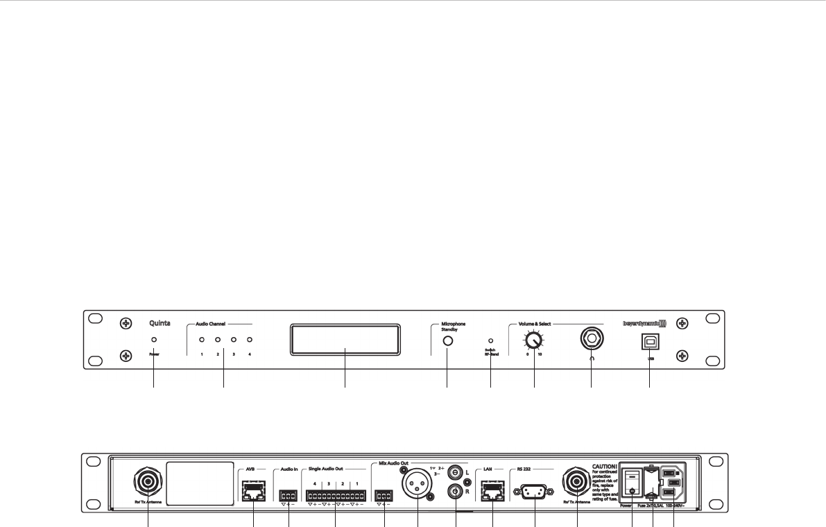
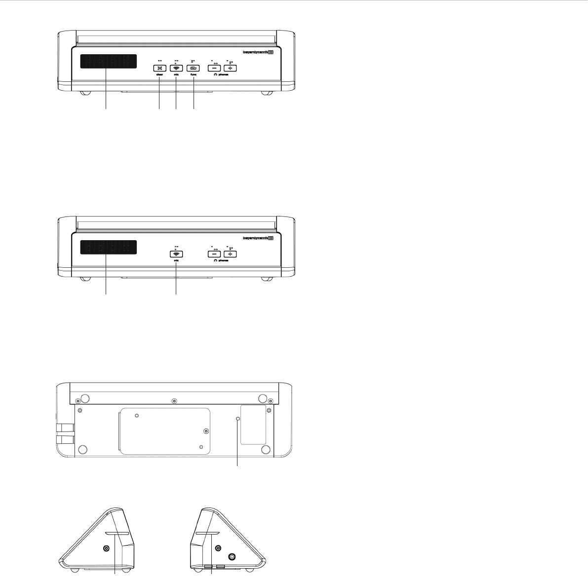
ᕡPower on LED
ᕢAudio channel LEDs 1 to 4 (white = channel vacant;
red = channel occupied)
ᕣDisplay to indicate operating mode, channel, headphone volume
ᕤStandby button to turn off all microphone units centrally
ᕥPush-button for frequency band selection
ᕦVolume control for headphone / channel (The headphone volume
is set by turning the control.
By pressing and turning you can select and listen to the
individual channels or a mix.
When pressing more than 3 seconds you will access the main
menu of the control unit.)
ᕧHeadphone connection
ᕨUSB connection
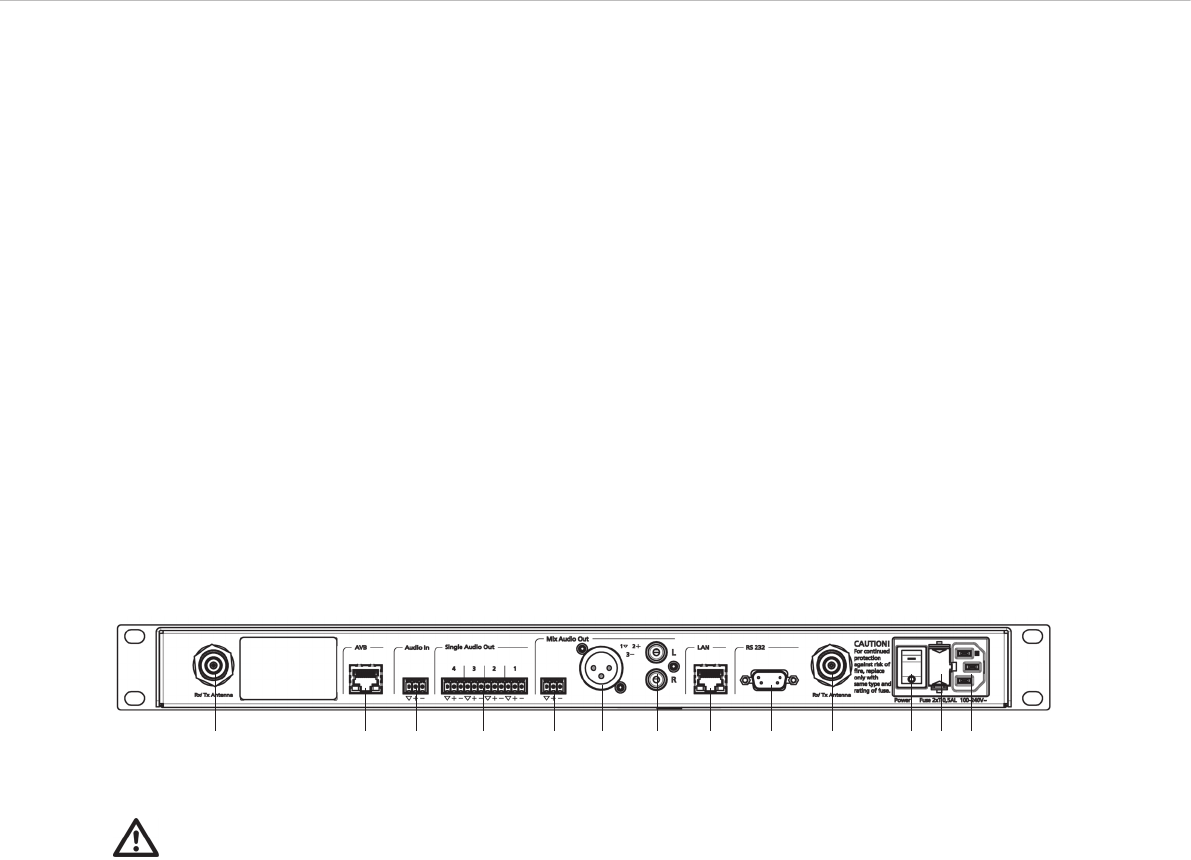
ᕩAntenna connections
µAVB (Audio Video Bridging) network connection for digital audio
signals via CAT5 cables, RJ45
¸Audio input (Audio IN) for the connection of external sound
sources, 3-pin Phoenix terminal strip, balanced
¹Audio output, individual channels, 4 x 3-pin Phoenix terminal
strips, balanced
ƸAudio output Mix (Master), 3-pin Phoenix terminal strips,
balanced
ƹAudio output Mix (Master), 3-pin XLR, balanced
ƺAudio output Mix (Master), RCA, unbalanced
ƻLAN connection for PC / network, RJ 45
ƼConnection for media control system / PC / network, RS 232
ƽOn/Off switch
ƾFuse
ƿMains connection
Quinta – Control Unit 7
Front
Rear
ᕡ
ᕩ µ ¸ ¹ Ƹ ƹ ƺ ƻ Ƽ ᕩ ƽ ƾ ƿ
ᕢ ᕣ ᕤ ᕥ ᕦ ᕧ ᕨ
2. Quinta CU Control Unit
The Quinta CU control unit is the heart of the system. It controls the
delegate and chairman microphone units. With one control unit a
maximum of 4 speakers (e.g. 3 delegates and 1 chairman) can speak
simultaneously. The radio transmission is in the triple band (2.4 /
5.2 / 5.8 GHz frequency band).
The control unit has been designed for installations on tables or 19"
rack mounting. When setting up the system, please follow the safety
instructions mentioned in chapter 1.
Furthermore, please note
• the ambient temperature of the installation site must not exceed
35 °C [95 °F].
• there must not be exceeding dust and humidity a the installation
site.
• that the unit is not exposed to direct sunlight.
• the connection must be protected against direct access during
operation.
• that there must be a strain relief of the cables.
• the installation site must be protected against vibrations.
2.1 Controls and Indicators
Quinta – Control Unit 8
ᕩ µ ¸ ¹ Ƹ ƹ ƺ ƻ Ƽ ᕩ ƽ ƾ ƿ
2.3 How to Connect the Antennae
2.3.1 Direct Connection
• Connect the antennae to the antenna connections ᕩ. Please
note that for diversity operation both antennae have to be
connected! A weighting circuit is used to make sure that the
better antenna signal is received.
• For stand-alone operation we recommend using the supplied
CA Q 11 angled rod antennae.
2.3.2 Remote Connection
• The Quinta CU control unit can also be operated with remote
antennae. We recommed extremely low attenuation connecting
cables which are 10 m [32.8 ft] or 20 m [65.6 ft] long. Please
note that the antennae have to be installed remotely.
2.2 Where to Place the Control Unit
• If you do not use remote antennae, place the Quinta CU control
unit in the room where the meeting takes place. If you use
remote antennae, place the antennae in the conference room.
• Avoid shadowing effect of the antennae, especially by metallic
surfaces.
• A free line of sight between the Quinta MU microphone units and
the antennae of the Quinta CU control unit is essential for the
operation of the microphone units. Big obstacles in between can
possibly affect the radio transmission. In such specific
installations the use of remote antennae can possibly achieve
an improvement of the RF situation.
• If you want to install several Quint CU control units in a 19"
rack, please make sure that there is a minimum distance of 1 U
between the control units to avoid interferences, especially if
you do not use remote antennae.
Important:
• There must be an unobstructed path between the micro-
phone units and the antennae, i.e. between the Quinta CU
control unit or the remote antennae and the microphone
units there must not be any obstacles. With a free line of
sight between the control unit and the microphone units
and the rod antennae the range is between 30 to 50 m
[98.4 ft to 164 ft].
For optimum range the surface of the table is important, wood or
plastic tables are ideal, but metal tables can cause interferences
and reduce the range.
• Please make sure that with a free line of sight the minimum
distance between the antennae and the microphone units is not
less than 1 m [3.2 ft].
Quinta – Control Unit 9
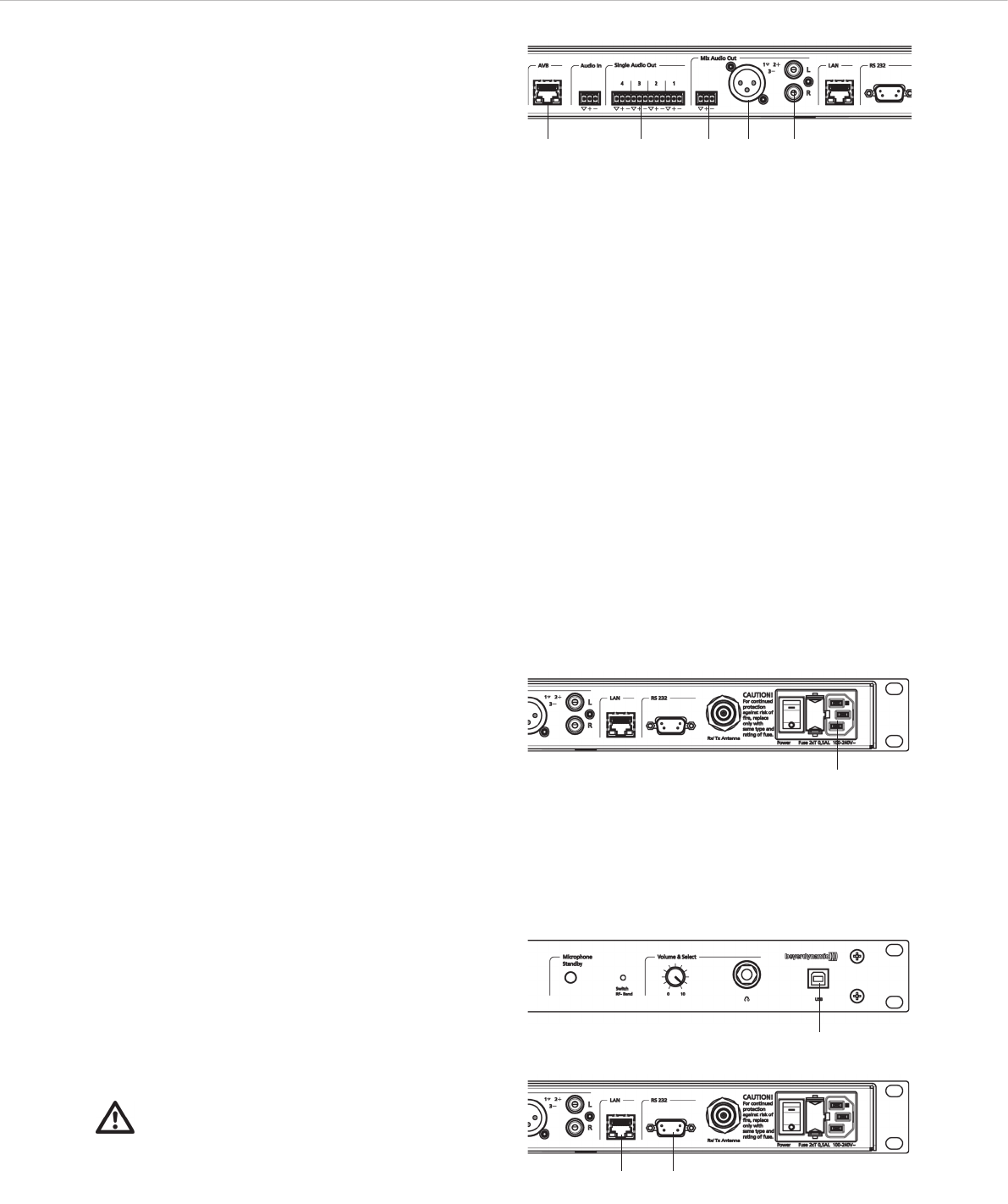
2.4 Audio Connection
• If required, connect the Audio Mix Ƹ, XLR ƹor Cinch ƺ
master output of the Quinta CU control unit to the input of a
mixing console or amplifier.
• If you want to feed the audio signals into a network, connect the
AVB connection * µto the network by using a CAT5 cable. You
can also connect other audio sources or devices with AVB
connection, which are defined as “Talker” (e.g. microphone) or
“Listener” (e.g. loudspeaker), as well as DSP devices for audio
data processing.
• You can connect e.g. external loudspeakers to the individual
channels of the audio output ¹.
• Always route cables running to the unit where they will not be
pinched or cut by heavy or sharp objects.
*AVB is a uniform standard for Audio/Video networks for data
communication with which the most different components can
communicate with each other.
AVB is based on IEEE 802 Ethernet for the real-time streaming of
audio and video contents via Ethernet.
AVB features a bandwidth reservation, a low jitter master clock, low
latencies and a timing mechanism for the synchronisation. AVB
supplies a sufficient raw data bandwidth to transmit up to 200 audio
channels via one single Gigabit Ethernet port. Field tests showed
that a part of this can be used for extended functions. In order to
achieve this, an AVB network separates the AVB data traffic from the
Standard Ethernet data traffic and manages streams accordingly.
This means that an AVB network can be connected to a Standard
Ethernet network to transfer data to and from the network. The
performance of the streaming of media can only be guaranteed
within a group of AVB capable devices.
µ ¹ Ƹ ƹ ƺ
2.5 Power Supply
• Verify that the voltage rating of the unit matches that of the AC
mains outlet you are to use. If you connect the unit to the wrong
voltage, you may seriously damage it.
• Always route cables running to the unit where they will not be
pinched or cut by heavy or sharp objects.
• Connect the Quinta CU control unit to the mains ƿ. The
internal power supply unit of the control unit can automatically
adjust between 100 and 240 V at 50 - 60 Hz.
ƿ
2.6 Connection of Media Control System and PC
• If you want to configure, control and monitor the system via
the Quinta Conference software, connect the USB connection
ᕨ or the LAN connection ƻ or RS 232 Ƽ (null modem cable
required) with a media control system or PC. The default IP
address of the Quinta CU control unit is: 192.168.1.55
• If the Quinta CU control unit is connected e.g. via a network
with a WLAN Access Point, you can access the web server of
the Quinta CU control unit e.g. with a smartphone.
ᕨ
Important:
Never access the Quinta CU control unit via the media
control system and the Quinta Conference software
simultaneously. In this case a correct function of the
system cannot be guaranteed. ƻ Ƽ
Quinta – Control Unit 10
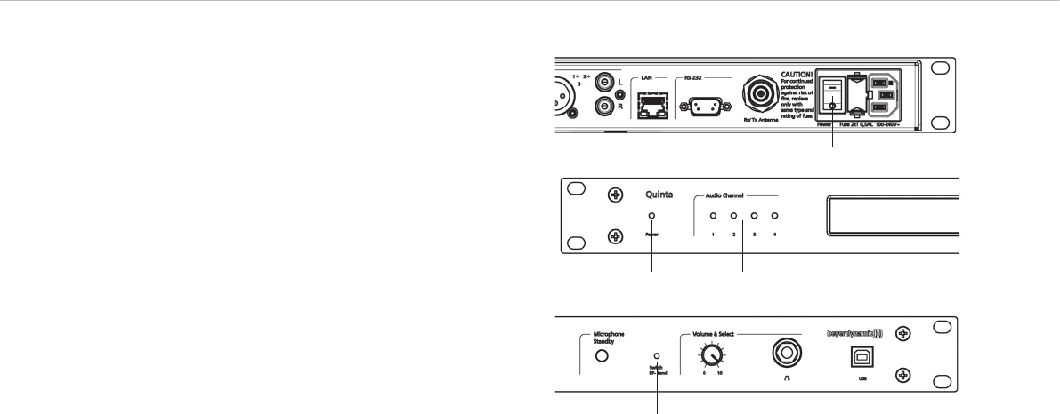
ƽ
2.7 How to Switch the Control Unit On/Off
• Turn on the Quinta CU control unit with the On/Off switch ƽ.
The Power on LED ᕡwill illuminate.
• The channel LED 1 to 4 will illuminate white to indicate the
availability. As soon as a microphone is activated, the channel
LED ᕢwill illuminate red to indicate that the channel is
occupied.
ᕡ ᕢ
• At the factory the RF bands 2.4; 5.2 or 5.8 GHz* will be
activated (Automatic Mode). This means that the Quinta CU
control unit will select a free frequency and if necessary it will
select a different free frequency without any interferences. This
operating mode is recommended for normal use. The free
frequencies for the Quinta CU control unit can be deactivated
via the Quinta Conference software. The microphone unit will
automatically be adjusted to the frequency of the Quinta CU
control unit.
• If required you can select a fixed frequency (Manual Mode).
Use the tip of a pencil or a paper clip to press the countersunk
push-button for RF band selection ᕥ. The push-button ᕥ
switches through all available frequencies one after another and
back to the “Automatic Mode”. The manual frequency selection
can take up to 1.5 seconds and is immediately displayed. The
microphone units are automatically adjusted to the selected
frequeny band.
*Note:
The availability of the RF bands 2.4; 5.2 or 5.8 GHz depends
on the selected region.
ᕥ
2.8 Rack Mounting
• When mounting the Quinta CU control unit into a 19" rack
housing leave 1 U for a ventilation panel above and below the
control unit.
• Make sure that the mains connection, mains switch and all
audio connections on the rear of the device are easily
accessible.
Quinta – Control Unit 11
2.9 Main Menu
Press the volume control ᕦ approx. 3 seconds until the Quinta CU
control unit displays “Main Menu”.
By turning and pressing you can display and set different parameters
in the main menu.
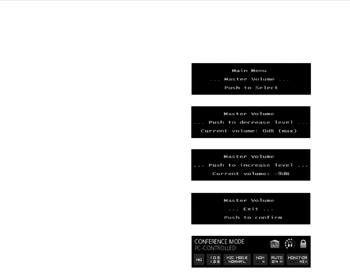
2.9.1 Master Volume
• Press the volume control ᕦ approx. 3 seconds until the Quinta
CU control unit displays “Main Menu”.
• Turn the volume control ᕦ to the right or left until “Master
Volume” is displayed.
• Press the volume control ᕦ to enter the submenu “Push to
decrease level”.
• Press the volume control ᕦ, if you want to reduce the volume.
• If you want to increase the system volume, turn the volume
control ᕦ clockwise to enter the submenu “Push to increase
level”.
• Press the volume control ᕦ to increase the volume. The maximum
setting is 0 dB.
• After setting the parameter, turn the volume control ᕦ clockwise
until the submenu “Master Volume” - “Exit” ist displayed.
Press the volume control ᕦ to leave the menu item “Master
Volume”.
• The default screen is displayed.
Quinta – Control Unit 12
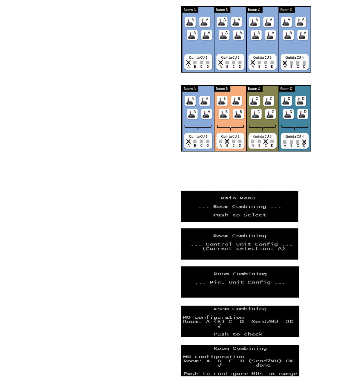
2.9.2 Room Combining
The “Room Combining” function is used when you want to operate
or combine several Quinta systems in different rooms (A, B, C, D).
All microphone units and control units have been set to “A” at the
factory. Refer to picture “Factory setting of control units and micro-
phone units”. When you want to operate several systems in different
rooms at the same time, you have to re-configure the systems;
otherwise interference will occur. You can configure the systems for
a maximum of four rooms.
When using the “Room Combining” function for the first time, please
proceed as described in the following:
• Place the Quinta CU control units and the Quinta MU microphone
units in the rooms A, B, C, D.
Room A
• As the control unit and the microphone units are configured to
“A” there are no changes necessary for the control unit and
microphone units in room A.
Room B to D
• The control unit and microphone units in the rooms B, C, D must
be configured. The configuration of the control unit and the
microphone units in room B is described in the following.
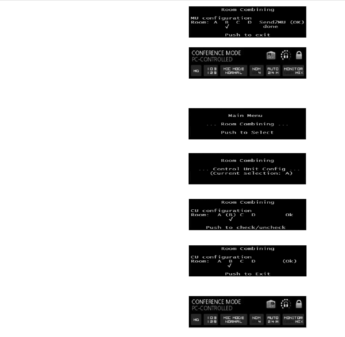
• Switch on the microphone units in room B only.
• Configure the microphone units in room B. Press the volume
control ᕦ approx. 3 seconds until the Quinta CU control unit
displays the main menu.
• Turn the volume control ᕦ to the right or left until “Room
Combining” is displayed.
• Press the volume control ᕦ to enter the submenu.
• Turn the volume control ᕦ until “Mic. Unit Configuration” is
displayed.
• Press the volume control ᕦ to enter the submenu “MU
Configuration”. For the microphone units in room B turn the
volume control ᕦ until “(B)” is displayed and press the volume
control to select “(B)” (it is ticked).
• In order to transmit the configuration for room B to the micro-
phone units in room B, turn the volume control ᕦ until
“(Send2MU)” is displayed and press the volume control ᕦ. Below
“(Send2MU)” the note “done” is displayed to show that the
configuration has been transmitted to all microphone units in room
B having a radio link to the control unit.
Factory setting of control units and microphone units
Configuration of control units and microphone units in four
different rooms
Quinta – Control Unit 13
• In order to confirm with “OK” turn the volume control ᕦ clockwise
until “(OK)” is displayed. Press the volume control to confirm and
leave the menu.
• The default screen still displays “A”.
• As the control unit is still set to “A” (factory setting), the micro-
phone units will lose the radio link to the control unit. The
microphone button of the microphone units will flash red.
• In order to configure the control unit to “B” press the volume
control ᕦ approx. 3 seconds until the Quinta CU control unit
displays the main menu.
• Turn the volume control ᕦ to the right or left until “Room
Combining” is displayed.
• Press the volume control ᕦ to enter the submenu.
• Press the volume control ᕦ once again to enter the submenu for
configuration of the control unit. For the control unit in room B
turn the volume control until “(B)” is displayed and press the
volume control to select “B” (it is ticked).
• In order to confirm with “OK” turn the volume control ᕦ clockwise
until “(OK)” is displayed. Press the volume control to confirm and
leave the menu.
• The default screen displays “B”.
• The microphone units will link to the control unit again. The
microphone button will illuminate white.
• Switch off the microphone units and control unit in room B.
• Continue with the configuration of the control units in room C and
D as described for room B.
• Should you use the “Room Combining” function again, you do not
need to set anything in the “MU Configuration” menu, but only in
the “CU configuration” menu. Here you select the rooms you want
to combine. The microphone units with the selected room
designation will link to the control unit.
Quinta – Control Unit 14
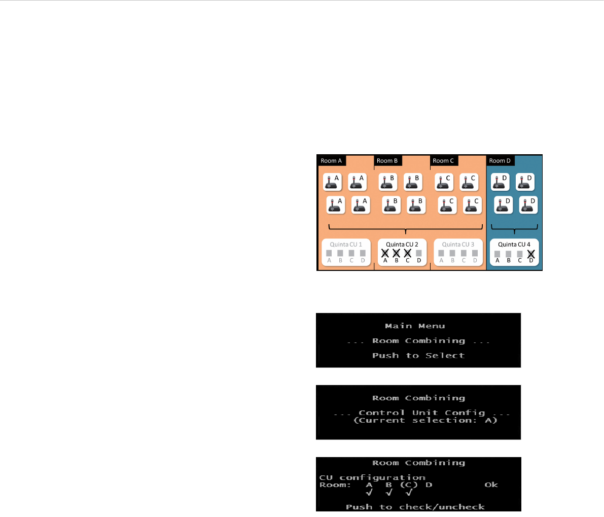
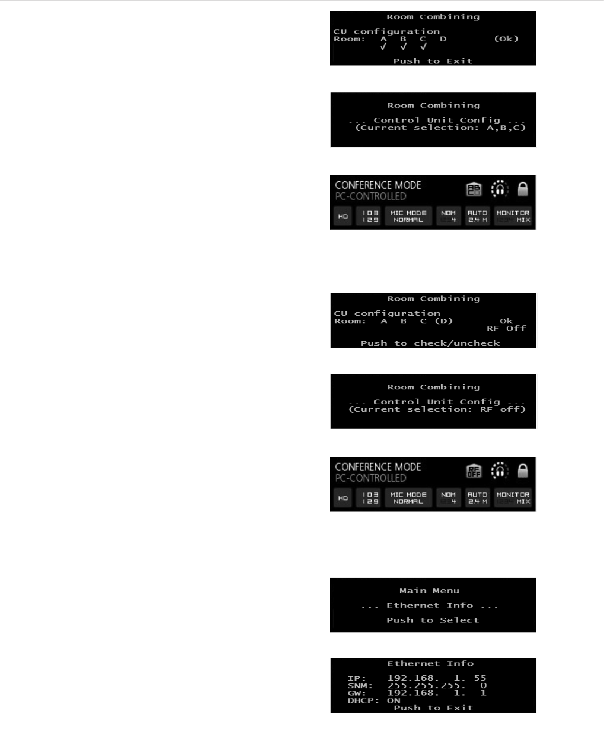
How to combine different rooms – example
• In our example the rooms A, B, C are combined.
In room D a separate system with control unit and microphone
units will be operated.
• In order to avoid interference between the systems, you must turn
off the control units in room A and C or deactive the radio
module of the control unit via the menu of the control unit or with
the Quinta Conference Software via PC by removing all ticks under
the “Room Combining” - “CU configuration” menu item.
• The microphone units which are configured for room A, B, C will
now link to the control unit in room B.
• Press the volume control ᕦ approx. 3 seconds until the
Quinta CU control unit displays “Main Menu”.
• Turn the volume control ᕦ to the right or left until “Room
Combining” is displayed.
• Press the volume control ᕦ to enter the submenu.
• Press the volume control ᕦ once again to enter the submen for the
configuration of the Quinta CU control unit. Turn the volume
control ᕦ until “(A)” is displayed and press the volume control ᕦ
to select “(A)” (a tick is displayed under the “A”). Turn the
volume control ᕦ until “(B)” is displayed and press the volume
control ᕦ to select “(B)” (a tick is displayed under the “B”). Turn
the volume control ᕦ until “(C)” is displayed and press the
volume control ᕦ to select “(C)” (a tick is displayed under the
“C”).
• Do not activate room D, as this is a separate system in a separate
room.
• In room A and C you must turn off the control units or deactive the
radio module of the control unit via the menu of the control unit
or with the Quinta Conference Software via PC by removing all
ticks under the “Room Combining” - “CU configuration” menu
item.
• The microphone units which are configured for room A, B, C will
now link to the control unit in room B.
Configuration of control units and microphone units in the
combined rooms A, B, C and in room D
•Important:
–The microphone units in the respective rooms must have a
radio link to the control unit.
– The configuration for room A, B, C or D is stored in the
appropriate microphone units.
– When you have only one Quinta system which you want to
use in one room only, you can keep the factory setting of “A”.
Quinta – Control Unit 15
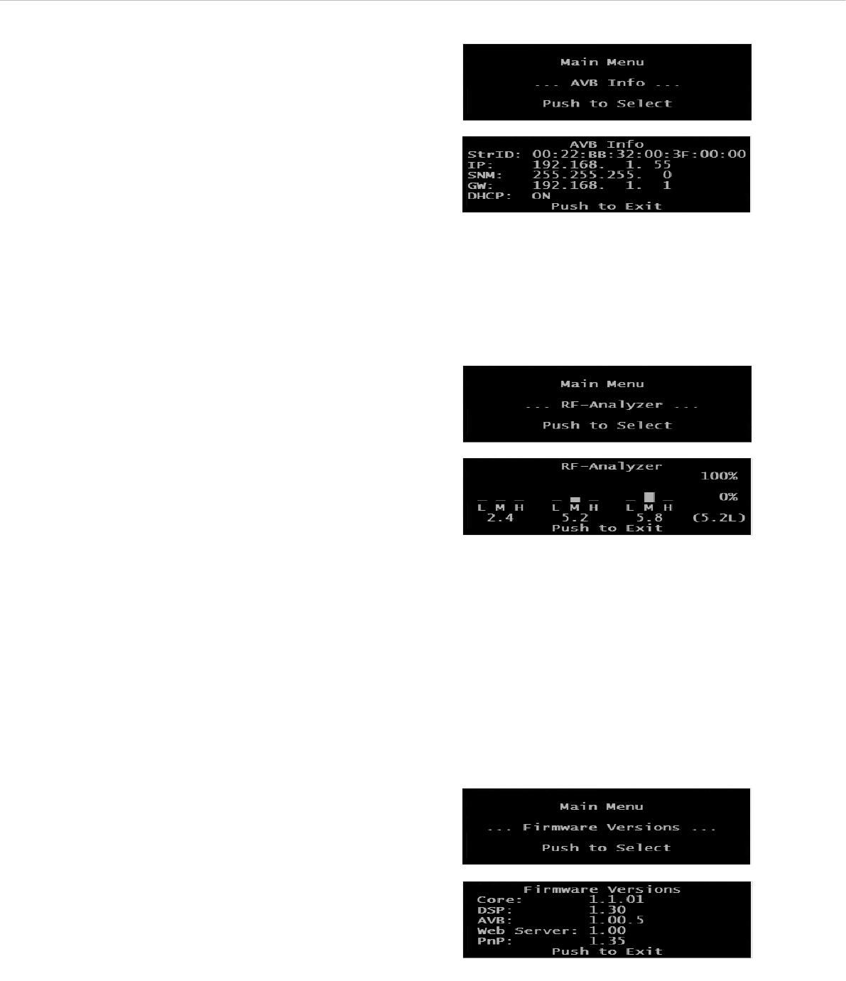
How to deactivate the radio module of the control unit
• If the radio module of the control unit is to be deactivated so
that there is no radio link between microphone units and control
unit, remove all ticks in the menu “Room Combining - CU Con-
figuration”.
• When you enter the “Room Combining” menu item, the line
“Current selection: RF off” is displayed.
• The default screen also displays “RF off”.
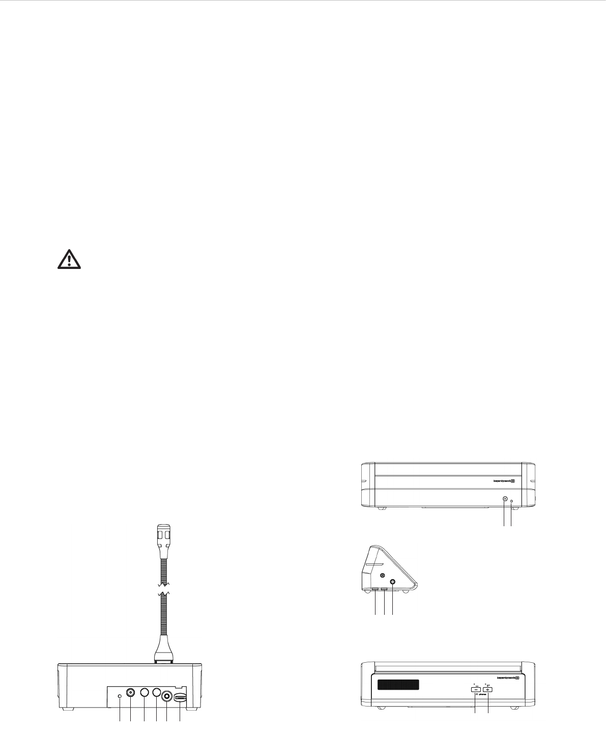
2.9.3 Ethernet Info
• Press the volume control ᕦ approx. 3 seconds until the
Quinta CU control unit displays “Main Menu”.
• Turn the volume control ᕦ to the right or left until “Ethernet Info”
is displayed.
• Press the volume control ᕦ to enter the submenu.
• In the display you can now read all information of the Ethernet
connection.
• Press the volume control ᕦ to leave the menu.
• The default screen is displayed.
• In order to confirm with “OK” turn the volume control ᕦ clockwise
until “(OK)” is displayed. Press the volume control ᕦ to
confirm and leave the menu.
• The default screen is displayed.
• When you now enter the “Room Combining” menu item, the line
“Current selection: A, B, C” is displayed.
• The default screen also displays A, B, C.
Quinta – Control Unit 16
2.9.5 RF-Analyzer
• Press the volume control ᕦ approx. 3 seconds until the Quinta CU
control unit displays “Main Menu”.
• Turn the volume control ᕦ to the right or left until “RF-Analyzer”
is displayed.
• Press the volume control ᕦ to enter the submenu.
• The “RF Anlayzer” displays how much the frequency range is
already used by other devices that use the same frequencies
(e.g. other Quinta systems, WiFi, etc.) With “RF-Analyzer” you
can find out which frequency band is most suitable.
• To interpret the displayed values correctly, a detailed knowledge
about other wireless technologies is required. A WiFi network,
for example, is only displayed with higher values when data
traffic is actually used. It is not displayed of which type of
wireless technology the devices are that show values. The bars
are an indicator that indicate the current wireless energy / time
on the specific frequencies.
• Press the volume control ᕦ to leave the menu.
• The default screen is displayed.
2.9.6 Firmware Versions
• Press the volume control ᕦ approx. 3 seconds until the Quinta CU
control unit displays “Main Menu”.
• Turn the volume control ᕦ to the right or left until “Firmware
Versions” is displayed.
• Press the volume control ᕦ to enter the submenu.
• The firmware versions of Core, DSP, AVB, Web Server and PnP
are displayed.
• Press the volume control ᕦ to leave the menu.
• The default screen is displayed.
2.9.4 AVB Info
• Press the volume control ᕦ approx. 3 seconds until the Quinta CU
control unit displays “Main Menu”.
• Turn the volume control ᕦ to the right or left until “AVB Info” is
displayed.
• Press the volume control ᕦ to enter the submenu.
• In the display you can now read all information of the AVB
connection.
• Press the volume control ᕦ to leave the menu.
• The default screen is displayed.
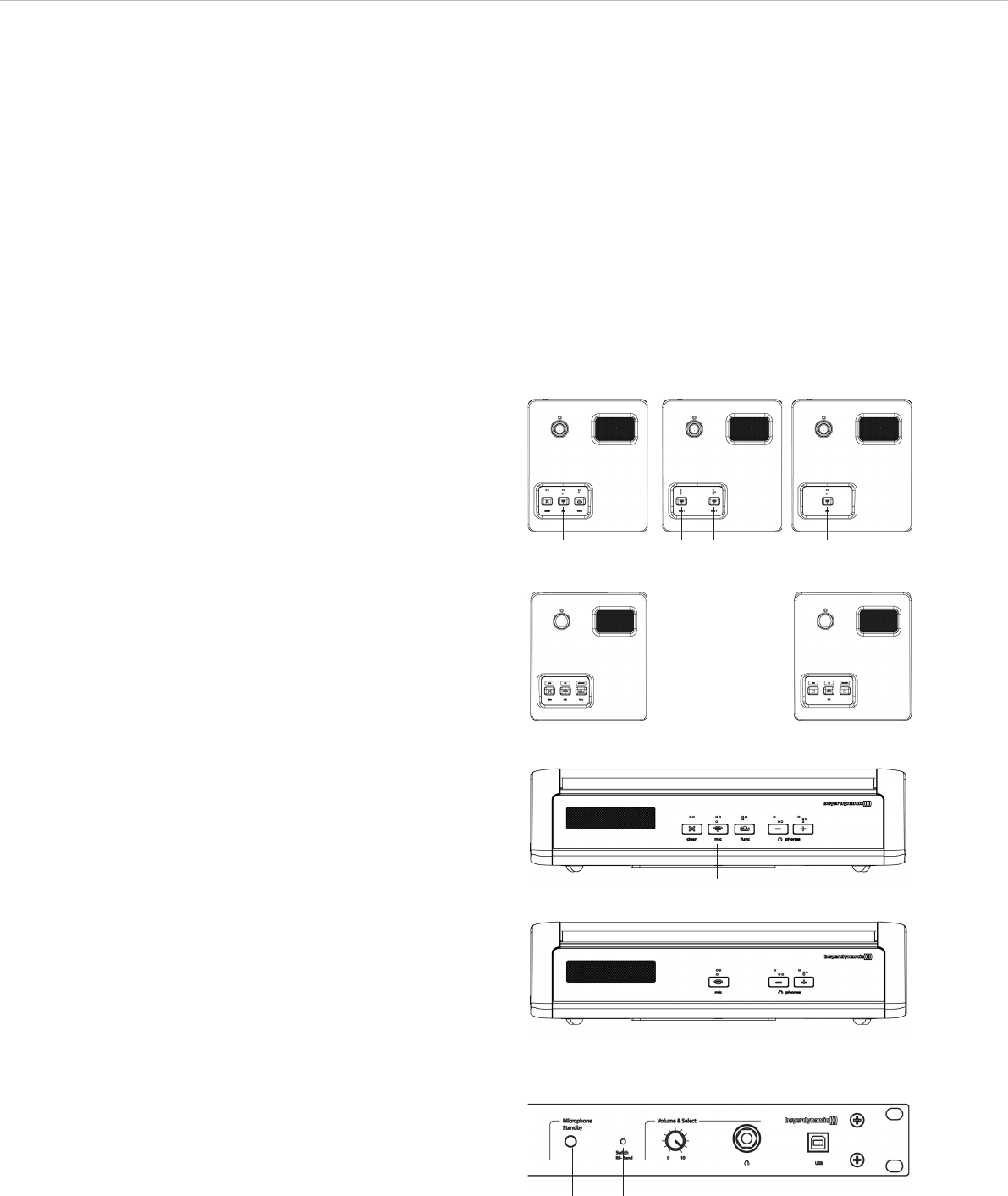
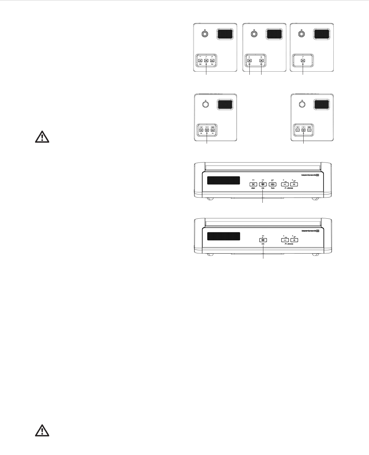
Quinta – Microphone Units 17
3. Quinta MU Microphone Units
For the Quinta conference system there are different microphone
units available:
• Quinta MU 23 chairman microphone unit with three buttons
(microphone, clear, function)
• Quinta MU 22 double delegate microphone unit with two
microphone buttons
• Quinta MU 21 delegate microphone unit with one microphone
button
• Quinta MU 33 chairman microphone unit with Revoluto
technology, three buttons (microphone, clear, function) and
two buttons for volume control of the headphone output
• Quinta MU 31 delegate microphone unit with Revoluto
technology, one microphone button and two buttons for volume
control of the headphone output
The Quinta MU 21/22/23 microphone units are provided with a
locking XLR connection for removable gooseneck microphones of the
Classis GM 31x Q series, 3-colour backlit buttons, braille above the
buttons, an integrated wideband loudspeaker with equalization and
a headphone output with volume control.
The Quinta MU 31/33 microphone units are provided with the
Revoluto technology for maximum freedom of movement and 3-colour
backlit buttons, braille above the buttons, an integrated two-way
loudspeaker with equalization and two buttons for volume control of
the headphone output.
• Each microphone unit is programmed at the factory with an
individual worldwide unique device ID so that the Quinta CU
control unit can control the microphone units.
• Each microphone unit is addressed with this individual device ID
in the transmission protocol via radio transmission.
Important:
• The charging contacts of the microphone units can
cause damages, injures or fire damages if they come
into contact with conductive materials such as
jewellery, keys or chains. This can lead to a closed
circuit and heat up the material.
• If the microphone units are to be operated by an external power
supply, you can use the CA 2459 mains charger adapter.
•To align the gooseneck microphone of the Quinta MU 21/22/23
microphone units and to avoid twisting it too far and causing
premature wear, the gooseneck must not be bent further than an
angle of 90° at maximum.
ቢ ባ ቤ ቤ ብ ቦ
3.1 Controls and Indicators
ቢPower on and operating control LED
ባDC socket for charging the rechargeable batteries of the microphone
unit or for DC operation
ቤCharging contacts for charging in the CD 2 charger
(Quinta MU 23/22/21) or CD3 (Quinta MU 33/31)
ብHeadphone connection
ቦVolume control for headphone connection
Quinta MU 23/22/21
Rear View
Quinta MU 33/31
Rear View
Lateral View
Front View
ቢባ
ቤ ቤ ብ
ቦ ቦ
Quinta – Microphone Units 18
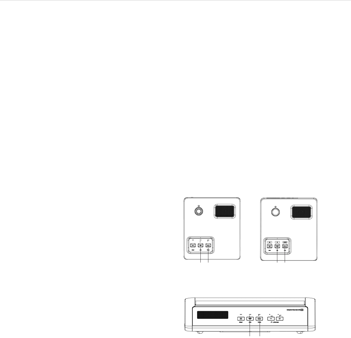
Quinta MU 23 Chairman Microphone Unit
Quinta MU 22 Double Delegate Microphone Unit
Quinta MU 21 Delegate Microphone Unit
ቧ
ቨ
ቩ
ቫቭቪ
ቧ
ቨ
ቩ
ቫ
ቧ
ቨ
ቩ
ቫ
Bottom of Microphone Unit Quinta MU 23/22/21
ቮ
ቫ
Quinta MU 23 V Chairman Microphone Unit
Quinta MU 21 V Delegate Microphone Unit
ቧ
ቨ
ቩ
ቫቭቪ
ቧ
ቨ
ቩ
ቫቱተ
ቧOpening for unlocking the gooseneck microphone
ቨConnection for gooseneck microphone
ቩLoudspeaker
ቪ“Clear” button to clear all delegate microphone units /
Attention: Only with Quinta MU 23 V this button acts also as
“yes” voting button
ቫMicrophone button / Attention: Only with Quinta MU 23 V /
MU 21 V this button acts also as “no” voting button
ቭProgrammable function button / Attention: Only with
Quinta MU 23 V this button acts also as “abstain” voting
button
ቮReset button to restart the integrated microcontroller (refer
also the item “Microphone unit cannot be switched off” in
chapter 7. “Trouble Shooting”)
ተ“yes” voting button with Quinta MU 21 V
ቱ“abstain” voting button with Quinta MU 21 V
Quinta – Microphone Units 19
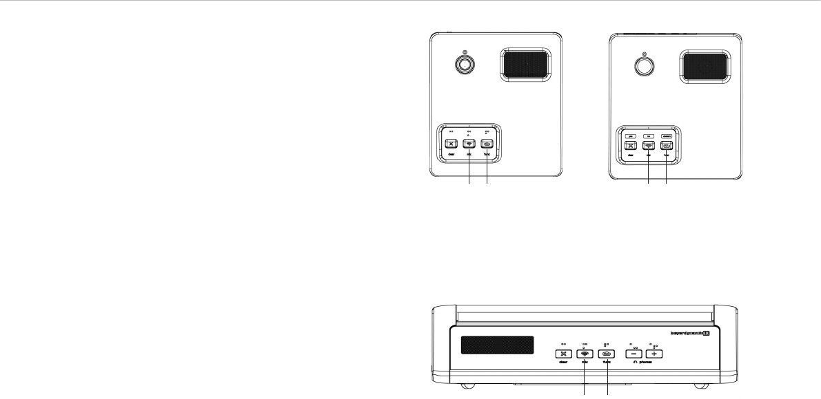
ቩLoudspeaker
ቪ“Clear” button to clear all delegate microphone units
ቫMicrophone button
ቭProgrammable function button
ቮReset button to restart the integrated microcontroller (refer
also the item “Microphone unit cannot be switched off” in
chapter 7. “Trouble Shooting”)
ቯLED strips
Quinta MU 33 Chairman Microphone Unit
Quinta MU 31 Delegate Microphone Unit
Bottom of Microphone Unit Quinta MU 33/31
ቪ ቫ ቭቩ
ቫ
ቮ
ቩ
Lateral View
ቯ ቯ
Quinta – Microphone Units 20
3.2 How to Connect the Gooseneck Microphone
to Quinta MU 21/22/23
The following gooseneck microphones with an LED are available to
connect to the microphone unit.
– Classis GM 313 Q; 300 mm [11.81"] in length
– Classis GM 314 Q; 400 mm [15.75"] in length
– Classis GM 315 Q; 500 mm [19.69"] in length
– Classis GM 316 Q; 600 mm [23.62"] in length
• Take the gooseneck microphone by the shaft, put it into the
connection for gooseneck microphones ቨand press the shaft
downwards until it locks in place.
• If you want to remove the gooseneck microphone, press into
the opening for unlocking the gooseneck microphone ቧwith
the supplied tool or a similar thin tool. Remove the gooseneck
microphone by taking it by the shaft and pulling.
3.3 Switching On / Off
How to switch on and allocate the microphone units
• The microphone unit is switched on by pressing the micro-
phone button. The microphone button ቫ will light up for a
moment and the operating control LED ቢ on the rear will
illuminate green. When the connection to the Quinta CU
control unit has been established, the buttons of the micro-
phone unit will illuminate white.
• To activate the microphone or to allocate the microphone unit
to a free channel of the Quinta CU control unit, press the
microphone button ቫ once again. Depending on the operating
mode, the microphone button will illuminate green (normal
operating mode) or red (request-to-speak mode).
Switching off
• By pressing the microphone button ቫ for more than 2 seconds
the microphone unit is switched off.
• If you press the standby button ᕤ of the Quinta CU control
unit for more than 3 seconds, you switch off all the active
Quinta MU microphone units within the range of the Quinta
CU control unit.
• Furthermore, the microphone units are switched off
automatically, when they do not receive a signal from the
Quinta CU control unit for more than 3 minutes. ᕤ ᕥ
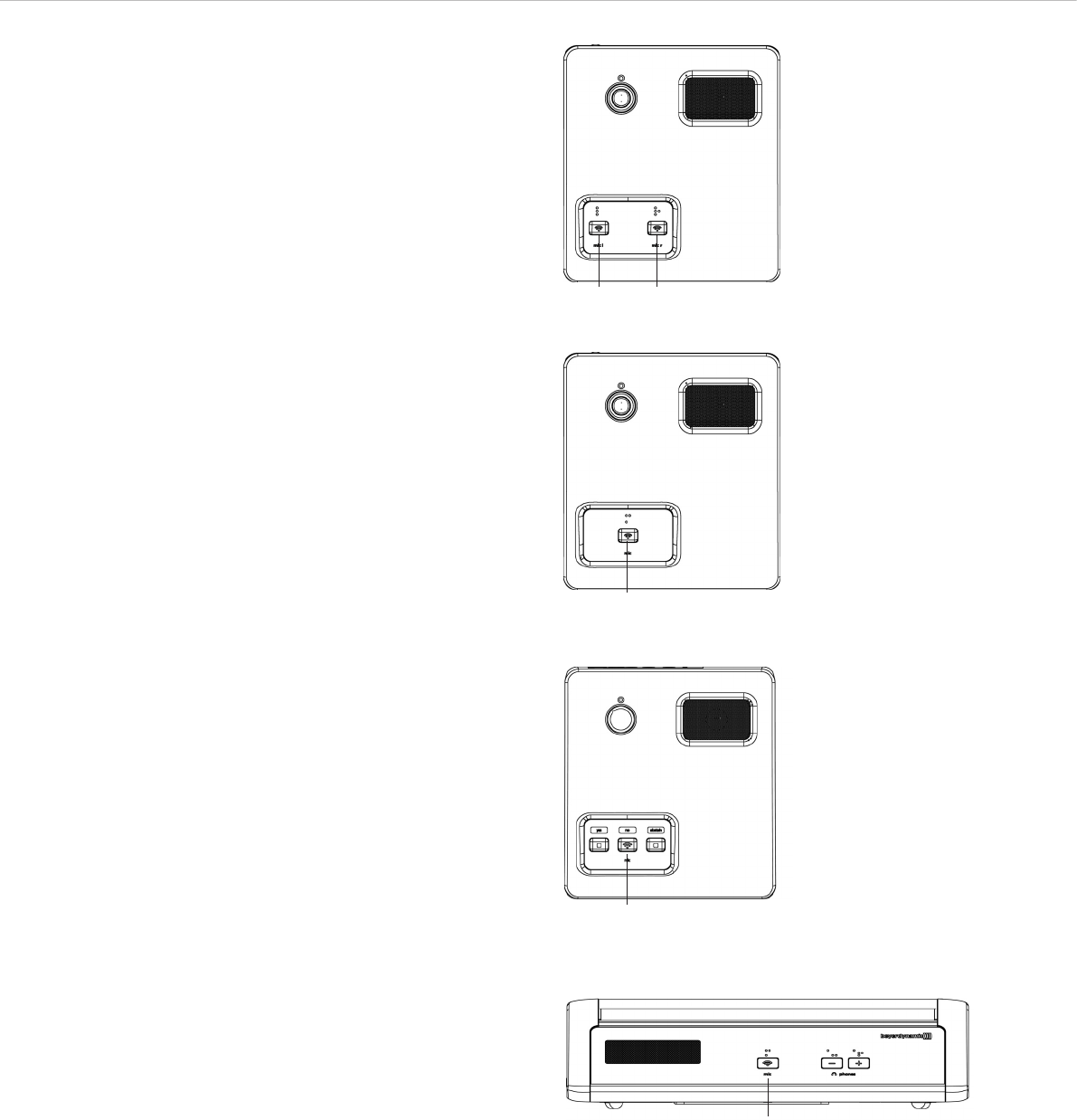
ቫ ቫ ቫ ቫ
Quinta MU 23 Quinta MU 21Quinta MU 22
Quinta MU 23 V Quinta MU 21 V
Quinta MU 33
ቫ
ቫ
Quinta MU 31
ቫ ቫ
Quinta – Microphone Units 21
Function Test
You can test if the microphone units are operating:
• Connect a headphone to the Quinta CU control unit ᕧ.
• Turn the control ᕦto set the volume and press the control ᕦ
several times until you have listened to all channels
(i.e. 4 channels).
ᕦ ᕧ
Important:
• With the Quinta Conference software you can
deactivate the manual switching off of the microphone
unit.
• If the microphone unit is out of range of the control
unit or does not have the correct PIN code, the micro-
phone button ቫ will flash red. After approx. 3 minutes
the microphone unit will switch off automatically.
• Should the system fail to operate, i.e. the microphone
unit is switched on, but no sound is heard, check the
audio settings with the Quinta Conference software. If
RF problems occur the microphone button ቫ will flash
red. Should the system still fail to operate, please
contact your beyerdynamic representative.
3.5 Powering with CA 2459 Mains Power Adapter
• The Quinta MU microphone units can also be powered via the
external CA 2459 mains charger adapter, which is connected
to the DC socket ባ on the rear of the microphone unit.
• While the CA 2459 mains charger adapter is connected, the
rechargeable battery of the microphone unit is charged. Refer
also to chapter 6. “Battery Charging with External Mains
Power Adapter”.
3.4 Powering / Operating Time
• The microphone units have an integrated rechargeable battery
allowing a minimum operating time of 20 hours when fully
charged.
• When the battery charge is too low for a satisfactory operation,
the operating control LED ቢ on the rear of the microphone
unit will flash. The remaining time of operation will be around
60 minutes.
• The charging state of the microphone units can be displayed
with the Quinta Conference software on a PC connected to the
Quinta CU control unit or via the integrated web server.
Furthermore, it can be displayed on an external media control
system connected to the Quinta CU control unit.
ቢ ባ
Quinta MU 33/31 – Rear View
Quinta MU 23/22/21
Rear View
ቢባ
Quinta – Microphone Units 22
3.6.1 Normal Operating Mode
• Press the microphone button ቫto switch on the microphone.
• The red LED of the gooseneck microphone will illuminate and
the microphone button ቫwill illuminate green: The micro-
phone is ready to speak into it.
• Using the Quinta CU control unit, up to 4 participants
(e.g. 3 delegates and 1 chairman) can speak simultaneously
depending on the setting.
3.6.2 FiFo Mode
• If the microphone units operate in the FiFo mode (first in - first
out), the microphone unit that was switched on first, will be
switched off, when another microphone unit is switched on and
the number of open microphones (NOM) will be exceeded.
3.6.3 Push-To-Talk Mode
• If the microphone units operate in the Push-To-Talk mode
(PTT), the microphone button must be pressed as long as
someone speaks into the microphone. This configuration is
recommended for short interruptions during the meeting.
3.6 Operating Modes
The different operating modes such as “Normal”, “Push-To-Talk”
or “Voice Activation” are adjusted with the Quinta Conference soft-
ware for all microphone units. The standard operating mode is
“Normal”. Please refer also to the appropriate “Quinta Conference
Software” or “Quinta Web Server”manual.
Important:
If the number of open microphones is exceeded, a
microphone can only be switched on manually when
another microphone unit has been switched off.
3.6.4 Voice Activation Mode
• If the microphone units operate in the Voice Activation mode,
the microphone units are switched on via voice control. That
is the microphone unit is switched on as soon as someone
speaks into the microphone. In this case it is not necessary to
press the microphone button.
Important:
The threshold and the hold time can be configured with
the “Quinta Conference” software for all microphone
units.
Quinta MU 33
ቫ
ቫ
Quinta MU 31
ቫ ቫ ቫ ቫ
Quinta MU 23 Quinta MU 21Quinta MU 22
Quinta MU 23 V Quinta MU 21 V
ቫ ቫ
Quinta – Microphone Units 23
3.7 Maintenance of the Microphone Units
• For cleaning the Quinta MU microphone units when they are
slightly dirty (finger prints, dust, jam or juice) use a soft, damp
cloth, sponge or brush and mild liquid cleaning agent
(e.g. washing-up liquid). Do not use any solvent containing
cleaners.
• Make sure not to allow any water to enter the microphone
capsule or housing.
• Clean the charging contacts with spirit or isopropyl alcohol from
time to time. While cleaning avoid contact with the painted
surface.
• Clean the pop shield of the gooseneck microphone for Quinta
MU 21/22/23 with clear, warm water. Make sure that it is
completely dry before you put it on the microphone again.
4. Programmable Functions of the Microphone Units
with the Quinta Conference Software
The functions of the microphone units described in the following
are only available, when they have been programmed with the
Quinta Conference software before. Please refer to the “Quinta
Conference Software” manual.
4.1 Security Code
By using the Quinta Conference software you can enter an
alphanumerical code for the Quinta MU microphone units and the
Quinta CU control unit within one system. This will increase the
safety against unauthorised listening. Microphone units, which do
not have this code are not recognised by the control unit and will be
deactivated.
Depending on the configuration the following functions are possible
with the function button ቭ: mute, clear or priority. The function
button can be configured via the control unit with the Quinta
Conference software.
1. Normal
All active delegate microphone units will be cleared and the
microphone of the chairman unit will be switched on. The
delegates can switch on their microphones again, when the
chairman switches off his microphone.
2. Mute
All active delegate microphone units will be muted when the
chairman is speaking and will be reactivated when the
chairman switches off his microphone.
3. Clear
All active delegate microphone units are cleared an can be
switched on afterwards.
4. How to Mute Audio IN ports
First push mutes the port, the next one enables it, third one
mutes again etc.
If the chairman presses the function button, the audio input
of the Quinta CU control unit will be muted. The function
button ቭilluminates red.
4.2 Programmable Function Button of the Chairman Microphone Unit
Quinta MU 33
ቫ ቭ
Quinta MU 23 Quinta MU 23 V
ቫ ቭ ቫ ቭ
Quinta – Microphone Units 24
5. How to Mute Audio IN ports and clear all active delegate units
By pressing the function button a second time, mute is
released. By pressing the function button a third time, the
audio input is muted again and all active delegate units will be
cleared etc.
The function button ቭilluminates red.
6. How to Mute Audio OUT ports
First push mutes the port, the next one enables it, third one
mutes again etc.
If the chairman presses the function button of his/her micro-
phone unit, the audio output of the Quinta CU control unit will
be muted. The function button ቭilluminates red.
7. “RS 232 Message” Function
A command is sent via the RS 232 serial interface from the
Quinta CU control unit and a programmed function is carried
out via a media control system for instance (e.g. light control).
At the same time a command is also sent for other functions
via the RS 232 serial interface from the Quinta CU control
unit.
8. Command A/B
Two different commands according to the duration of the push
of the function button.
< 1 second = command “Short press string” is transmitted
> 1 second = command “Long press string” is transmitted
These commands can be set individually with the Quinta
Conference software.
Quinta MU 33
ቫ ቭ
Quinta MU 23 Quinta MU 23 V
ቫ ቭ ቫ ቭ
Quinta – Microphone Units 25
4.3 Request-to-Talk Mode
• This operating mode is only possible in conjunction with a PC
using the Quinta Conference software or a media control
system (AMX®, Crestron®, Cue etc.).
• The request-to-talk is registered in the system by pressing the
microphone button ቫof the microphone unit.
• The allocation is made by the operator at the PC or touch
screen of the media control system.
• The microphone button ቫ is illuminated red to indicate the
request-to-talk.
• If you press the microphone button ቫagain, the request-to-
talk is cleared. The backlit microphone button ቫ will
illuminate white.
Quinta MU 22 Double Delegate Microphone Unit
Quinta MU 21 Delegate Microphone Unit
Quinta MU 31 Delegate Microphone Unit
ቫ
ቫ
ቫ
ቫ
Quinta MU 21 V Delegate Microphone Unit
ቫ

Quinta – Charger 26
5.2 Notes for Microphone Units and Rechargeable
Batteries
• To achieve a 100% battery capacity of the rechargeable batteries,
all microphone units should have 2 complete charging cycles
(charging and discharging) at least. Only after several charging and
discharging cycles, the rechargeable batteries will achieve their
full capacity.
• The Quinta MU microphone units are provided with high-
performance nickel-metal hydrid (NiMH) batteries. These
guarantee operating times of approx. 20 hours. It takes about
2.5 hours to charge them.
• The service life of the batteries largely depends on the manner in
which they are looked after and on how well the user recharges
them. To extend the service life of the batteries for as long as
possible, the following charging cycle is recommended:
– Do not keep the microphone units in the charging case when
it is switched on.
– Only put the microphone units in the charging case before a
conference / application and fully charge them until the “fully
charged” status is shown.
– In particular, when the microphone units are inserted, the
charging case should not be constantly switched on and off.
For each charging cycle, there is an initial 5-minute charge to
check the battery status. If the case with the microphone units
is switched on every day (for example, because the mains is
switched off automatically or by a cleaner), the microphone
units will be slowly but constantly overcharged and this will
damage the batteries.
– The NiMH batteries used minimise the so-called “memory
effect”, but their capacity is reduced when they are only
partially discharged on a regular basis. For this reason, the
microphone units should be fully discharged every three
months until they switch off automatically. They can then be
fully recharged. This procedure can, if necessary, be repeated
a second time.
– If, despite this measure, the microphone unit does not operate
for a sufficiently long period of time, the battery has reached
the end of its service life and must be replaced. The typical
service life of the battery is greatly dependent on whether or
not the above points are observed. This is why batteries are
not covered by warranties. If the above points are observed, a
battery typically has a service life of at least two years or
500 complete charging cycles, depending on which occurs
first.
Note:
• If an error has occurred, try to restart the charging
process. If the LEDs are still flashing rapidly, please
contact your beyerdynamic dealer.
• For a reliable charging of the rechargeable batteries and
in order to avoid long-term damages the ambient
temperature must not exceed +35 °C [95 °F] during
charging.
5. Quinta CD 2 Charger in the
Quinta CC 2 | CC 2 / 600 Case and
Quinta CD 3 in the Quinta CC 3 Case
Quinta CC 2 is a modular charging and transport case for the Quinta
MU 23/22/21 microphone units. The basic version the Quinta CC 2
consists of a top cover (Quinta CT 2), a charger (Quinta CD 2) for 10
Quinta MU 23/22/21 microphone unit and a bottom with casters
(Quinta CW 2). This version is suitable for Quinta MU 23/22/21
microphone units using the Classis GM 313 Q, GM 314 Q and
GM 315 Q microphones.
For microphone units using the Classis GM 316 Q microphone the
version Quinta CC 2 / 600 with a higher top cover (Quinta CT 2 / 600)
will be available.
Quinta CC 3 is a modular charging and transport case for the
Quinta MU 33/31 microphone units. The basic version the Quinta CC3
consists of a top cover (Quinta CT 2), a charger (Quinta CD 3) for 12
Quinta MU 33/31 microphone unit and a bottom with casters
(Quinta CW 2).
• With the Quinta CD 2 charger integrated in the Quinta CC 2 or
CC 2 / 600 case you can charge a maximum of 10 Quinta MU
23/22/21 microphone units with the Classis GM 313 Q, 314 Q,
315 Q or Classis GM 316 Q microphone. With the Quinta CD 3
charger integrated in the Quinta CC 3 case you can charge a
maximum of 12 Quinta MU 33/31 microphone units. The charging
state can be seen from the outside through a glass panel.
• The Quinta CC 2 or CC 3 charging and transport case can be
extended with another Quinta CD 2 or CD 3 charger for 10 or 12
microphone units. Because of a possible instability more than two
Quinta CD 2 or CD 3 chargers must not be piled up. Quinta CD 2
chargers that contain microphone units with the Classis GM 316 Q
microphone cannot be piled up because of the microphone length.
• For the Quinta CC 2 or CC 2 / 600 or CC 3 charging and transport
case there is an optional compartment available for storing the
Quinta CU control unit and accessories such as cables and
gooseneck microphones.
5.1 Charging Process
1. Connect the charger to AC power and switch it on. The switch
will illuminate.
2. Put the switched-off microphone units into the charging
compartments. If microphone units are switched on, they are
switched off automatically. When the microphone units are used
again, they must be switched on by hand.
3. The charging process is indicated by the LED of the gooseneck
and can be seen from the outside through a glass panel.
LED indicator when the batteries are recharged:
a) Gooseneck LED or LED strips
are flashing red. . . . . . . . . . . . . . . Battery is charged
b) Gooseneck LED or LED strips
illuminates red permanently. . . . . . Battery is completely full
c) Gooseneck LED or LED strips
are flashing red rapidly . . . . . . . . . Error
• After some time the capacity of the rechargeable batteries is
reduced technically. This will reduce the operating time.
• It is normal that the rechargeable batteries are heated up during
the charging process.
• Clean the charging contacts with spirit or isopropyl alcohol from
time to time. While cleaning avoid contact with the painted
surface.
Quinta – Charger 27
6. Battery Charging with External Mains Power Adapter
• The Quinta MU microphone units can also be charged with the external
CA 2459 mains power adapter, which is connected to the DC socket ባ.
• The operating control LED ቢ will indicate the charging process:
LED indicator when the batteries are recharged:
a) LED is flashing red . . . . . . . . . . . . . Battery is charged
b) LED illuminates red permanently . . . Battery is completely full
c) LED is flashing red rapidly . . . . . . . . Error
Important:
• After some time the capacity of the rechargeable
batteries is reduced technically. This will reduce the
operating time.
• It is normal that the rechargeable batteries are heated
up during the charging process.
• When the battery is completely empty, the charging
time is around 2.5 hours.
• If the microphone unit is switched on during the
charging process, the LED ቢwill illuminate green.
ቢ ባ
Quinta MU 33/31 – Rear View
Quinta MU 23/22/21
Rear View
ቢባ
Quinta – Handheld Transmitter 28
7. Quinta TH Handheld Transmitter
The Quinta TH handheld transmitter complements the Quinta
conference system. The Quinta TH is provided with a button
containing braille inscription to turn the transmitter or microphone
on or off. By using the Quinta Conference Software the Quinta TH
handheld transmitter can be configured as sub chairman or dele-
gate. The Quinta TH is compatible to the 2.4, 5.2 and 5.8 GHz
frequencies.
Important: Please note that for an optimal operation without
dropout, especially in the 5 GHz range, a direct line-of-sight
between the Quinta CU control unit and the Quinta TH handheld
transmitter is necessary.
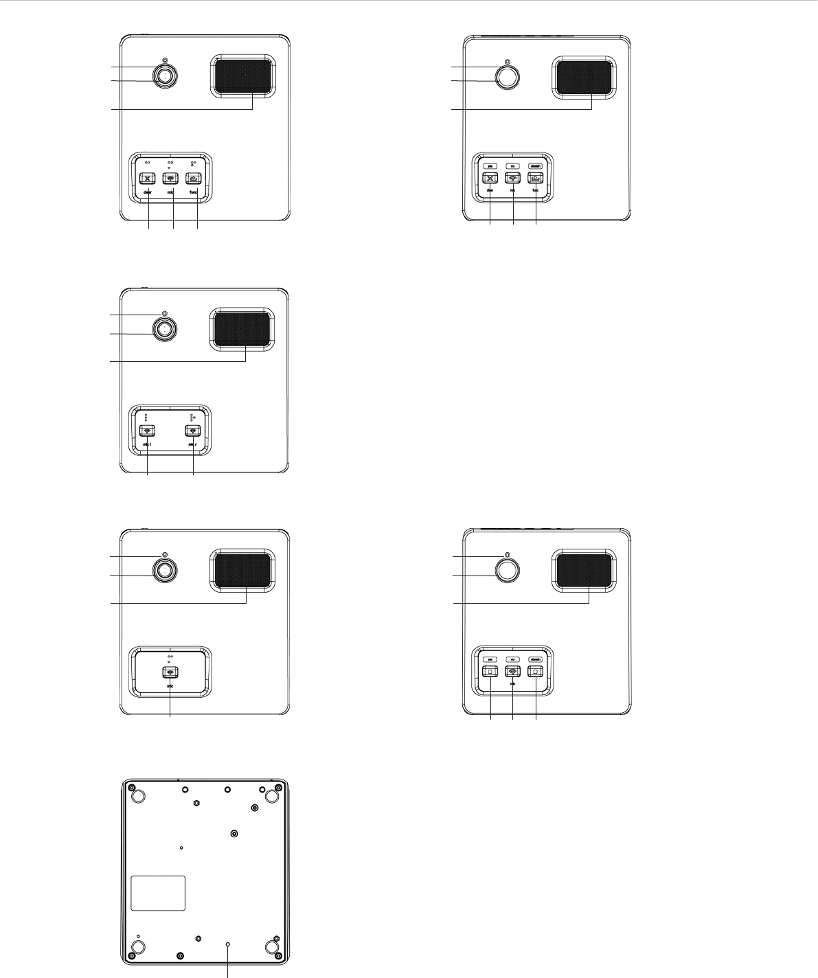
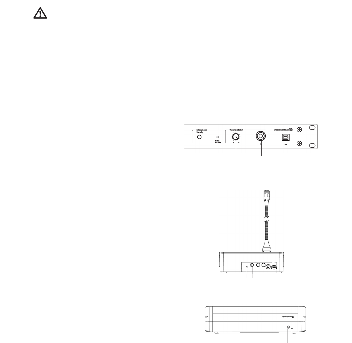
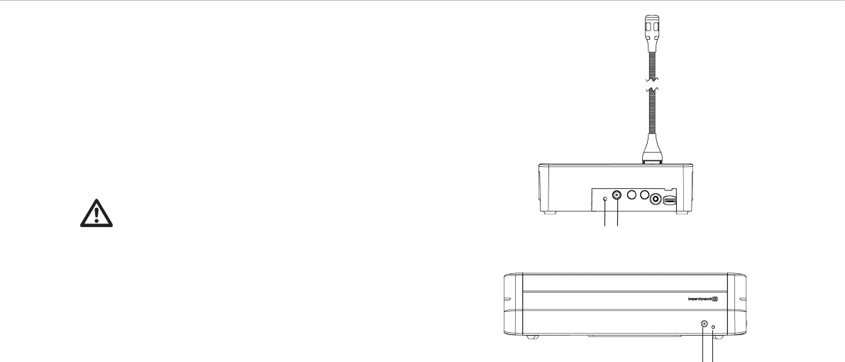
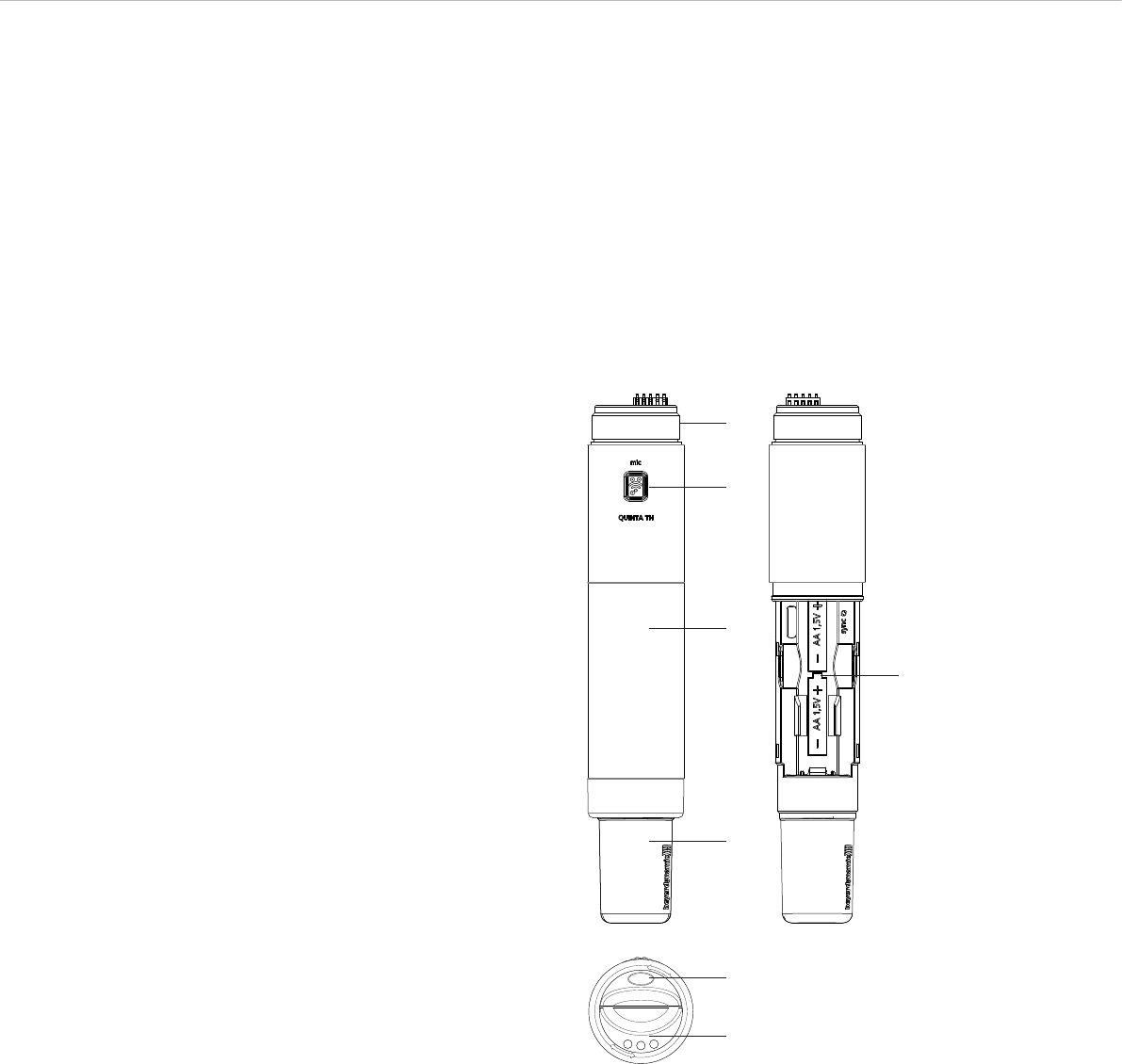
7.1 Controls and Indicators
ᕡThread to attach the microphone head
ᕢMicrophone button with braille inscription
ᕣBattery compartment cover
ᕤAntenna
ᕥBattery compartment
ᕦBattery indicator
ᕧCharging contacts
ᕡ
ᕢ
ᕣ
ᕥ
ᕤ
ᕦ
ᕧ
Quinta – Handheld Transmitter 29
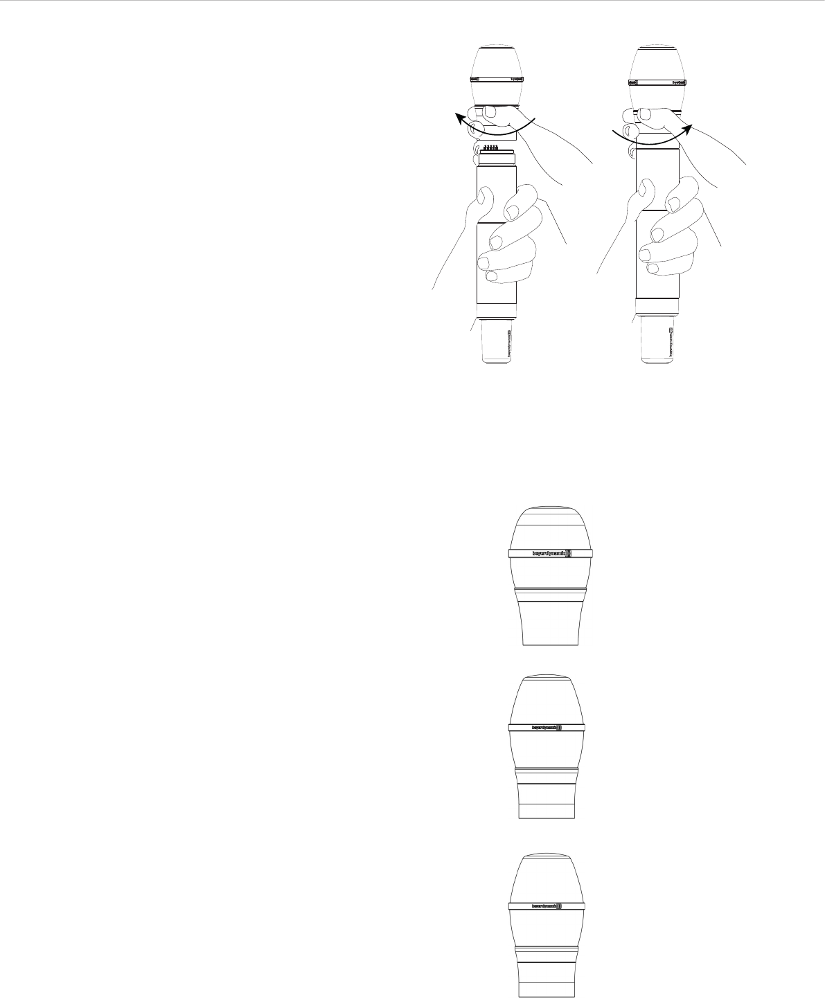
Tighten microphone
head clockwise.
Remove microphone
head by turning it anti-
clockwise.
TG V50w
Dynamic microphone head with cardioid polar pattern. Very wide
pick-up area, High gain before feedback.
TG V56w
Condenser microphone head with cardioid polar pattern. Discreet
treble boost. High gain before feedback. For conferences and
announcements.
7.2 How to Attach the Microphone Head
For the Quinta TH handheld transmitter there are different con-
denser and dynamic microphone capsules available. The micro-
phone head used is also displayed in the participant list of the
Quinta Conference Software. Refer also to “Optional Accessories”.
• Put the requested microphone head onto the thread of the hand-
held transmitter and tighten it clockwise.
• If you want to change the microphone head, unscrew it from the
transmitter by turning it anti-clockwise.
• Make sure that you switch off the handheld transmitter before
changing the microphone head.
TG V96w
Condenser microphone head with cardiod polar pattern. For vocals.
Uncoloured reproduction. Discreet treble boost for an open and
unobtrusive sound. High gain before feedback.
Quinta – Handheld Transmitter 30
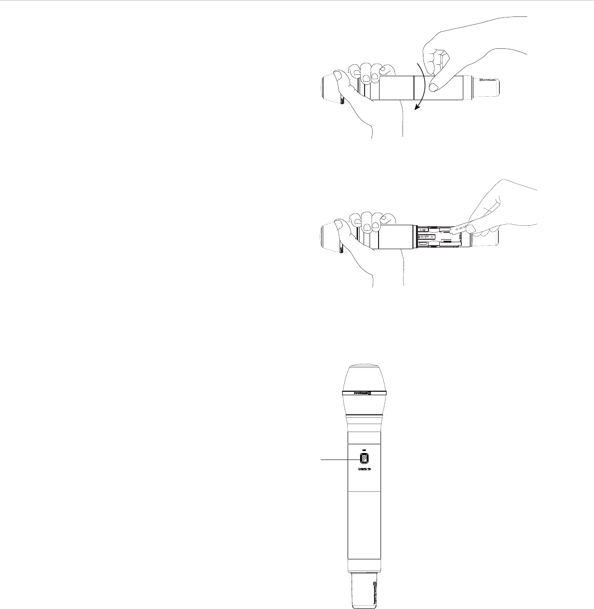
Unscrew cover of battery compartment and remove it.
Insert batteries according to the +/- symbols into the battery compartment.
7.3 How to Insert the Batteries
For operating the Quinta TH handheld transmitter you can use two
NiMH or alkaline (AA LR 6 Mignon) batteries.
• Unscrew the cover of the battery compartment as indicated by the
arrow.
• Slide the cover of the battery compartment downwards.
• Insert two NiMH rechargeable batteries or alkaline batteries
(AA LR 6 Mignon) according to the symbols in the battery
compartment.
• Slide the cover of the battery compartment upwards again and
tighten it.
• When the battery indicator at the bottom of the transmitter starts
to flash, the remaining operating time will be approx. 1 hour
depending on the battery type used.
• From time to time you should clean the battery and charging
contacts of the Quinta TH transmitter with a soft lint-free cloth
moistened with white spirit or alcohol. Please remove the batteries
from the battery compartment before cleaning.
7.4 Switching On/Off
Switching on and allocating the transmitter
• The handheld transmitter is switched on by pressing the micro-
phone button ᕢ. When the connection to the Quinta CU control
unit has been established, the microphone button ᕢ will
illuminate white to indicate the operating state.
• In order to activate the microphone or to allocate the microphone
to a free channel of the Quinta CU control unit, press the micro-
phone button ᕢ briefly once again. Depending on the operating
mode, the microphone button ᕢ will illuminate green (normal
operating mode) or red (request-to-speak mode).
Switching off
• By pressing the microphone button ᕢ (approx. 3 seconds) the
handheld transmitter is switched off.
• If you press the standby button of the control unit for more than
3 seconds, the handheld transmitter will be switched off.
• Furthermore, the handheld transmitter will be switched off
automatically, when it does not receive a signal from the Quinta
CU control unit for more than 3 minutes.
ᕢ

Quinta – Handheld Transmitter 31
7.5 Operating Modes
Normal
• Press the microphone button to switch on the handheld
transmitter. The button will illuminate white to display the ready
operating status.
• To activate the microphone, press the microphone button once
again. The microphone button will illuminate green. The micro-
phone is ready to speak into it.
• Using the Quinta CU control unit, up to 4 participants
(e.g. 3 delegates and 1 chairman) can speak simultaneously
depending on the setting.
• By pressing the microphone button for more than 3 seconds the
handheld transmitter is switched off. The microphone button
does not illuminate anymore.
FiFo mode (First in – First out)
• If the microphones operate in the FiFo mode (first in - first out),
the microphones that was switched on first, will be switched off,
when another microphone is switched on and the number of open
microphones (NOM) will be exceeded.
Push-To-Talk mode
• If the microphones operate in the Push-To-Talk mode (PTT), the
microphone button must be pressed as long as someone speaks
into the microphone. This configuration is recommended for
short interruptions during the meeting.
Voice Activation mode
• If the microphones operate in the Voice Activation mode, the
microphones are switched on via voice control. That is the
microphone is switched on as soon as someone speaks into the
microphone. In this case it is not necessary to press the micro-
phone button.
Important:
If the number of open microphones is exceeded, a
microphone can only be switched on manually when
another microphone has been switched off.
Important:
The threshold and the hold time can be configured with the
“Quinta Conference Software” for all microphones.
Request-to-Speak mode
• This operating mode is only possible in conjunction with a PC
using the Quinta Conference software or a media control
system (AMX®, Crestron®, Cue etc.).
• The request-to-speak is registered in the system by pressing the
microphone button of the microphone unit.
• The allocation is made by the operator at the PC or touch screen
of the media control system.
• The microphone button is illuminated red to indicate the
request-to-speak .
• If you press the microphone button again, the request-to-speak
is cleared. The backlit microphone button will illuminate white.
Quinta – Handheld Transmitter 32
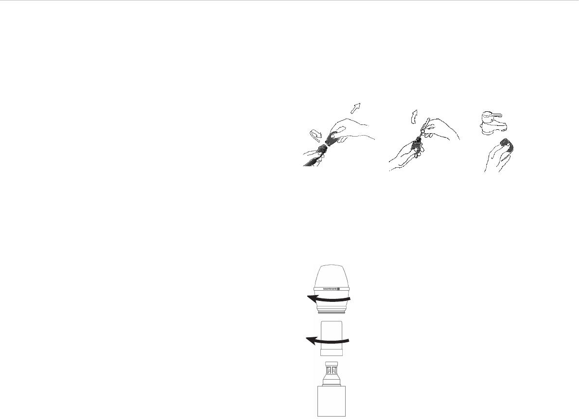
7.6 Maintenance
• Protect the handheld transmitter from humidity, knocks and
shock. Avoid dropping the transmitter at all times.
• For cleaning metal surfaces, use a soft cloth moistened with
methylated spirits or alcohol.
• As soon as your microphone sounds dull, you should clean the
integrated pop shield. Proceed as described in the following.
– Unscrew the microphone grille anti-clockwise.
– Pull out the foam pop shield, if necessary use tweezers and
clean it under clear running water.
– If necessary, use a mild washing-up liquid.
– Dry it afterwards with a hairdryer or allow it to dry overnight.
– Clean the microphone grille both inside and out with a slightly
moistened cloth or a soft brush under clear running water
and allow it to dry overnight.
– The microphone grille cannot be cleaned in a dishwasher.
– Place the dry pop shield inside the microphone grille and
replace the microphone grille by screwing it on clockwise.
– The TG V96w is provided with a mesh pop shield.
– For cleaning turn the microphone grille anti-clockwise to
unscrew.
– Turn the wire mesh pop shield anti-clockwise to unscrew.
– Clean the pop shield under clear running water.
– Allow the pop shield to dry overnight before you replace it.
– The wire mesh pop shield cannot be cleaned in a dishwasher.
– Clean the microphone grille inside and outside with a slightly
moistened cloth or a soft brush under clear running water and
allow it to dry overnight.
– The microphone grille cannot be cleaned in a dishwasher.
TG V96w
Quinta – Handheld Transmitter 33
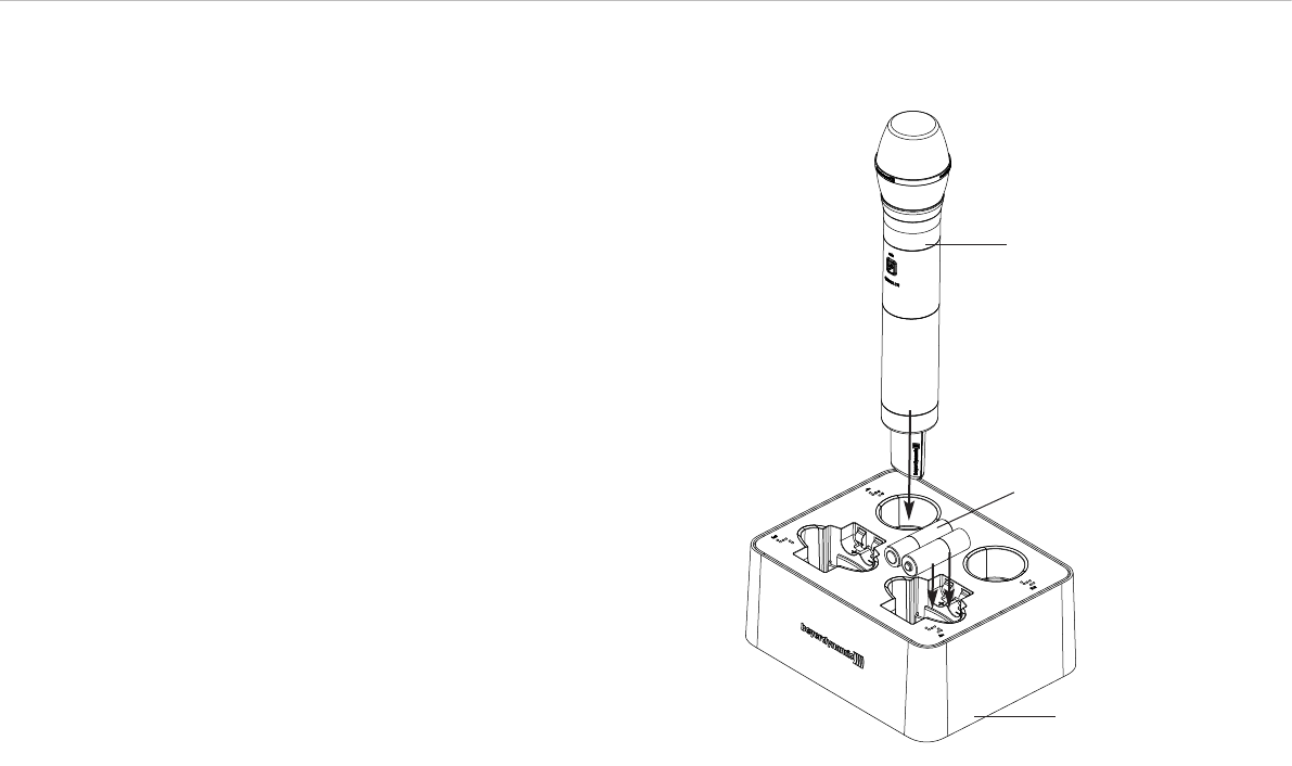
7.7 Charging
If the Quinta TH handheld transmitter is operated with NiMH
batteries, you can recharge it with the WA-CD charger. The
rechargeable batteries can remain inside the transmitter or be
charged separately. For a detailed description on the operation,
please refer to the separate manual for the “WA-CD” charger.
• Mount the appropriate power plug to the power adaptor.
• Connect the power adaptor to the charger and to the mains.
• The charger provides no separate on/off switch and will start up
automatically.
• The charging lights of the battery compartments will illuminate
white to indicate the ready operating status of the device.
• If required, connect the Ethernet port to a media control system.
• Put the Quinta TH handheld transmitter or the NiMH batteries
into the charging compartments as indicated in the drawing. If
the transmitter is turned on, it will be turned off automatically.
Make sure to insert the NiMH batteries into the charging
compartments as indicated by the +/- marks.
Important: Before charging please make sure that there are no
non-rechargeable alkaline batteries in the transmitter. The
simultaneous use of different batteries (alkaline and NiMH) in
one transmitter is not suitable for operating the transmitter,
furthermore these transmitters should not be charged, because
transmitter and charger could be damaged. In this case the
guarantee will be invalidated.
Each charging compartment is controlled separately. The appro-
priate indicators display the charging process.
Indicator illuminates white. . . . The charging compartment is
ready for operation.
Insert the transmitter.
Indicator is flashing green . . . . The batteries are being charged.
Indicator illuminates green. . . . The batteries are fully charged.
Indicator is flashing red . . . . . . Error. The charging process is not
started.
All indicators are
flashing rapidly red . . . . . . . . . Severe error. Do not use the
charger!
Note:
• If an indicator is flashing red, remove the appropriate
transmitter from the charging compartment and check if there
are alkaline batteries inside the transmitter or if the NiMH have
been inserted incorrectly. Should the flashing persist even when
using NiMH batteries, please check if the batteries are already
fully charged. If not, the batteries are defective and must be
replaced.
• Should all the indicators flash red rapidly, no matter if there are
transmitters in the charging compartments or not, there is a
severe error. Disconnect the charger from the mains and check
if there is a metallic object in the charging compartment. If yes,
remove the object and connect the charger to the mains again.
Should the indicators still flash rapidly, there is a defect, which
the user cannot fix. In this case, please contact an authorised
beyerdynamic dealer.
Quinta TH
handheld transmitter
NiMH batteries
WA-CD
charger
Quinta – Trouble Shooting 34
8. Trouble Shooting
If problems occur that you do not find listed below, reset the Quinta
system to the standard configuration with the Quinta Conference soft-
ware. Please refer alsoto the appropriate manual.
Problem Possible Cause Solution
Microphone button flashes red rapidly • Control unit is not switched on
• Microphone unit is not within the range
of the control unit
• Frequency bands have been configured
incorrectly
• Microphone unit does not have the
correct PIN code
• Switch on the control unit
• Reduce the distance between control unit
and microphone units
• Check the adjusted frequency bands with
the Quinta Conference software
• Deactivate the PIN function in the Quinta
Conference software. Make sure that all
microphone units to be configured with the
PIN code are within the range of the Quinta
CU control unit. Enter the requested PIN
code in the Quinta Conference software and
select “Send to MUs”. Activate the PIN
function in the Quinta Conference software
again. All microphone units that have
received the new PIN code will communi-
cate with the Quinta CU control unit. Other
microphone units will not communicate
(microphone button is flashing red).
Operating control LED ቢ flashes • Battery is almost empty
• Low battery warning to indicate that the
battery is almost empty
• Recharge the battery inside the micro-
phone unit
Microphone unit goes off • Check if the battery is still full
• PIN code is activated
• If the battery is empty, recharge it
• Deactivate PIN code
Microphone cannot be activated • All channels are occupied
• Check the number of open microphones
(NOM) with the Quinta Conference Soft-
ware or Quinta Web Server
• Microphone unit is not within the range
of the control unit
• Interference caused by WLAN
• System operates in the PC controlled
mode (Controller)
• All channels are reserved for chairmen
• Switch off an activated microphone
• If possible increase the NOM with the
Quinta Conference Software or the Quinta
Web Server
• Reduce the distance between control unit
and microphone units
• Use the standard settings mentioned in the
Quinta Conference Software manual
• Check the settings of the frequency bands
• Select another frequency band with the
Quinta Conference Software, the Quinta
Web Server or the push-button for RF
frequency band selection on the front of the
Quinta CU control unit
• Set the system into the autonomous
operating mode with the Quinta Conference
Software or the Quinta Web Server
• Do not reserve all channels for chairmen,
i.e. use less chairman units. Leave at least
one channel free for delegate units.
Microphone unit cannot be switched on • Check the battery • If the battery is empty, recharge it
Loudspeaker of the microphone unit does
not work
• Check the volume setting with the Quinta
Conference Software or Web Server
• Increase the volume with the Quinta
Conference Software or Quinta Web Server

Quinta – Trouble Shooting 35
Problem Possible Cause Solution
Microphone unit cannot be switched off • “Manual Power Off” function is
deactivated
• Operating mode “Push-To-Talk” or “Voice
activated” is active
• Crash of the microcontroller inside the
microphone unit
• Activate the “Manual Power Off” function
with the Quinta Conference Software or
Quinta Web Server
• Deactivate the operating mode “Push-To-
Talk” or “Voice activated” with the Quinta
Conference Software or Quinta Web Server
• Switch off the microphone units via the
control unit by pressing the Clear/Standby
button for more than 3 seconds
• Switch off the control unit. The microphone
units will go off after approx. 3 minutes.
• Press the reset button on the bottom of the
microphone unit
Headphone output of the microphone unit
does not work
• Microphone unit is not switched on
• Headphone or recorder is not connected
properly
• Check the volume setting with the Quinta
Conference Software or Quinta Web Server
• Switch on the microphone unit
• Connect the headphone or recorder
properly
• Increase the volume with the Quinta
Conference Software or Quinta Web Server
Feedback • Check the external loudspeakers • Correct the volume and position of the
loudspeakers
Interferences, noise • Check the audio level
• Microphone unit is not within the range
of the control unit
• Check the line of sight between micro-
phone unit and antenna
• Reduce the input level of the control unit
• Reduce the distance between control unit
and microphone units
• Remove obstacles between microphone
units and antennae; do not place any
objects in front of the antennae of the
control unit
Short drop-outs • Interferences caused by devices such as
Wireless LAN
• Select another frequency band with the
Quinta Conference Software, Quinta Web
Server or via the push-button for RF
frequency band selection on the front of
the Quinta CU control unit. Refer also to
chapter 7.1.
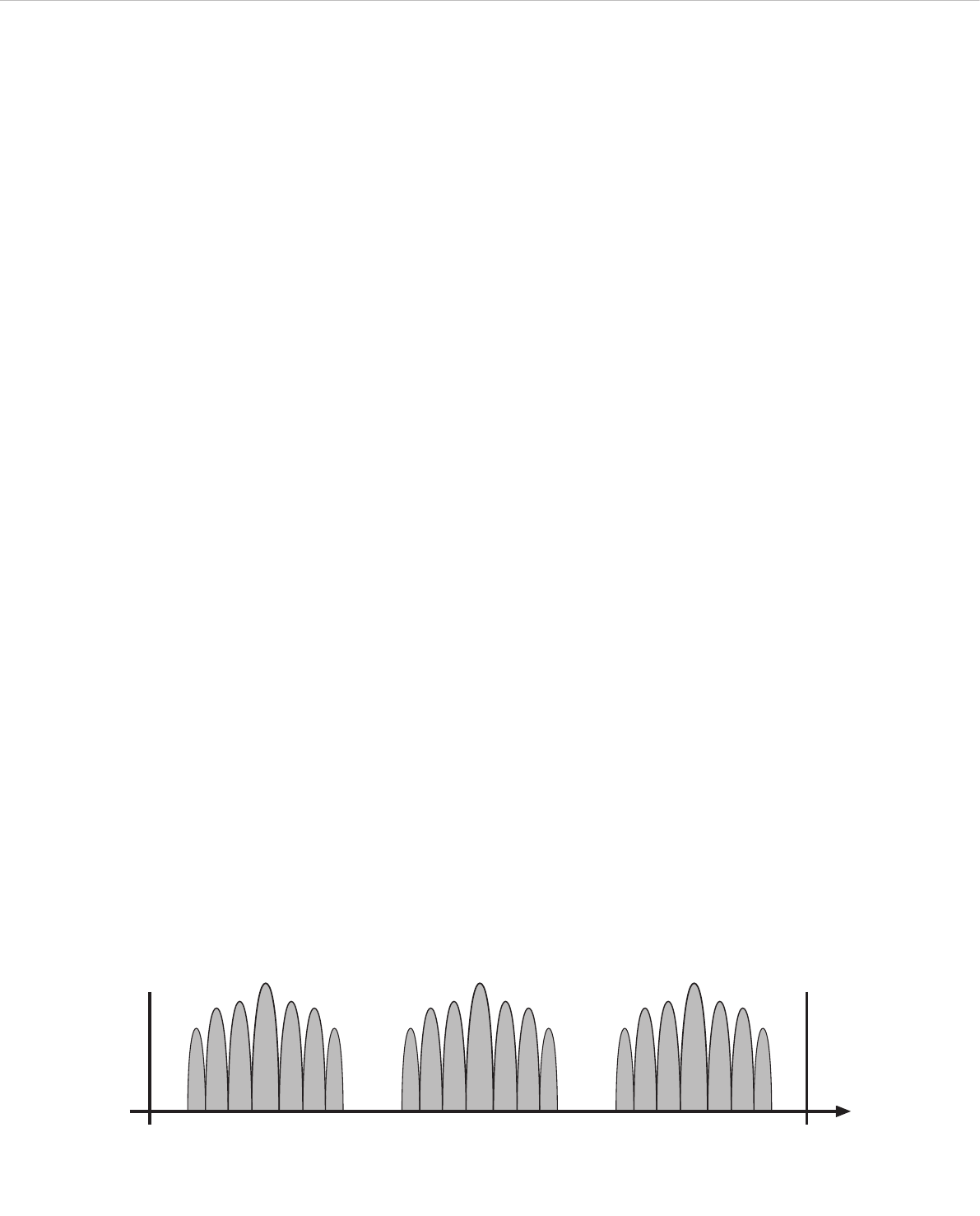
Quinta – Trouble Shooting 36
Frequencies Quinta / WLAN for example for 2.4 GHz
Quinta WLAN
Channel. . . Centre frequency Channel . . . . . . . . . . . . . . . . . Centre frequency
2.4 GHz 5.2 GHz 5.8 GHz
Low . . . . . 2412 MHz . . . . . . 5180 MHz . . . . . . 5736 MHz 1 . . . . . . . . . . . . . . . . . . . . . . 2412
2 . . . . . . . . . . . . . . . . . . . . . . 2417
3 . . . . . . . . . . . . . . . . . . . . . . 2422
4 . . . . . . . . . . . . . . . . . . . . . . 2427
5 . . . . . . . . . . . . . . . . . . . . . . 2432
Mid . . . . . 2438 MHz . . . . . . 5210 MHz . . . . . . 5762 MHz 6 . . . . . . . . . . . . . . . . . . . . . . 2437
7 . . . . . . . . . . . . . . . . . . . . . . 2442
8 . . . . . . . . . . . . . . . . . . . . . . 2447
9 . . . . . . . . . . . . . . . . . . . . . . 2452
10 . . . . . . . . . . . . . . . . . . . . . 2457
High . . . . . 2464 MHz . . . . . . 5240 MHz . . . . . . 5814 MHz 11 . . . . . . . . . . . . . . . . . . . . . 2462
12 . . . . . . . . . . . . . . . . . . . . . 2467
13 . . . . . . . . . . . . . . . . . . . . . 2472
14 . . . . . . . . . . . . . . . . . . . . . 2484
2400 MHz Low Mid High 2484 MHz
Frequency /
MHz
8.1 Simultaneous Operation of the Quinta Conference
System and other 2.4 GHz Devices
(e.g. WLAN, Bluetooth)
8.1.1 Physical Laws
Due to many physical laws it is not possible to guarantee a
simultaneous interference-free operation of different devices using
the same frequency band. Radio devices operating in the same
frequency band will always disturb each other (the function can be
disturbed as well).
For the use of UHF wireless microphones it is known that 2 devices
can never be operated on the same frequency. It is only possible to
operate a certain number of compatible radio devices within a
defined frequency band.
This applies also to the 2.4 GHz-ISM band (2400 MHz - 2484 MHz)
or 5 GHz. Due to digital transmission techniques and various
transmission standards it is possible, but not recommended, to
operate certain devices simultaneously within the same frequency
band.
8.1.2 Quinta and WLAN or WiFi
Like WLAN, the Quinta system uses the same bandwidth of approx.
22 MHz for each RF channel (Low, Mid, High). This results in three
compatible RF channels which are theoretically:
Compatible channel 1: 2400 MHz - 2428 MHz
(theoretical mid frequency 2414 MHz)
Compatible channel 2: 2428 MHz - 2456 MHz
(theoretical mid frequency 2442 MHz)
Compatible channel 3: 2456 MHz - 2484 MHz
(theoretical mid frequency 2470 MHz)
Compatible channel 4: +5.2 GHz - +5.8 GHz
The Quinta system uses RF channels (Low, Mid, High) compatible
to each other. For WLAN the user has to configure compatible RF
channels.
You can easily recognise that the individual WLAN channels overlap
considerably due to their bandwidth. All neighbouring channels
(e.g. channel 1 & 2 or channel 7 & 8) cannot be used simultane-
ously, because they would disturb each other. Furthermore, channel
12 and 13 are not approved for the use in the USA. In general, these
channels are not used either. Within the remaining frequency bands
only the WLAN channels 1, 6 and 11 can be used simultaneously.
For this reason the WLAN channels 1, 6 and 11 were selected for the
RF channels Low, Mid and High used for the Quinta conference
system. Due to this frequency compatibility the Quinta system is
operated WLAN-friendly.
More tips for installation
• Keep a minimum distance of approx. 5 m between WLAN
devices (e.g. Router, Repeater) and the transmitting and
receiving antennae of the Quinta CU control unit.
• The distance between laptops with activated WLAN interface
does not influence the audio transmission of the microphone
units as long as there is no active data traffic.
• We recommend using different RF channels for WLAN or WiFi
and Quinta channels. The distance between the WLAN and
Quinta channels should be as large as possible.
• The channels of the Quinta conference system can be selected
with the supplied Quinta Conference Software.

Quinta – Trouble Shooting 37
8.1.3 Quinta and Bluetooth
• Bluetooth devices make use of the whole 2.4 GHz range with
changing carrier frequencies (frequency hopping).
• Interferences caused by Bluetooth devices (including micro-
wave ovens) in normal operation can be excluded due to
different measures inside the Quinta conference system and
an advanced transmission protocol.
• It cannot be excluded, however, that an exisisting Bluetooth
data traffic will be intefered by Quinta.
8.1.4 Example for Quinta, Media Control System and
WLAN
The 2.4 GHz technology is used for many applications in
discussions and meetings. In addition to a wireless discussion
system other functions (light or volume control etc.) are operated
via a wireless 2.4 GHz touch screen of a media control system.
Furthermore, the participants of a meeting often have direct
internet access via a WLAN access point.
The Quinta conference system and WLAN make use of compatible
transmission standards. This should be considered when also
using a media control system with a touch screen. State-of the-art
devices correspond to the WLAN standard.
1. Configure the Quinta conference system to the RF channel
“Low”. The Quinta system then makes use of the frequency
range of 2401 to 2423 MHz. This frequency range must be
reserved for Quinta exclusively.
2. Configure the touch screen of the media control system to the
frequency range of 2426 to 2448 MHz. This corresponds to
the WLAN channel 6. This frequency range must be reserved
for the use of the touch screen exclusively.
3. Configure the WLAN access point to WLAN channel 11
making use of the frequency range 2451 to 2473 MHz. This
frequency range must be reserved for the use by WLAN
exclusively.
4. As an alternative you can operate Quinta in the 5.2 or 5.8 GHz
band.

Quinta – Components 38
10. Accessories
Supplied Accessories
1 Power cable
1 USB cable
6 Phoenix terminal strips, 3-pin
2 CA Q11 antennas
1 Unlocking tool
Quinta Conference Software for Control and Configuration . . . . . . . . . . . . . . . . . . . . . . . . . . . . . . . . . . . . . . . . . . . . Order # 723.991
Optional
Quinta CU Control Unit
CA Q 13 Planar antenna, 2.4 - 5.8 GHz . . . . . . . . . . . . . . . . . . . . . . . . . . . . . . . . . . . . . . . . . . . . . . . . . . Order # 724.408
CA Q 14 Omnidirectional antenna for remote installation . . . . . . . . . . . . . . . . . . . . . . . . . . . . . . . . . . . . . . Order # 723.894
CA Q 30 Ecoflex system coaxial cable, sold per metre. . . . . . . . . . . . . . . . . . . . . . . . . . . . . . . . . . . . . . . . . Order # 724.440
CA Q 31 Ecoflex system coaxial cable, 10 m [32.8 ft] . . . . . . . . . . . . . . . . . . . . . . . . . . . . . . . . . . . . . . . . Order # 724.416
CA Q 32 Ecoflex system coaxial cable, 20 m [65.6 ft] . . . . . . . . . . . . . . . . . . . . . . . . . . . . . . . . . . . . . . . . Order # 724.424
Gooseneck Microphones for the Quinta MU 23/22/21 Microphone Units
Classis GM 313 Q Gooseneck microphone, condenser, cardioid, black, length 300 mm [11.81"],
LED, 5-pin XLR connector, incl. wind shield. . . . . . . . . . . . . . . . . . . . . . . . . . . . . . . . . . . . . . . . . Order # 724.203
Classis GM 314 Q Gooseneck microphone, condenser, cardioid, black, length 400 mm [15.75"], LED,
5-pin XLR connector, incl. wind shield. . . . . . . . . . . . . . . . . . . . . . . . . . . . . . . . . . . . . . . . . . . . . Order # 724.211
Classis GM 315 Q Gooseneck microphone, condenser, cardioid, black, length 500 mm [19.69"], LED,
5-pin XLR connector, incl. wind shield. . . . . . . . . . . . . . . . . . . . . . . . . . . . . . . . . . . . . . . . . . . . . Order # 724.238
Classis GM 316 Q Gooseneck microphone, condenser, cardioid, black, length 600 mm [23.62"], LED,
5-pin XLR connector, incl. wind shield. . . . . . . . . . . . . . . . . . . . . . . . . . . . . . . . . . . . . . . . . . . . . Order # 724.351
Quinta CC 2 | CC 2 / 600 Charging and Transport Case
Quinta CD 2 Charger for 10 Quinta MU 23/22/21 microphone units . . . . . . . . . . . . . . . . . . . . . . . . . . . . . . . . . Order # 723.975
Quinta CM 2 19" compartment for Quinta CU control unit. . . . . . . . . . . . . . . . . . . . . . . . . . . . . . . . . . . . . . . . . Order # 724.661
Quinta CT 2 Top cover . . . . . . . . . . . . . . . . . . . . . . . . . . . . . . . . . . . . . . . . . . . . . . . . . . . . . . . . . . . . . . . . . Order # 724.556
Quinta CT 2/600 Top cover, when using the microphone units with the Classis GM 316 Q microphone . . . . . . . . . . . . Order # 724.580
Quinta CW 2 Bottom with casters . . . . . . . . . . . . . . . . . . . . . . . . . . . . . . . . . . . . . . . . . . . . . . . . . . . . . . . . . . Order # 724.564
Quinta CC 3 Charging and Transport Case
Quinta CD 3 Charger for 12 Quinta MU 33/31 microphone units. . . . . . . . . . . . . . . . . . . . . . . . . . . . . . . . . . . . Order # 725.137
Quinta CM 2 19" compartment for Quinta CU control unit. . . . . . . . . . . . . . . . . . . . . . . . . . . . . . . . . . . . . . . . . Order # 724.661
Quinta CT 2 Top cover . . . . . . . . . . . . . . . . . . . . . . . . . . . . . . . . . . . . . . . . . . . . . . . . . . . . . . . . . . . . . . . . . Order # 724.556
Quinta CW 2 Bottom with casters . . . . . . . . . . . . . . . . . . . . . . . . . . . . . . . . . . . . . . . . . . . . . . . . . . . . . . . . . . Order # 724.564
9. Components
Quinta CU Control unit, DSSS transmission in 2.4 / 5.2 / 5.8 GHz ISM bands,
4 receive channels, 19" housing, 1 U, incl. 2 angled rod antennae,
matt black, with high-resolution OLED display . . . . . . . . . . . . . . . . . . . . . . . . . . . . . . . . . . . . . . . Order # 723.924
Quinta MU 23 Chairman microphone unit, removable Classis GM 31x Q gooseneck microphone (optional),
DSSS transmission (Triple-RF-ISM-Band), incl. rechargeable battery, with loudspeaker and three buttons,
soft touch paint, matt black . . . . . . . . . . . . . . . . . . . . . . . . . . . . . . . . . . . . . . . . . . . . . . . . . . . . Order # 723.932
Quinta MU 22 Double delegate microphone unit, removable Classis GM 31x Q gooseneck microphone (optional),
DSSS transmission (Triple-RF-ISM-Band), incl. rechargeable battery, with loudspeaker
and two microphone buttons, soft touch paint, matt black . . . . . . . . . . . . . . . . . . . . . . . . . . . . . . . Order # 723.940
Quinta MU 21 Delegate microphone unit, removable Classis GM 31x Q gooseneck microphone (optional),
DSSS transmission (Triple-RF-ISM-Band), incl. rechargeable battery, with loudspeaker
and one microphone button, soft touch paint, matt black . . . . . . . . . . . . . . . . . . . . . . . . . . . . . . . Order # 723.959
Quinta MU 33 Chairman microphone unit, Revoluto technology, DSSS transmission (Triple-RF-ISM-Band),
incl. rechargeable battery, with loudspeaker and three buttons, soft touch paint, matt black . . . . . . . Order # 725.102
Quinta MU 31 Delegate microphone unit, Revoluto technology, DSSS transmission (Triple-RF-ISM-Band),
incl. rechargeable battery, with loudspeaker and one microphone button, soft touch paint, matt black Order # 725.110
Quinta CC 2 Charging case for 10 Quinta MU 23/22/21 microphone units with GM 313/314/315 Q, consisting of:
Quinta CT 2 top cover, Quinta CD 2 charger, Quinta CW 2 bottom with casters . . . . . . . . . . . . . . . . Order # 723.967
Quinta CC 2/600 Charging case for 10 Quinta MU 23/22/21 microphone units with Classis GM 316 Q, consisting of:
Quinta CT 2 / 600 top cover, Quinta CD 2 charger, Quinta CW 2 bottom with casters . . . . . . . . . . . . Order # 724.580
Quinta CC 3 Charging case for 12 Quinta MU 33/31 microphone units, consisting of:
Quinta CT 2 top cover, Quinta CD 3 charger, Quinta CW 2 bottom with casters . . . . . . . . . . . . . . . . Order # 725.129
CA 2459 Mains power adapter with charging function and DC power supply for one Quinta MU microphone unit. . Order # 729.493
Quinta TH Digital handheld transmitter with metal housing, silicone button with braille inscription, without
microphone head, incl. 2 x AA NiMH batteries, MKV 11 microphone clamp and bag for transport . . . Order # 729.329

Quinta – Technical Specifications 39
Quinta TH Handheld Transmitter
Interchangeable Microphone Capsules
TG V50w Dynamic, cardioid, incl. storage bag . . . . . . . . . . . . . . . . . . . . . . . . . . . . . . . . . . . . . . . . . . . . . . Order # 711.438
TG V56w Electret condenser, cardioid, incl. storage bag . . . . . . . . . . . . . . . . . . . . . . . . . . . . . . . . . . . . . . . Order # 711.446
TG V96w True condenser, cardioid, incl. storage bag . . . . . . . . . . . . . . . . . . . . . . . . . . . . . . . . . . . . . . . . . . Order # 711.470
Charger
WA-CD Charger for TG 1000 beltpack transmitter and Quinta TH handheld transmitter with 4 charging
compartments and control via Ethernet . . . . . . . . . . . . . . . . . . . . . . . . . . . . . . . . . . . . . . . . . . . . Order # 711.144
11. Technical Specifications
General
Frequency range . . . . . . . . . . . . . . . . . . . . . . . . . . . . . . . 2400 – 2483.5 MHz
5150 – 5250 MHz
5725 – 5875 MHz
Modulation . . . . . . . . . . . . . . . . . . . . . . . . . . . . . . . . . . . DSSS (Direct Sequence Spread Spectrum) and
QPSK/BPSK (Quadrature/Binary Phase Shift Keying)
digital signal processing acc. to own standard
Max. number of audio streams . . . . . . . . . . . . . . . . . . . . . 4 useable channels per system
Signal-to-noise ratio . . . . . . . . . . . . . . . . . . . . . . . . . . . . . 80 dB typ., (unweighted signal-to-noise ratio)
Range between microphone units and control unit . . . . . . . > 100 m [109.36 yds]
Power supply. . . . . . . . . . . . . . . . . . . . . . . . . . . . . . . . . . 100 – 240 V AC 50/60 Hz
Approval . . . . . . . . . . . . . . . . . . . . . . . . . . . . . . . . . . . . . world-wide
AVB
Transmission and reception
of audio data. . . . . . . . . . . . . . . . . . . . . . . . . . . . . . . . . . acc. to IEC 61883-6
Format of the audio data . . . . . . . . . . . . . . . . . . . . . . . . . AM824
Stream ID Quinta CU . . . . . . . . . . . . . . . . . . . . . . . . . . . . Bit 63 – 16 / MAC address
Bit 15 – 0 / X
Quinta MU 23/22/21 Microphone Units
Transmitter power . . . . . . . . . . . . . . . . . . . . . . . . . . . . . . max. 20 dBm per channel and region (average, duty cycle ≤ 30%)*
Battery voltage . . . . . . . . . . . . . . . . . . . . . . . . . . . . . . . . 8 NiMH cells, 2080 mAh
External DC operation . . . . . . . . . . . . . . . . . . . . . . . . . . . 15 V DC (±0.5 V), residual hum < 20 mV, 950 mA
Charging time with charger . . . . . . . . . . . . . . . . . . . . . . . . max. 2.5 hours when the battery is completely empty
with mains charger adapter. . . . . . . . . . . . . . . . . . . . . . . . max. 2.5 hours when the battery is completely empty
Loudspeaker . . . . . . . . . . . . . . . . . . . . . . . . . . . . . . . . . . Wide-band, integrated loudspeaker
Volume decrease when Mic On (“Ducking”) . . . . . . . . . . . . 15 dB fixed setting
Headphone output . . . . . . . . . . . . . . . . . . . . . . . . . . . . . . Jack socket (3.5 mm, stereo)
Min. impedance . . . . . . . . . . . . . . . . . . . . . . . . . . . . . . . 16 Ω
Power supply. . . . . . . . . . . . . . . . . . . . . . . . . . . . . . . . . . 9.6 V with integrated NiMH battery (8 cells)
Operating time depending on the type of
the microphone unit. . . . . . . . . . . . . . . . . . . . . . . . . . . . . approx. 20 hours in discussion mode, operating time also depends on the
volume
Temperature range (at < 90% humidity). . . . . . . . . . . . . . . +10° – +40°C [+50 °F – +104 °F]
Storage temperature (at < 90% humidity) . . . . . . . . . . . . . -20° – +55°C [-4 °F – +131 °F]
Dimensions (without microphone) . . . . . . . . . . . . . . . . . . . Length 173 mm [6.8"]
Width 157 mm [6.18"]
Height 51 mm [2.01"]
Weight . . . . . . . . . . . . . . . . . . . . . . . . . . . . . . . . . . . . . . 1.7 kg [3.74 lbs]
Quinta MU 33/31 Microphone Units
Transmitter power . . . . . . . . . . . . . . . . . . . . . . . . . . . . . . max. 20 dBm per channel (average, duty cycle ≤ 30%)*
Battery voltage . . . . . . . . . . . . . . . . . . . . . . . . . . . . . . . . 8 NiMH cells, 2080 mAh
External DC operation . . . . . . . . . . . . . . . . . . . . . . . . . . . 15 V DC (±0.5 V), residual hum < 20 mV, 400 mA
Charging time with charger . . . . . . . . . . . . . . . . . . . . . . . . max. 2.5 hours when the battery is completely empty
with mains charger adapter. . . . . . . . . . . . . . . . . . . . . . . . max. 2.5 hours when the battery is completely empty
Microphone. . . . . . . . . . . . . . . . . . . . . . . . . . . . . . . . . . . Microphone Array
Pick up pattern . . . . . . . . . . . . . . . . . . . . . . . . . . . . . . . . Corridor
T.H.D.. . . . . . . . . . . . . . . . . . . . . . . . . . . . . . . . . . . . . . . < 0.1%
Loudspeaker . . . . . . . . . . . . . . . . . . . . . . . . . . . . . . . . . . Integrated, two-way loudspeaker
Loudspeaker switch off at “Mic On” . . . . . . . . . . . . . . . . . yes
Headphone output . . . . . . . . . . . . . . . . . . . . . . . . . . . . . . . . jack socket (3.5 mm, stereo)
Min. impedance . . . . . . . . . . . . . . . . . . . . . . . . . . . . . . . 16 Ω
Power supply. . . . . . . . . . . . . . . . . . . . . . . . . . . . . . . . . . 9.6 V with integrated NiMH battery (8 cells)

Quinta – Technical Specifications 40
Operating time depending on the type
of the microphone unit . . . . . . . . . . . . . . . . . . . . . . . . . . . approx. 20 hours in discussion mode; operating time depends on the volume
Temperature range (at < 90% humidity). . . . . . . . . . . . . . . +10° – +40°C [+50 °F – +104 °F]
Storage temperature (at < 90% humidity) . . . . . . . . . . . . . 20° – +55°C [-4 °F – +131 °F]
Dimensions . . . . . . . . . . . . . . . . . . . . . . . . . . . . . . . . . . . Length 96 mm [3.8"]
Width 300 mm [11.8"]
Height 82 mm [3.2"]
Weight . . . . . . . . . . . . . . . . . . . . . . . . . . . . . . . . . . . . . . 1.06 kg [2.33 lbs]
Quinta TH Handheld Transmitter
Operating principle . . . . . . . . . . . . . . . . . . . . . . . . . . . . . Digital triple band handheld transmitter
Frequency range . . . . . . . . . . . . . . . . . . . . . . . . . . . . . . . 2400 – 2483.5 MHz
5150 – 5250 MHz
5725 – 5875 MHz
Modulation . . . . . . . . . . . . . . . . . . . . . . . . . . . . . . . . . . . DSSS (Direct Sequence Spread Spectrum) and
QPSK/BPSK (Quadrature/ Binary Phase Shift Keying)
digital signal processing acc. to own standards
Max. number of audio streams . . . . . . . . . . . . . . . . . . . . . 4 usable channels per system
Signal-to-noise ratio . . . . . . . . . . . . . . . . . . . . . . . . . . . . . 80 dB typ., (unweighted signal-to-noise ratio)
Range between handheld transmitter and control unit . . . . . > 100 m [109.36 yds] with a direct line of sight
. . . . . . . . . . . . . . . . . . . . . . . . . . . . . . . . . . . . . . . . . . . (depending on the frequency band)
Power supply. . . . . . . . . . . . . . . . . . . . . . . . . . . . . . . . . . 100 – 240 V AC 50/60 Hz
Approval . . . . . . . . . . . . . . . . . . . . . . . . . . . . . . . . . . . . . world-wide
Transmitter power . . . . . . . . . . . . . . . . . . . . . . . . . . . . . . max. 20 dBm per channel and region (average, duty cycle ≤ 30%)*
Max. SPL . . . . . . . . . . . . . . . . . . . . . . . . . . . . . . . . . . . . 107 dBU SPL @ 1% THD (with TG V56w)
Internal PGA . . . . . . . . . . . . . . . . . . . . . . . . . . . . . . . . . . +25 dB
Power supply. . . . . . . . . . . . . . . . . . . . . . . . . . . . . . . . . . 2.4 V via 2x AA NiMH batteries
3 V via 2x AA alkaline batteries
Operating time . . . . . . . . . . . . . . . . . . . . . . . . . . . . . . . . approx. 10 hrs
(depending on the battery type and frequency band)
Charging time . . . . . . . . . . . . . . . . . . . . . . . . . . . . . . . . . max. 2.5 hours when the battery is completely empty
Temperature range (at < 90% humidity). . . . . . . . . . . . . . . +10° – +40°C [+50 °F – +104 °F]
Storage temperature (at < 90% humidity) . . . . . . . . . . . . . -20° – +55°C [-4 °F – +131 °F]
Dimensions . . . . . . . . . . . . . . . . . . . . . . . . . . . . . . . . . . . Length 197 mm [7.76"] / Ø 36 mm [1.42"] (without microphone head)
Weight . . . . . . . . . . . . . . . . . . . . . . . . . . . . . . . . . . . . . . 161 g [5.68 ozs] (without batteries and microphone head)
Quinta CU Control Unit
Frequency response . . . . . . . . . . . . . . . . . . . . . . . . . . . . . 70 Hz – 22 kHz (-3 dB)
Operation mode . . . . . . . . . . . . . . . . . . . . . . . . . . . . . . . . Diversity (receiver), separatefor each channel
Antenna connection . . . . . . . . . . . . . . . . . . . . . . . . . . . . . 2 N-connectors (female)
Transmitting power. . . . . . . . . . . . . . . . . . . . . . . . . . . . . . max. 20 dBm per channel and region (average, duty cycle ≤ 30%)*
Connections
Serial control port . . . . . . . . . . . . . . . . . . . . . . . . . . . . . . RS 232, USB
Ethernet port. . . . . . . . . . . . . . . . . . . . . . . . . . . . . . . . . . LAN, TCP/IP standard
Master output balanced . . . . . . . . . . . . . . . . . . . . . . . . . . 1 x XLR, 1 x 3-pin Phoenix terminal strip, max. +6 dBu,
level adjustable via software (range ±15 dB)
Master output unbalanced . . . . . . . . . . . . . . . . . . . . . . . . RCA, max. +2.2 dBu, level adjustable via software (range ±15 dB)
Audio outputs, single channels . . . . . . . . . . . . . . . . . . . . . 4 x 3-pin Phoenix terminal strip, max. +6 dBu, level adjustable via software
(range 0 ... -50 dB)
Input balanced . . . . . . . . . . . . . . . . . . . . . . . . . . . . . . . . 1 x 3-pin Phoenix terminal strip, max. +6 dBu, input adjustable via software
(range 0 ... -50 dB)
Power supply. . . . . . . . . . . . . . . . . . . . . . . . . . . . . . . . . . 100 – 240 V AC 50/60 Hz 70 – 150 mA
Fuse. . . . . . . . . . . . . . . . . . . . . . . . . . . . . . . . . . . . . . . . 2 x AL 0.5 A (slow blow)
Power consumption . . . . . . . . . . . . . . . . . . . . . . . . . . . . . 10 VA
Temperature range . . . . . . . . . . . . . . . . . . . . . . . . . . . . . . +10° – +40 °C [+50 °F – +104 °F] (at < 90% humidity)
Indication . . . . . . . . . . . . . . . . . . . . . . . . . . . . . . . . . . . . 4 channel LEDs (red/white) and Power LED (red/white)
Min. depth of Rack . . . . . . . . . . . . . . . . . . . . . . . . . . . . . 380 mm
Dimensions (W x H x D) . . . . . . . . . . . . . . . . . . . . . . . . . . 19", 1HU (440 x 44 x 239 mm) [17.32" x 1.73" x 9.41"]
Weight . . . . . . . . . . . . . . . . . . . . . . . . . . . . . . . . . . . . . . 3.2 kg [7.05 lbs]
AVB interface:
Stream ID . . . . . . . . . . . . . . . . . . . . . . . . . . . . . . . . . . . . Bit 63 – 16 / MAC address
Bit 15 – 0 / X
Number of channels. . . . . . . . . . . . . . . . . . . . . . . . . . . . . 4
Audio format . . . . . . . . . . . . . . . . . . . . . . . . . . . . . . . . . . IEC 61883-6/AM824 with 24-bit / 48 kHz
IP configuration. . . . . . . . . . . . . . . . . . . . . . . . . . . . . . . . DHCP

Quinta – Technical Specifications 41
Quinta CD 2 / CD 3 Charger
Power supply . . . . . . . . . . . . . . . . . . . . . . . . . . . . . . . . . . . . 100 - 240 V AC
˜
, 50 / 60 Hz
Fuse at the mains socket . . . . . . . . . . . . . . . . . . . . . . . . . 2 x 6.3 A (slow blow)
Power consumption . . . . . . . . . . . . . . . . . . . . . . . . . . . . . max. 180 W
Max. ambient temperature when charging
(< 90% atmospheric humidity) . . . . . . . . . . . . . . . . . . . . . +10 °C – +35 °C [+50 °F – +95 °F]
Storage temperature. . . . . . . . . . . . . . . . . . . . . . . . . . . . . -20 °C – +55 °C [-4 °F – +131 °F]
Charging unit . . . . . . . . . . . . . . . . . . . . . . . . . . . . . . . . . 10 microphone units parallel
Charging time . . . . . . . . . . . . . . . . . . . . . . . . . . . . . . . . . max. 3.5 hours when the battery is completely empty
Dimensions (W x H x D) . . . . . . . . . . . . . . . . . . . . . . . . . . 757 x 476 x 370 mm [29.8" x 18.74" x 14.57"]
Weight . . . . . . . . . . . . . . . . . . . . . . . . . . . . . . . . . . . . . . approx. 12 kg
CA 2459 Mains Power Adapter
Voltage . . . . . . . . . . . . . . . . . . . . . . . . . . . . . . . . . . . . . . 15 V DC
Current carrying capacity . . . . . . . . . . . . . . . . . . . . . . . . . 1.6 A
Input voltage . . . . . . . . . . . . . . . . . . . . . . . . . . . . . . . . . . 100 – 240 V AC 50/60 Hz
Connector . . . . . . . . . . . . . . . . . . . . . . . . . . . . . . . . . . . . Adapter for Europe, USA, UK, Australia
*The transmitter power can differ from this value due to specific regulations in various countries.

Quinta – EC Declaration of Conformity 42
EC-DECLARATION
OF CONFORMITY
Application of
Council directive: 1999/5/EC
R&TTE Directive
93/68/EEC
Electromagnetic Compatibility
2006/95/EC
Low Voltage Directive
Standards to which
Conformity is Declared: EMC EN 301 489-1 V1.8.1
EN 301 489-17 V2.1.1
Radio Spectrum EN 300 328 V1.8.0
EN 301 893 V1.5.1
EN 300 440-1 V1.6.1
EN 300 440-2 V1.4.1
Safety EN 60 950-1
Manufacturer’s Name: beyerdynamic GmbH & Co. KG
Manufacturer’s Address: Theresienstraße 8, 74072 Heilbronn, Germany
Type of Equipment: Wireless Conference System
Quinta
Model Numbers: Quinta CU
I, the undersigned, as an employee of beyerdynamic, hereby declare that the equipment specified conforms to
the above Directive and Standards.
Manufacturer’s Signature:
Date: 1st June, 2012
Full Name: Ulrich Roth
Position: Director of R&D
0682 !

Quinta – EC Declaration of Conformity 43
EC-DECLARATION
OF CONFORMITY
Application of
Council directive: 1999/5/EC
R&TTE Directive
93/68/EEC
Electromagnetic Compatibility
2006/95/EC
Low Voltage Directive
Standards to which
Conformity is Declared: EMC EN 301 489-1 V1.8.1
EN 301 489-17 V2.1.1
Radio Spectrum EN 300 328 V1.8.0
EN 301 893 V1.5.1
EN 300 440-1 V1.6.1
EN 300 440-2 V1.4.1
Safety EN 60 950-1
Manufacturer’s Name: beyerdynamic GmbH & Co. KG
Manufacturer’s Address: Theresienstraße 8, 74072 Heilbronn, Germany
Type of Equipment: Wireless Conference System
Quinta
Model Numbers: Quinta MU 21, Quinta MU 22, Quinta MU 23
Quinta MU 31, Quinta MU 33
I, the undersigned, as an employee of beyerdynamic, hereby declare that the equipment specified conforms to
the above Directive and Standards.
Manufacturer’s Signature:
Date: 1st July, 2013
Full Name: Ulrich Roth
Position: Director of R&D
0682 !

Quinta – EC Declaration of Conformity 44
EC-DECLARATION
OF CONFORMITY
Application of
Council directive: 1999/5/EC
R&TTE Directive
93/68/EEC
Electromagnetic Compatibility
2006/95/EC
Low Voltage Directive
Standards to which
Conformity is Declared: EMC EN 301 489-1 V1.8.1
EN 301 489-17 V2.1.1
Radio Spectrum EN 300 328 V1.8.0
EN 301 893 V1.5.1
EN 300 440-1 V1.6.1
EN 300 440-2 V1.4.1
Safety EN 60 950-1:2014
Manufacturer’s Name: beyerdynamic GmbH & Co. KG
Manufacturer’s Address: Theresienstraße 8, 74072 Heilbronn, Germany
Type of Equipment: Wireless Conference System
Model Numbers: Quinta TH
I, the undersigned, as an employee of beyerdynamic, hereby declare that the equipment specified conforms to
the above Directive and Standards.
Manufacturer’s Signature:
Date: 1st May, 2015
Full Name: Ulrich Roth
Position: Director of R&D
0682 !

Quinta – FCC Regulation 45
FCC Regulation
FCC ID: OSDQUINTACU for Quinta CU
FCC ID: OSDQUINTAMU2X for Quinta MU 21
FCC ID: OSDQUINTAMU2X for Quinta MU 22
FCC ID: OSDQUINTAMU2X for Quinta MU 23
FCC ID: OSDQUINTAMU3X for Quinta MU 31
FCC ID: OSDQUINTAMU3X for Quinta MU 33
FCC ID: OSDQUINTATH for Quinta TH
Canada: IC: 3628A-QUINTACU for Quinta CU
Canada: IC: 3628A-QUINTAMU2X for Quinta MU 21
Canada: IC: 3628A-QUINTAMU2X for Quinta MU 22
Canada: IC: 3628A-QUINTAMU2X for Quinta MU 23
Canada: IC: 3628A-QUINTAMU3X for Quinta MU 31
Canada: IC: 3628A-QUINTAMU3X for Quinta MU 33
Canada: IC: 3628A-QUINTATH for Quinta TH
Part 15.19 Statement
NOTICE:
This device complies with Part 15 of the FCC Rules [and with Industry Canada licence-exempt RSS standard(s)].
Operation is subject to the following two conditions:
(1) this device may not cause harmful interference, and
(2) this device must accept any interference received, including interference that may cause undesired operation.
Le présent appareil est conforme aux CNR d'Industrie Canada applicables aux appareils radio
exempts de licence. L’exploitation est autorisée aux deux conditions suivantes:
(1) l’appareil ne doit pas produire de brouillage, et
(2) l’utilisateur de l'appareil doit accepter tout brouillage radioélectrique subi, même si le brouillage est susceptible d’en compromettre le
fonctionnement.
Part 15.21 Statement
NOTICE:
Changes or modifications made to this equipment not expressly approved by beyerdynamic GmbH & Co. KG may void the FCC authorization
to operate this equipment.
Part 15.105 Statement
NOTE: This equipment has been tested and found to comply with the limits for a Class B digital device, pursuant to Part 15 of the FCC Rules.
These limits are designed to provide reasonable protection against harmful interference in a residential installation. This equipment gene-
rates, uses and can radiate radio frequency energy and, if not installed and used in accordance with the instructions, may cause harmful
interference to radio communications. However, there is no guarantee that interference will not occur in a particular installation. If this equip-
ment does cause harmful interference to radio or television reception, which can be determined by turning the equipment off and on, the
user is encouraged to try to correct the interference by one or more of the following measures:
• Reorient or relocate the receiving antenna.
• Increase the separation between the equipment and receiver.
• Connect the equipment into an outlet on a circuit different from that to which the receiver is connected.
• Consult the dealer or an experienced radio/TV technician for help.
RF Exposure Statement
Radiofrequency radiation exposure Information:
This equipment complies with FCC radiation exposure limits set forth for an uncontrolled environment.
This equipment should be installed and operated with minimum distance of 20 cm between the radiator and your body.
This transmitter must not be co-located or operating in conjunction with any other antenna or transmitter.
Special instructions for Japan:
Operation of these devices in the 5.8GHz range is illegal in Japan.
The CA Q 13 and CA Q 14 antenna may only be operated with at least 10m cable between antenna and control unit.
This device is granted pursuant to the Japanese Radio Law (電波法) and the Japanese Telecommunications Business Law (電気通信事業法)
•本製品は、電波法および電気通信事業法に基づき許可されています。
• This device should not be modified (otherwise the granted designation number will become invalid) (refer to attached Instruction File Japan
(R&T) 2012)).

E7/BA Quinta System (04.15) •
Subject to change without notice
beyerdynamic GmbH & Co. KG
Theresienstr. 8 | 74072 Heilbronn – Germany
Tel. +49 (0) 7131 / 617 - 0 | Fax +49 (0) 7131 / 617 - 204
info@beyerdynamic.de | www.beyerdynamic.com
For further distributors worldwide, please go to www.beyerdynamic.com