Billion Electric BIL-7800VNOX Wireless-N ADSL2+/Fibre Broadband Router User Manual 3
Billion Electric Co., Ltd. Wireless-N ADSL2+/Fibre Broadband Router 3
UserManual.wiki
>
Billion Electric
>
BIL-7800VNOX User Manual
>
user manual-3
Contents
1.
user manual-1
2.
user manual-2
3.
user manual-3
user manual-3
Navigation menu
Upload a User Manual
Namespaces
Wiki Guide
HTML
PDF
Info
Views
User Manual
Discussion / Help
Navigation
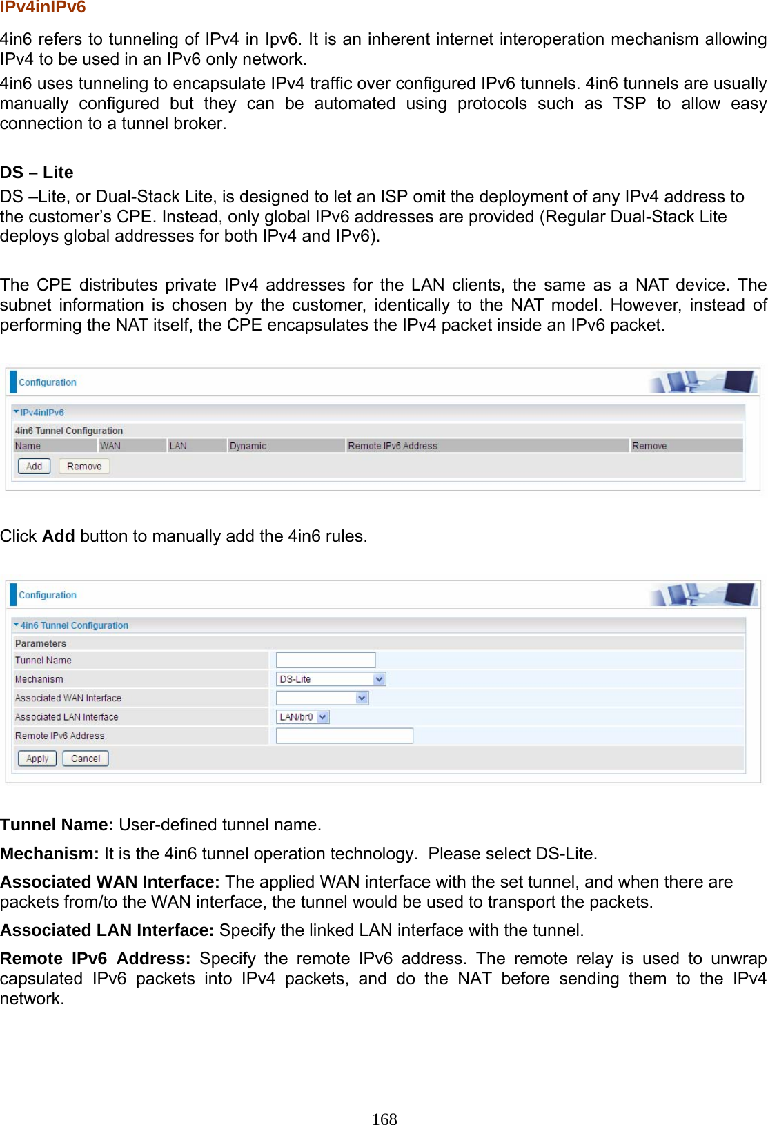
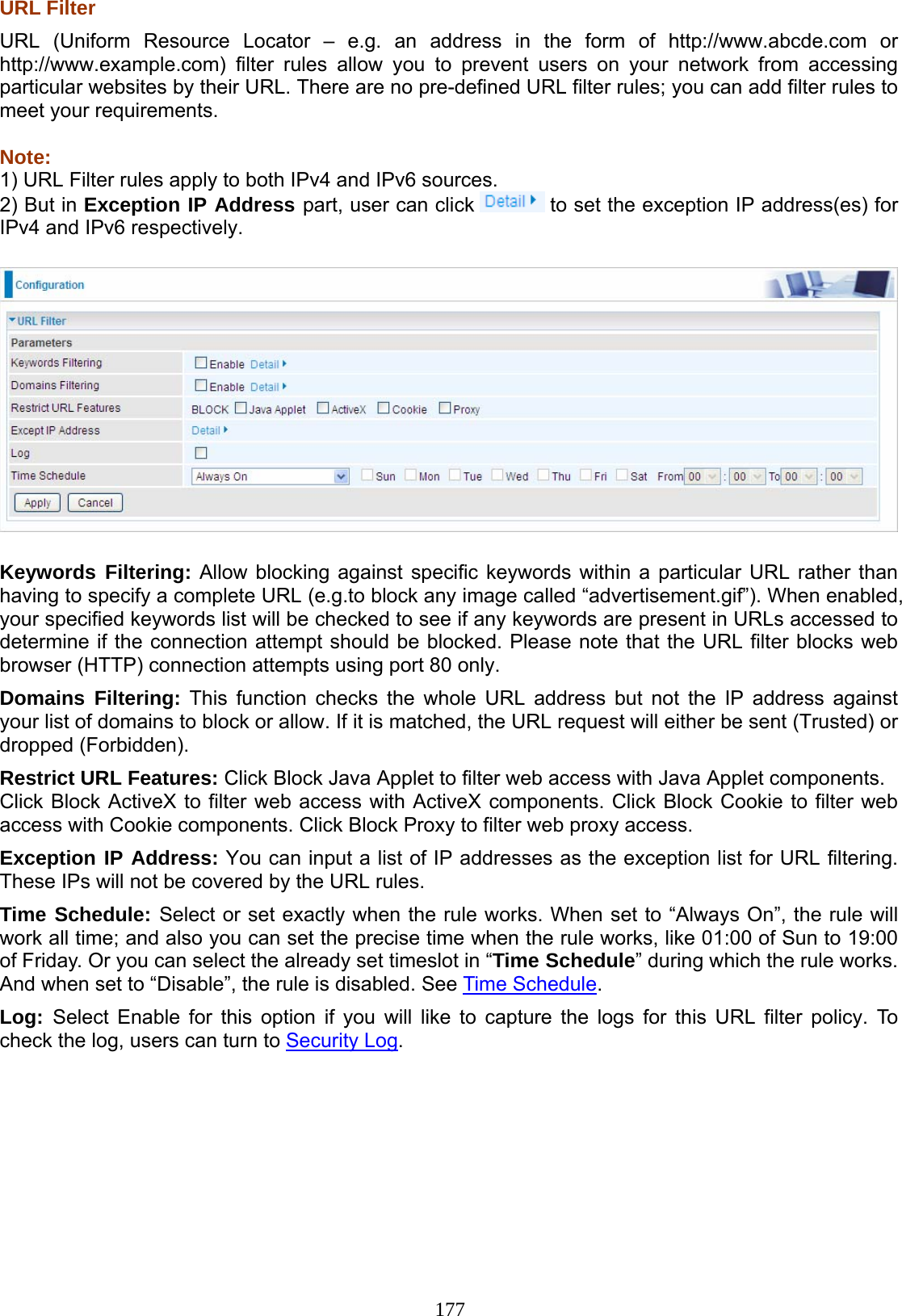
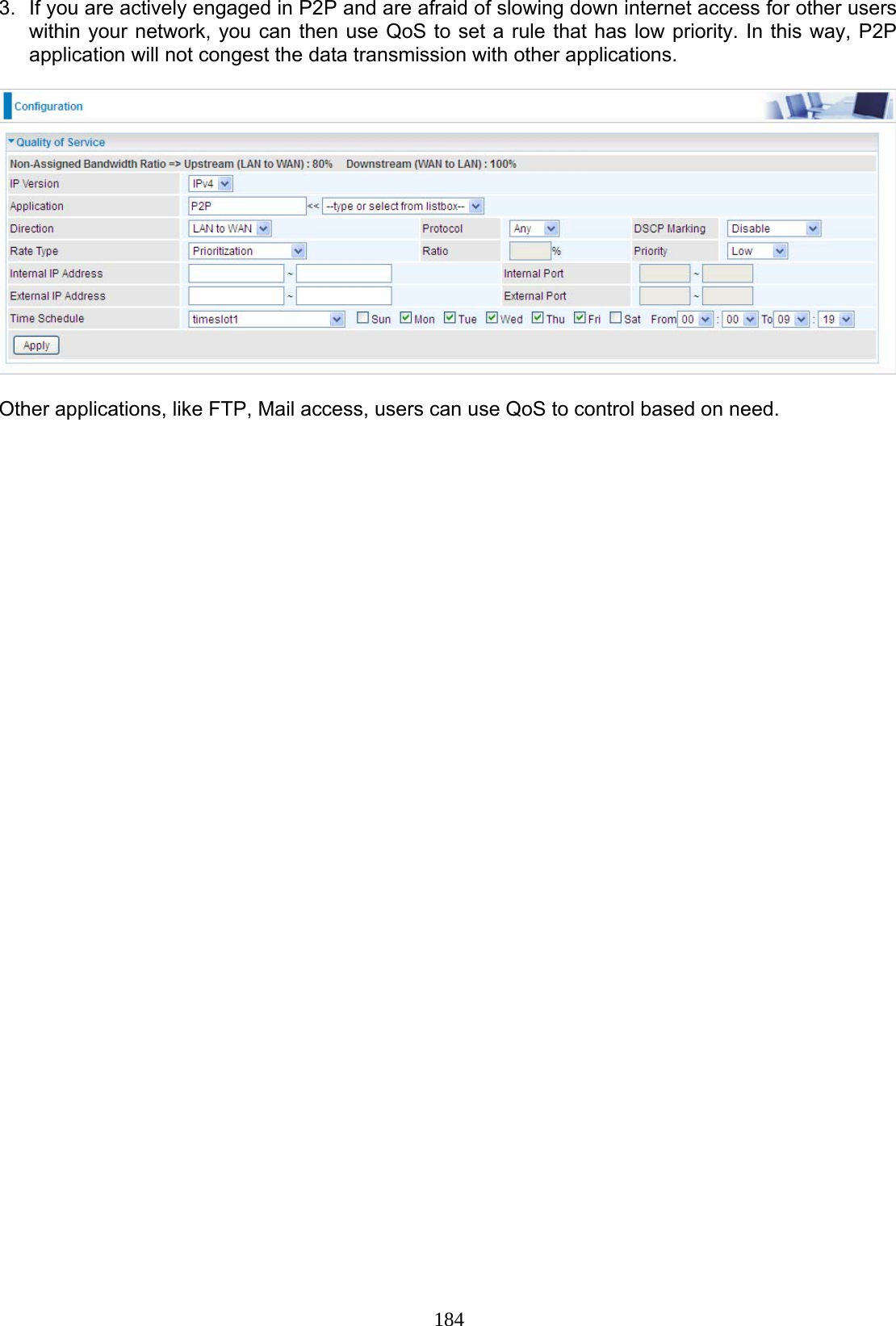
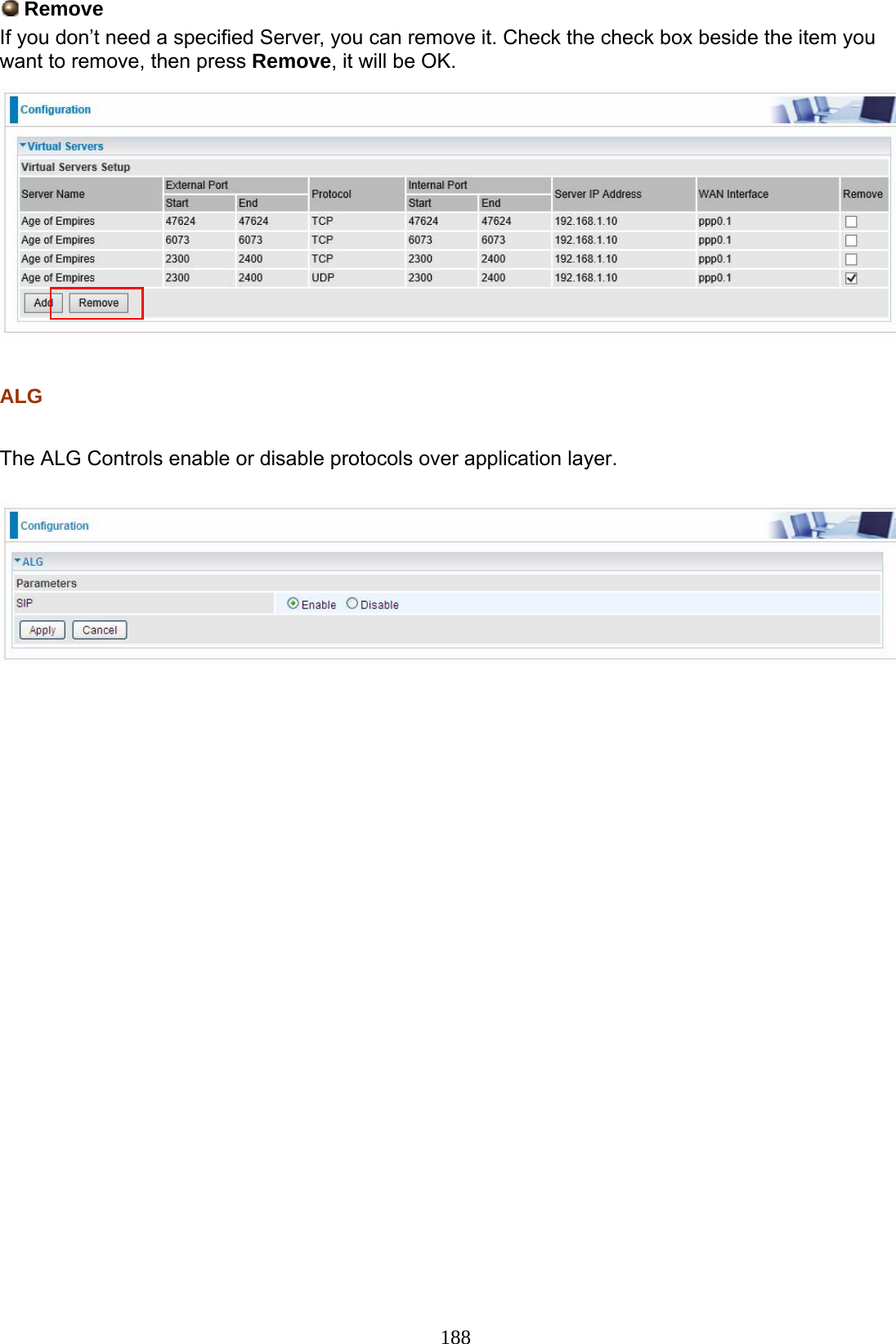
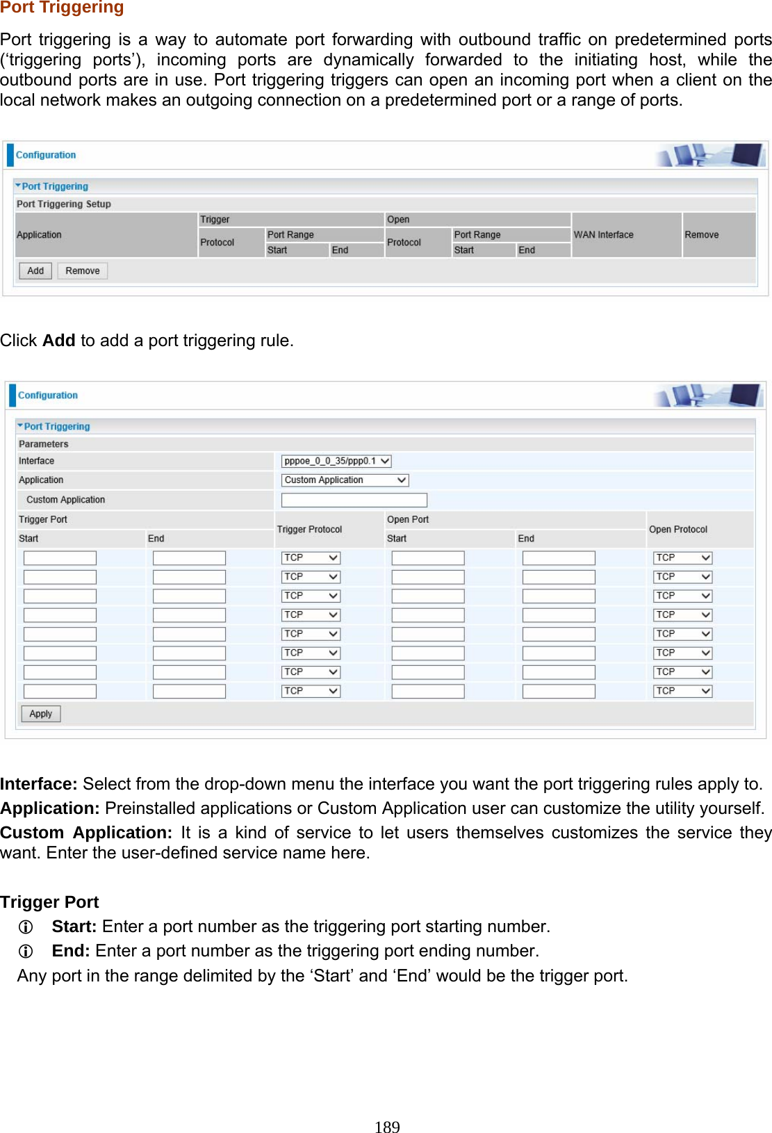
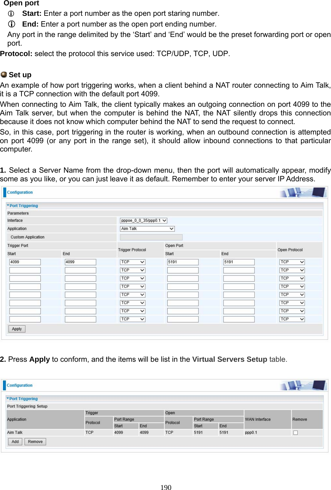
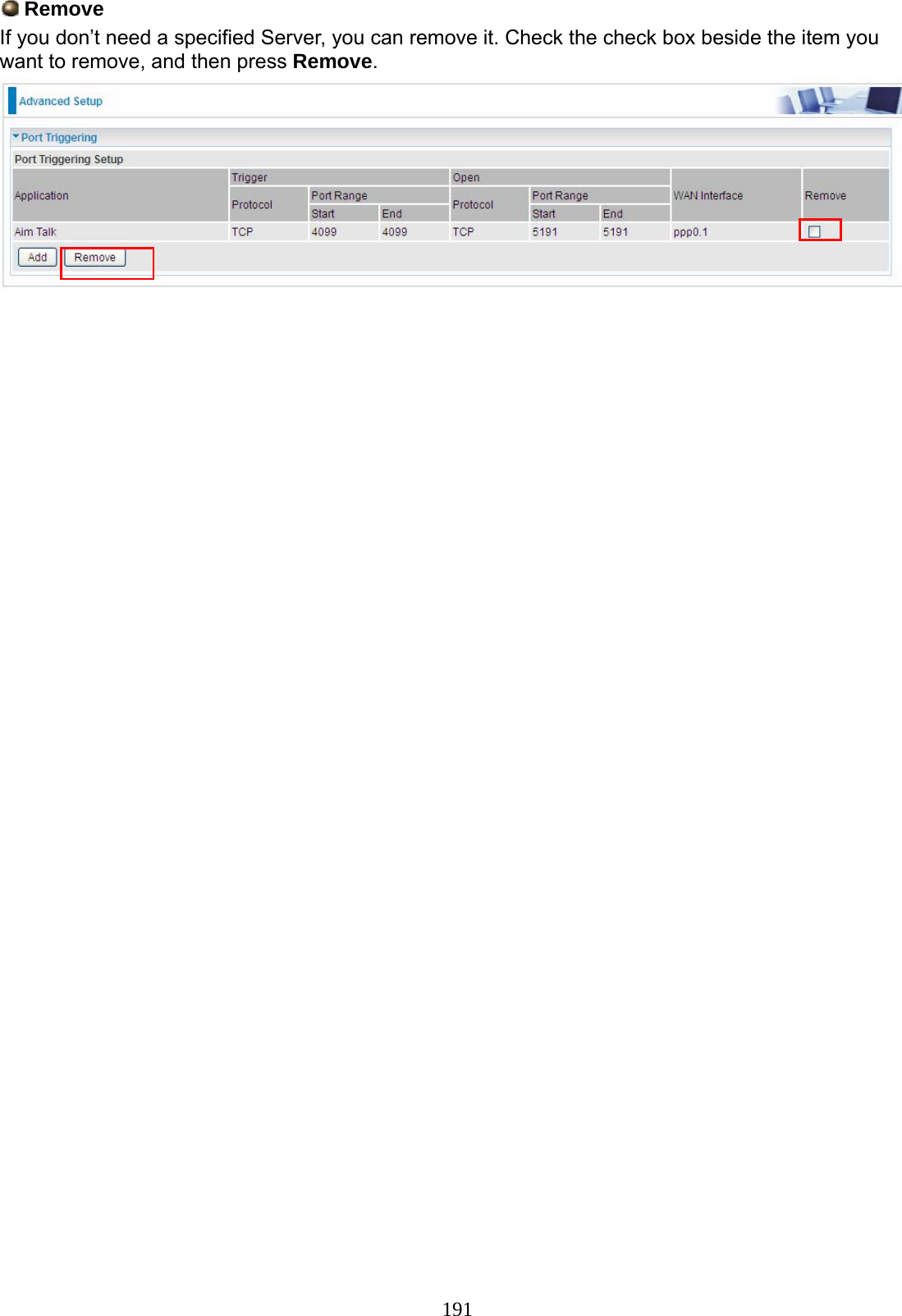
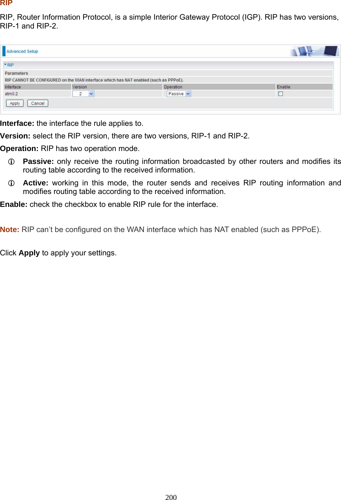
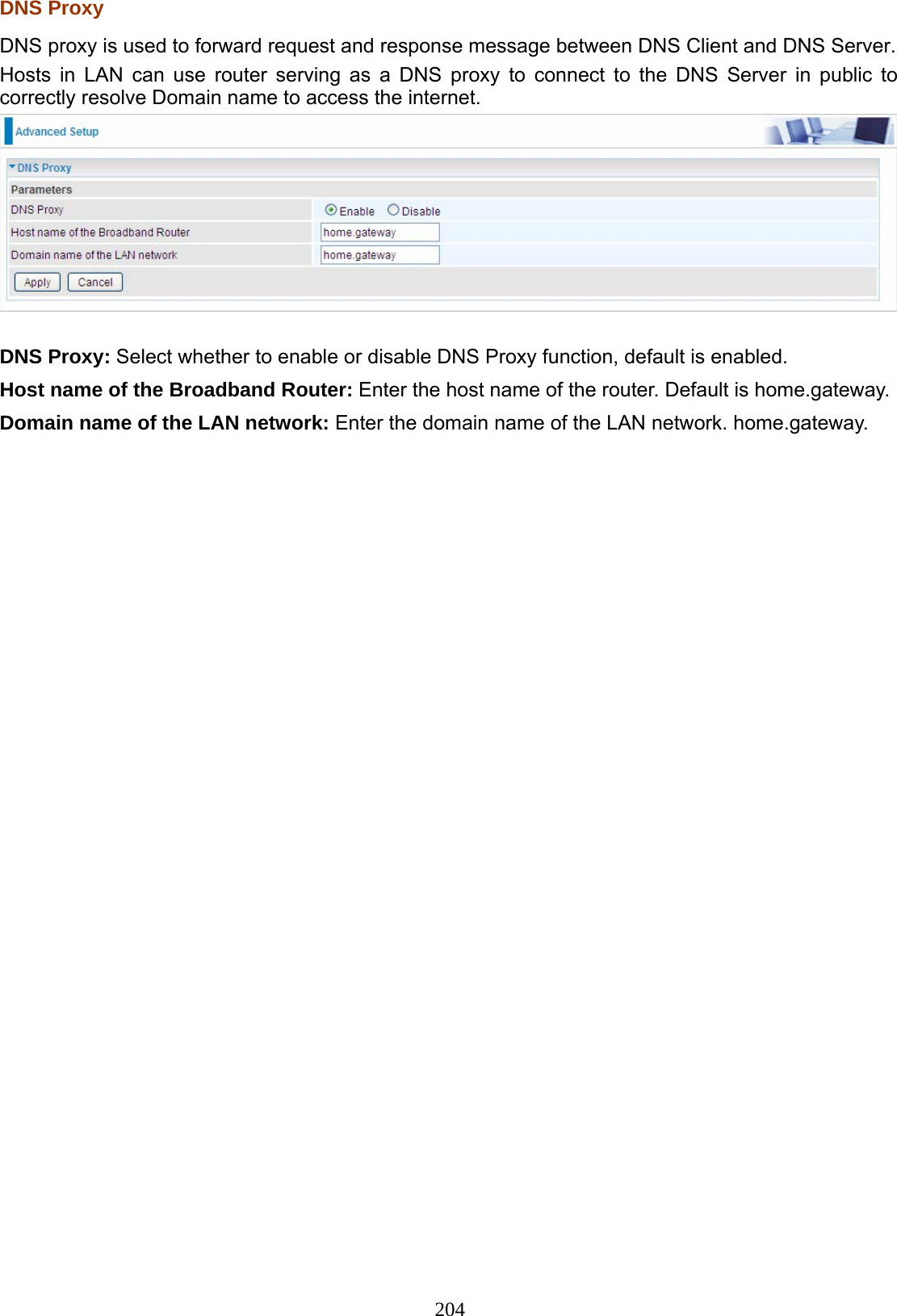
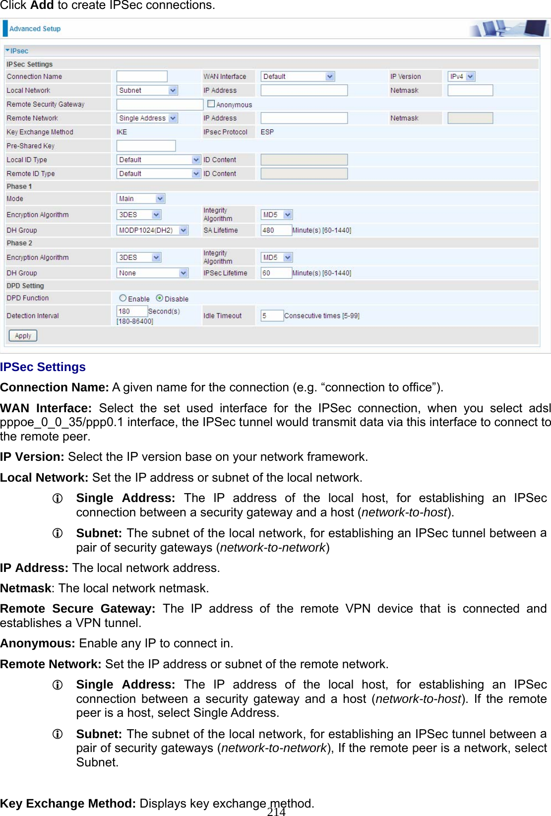
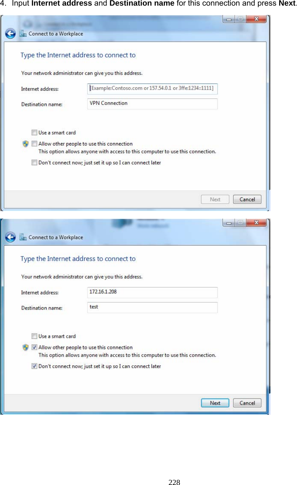
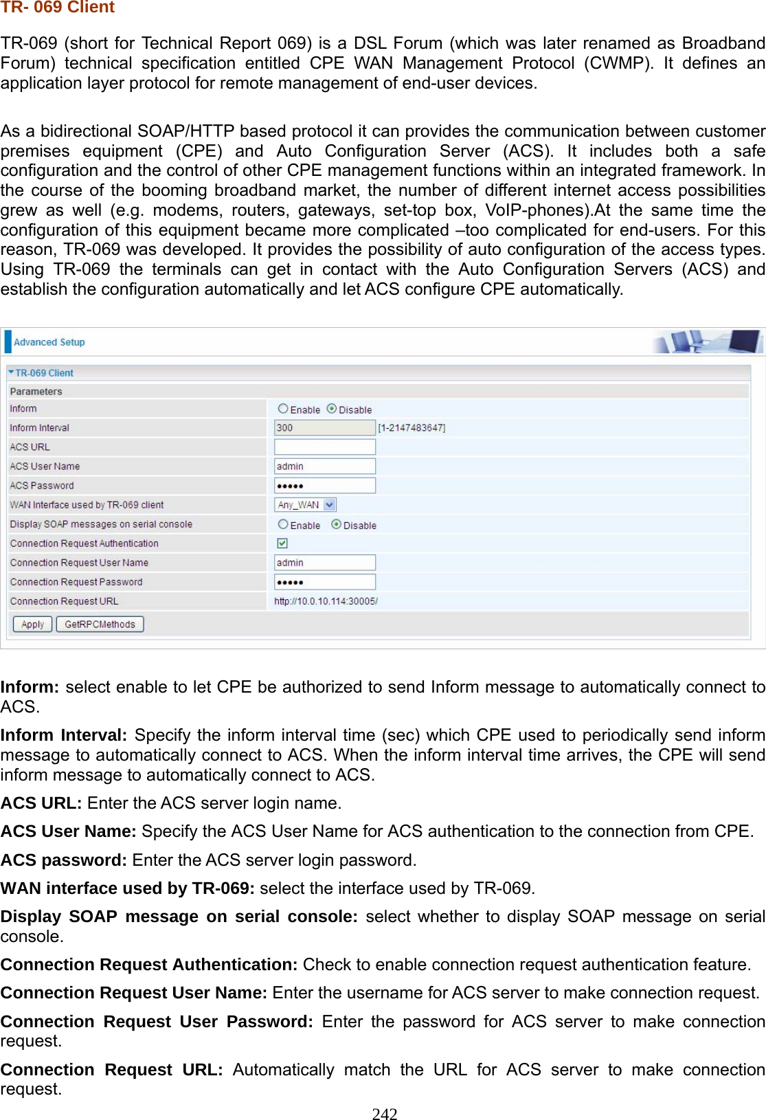
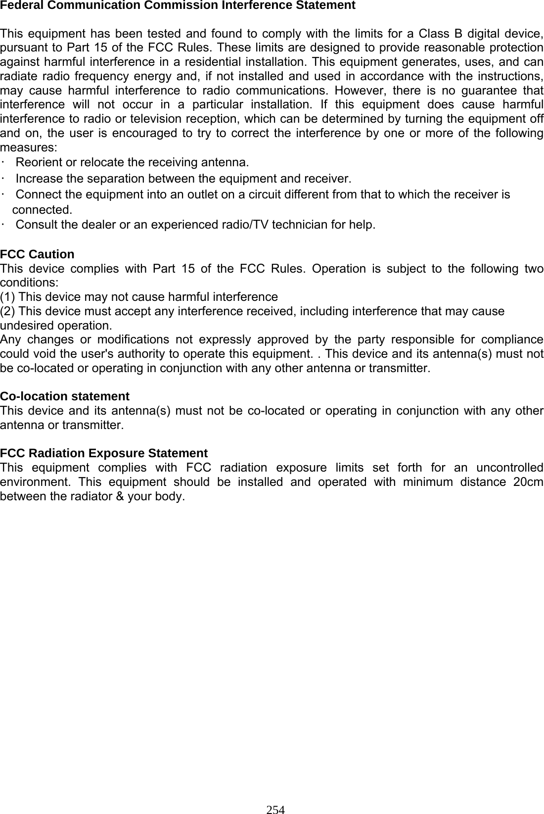
![169 Security IP Filtering Outgoing IP filtering enables you to configure your router to block specified internal/external users (IP address) from Internet access, or you can disable specific service requests (Port number) to /from Internet. The relationship among all filters is “or” operation, which means that the router checks these different filter rules one by one, starting from the first rule. As long as one of the rules is satisfied, the specified action will be taken. Outbound IP Filtering by default is set to forward all outgoing traffic from LAN to go through the router, but user can set rules to block the specific outgoing traffic. Note: The maximum number of entries: 32. Click Add button to enter the exact rule setting page. Filter Name: A user-defined rule name. User can select simply from the list box for the application for quick setup. IP Version: Select the IP Version, IPv4 or IPv6. Protocol: Set the traffic type (TCP/UDP, TCP, UDP, ICMP ) that the rule applies to. Source IP address: This is the Address-Filter used to allow or block traffic to/from particular IP address(es) featured in the IP range. If you leave empty, it means any IP address. Source Port [port or port:port]: The port or port range defines traffic from the port (specific application) or port in the set port range blocked to go through the router. Default is set port from range 1 – 65535. Destination IP address: Traffic from LAN with the particular traffic destination address specified in the IP range is to be blocked from going through the router, similarly set as the Source IP address above. Destination Port [port or port: port]: Traffic with the particular set destination port or port in the set port range is to be blocked from going through the router. Default is set port from port range: 1 – 65535.](https://usermanual.wiki/Billion-Electric/BIL-7800VNOX.user-manual-3/User-Guide-1950647-Page-23.png)
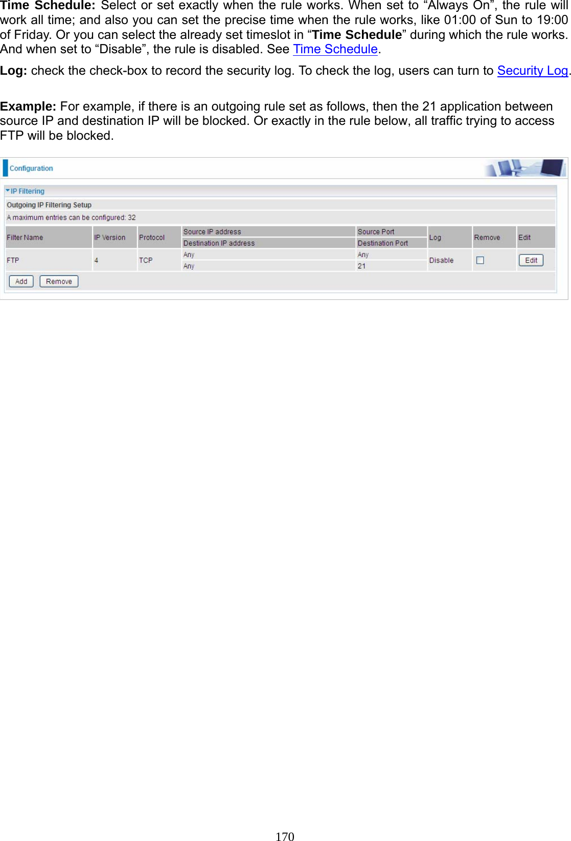
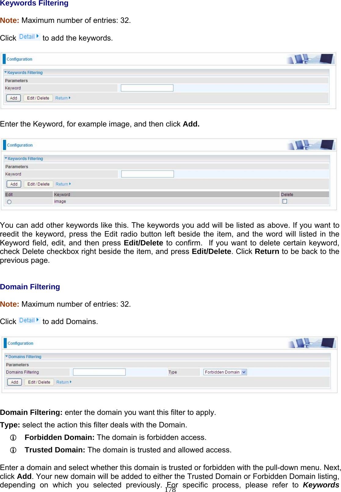
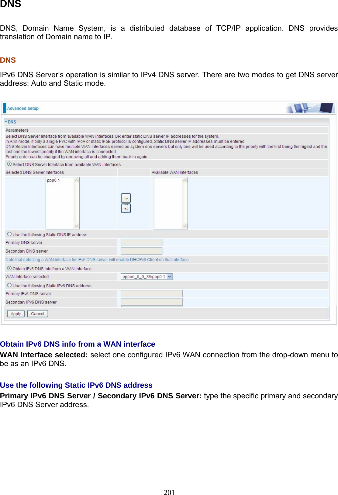
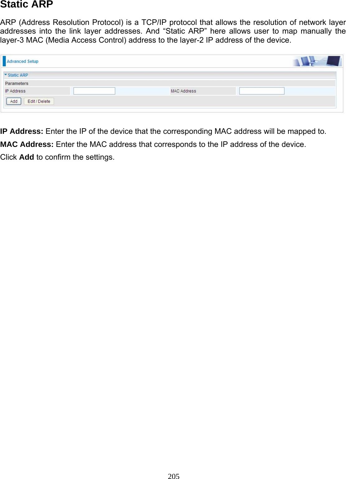
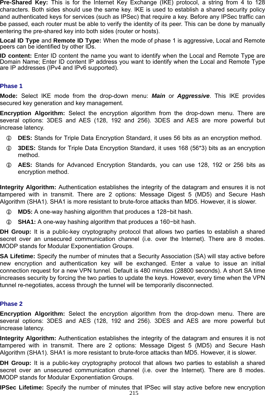
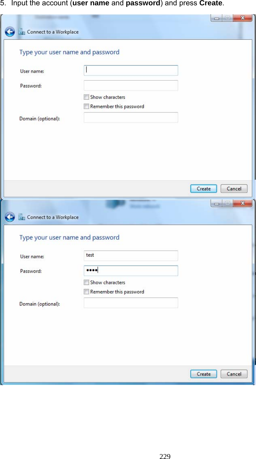
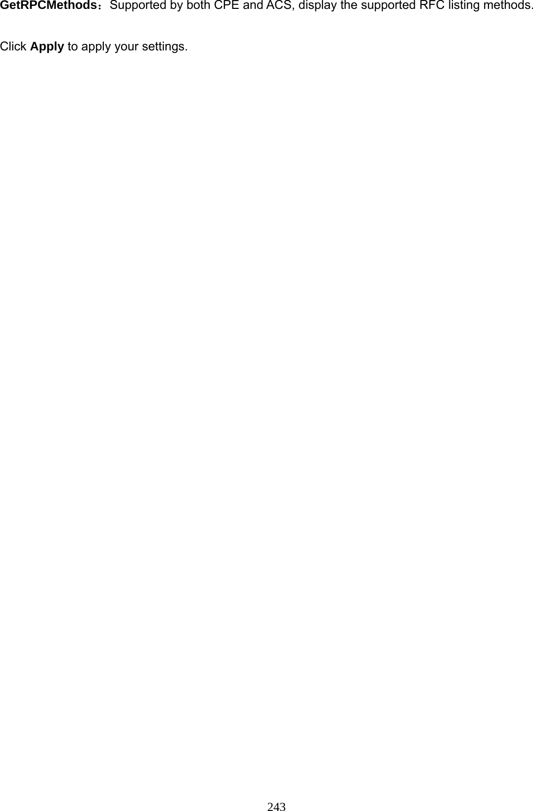
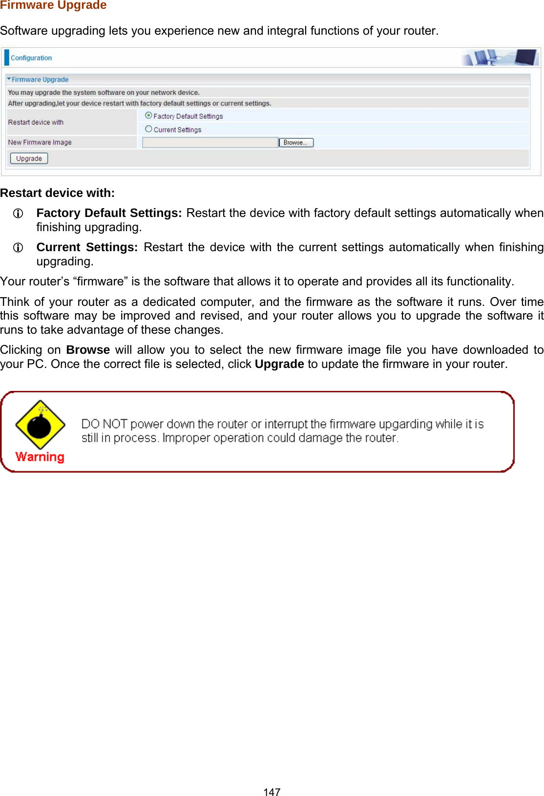
![171 IP Filtering Incoming Incoming IP Filtering is set by default to block all incoming traffic, but user can set rules to forward the specific incoming traffic. Note: 1. The maximum number of entries: 32. 2. When LAN side firewall or firewall in WAN interface(s) is enabled, user can move here to add allowing rules to pass through the firewall. Click Add button to enter the exact rule setting page. Filter Name: A user-defined rule name. User can select simply from the list box for the application for quick setup. IP Version: Select the IP Version, IPv4 or IPv6. Protocol: Set the traffic type (TCP/UDP, TCP, UDP, ICMP ) that the rule applies to. Source IP address: This is the Address-Filter used to allow or block traffic to/from particular IP address(es) featured in the IP range.. If you leave empty, it means any IP address. Source Port [port or port:port]: The port or port range defines traffic from the port (specific application) or port in the set port range blocked to go through the router. Default is set port from range 1 – 65535. Destination IP address: Traffic from LAN with the particular traffic destination address specified in the IP range is to be blocked from going through the router, similarly set as the Source IP address above. Destination Port [port or port : port]: Traffic with the particular set destination port or port in the set port range is to be blocked from going through the router. Default is set port from port range: 1 – 65535 Interfaces: Check if the filter rule applies to all interfaces. User can base on need select interfaces to make the rule take effect with those interfaces. Time Schedule: Select or set exactly when the rule works. When set to “Always On”, the rule will work all time; and also you can set the precise time when the rule works, like 01:00 of Sun to 19:00 of Friday. Or you can select the already set timeslot in “Time Schedule” during which the rule works.](https://usermanual.wiki/Billion-Electric/BIL-7800VNOX.user-manual-3/User-Guide-1950647-Page-25.png)