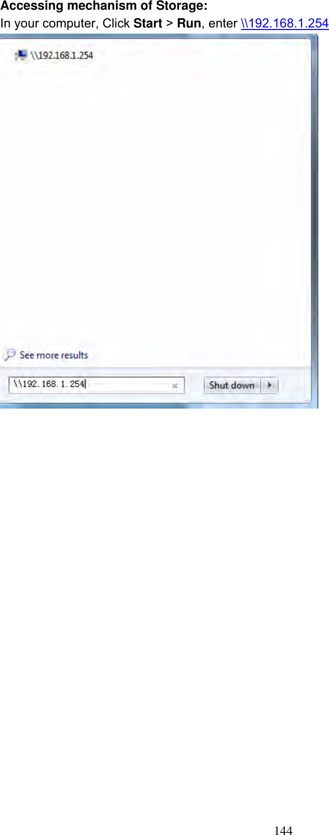
Billion Electric BIL-8700AXL Triple-WAN Wireless 1600 Mbps VPN VDSL2/ADSL2+ Firewall Router User Manual Part 1
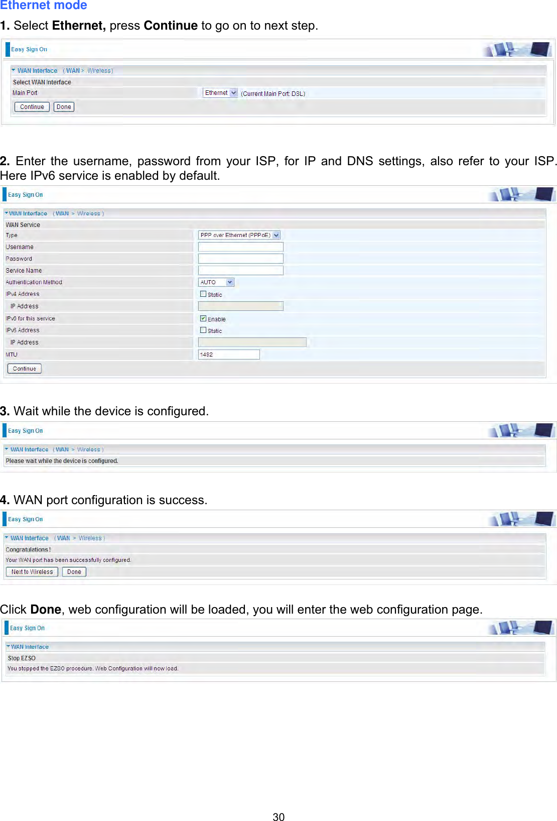
Billion Electric Co., Ltd. Triple-WAN Wireless 1600 Mbps VPN VDSL2/ADSL2+ Firewall Router Part 1
Contents
- 1. User Manual Part 1
- 2. User Manual Part 2
User Manual Part 1
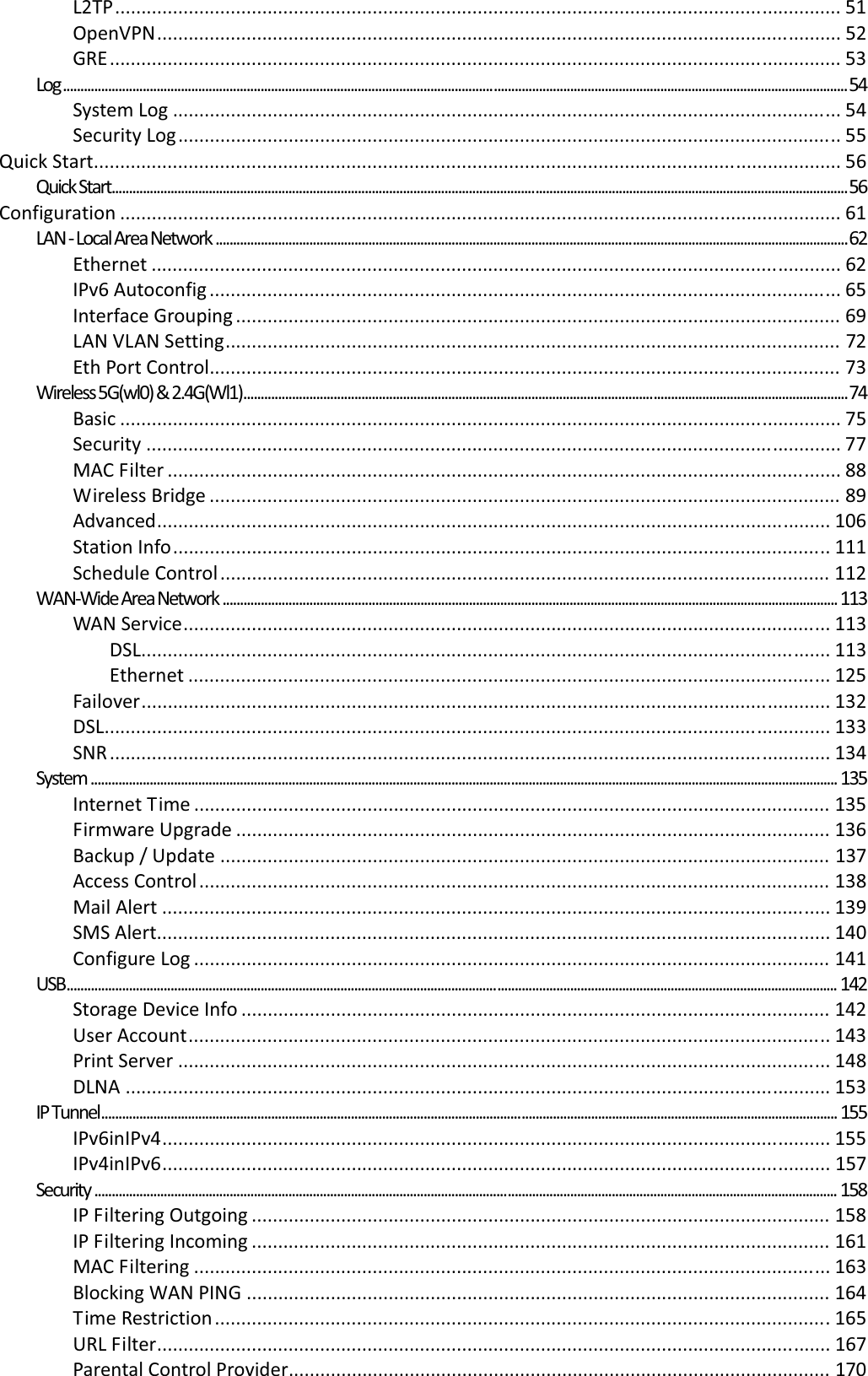
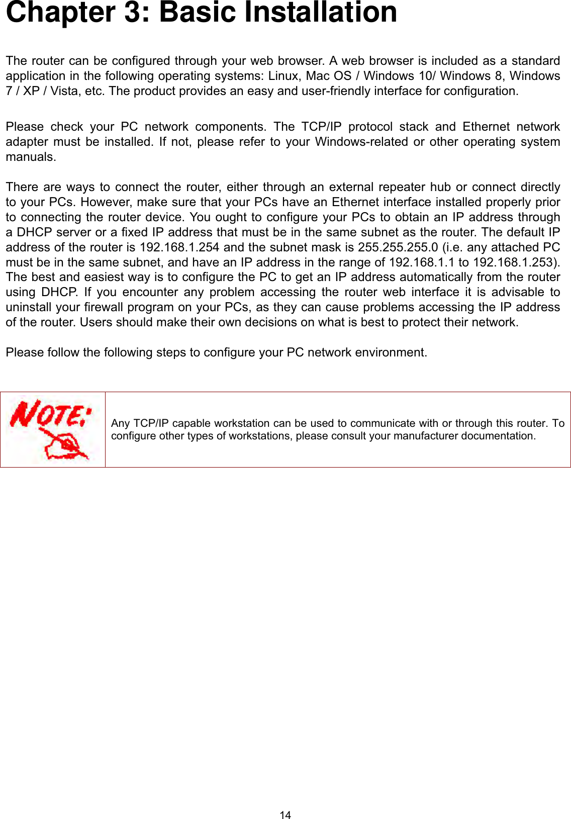
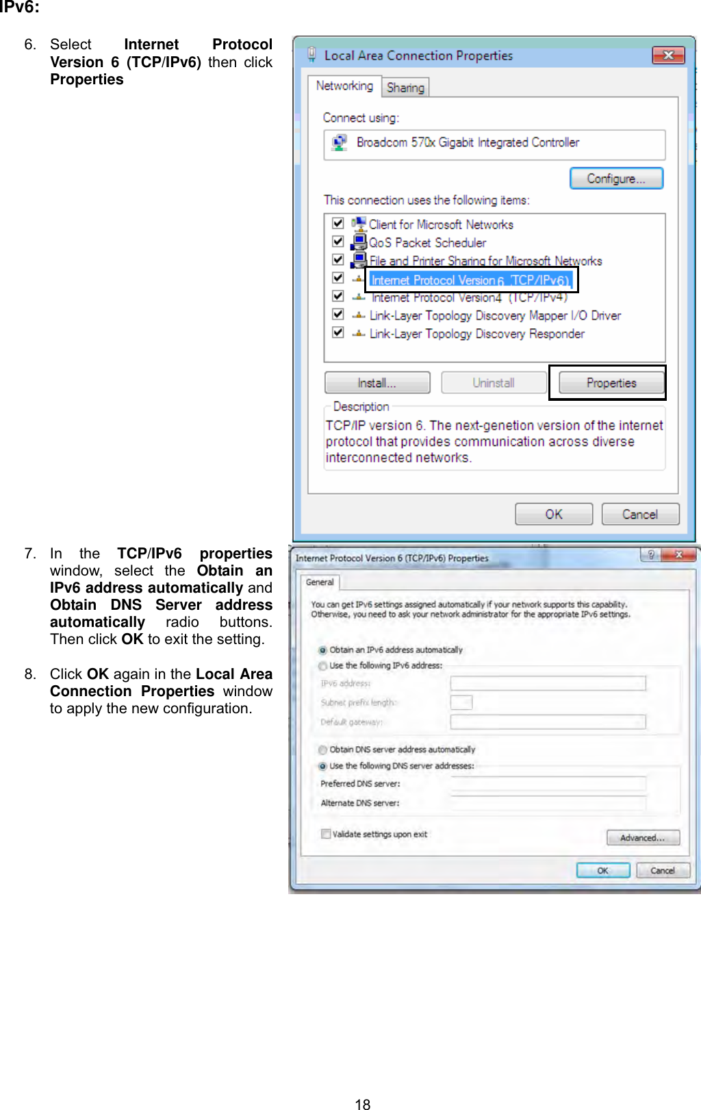
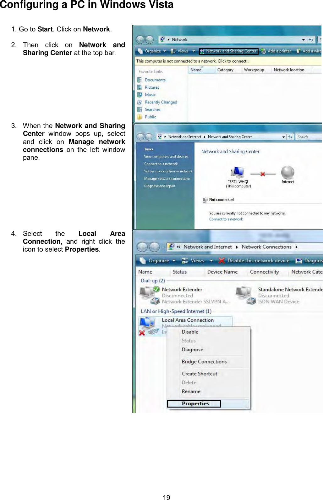
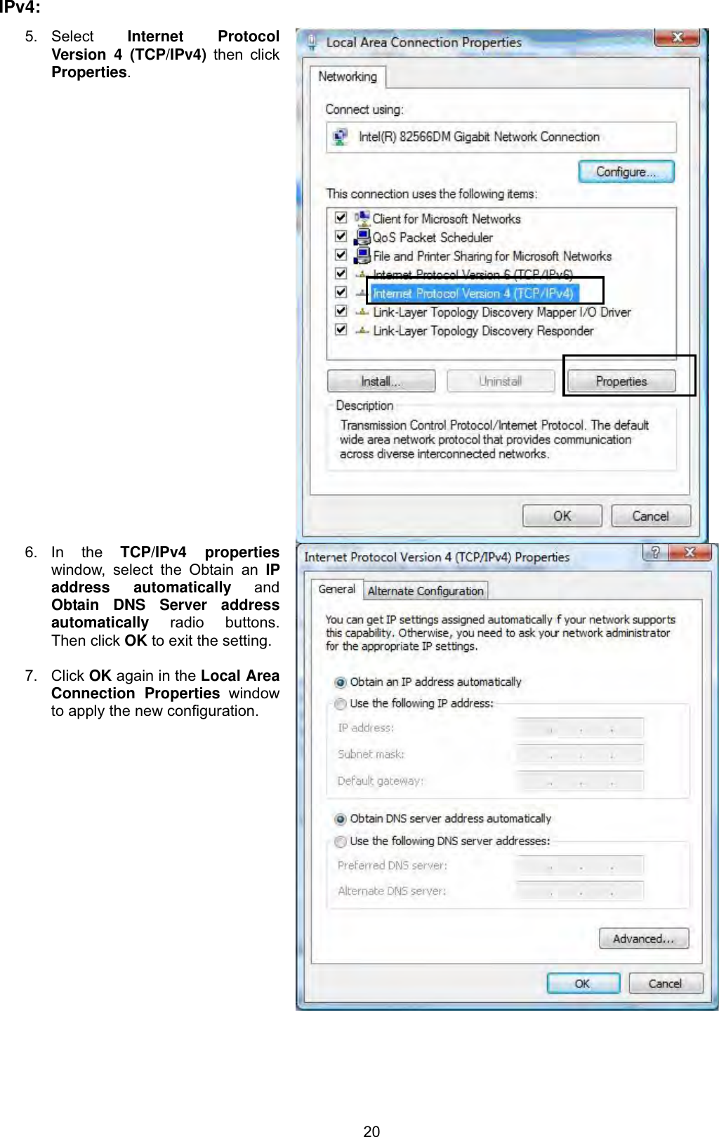
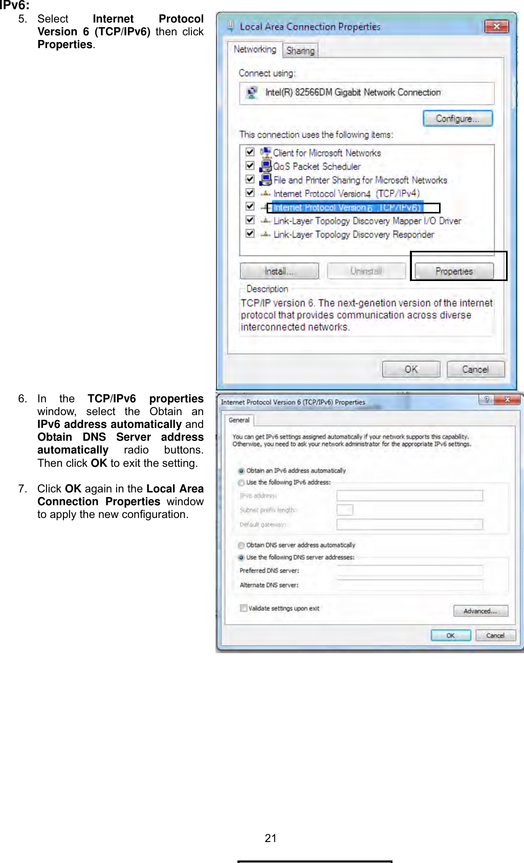
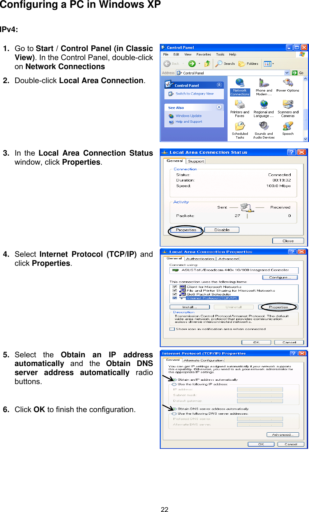

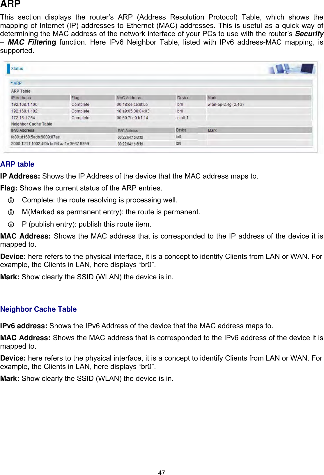

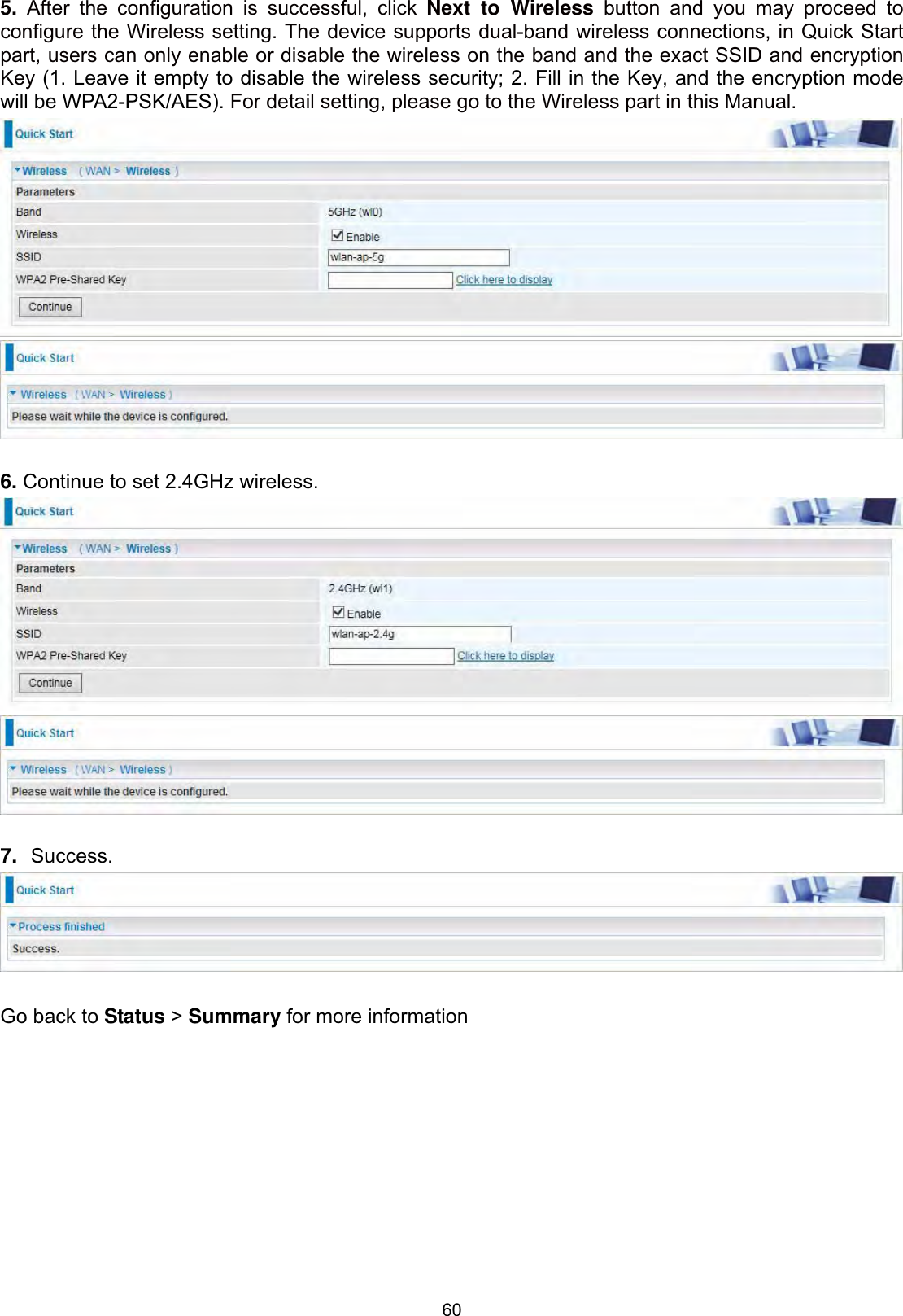
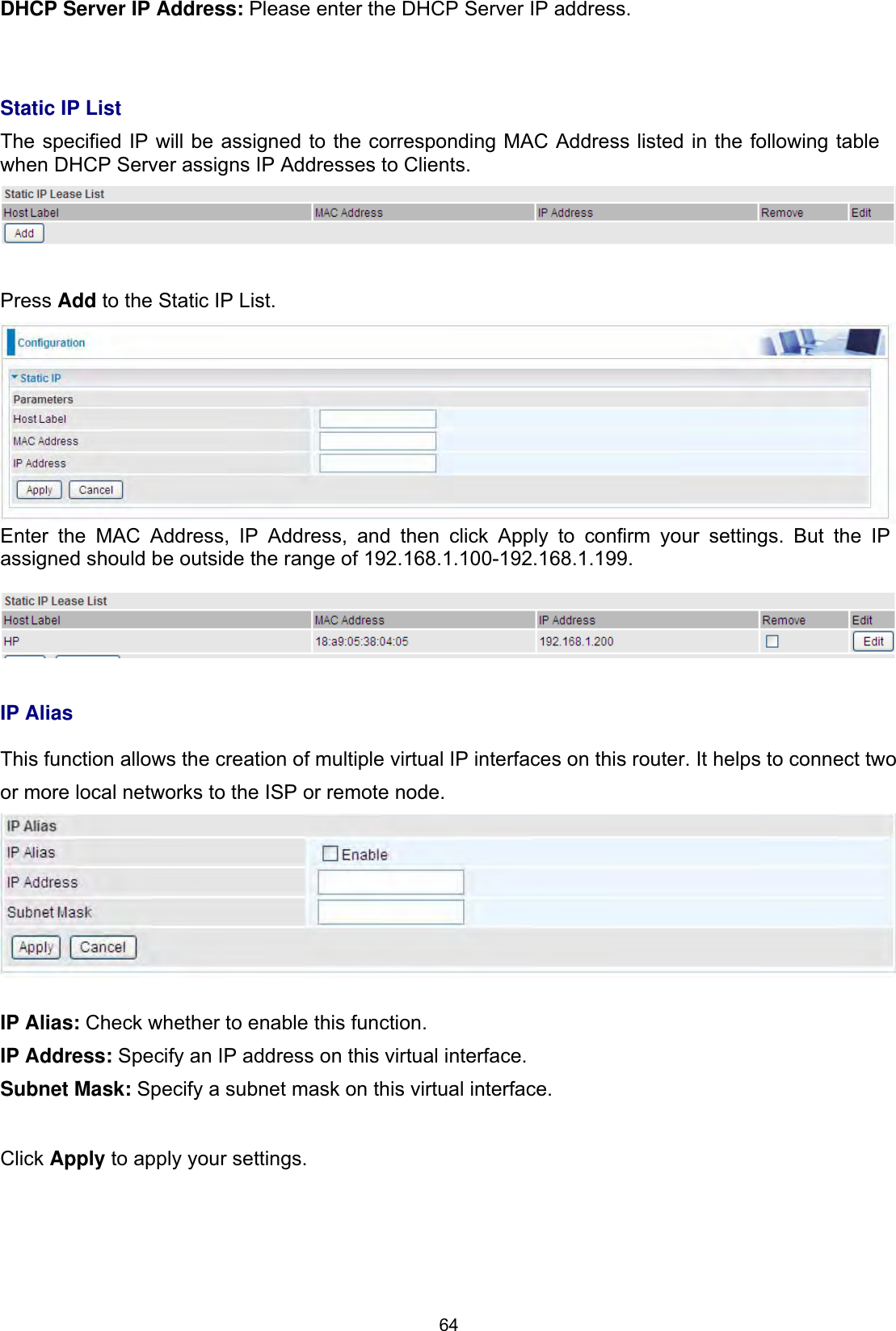
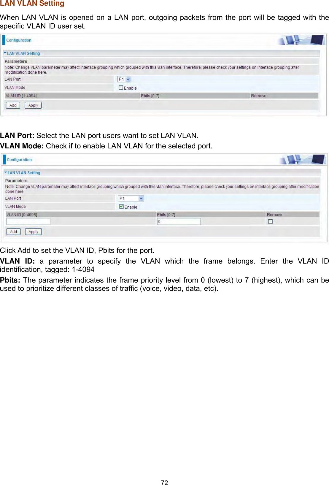
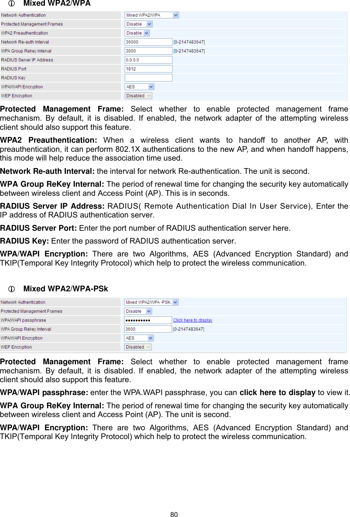
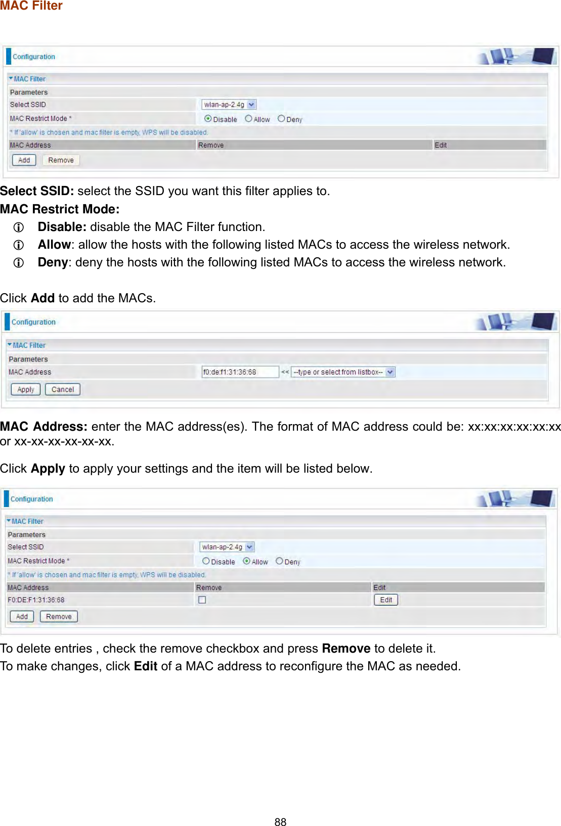


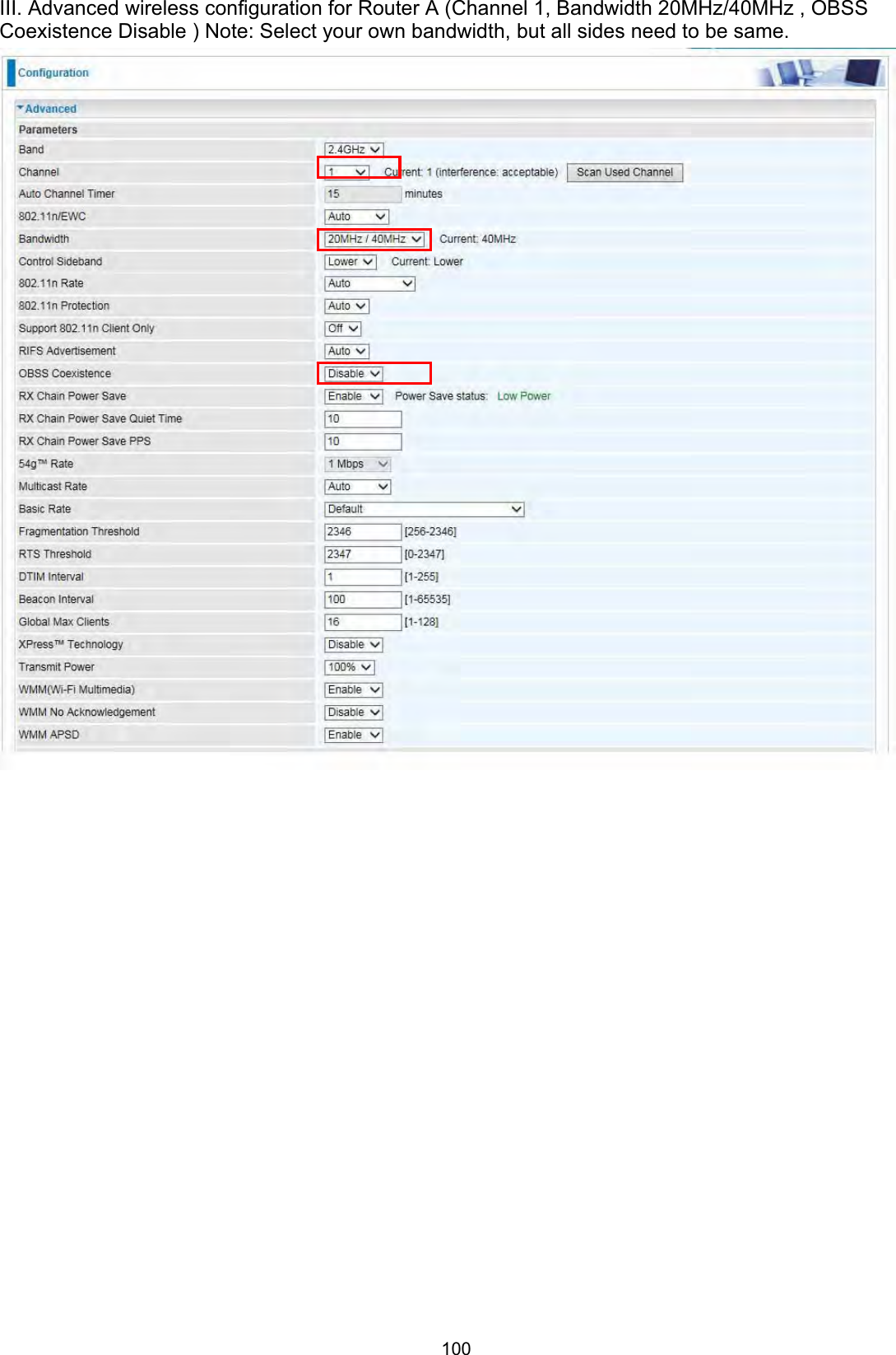
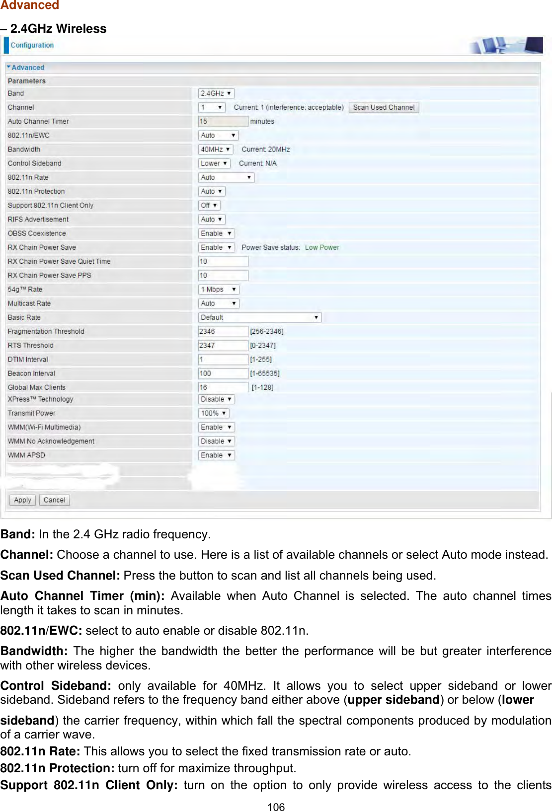
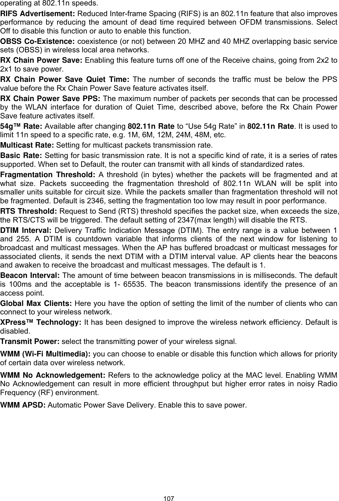
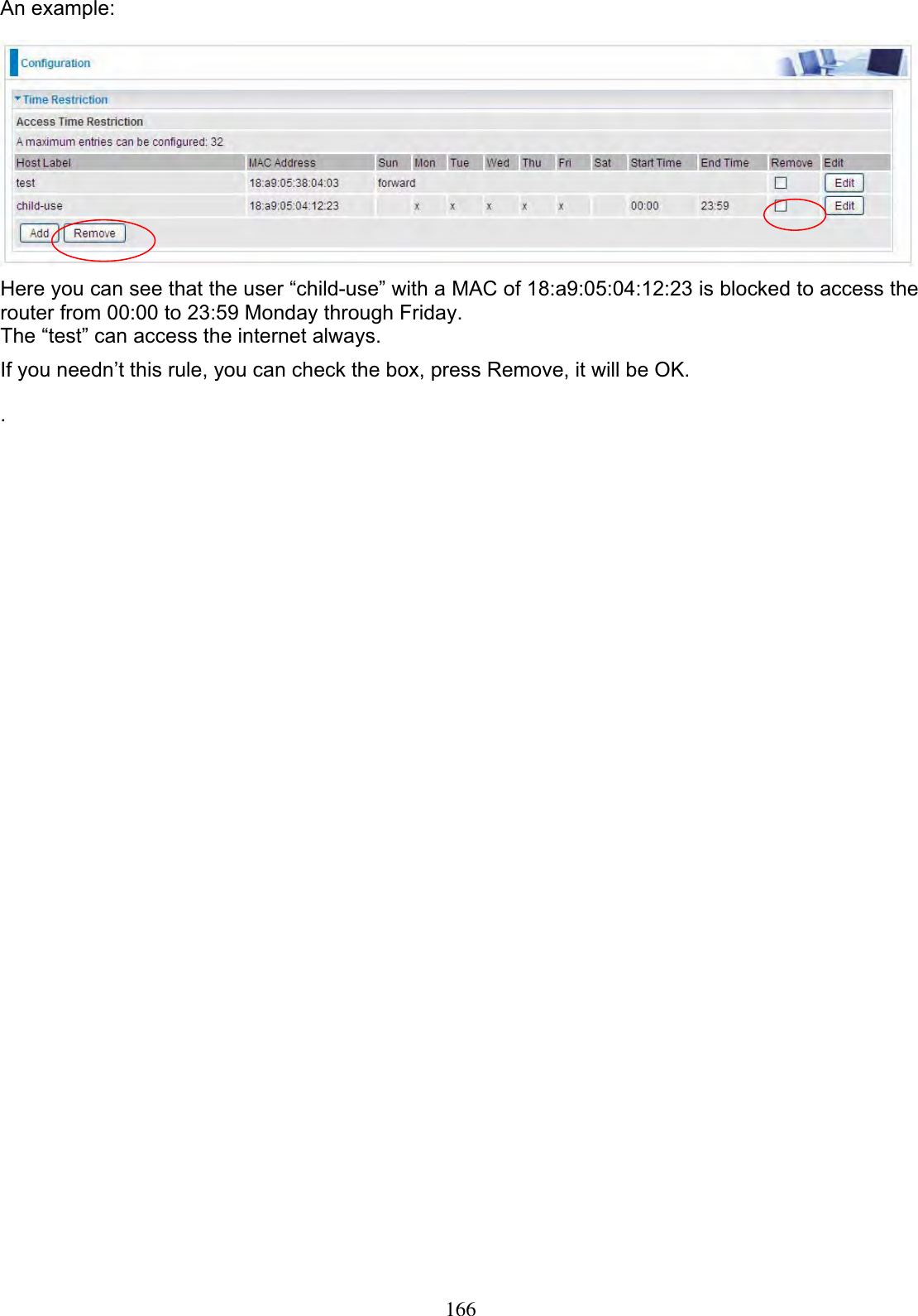
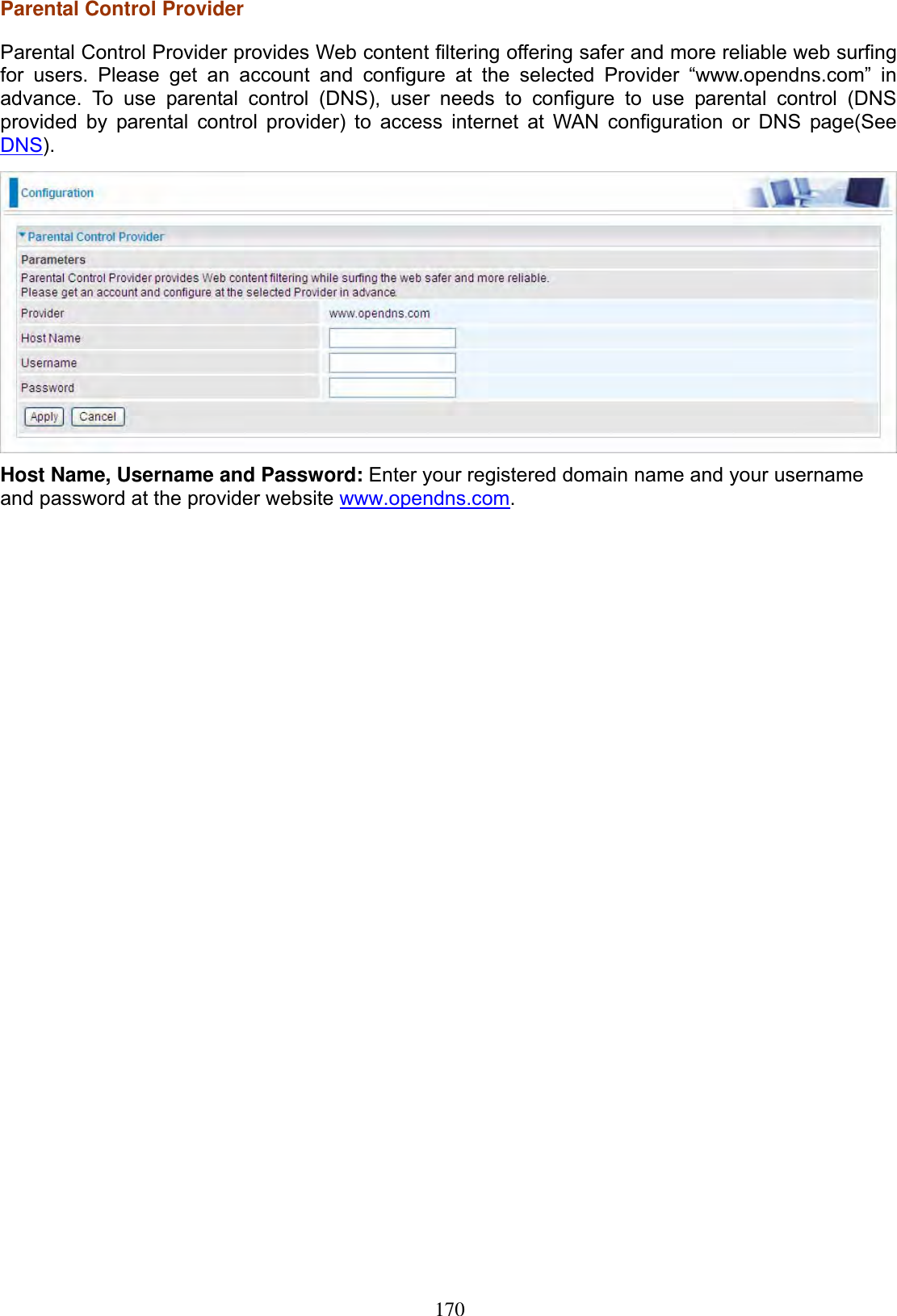
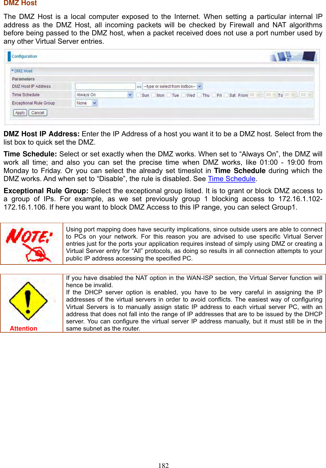
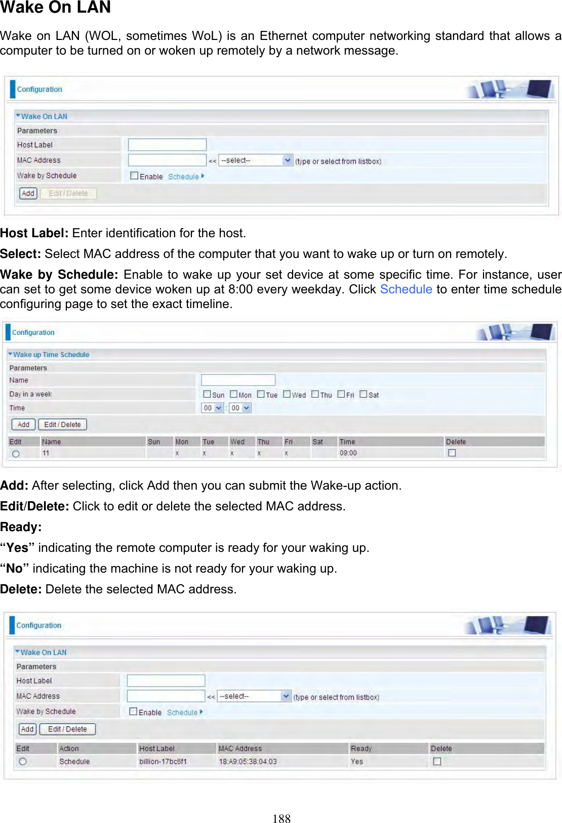
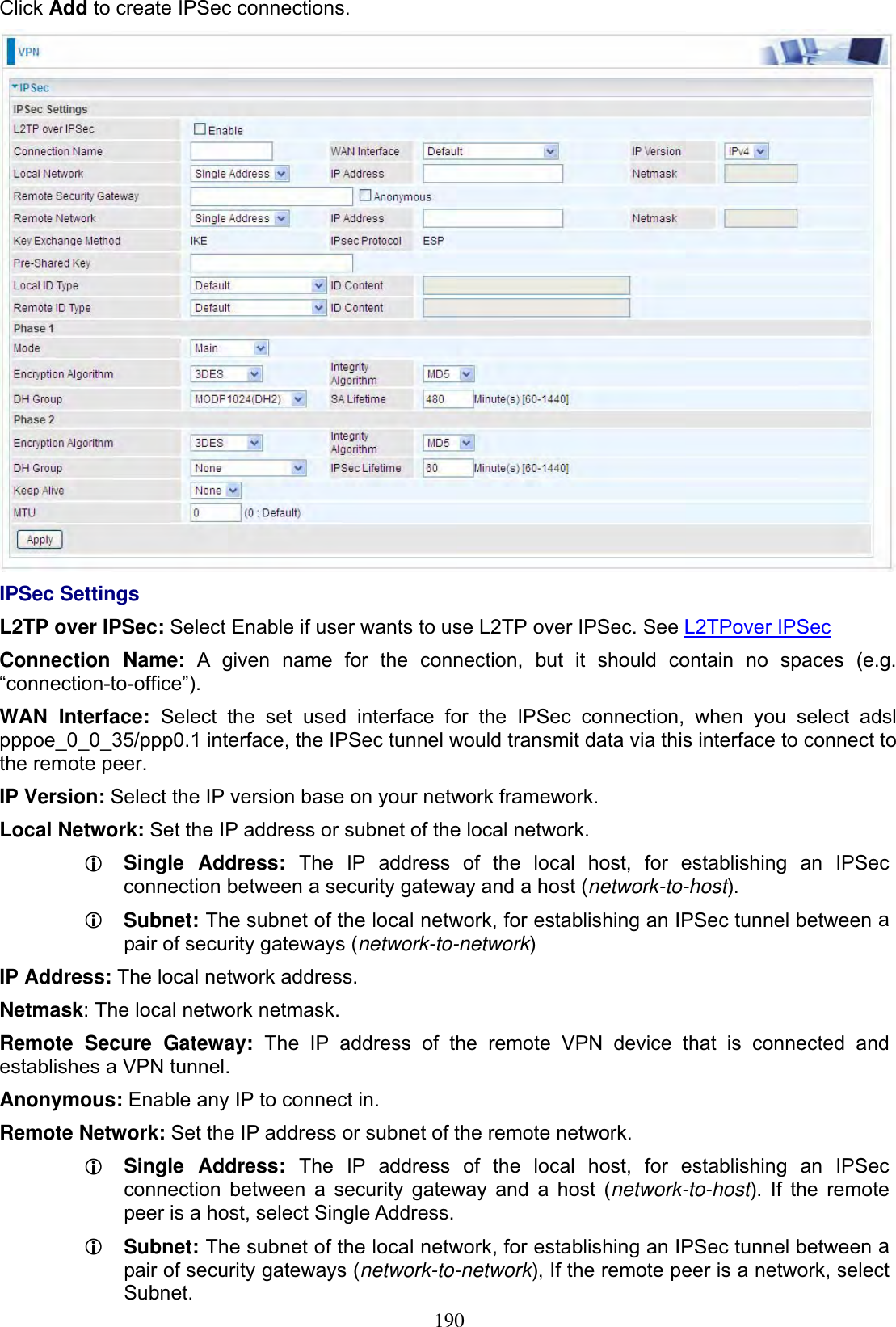
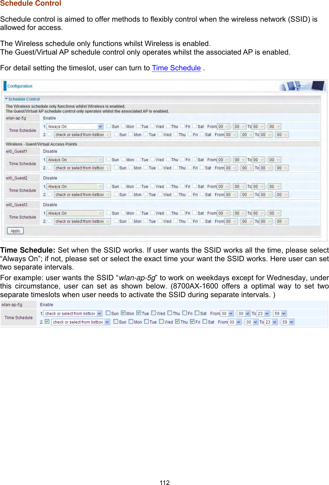
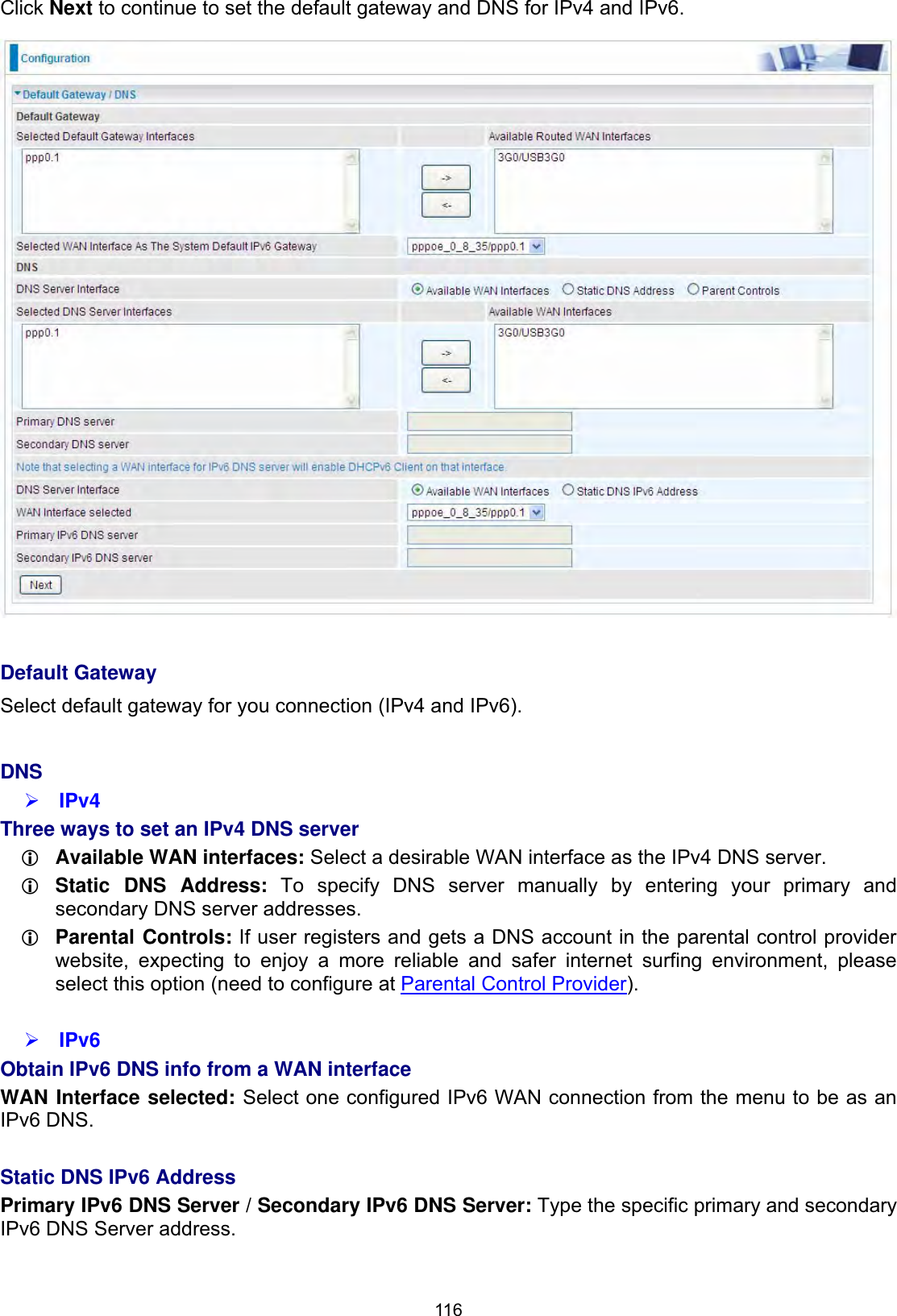
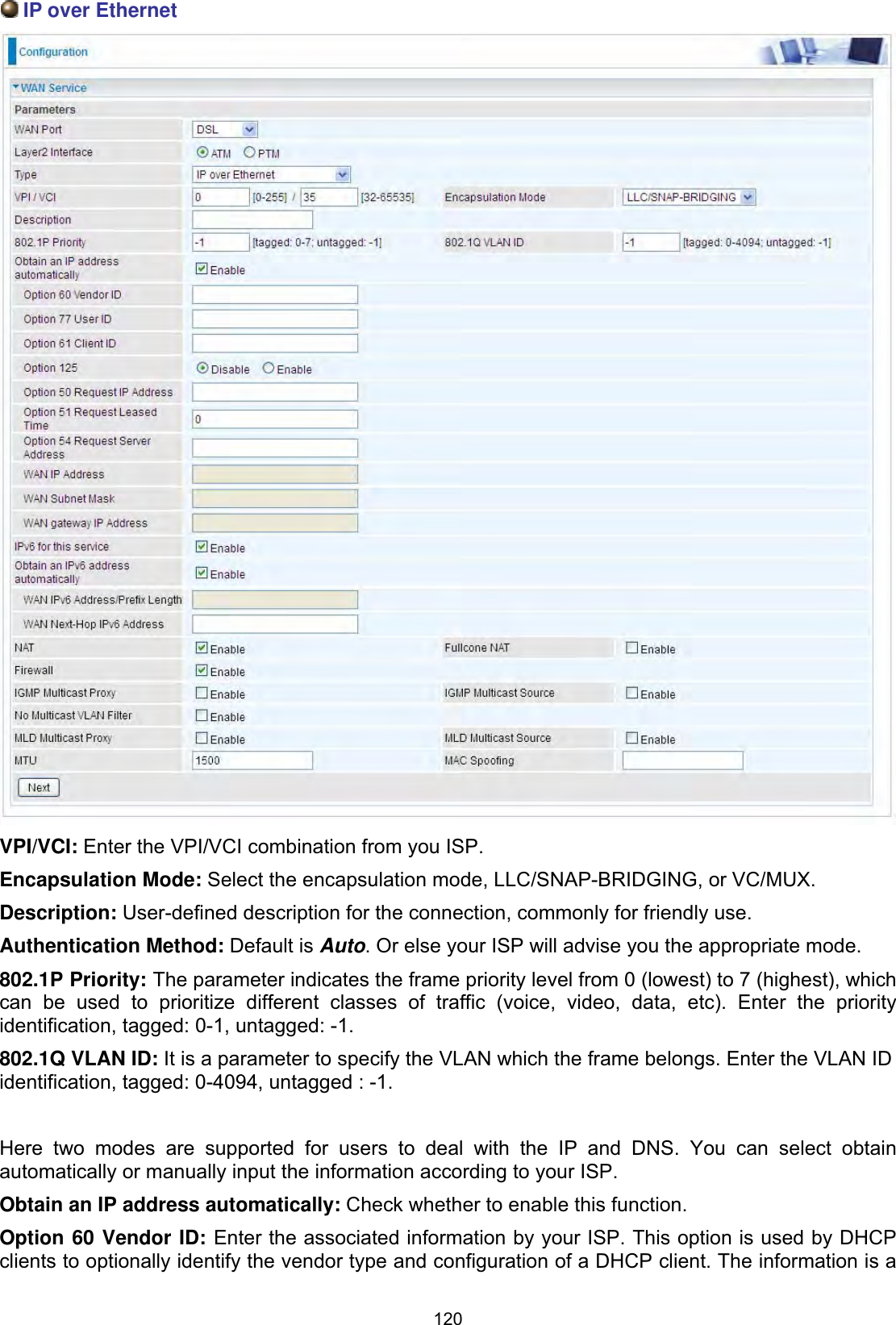
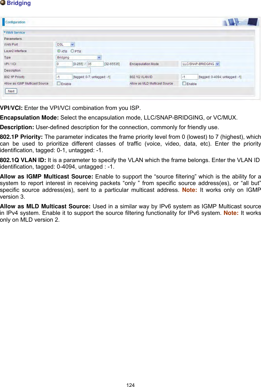
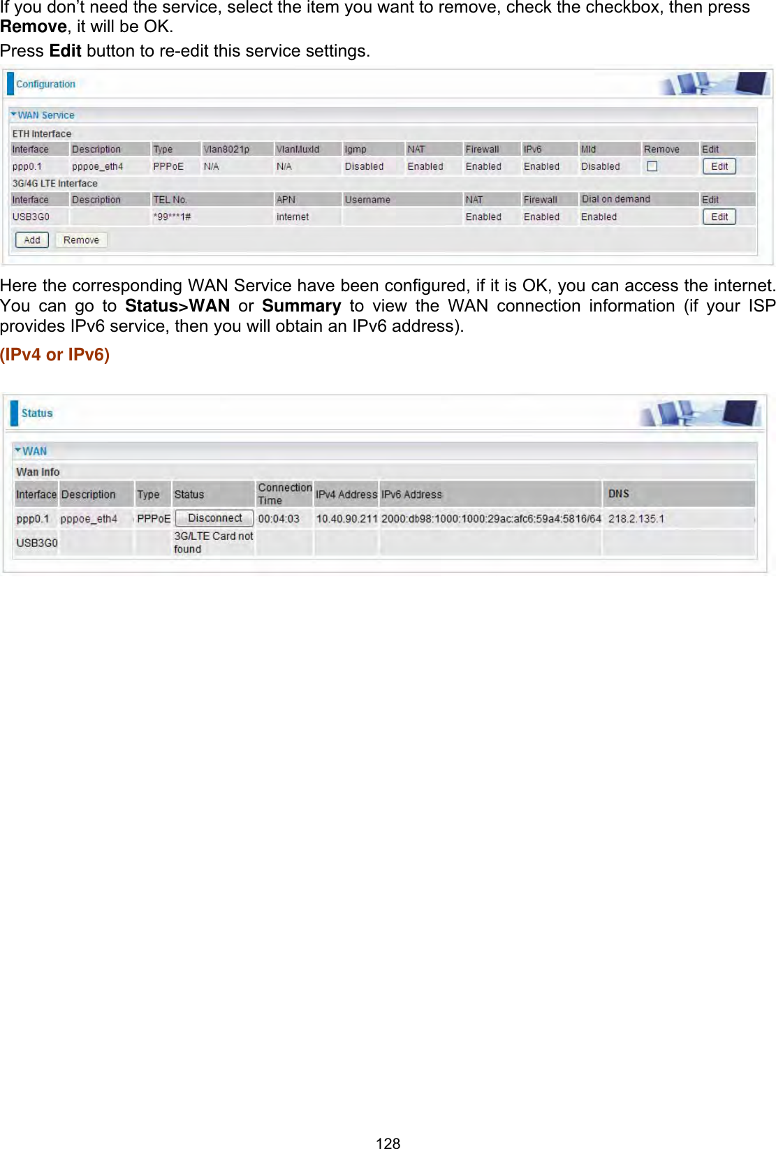
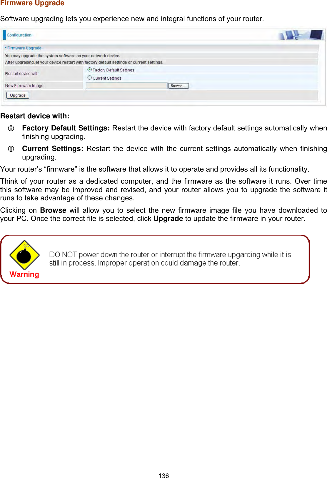
![109802.11n Rate: This allows you to select the fixed transmission rate or auto.802.11n Protection: turn off for maximize throughput. Support 802.11n Client Only: turn on the option to only provide wireless access to the clients operating at 802.11n speeds.RIFS Advertisement: Reduced Inter-frame Spacing (RIFS) is an 802.11n feature that also improves performance by reducing the amount of dead time required between OFDM transmissions. Select Off to disable this function or auto to enable this function.OBSS Co-Existence: coexistence (or not) between 20 MHZ and 40 MHZ overlapping basic service sets (OBSS) in wireless local area networks. RX Chain Power Save: Enabling this feature turns off one of the Receive chains, going from 2x2 to 2x1 to save power.RX Chain Power Save Quiet Time: The number of seconds the traffic must be below the PPS value before the Rx Chain Power Save feature activates itself.RX Chain Power Save PPS: The maximum number of packets per seconds that can be processed by the WLAN interface for duration of Quiet Time, described above, before the Rx Chain Power Save feature activates itself.54g™ Rate: Available after changing 802.11n Rate to “Use 54g Rate” in 802.11n Rate. It is used to limit 11n speed to a specific rate, e.g. 6M, 12M, 24M, 48, etc.Multicast Rate: Setting for multicast packets transmission rate. Basic Rate: Setting for basic transmission rate. It is not a specific kind of rate but a series of rates supported. When set to Default, the router can transmit with all kinds of standardized rates. Fragmentation Threshold: A threshold (in bytes) whether the packets will be fragmented and at what size. Packets succeeding the fragmentation threshold of 802.11n WLAN will be split into smaller units suitable for circuit size. While the packets smaller than fragmentation threshold will not be fragmented. Default is 2346, setting the fragmentation too low may result in poor performance.RTS Threshold: Request to Send (RTS) threshold specifies the packet size, when exceeds the size, the RTS/CTS will be triggered. The default setting of 2347(max length) will disable the RTS. DTIM Interval: Delivery Traffic Indication Message (DTIM). The entry range is a value between 1 and 255. A DTIM is countdown variable that informs clients of the next window for listening to broadcast and multicast messages. When the AP has buffered broadcast or multicast messages for associated clients, it sends the next DTIM with a DTIM interval value. AP clients hear the beacons and awaken to receive the broadcast and multicast messages. The default is 1.Beacon Interval: The amount of time between beacon transmissions in is milliseconds. The default is 100ms and the acceptable is 1- 65535. The beacon transmissions identify the presence of an access point.Global Max Clients: Here you have the option of setting the limit of the number of clients who can connect to your wireless network.XPress™ Technology: It has been designed to improve the wireless network efficiency. Default is disabled.Regulatory Mode: Select to deny any regulatory mode, which is only for 5GHz band wireless. There are two regulatory modes: Configuring Your Router Wireless 5G(wl0) & 2.4G(wl1) – Advanced for 5G Wireless ǂ802.11h: The standard solves interference problems with e.g. satellites and radar using the same 5 GHz band as 802.11a or 802.11n dual-band access points.ǂ802.11d: This standard automatically adjusts its allowed frequencies, power levels and bandwidth accordingly to the country it's located in. Pre-Network Radar Check (Used for 802.11h only): Specifies a period of time in seconds [0-99] to](https://usermanual.wiki/Billion-Electric/BIL-8700AXL.User-Manual-Part-1/User-Guide-3810626-Page-114.png)
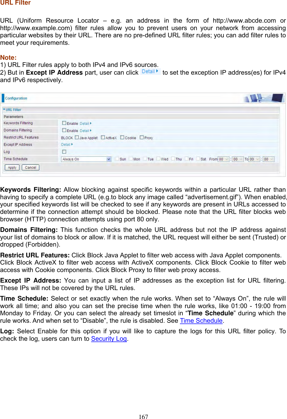
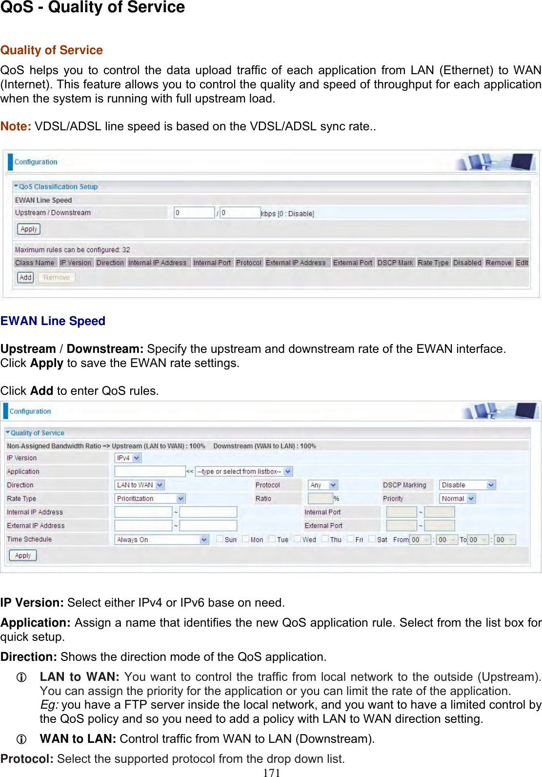
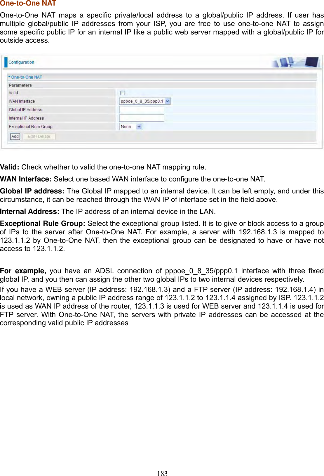
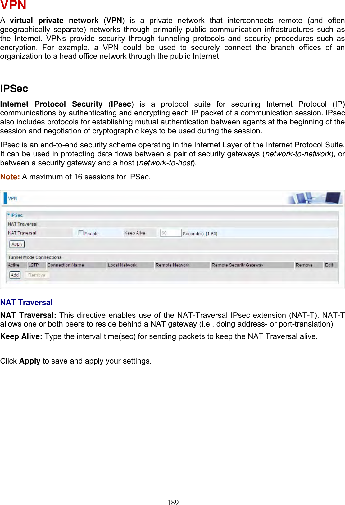
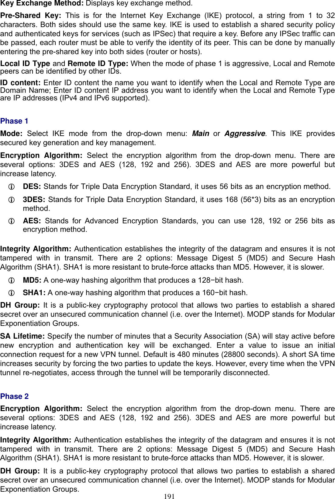
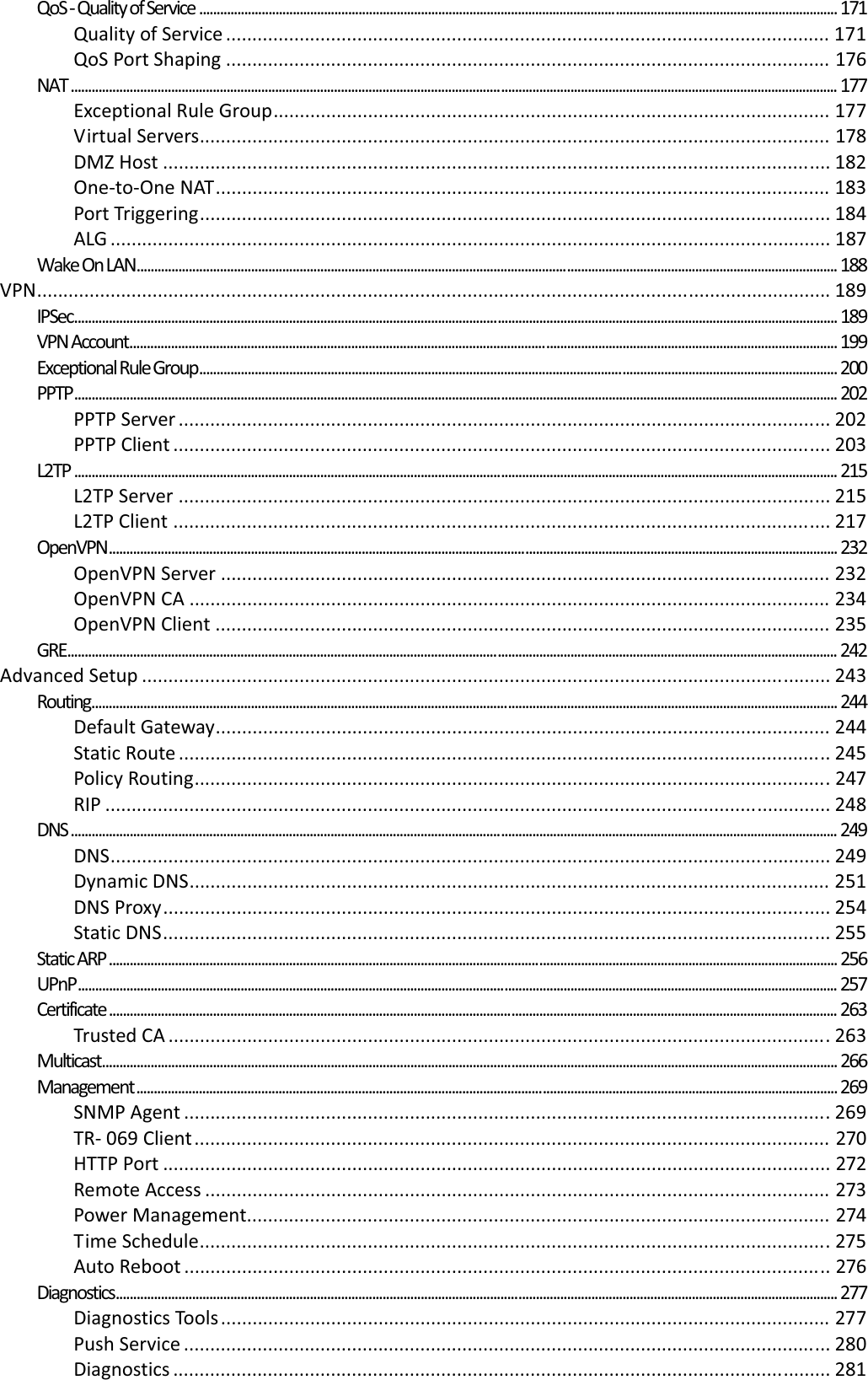
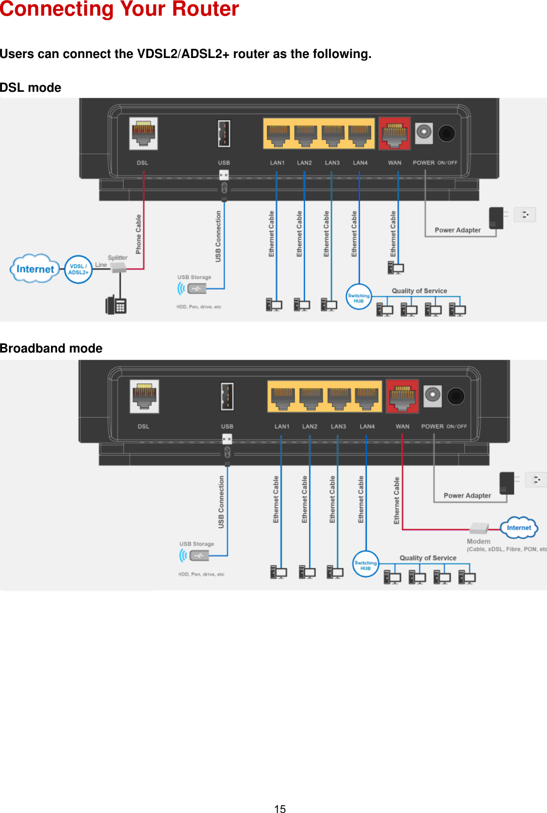
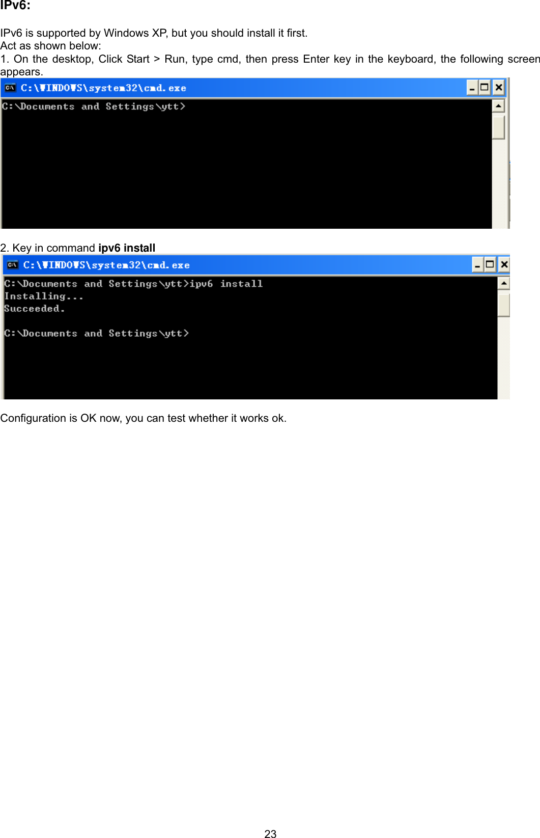
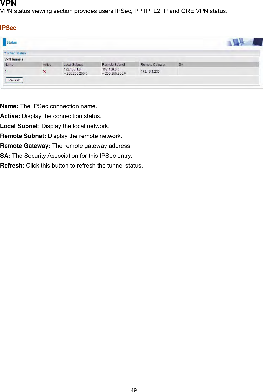
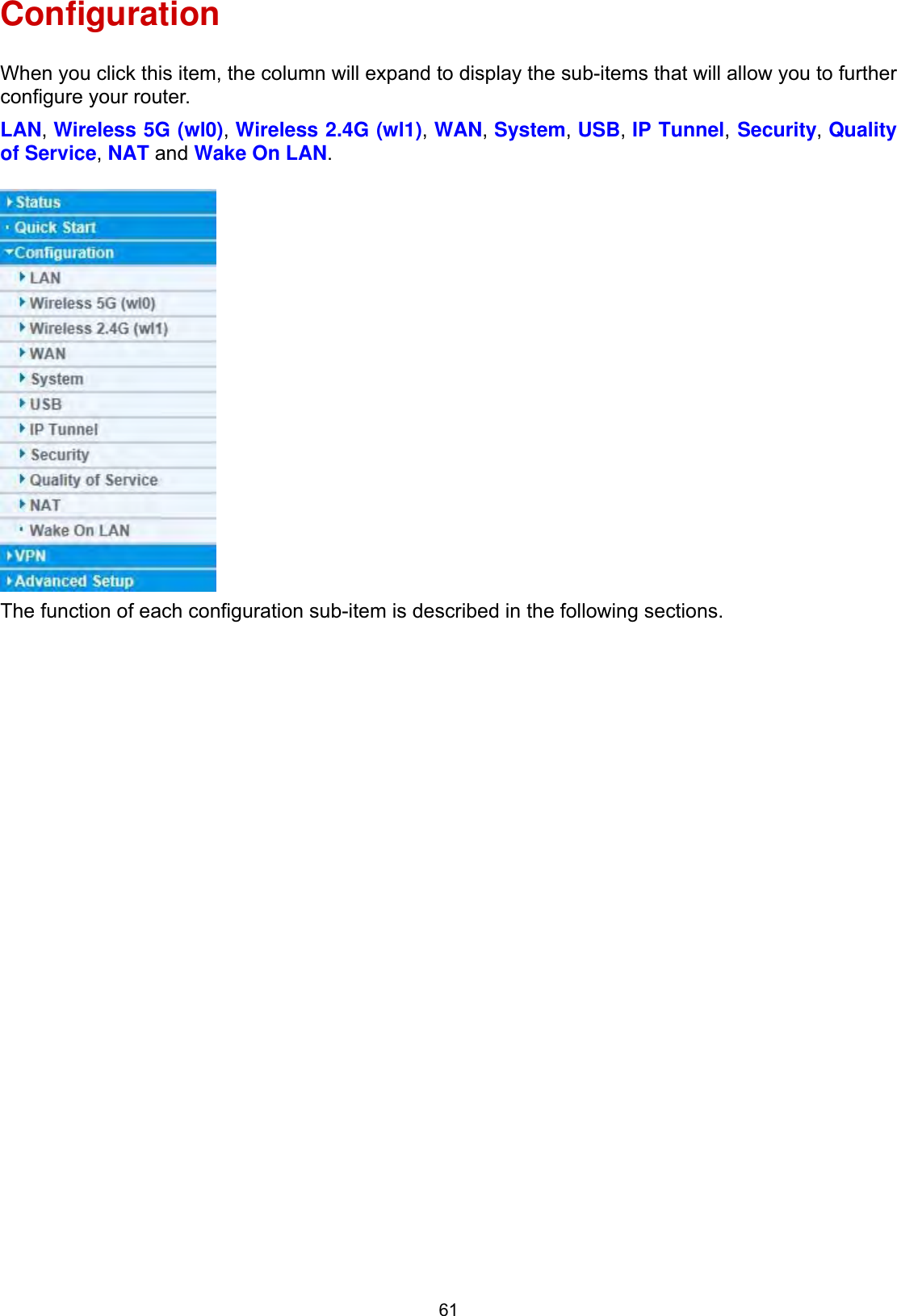
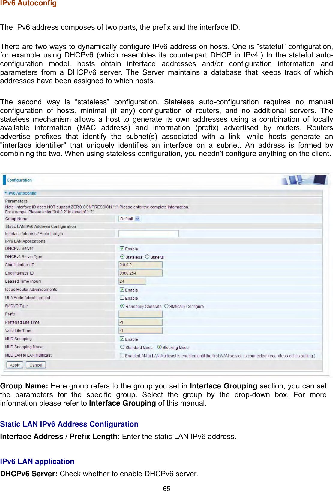
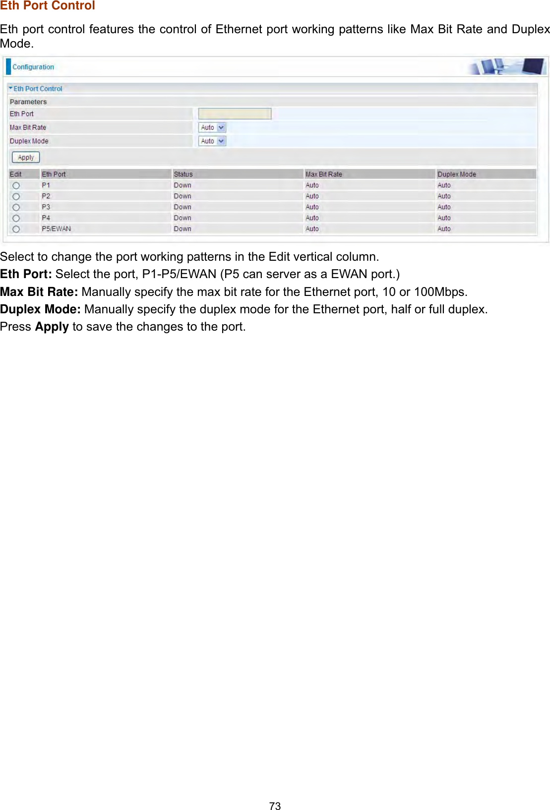
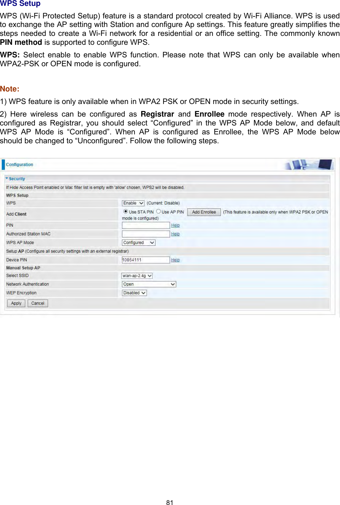
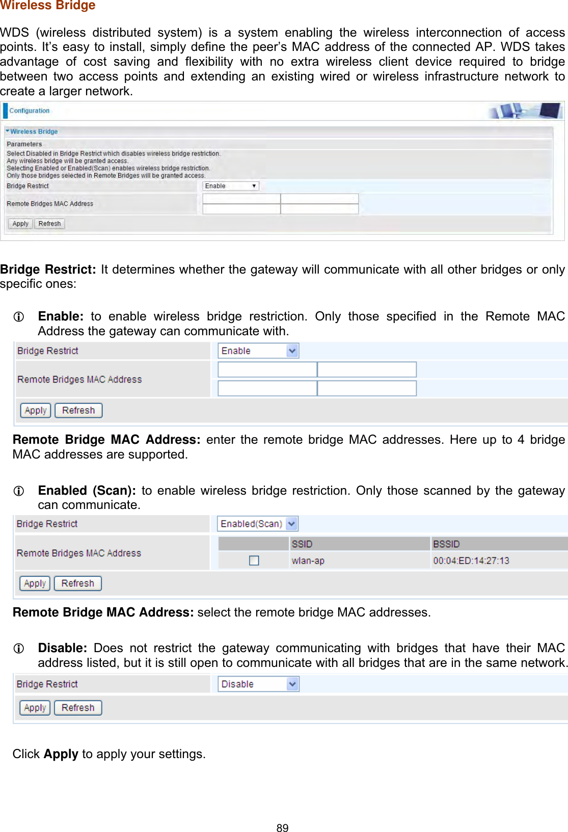
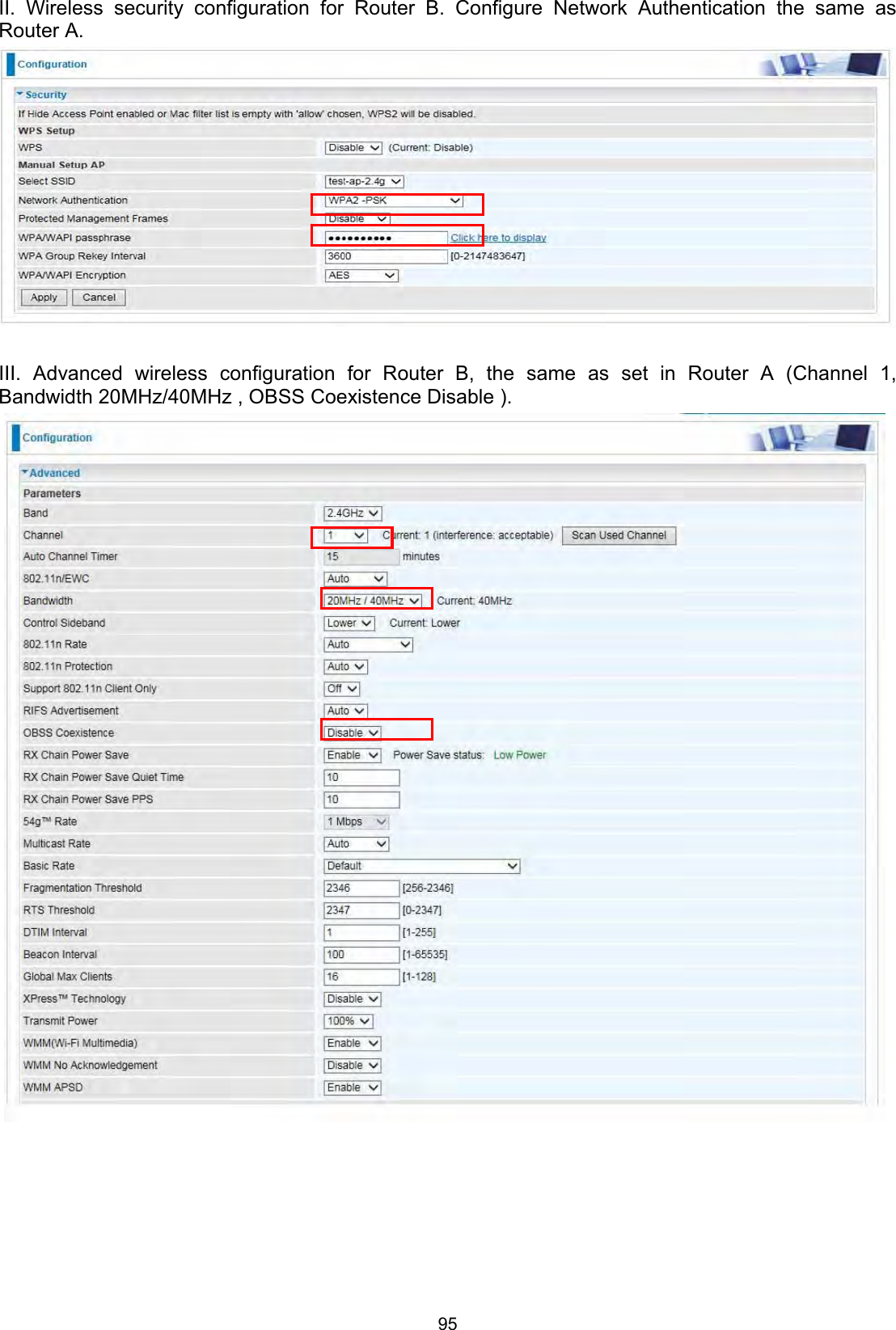
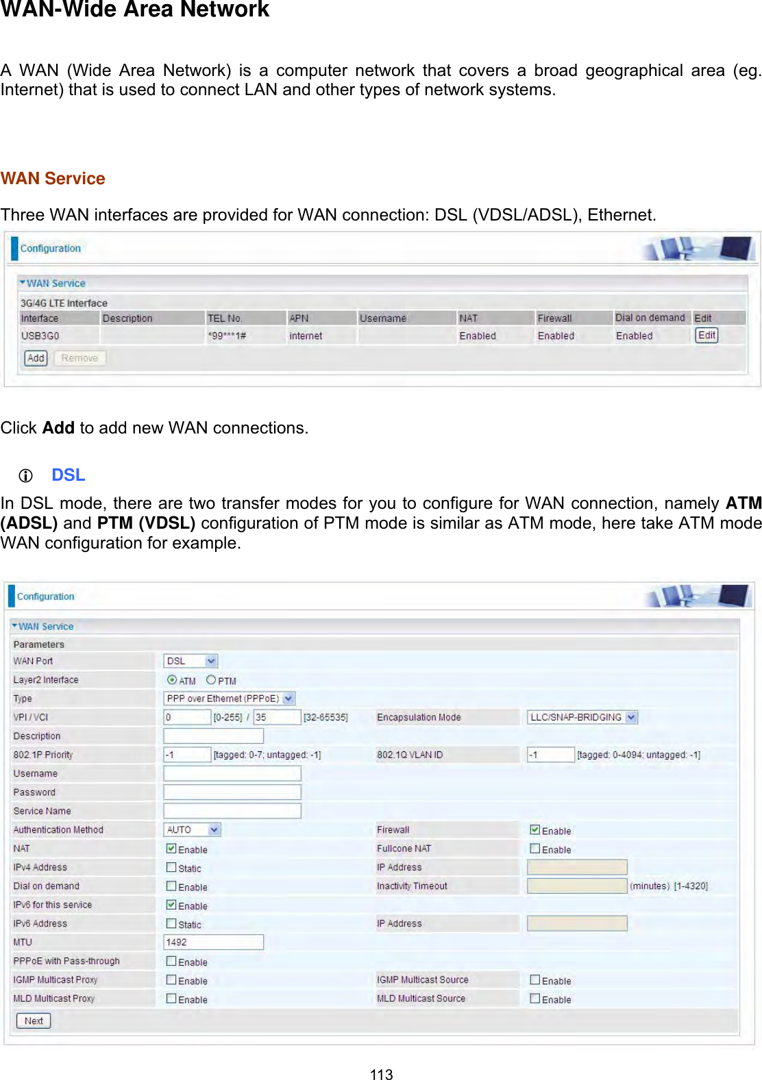
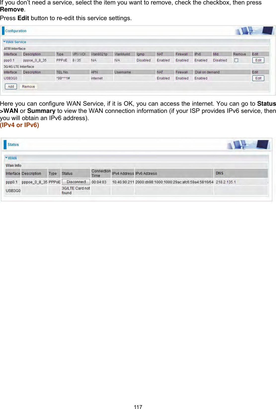
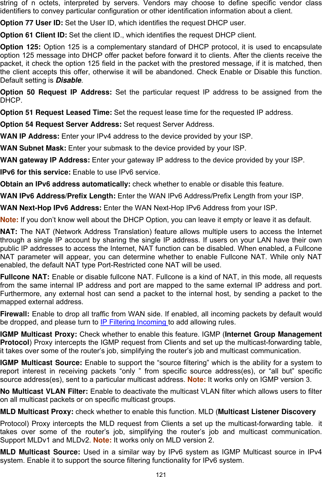
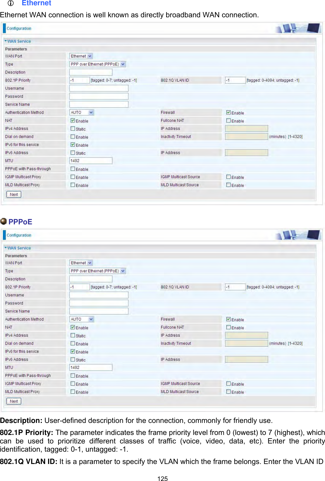
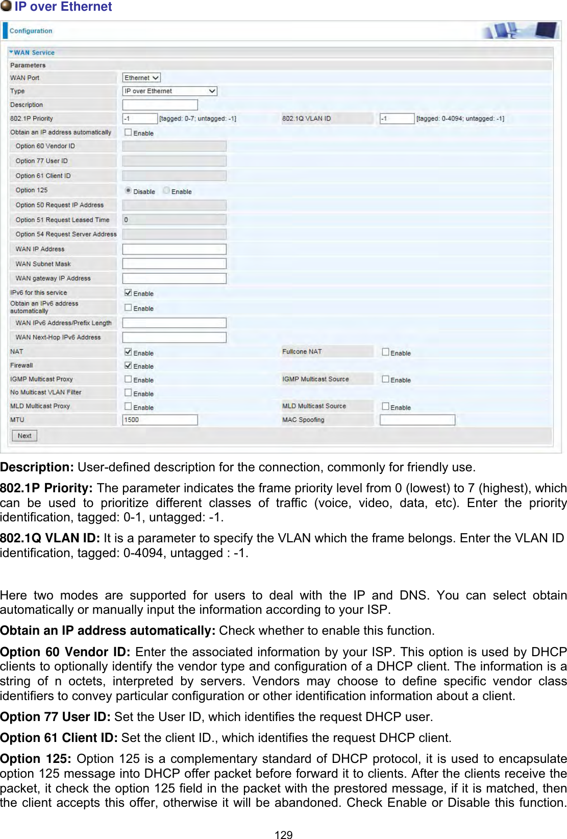
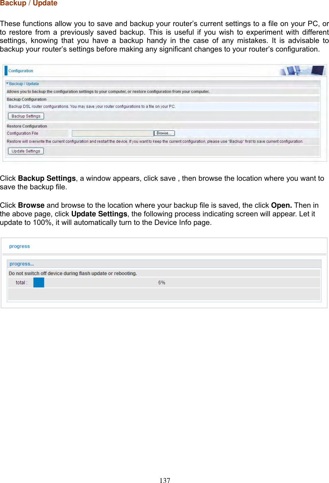
![110 check for radar on a channel before the Access Point establishes a wireless network with the channel.In-Network Radar Check (Used for 802.11h only): After the wireless network got established, specifies a period of time in seconds [10-99] to check for radar when switching to another non-radar channel.TPC Mitigation (db): Known as Transmitter Power Control mitigation to reduce unnecessary transmitting power radio and possible radio interference to other users.Transmit Power: select the transmitting power of your wireless signal.WMM (Wi-Fi Multimedia): you can choose to enable or disable this function which allows for priority of certain data over wireless network.WMM No Acknowledgement: Refers to the acknowledge policy at the MAC level. Enabling WMM No Acknowledgement can result in more efficient throughput but higher error rates in noisy Radio Frequency (RF) environment.WMM APSD: Automatic Power Save Delivery. Enable this to save power.](https://usermanual.wiki/Billion-Electric/BIL-8700AXL.User-Manual-Part-1/User-Guide-3810626-Page-115.png)
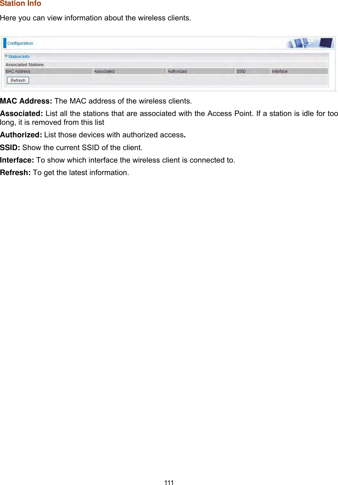
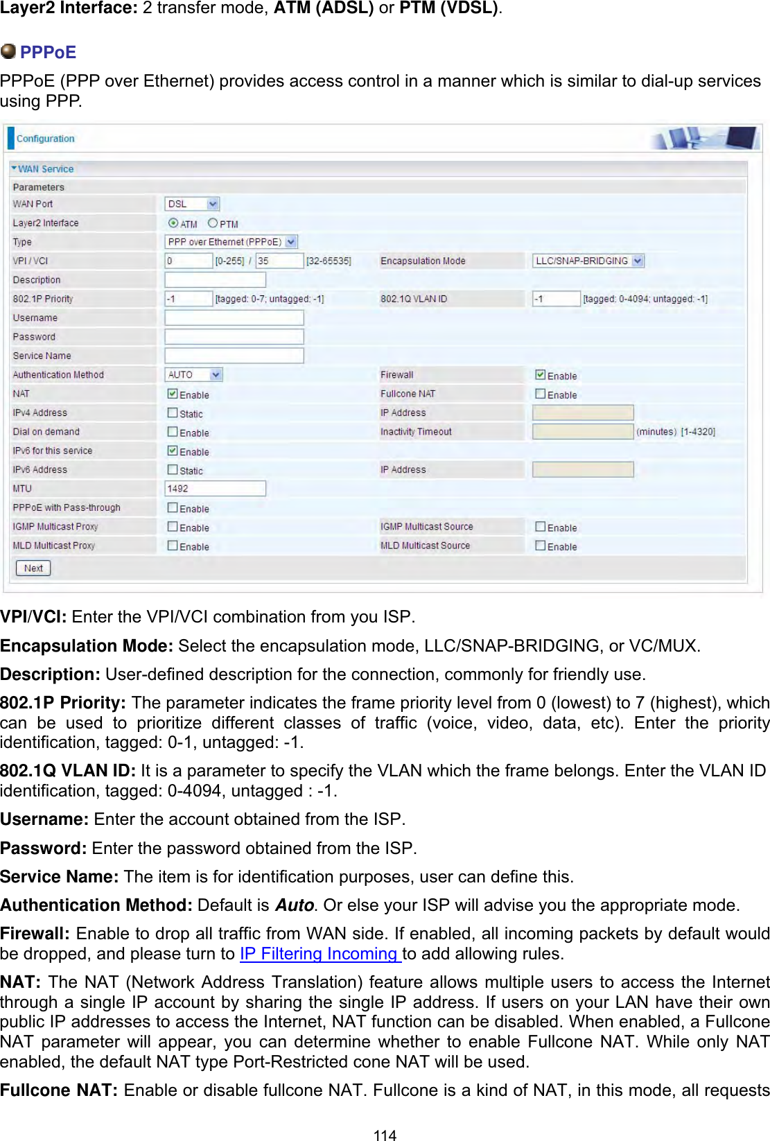
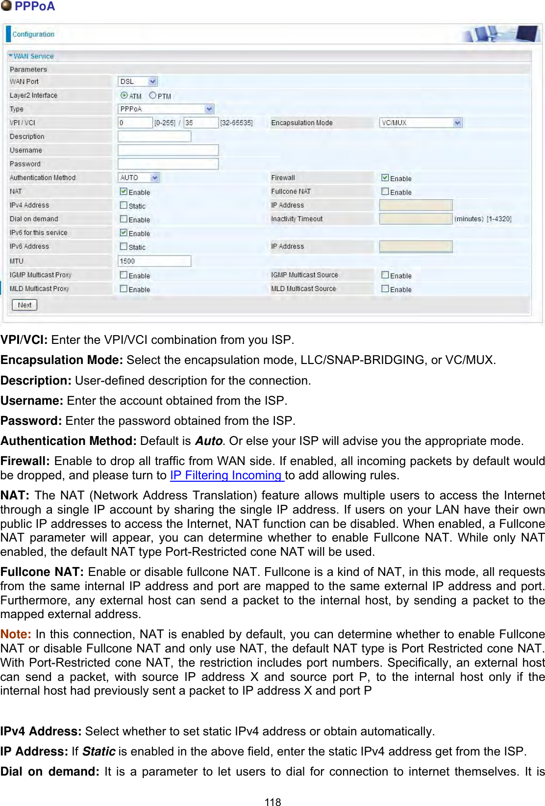
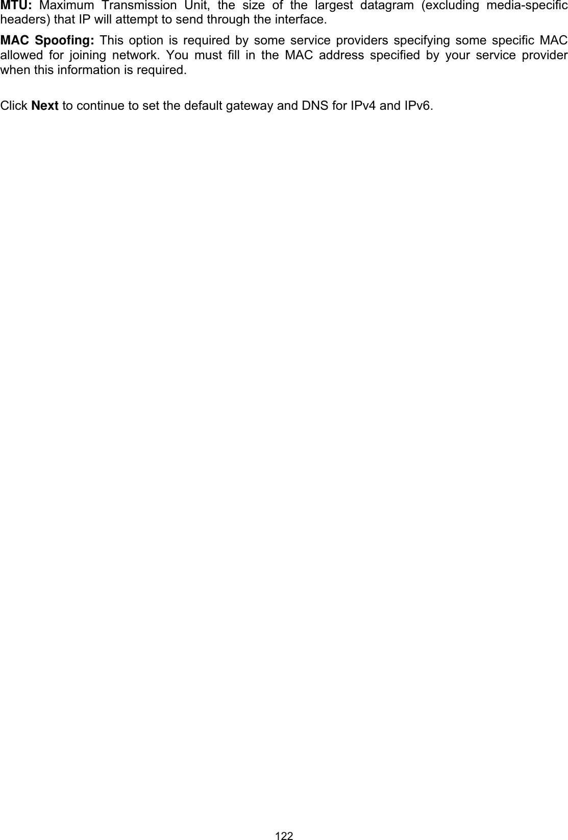
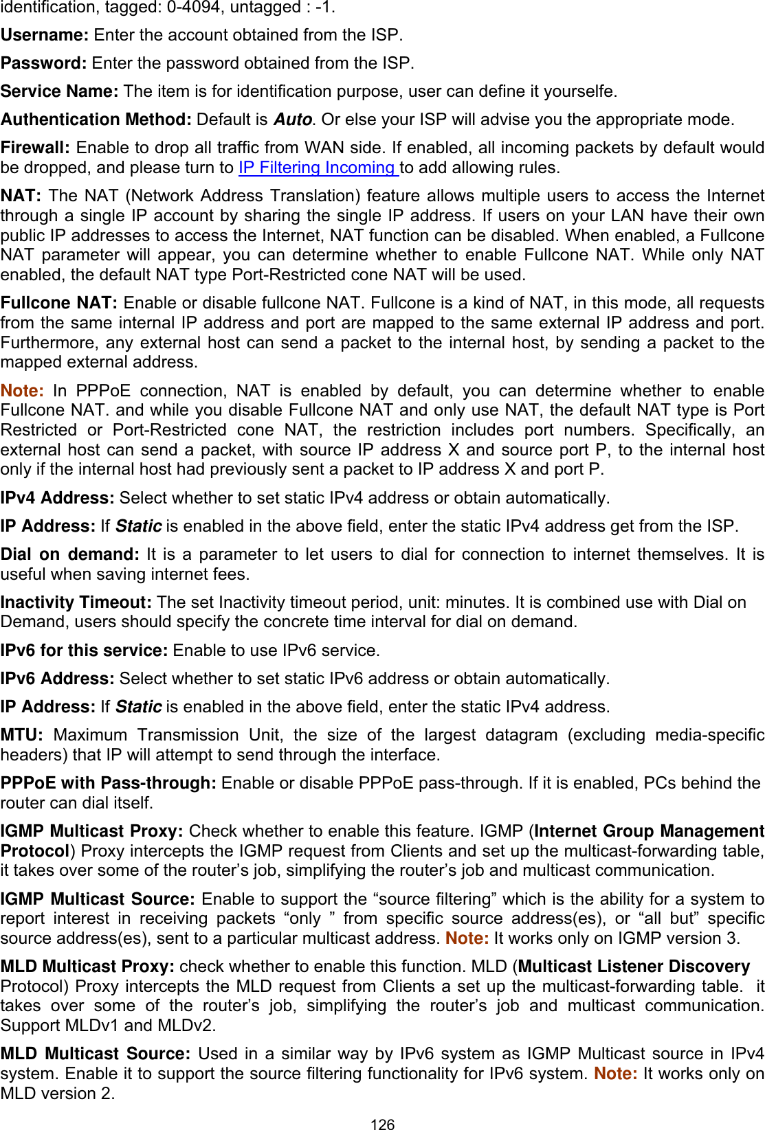
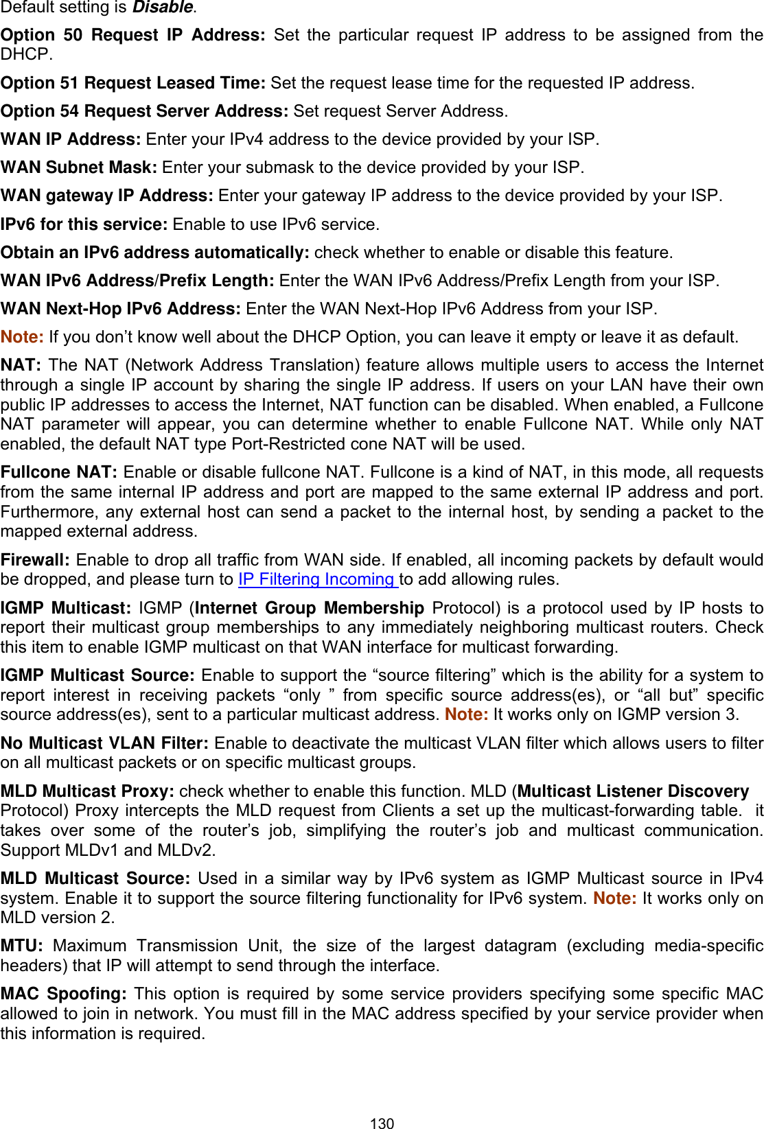
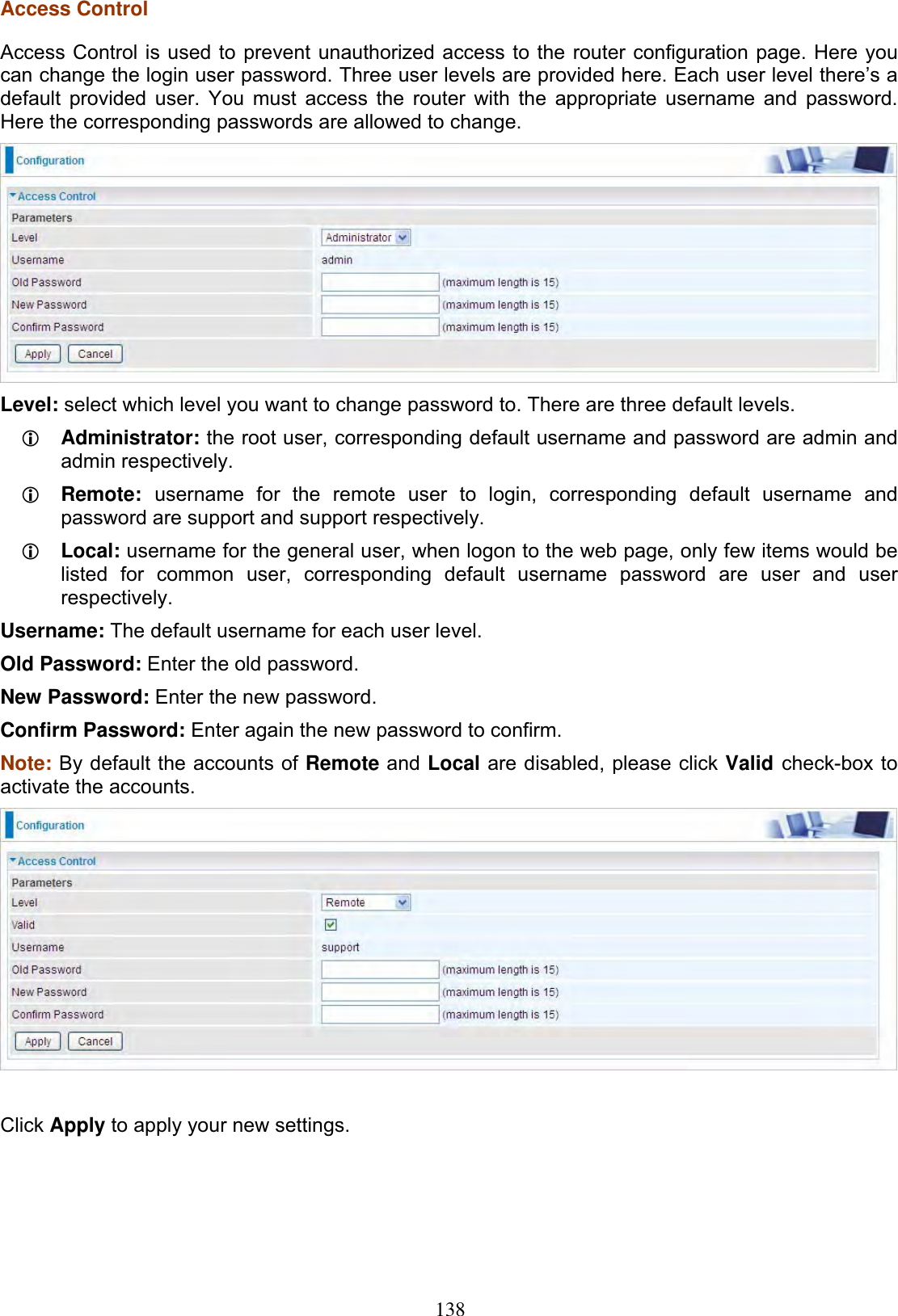
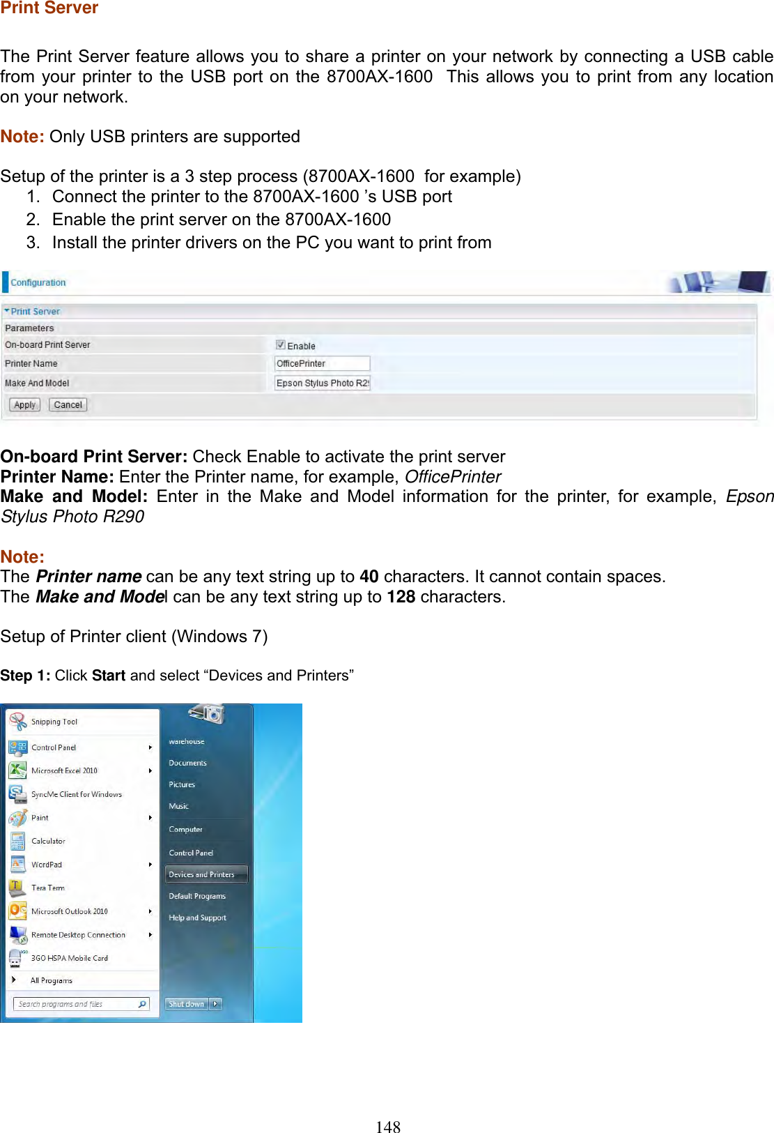
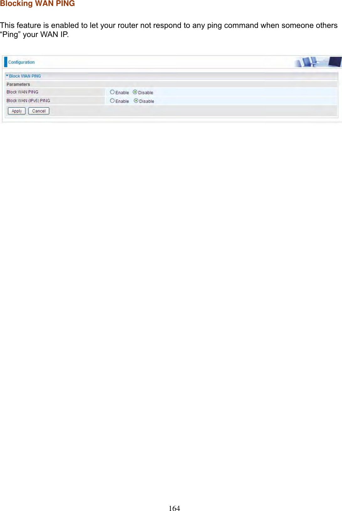
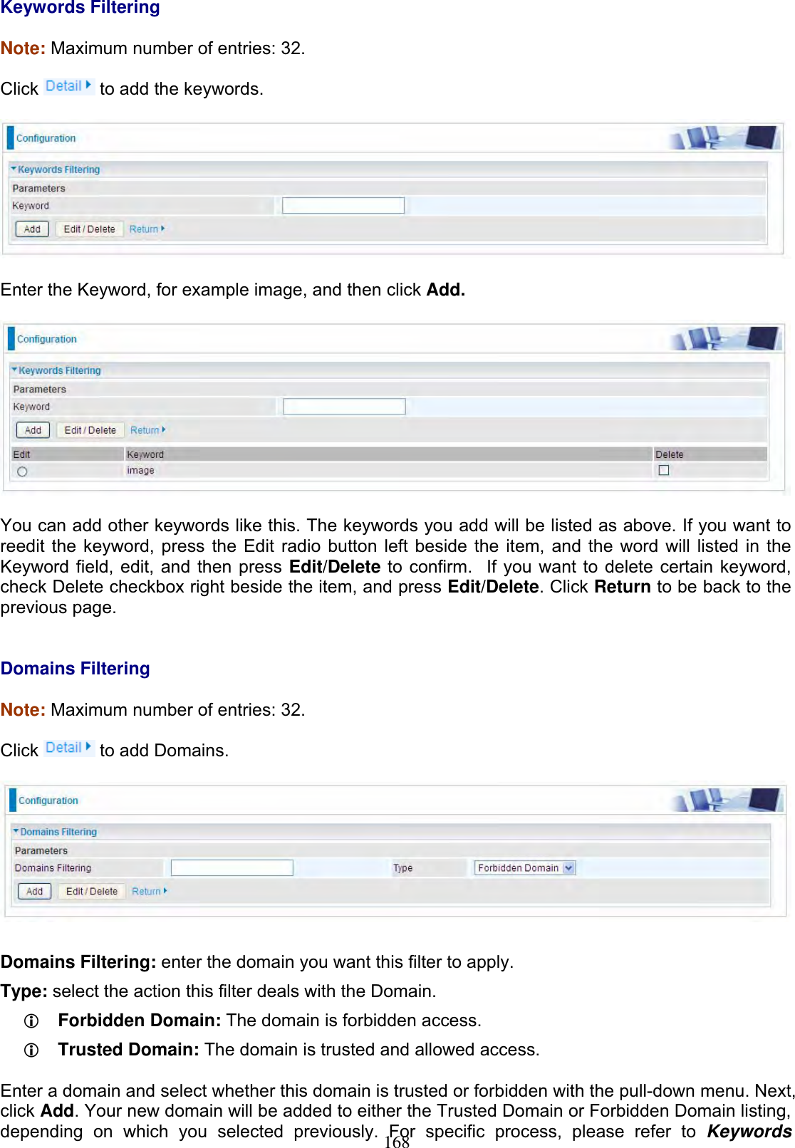
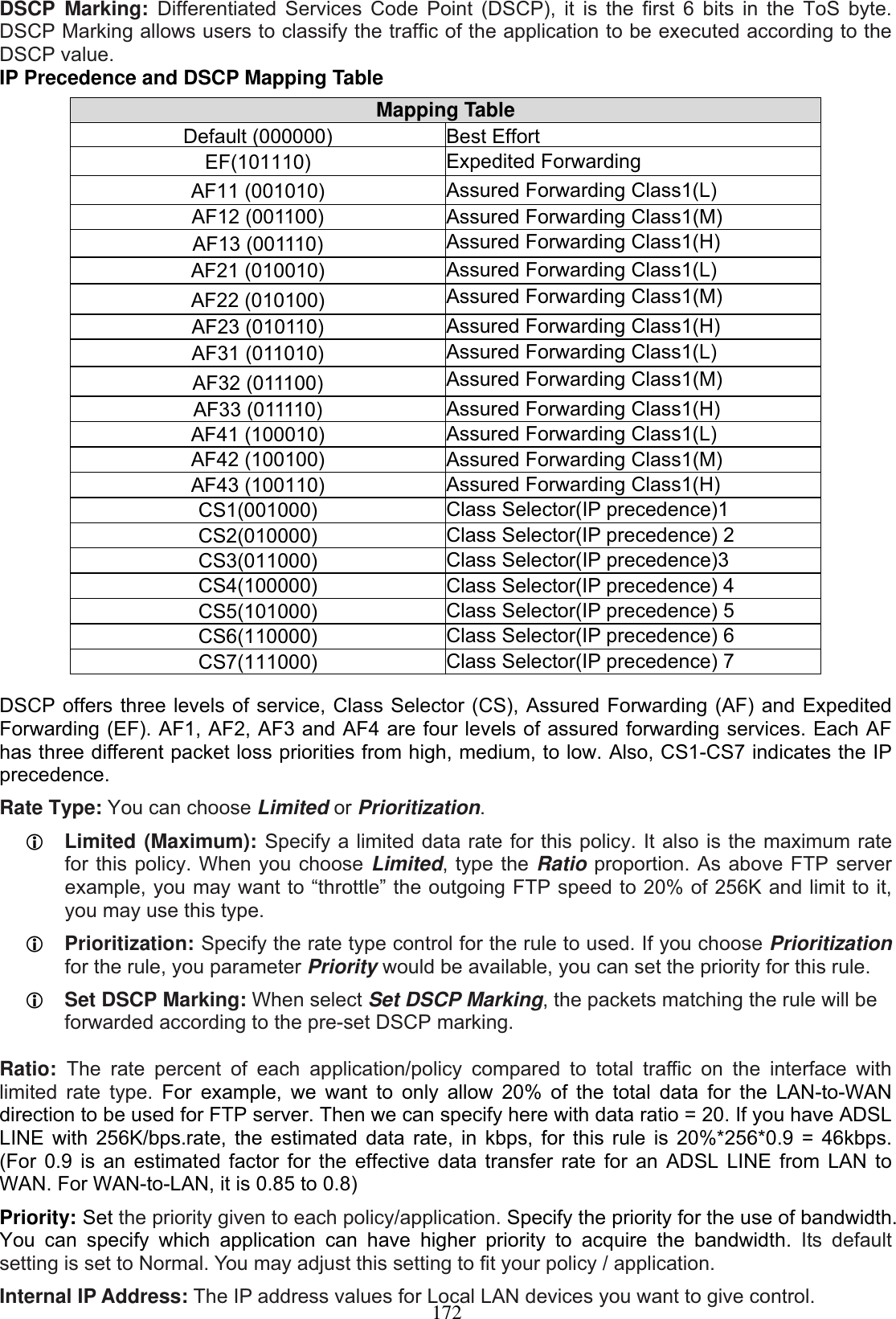
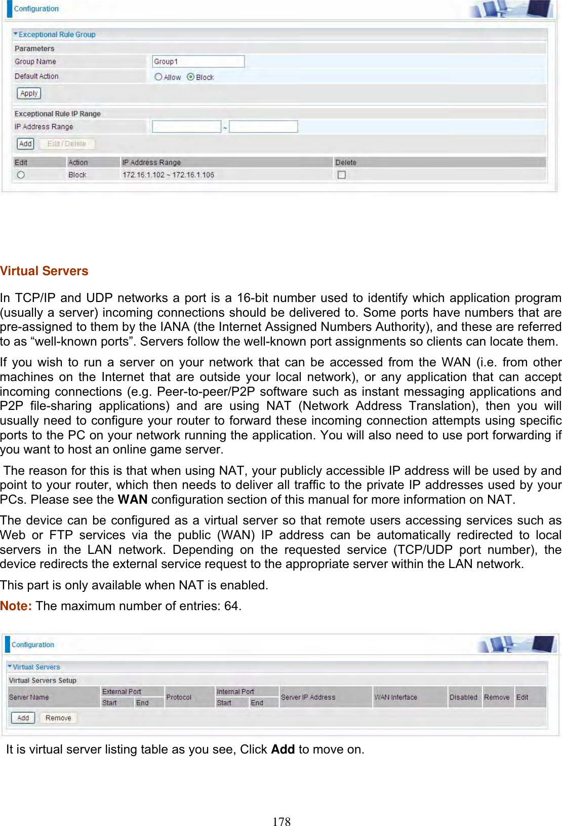
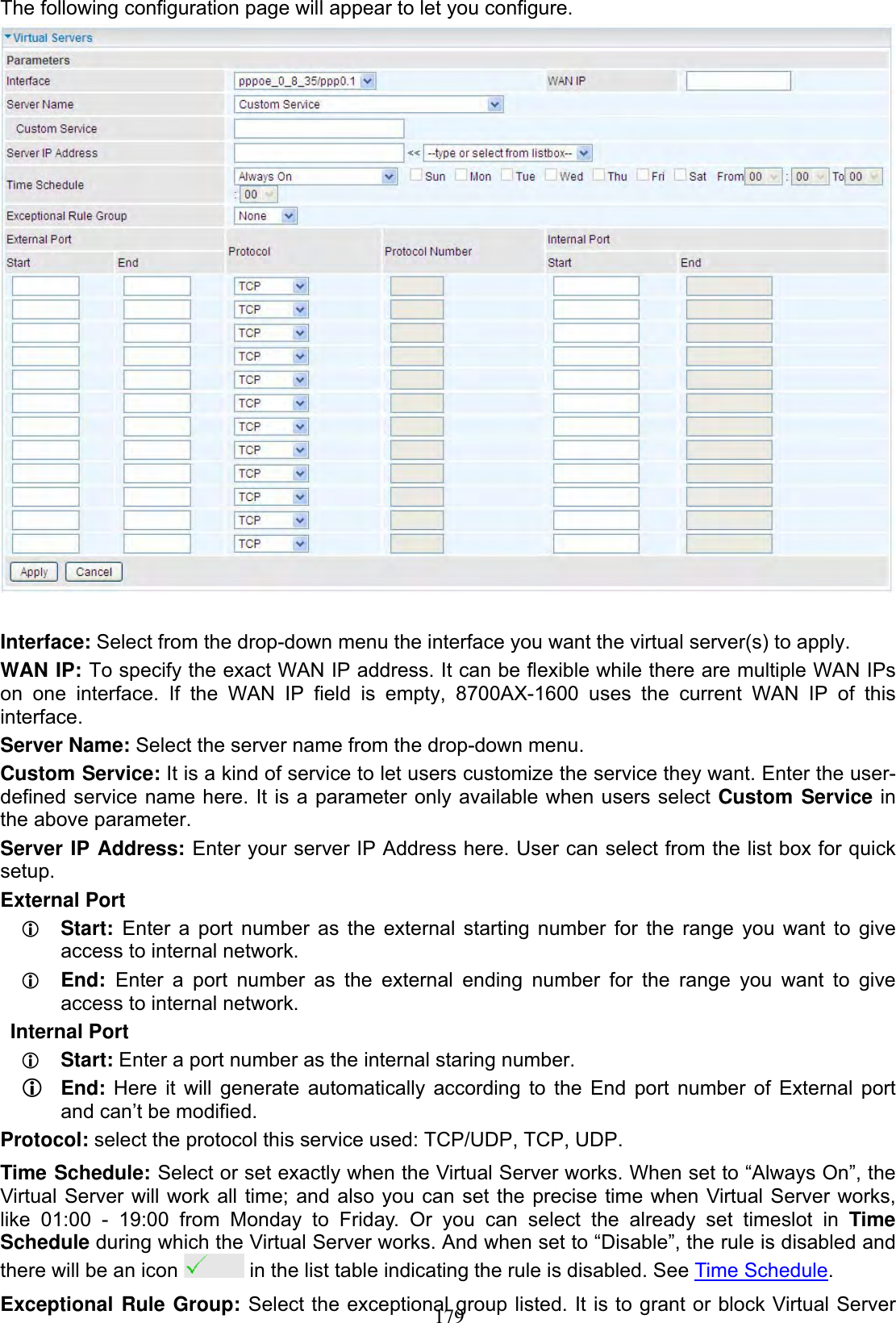
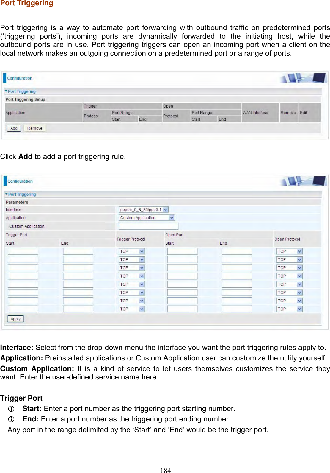
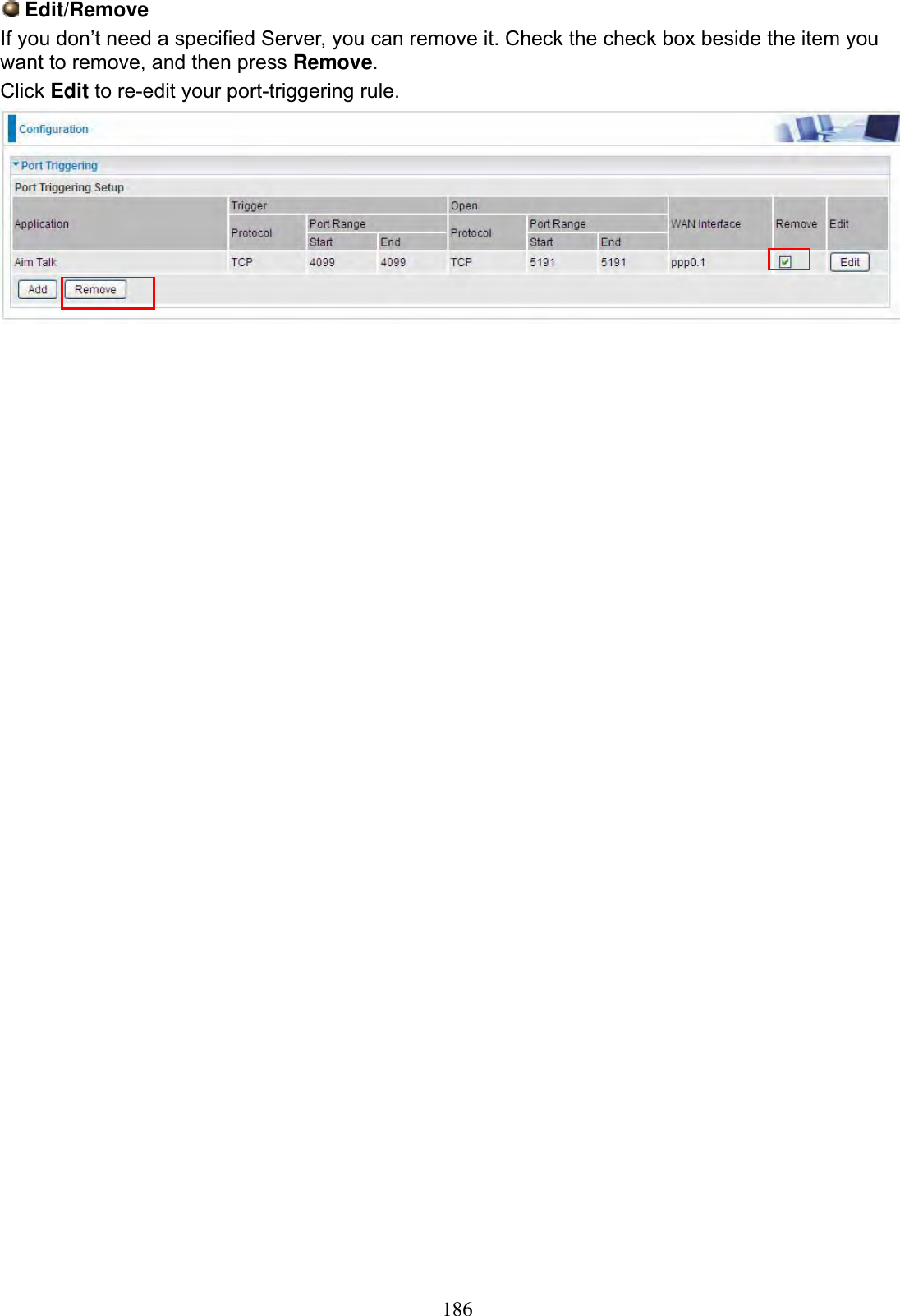
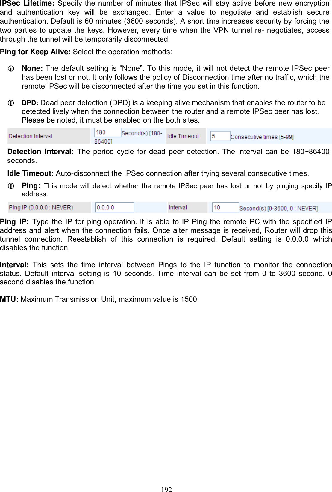
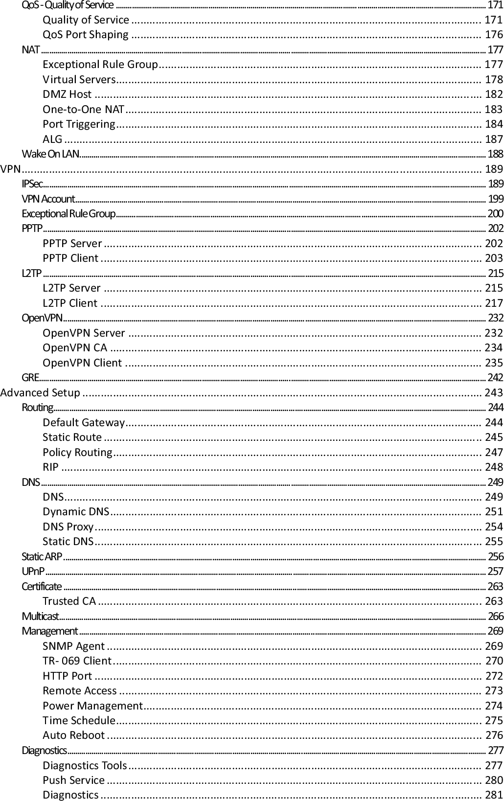
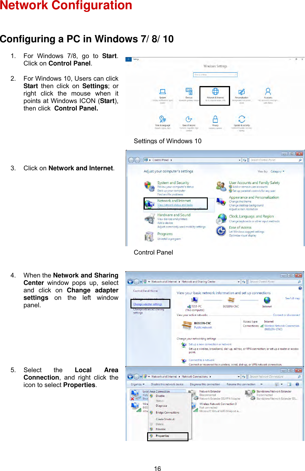
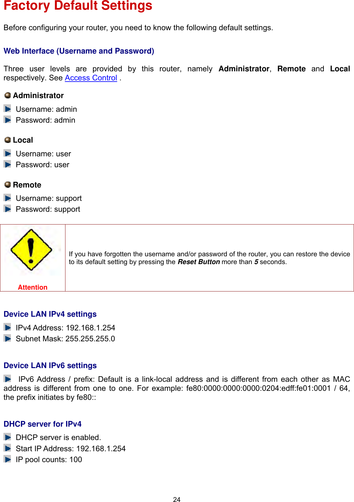
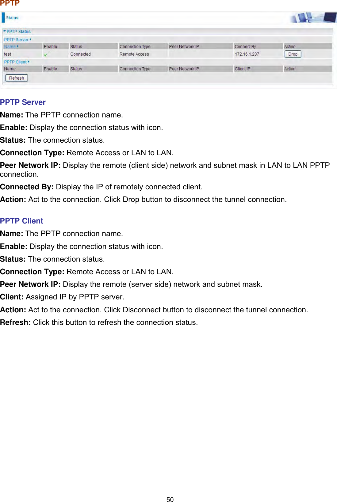
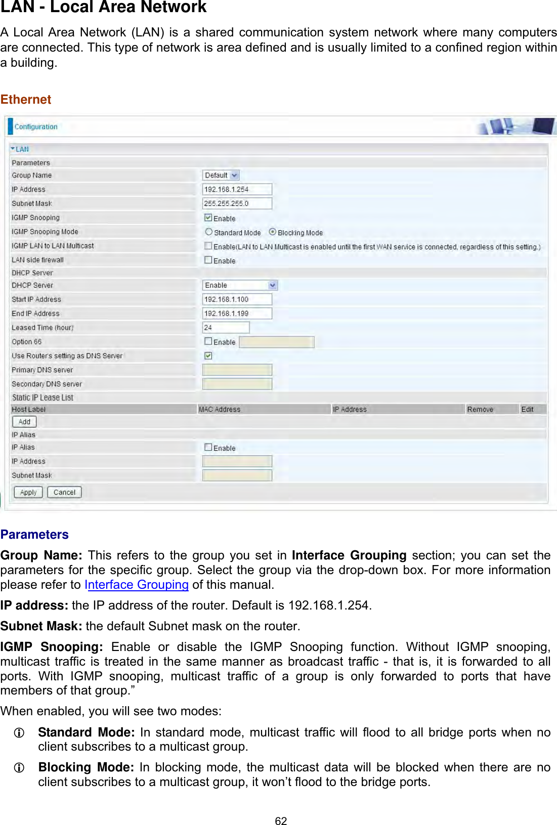
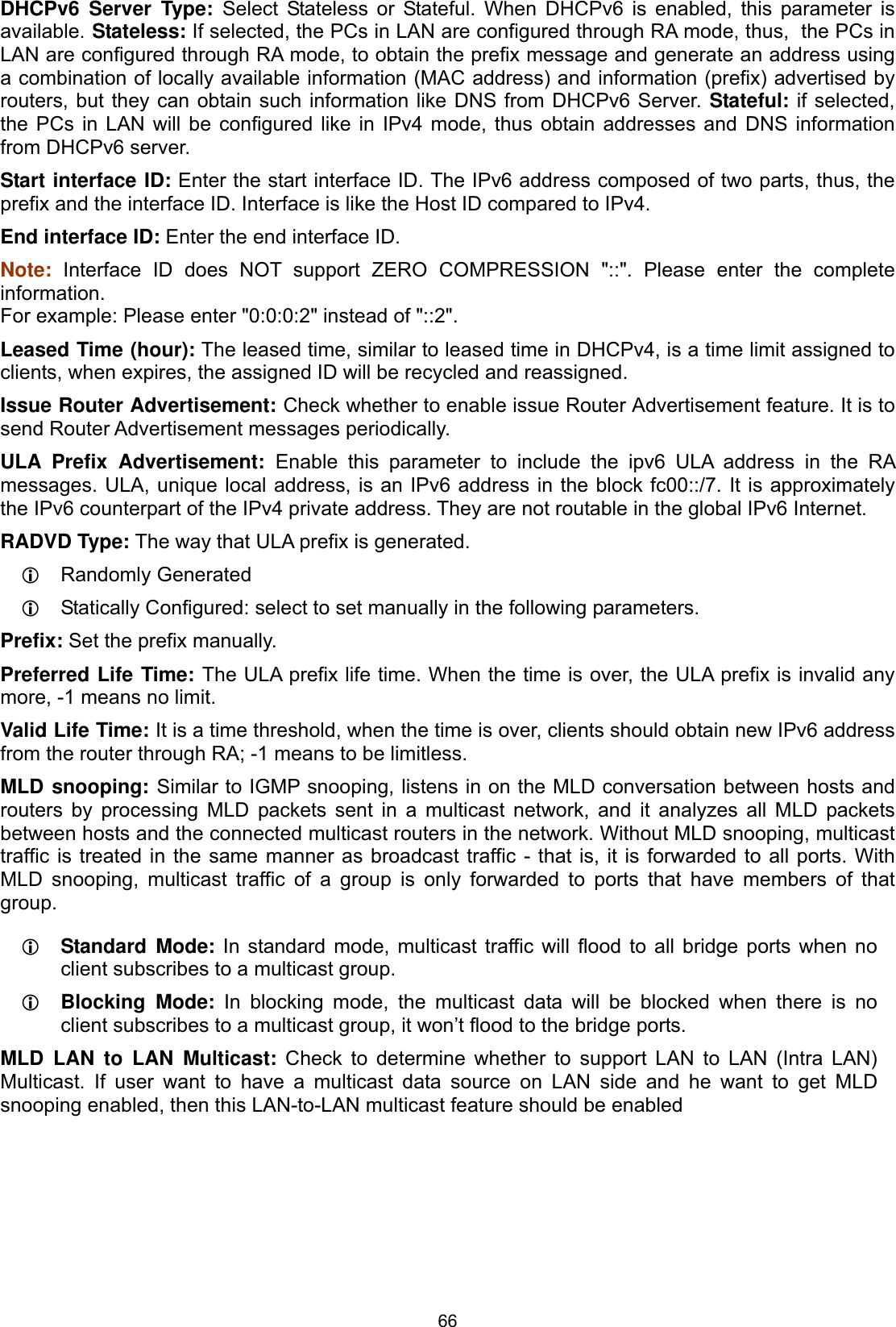
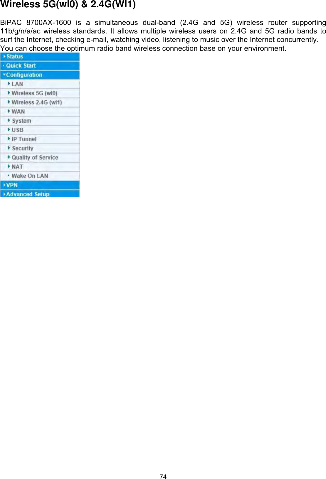
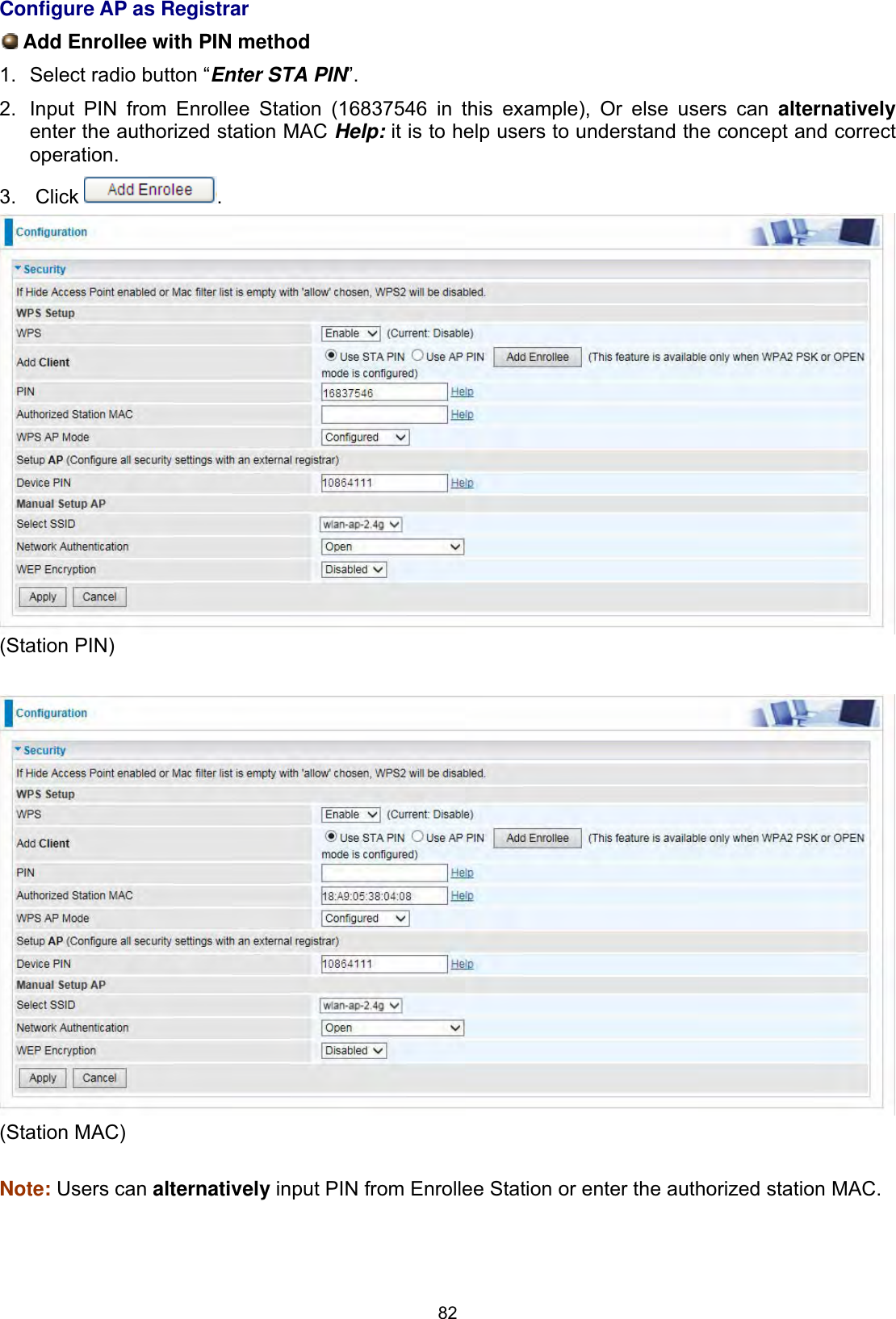
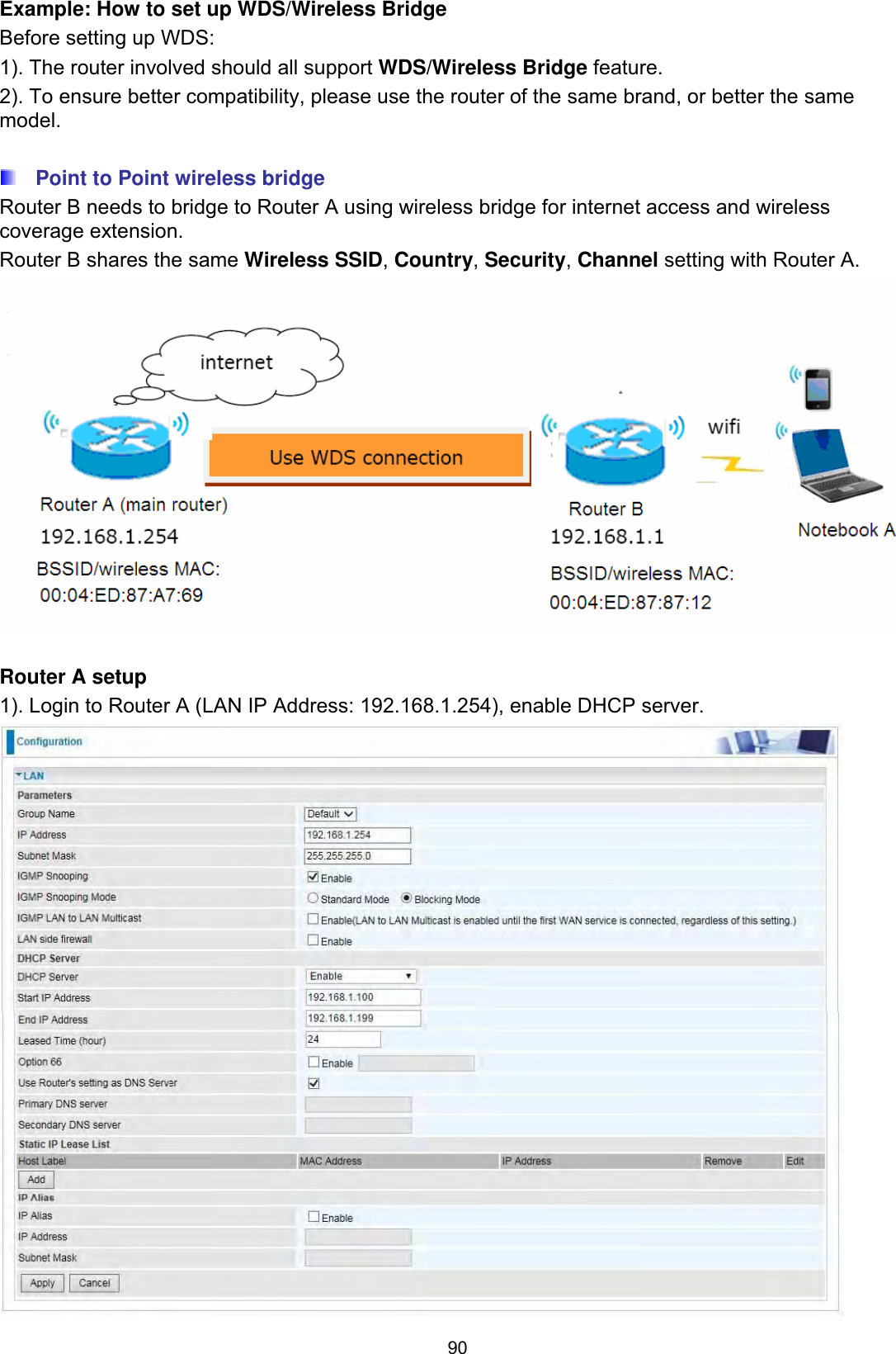
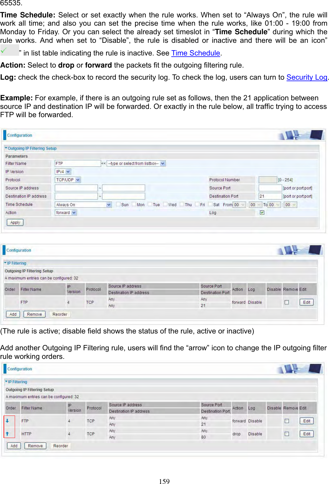
![158SecurityIP Filtering Outgoing IP filtering enables you to configure your router to block specified internal/external users (IP address)from Internet access, or you can disable specific service requests (Port number) to /from Internet. The relationship among all filters is “or” operation, which means that the router checks these different filter rules one by one, starting from the first rule. As long as one of the rules is satisfied, the specified action will be taken. Note: The maximum number of entries: 32. Click Add button to enter the exact rule setting page. Filter Name: A user-defined rule name. User can select simply from the list box for the application for quick setup.IP Version: Select the IP Version, IPv4 or IPv6. Protocol: Set the traffic type (TCP/UDP, TCP, UDP, ICMP, RAW, Any) rule applies to.Source IP address: This is the Address-Filter used to allow or block traffic to/from particular IP address(es) featured in the IP range. If you leave empty, it means any IP address. Source Port [port or port:port]: The port or port range defines traffic from the port (specific application) or port in the set port range blocked to go through the router. Default is set port from range 1 – 65535.Destination IP address: Traffic from LAN with the particular traffic destination address specified in the IP range is to be blocked from going through the router, similarly set as the Source IP address above.Destination Port [port or port: port]: Traffic with the particular set destination port or port in the set port range is to be blocked from going through the router. Default is set port from port range: 1 –](https://usermanual.wiki/Billion-Electric/BIL-8700AXL.User-Manual-Part-1/User-Guide-3810626-Page-163.png)
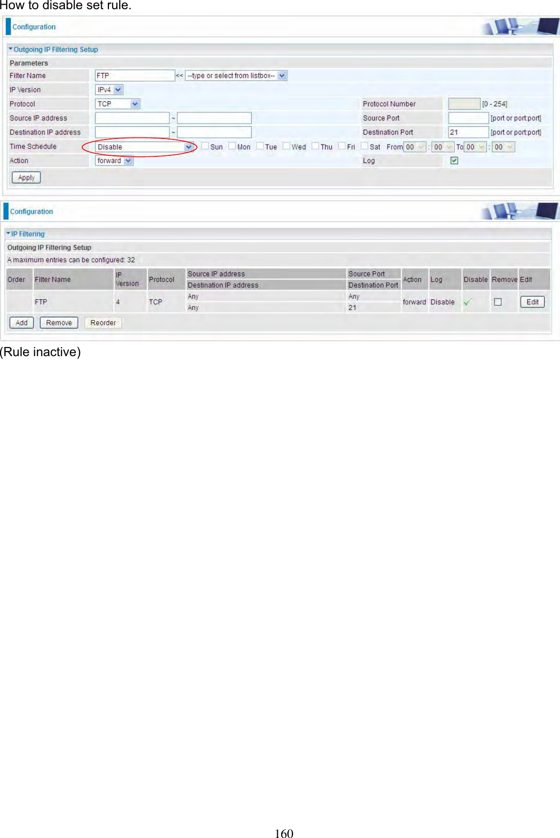
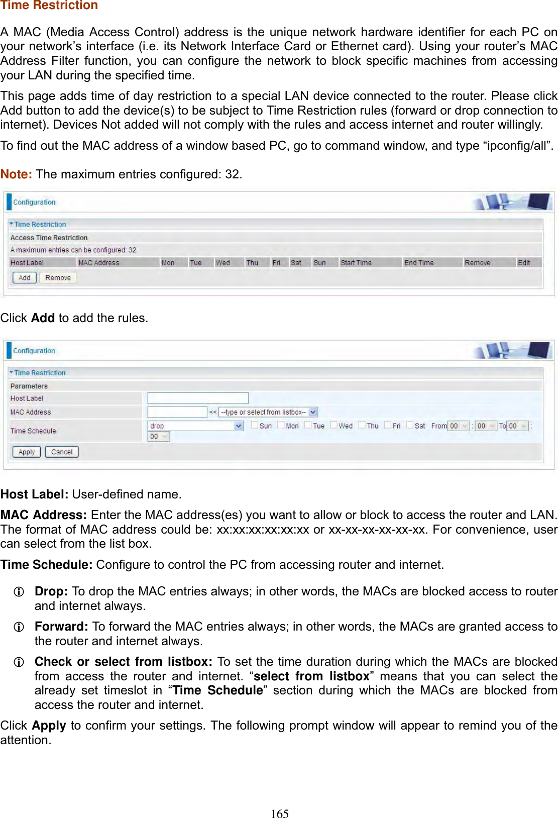
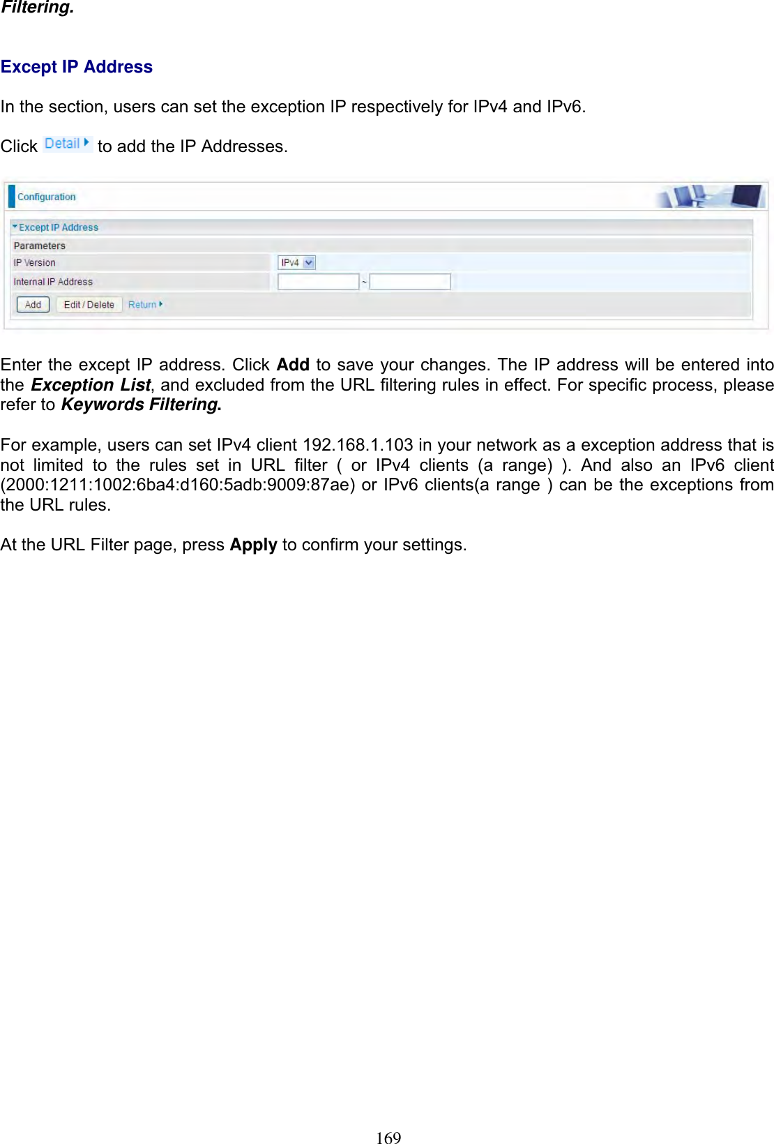
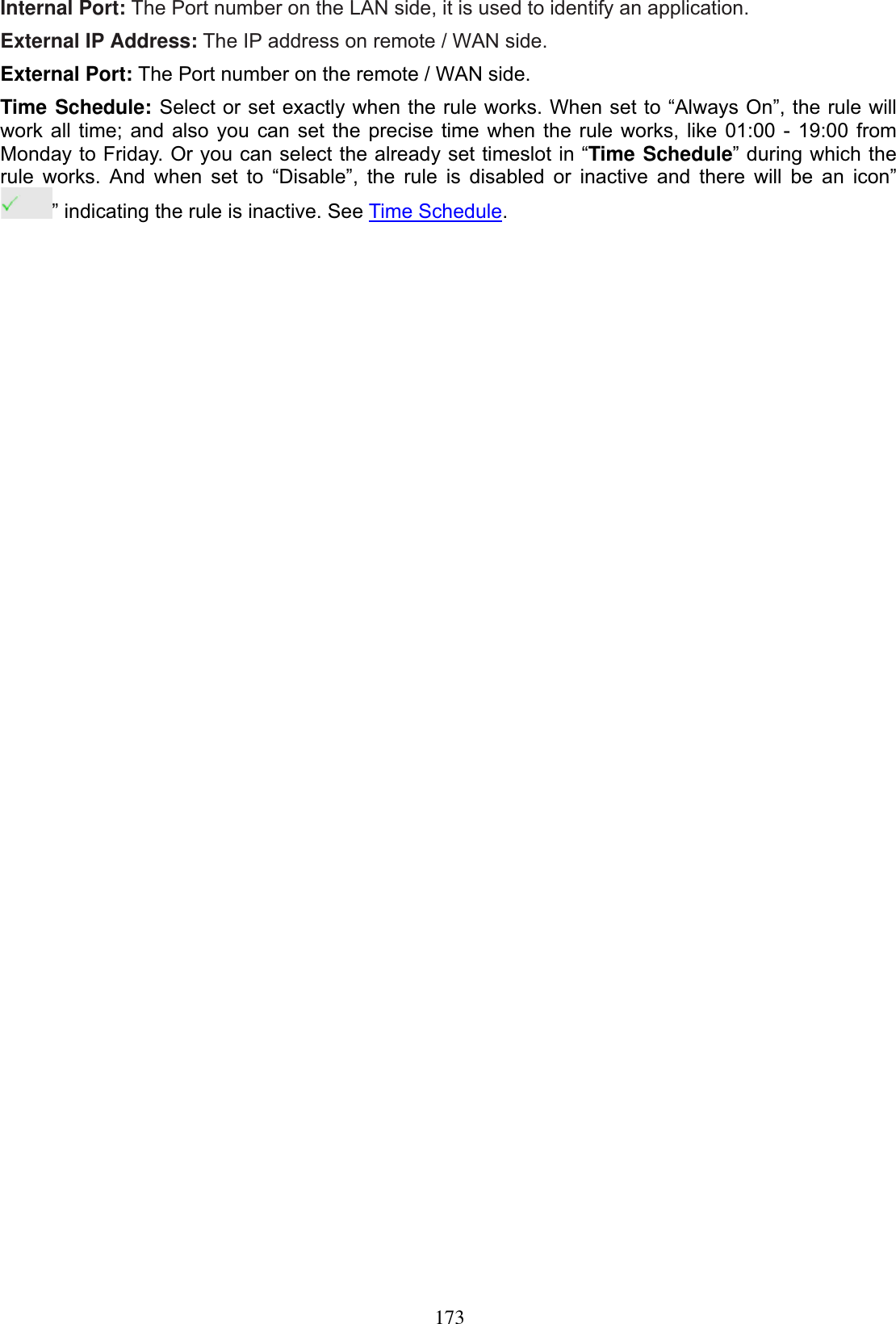
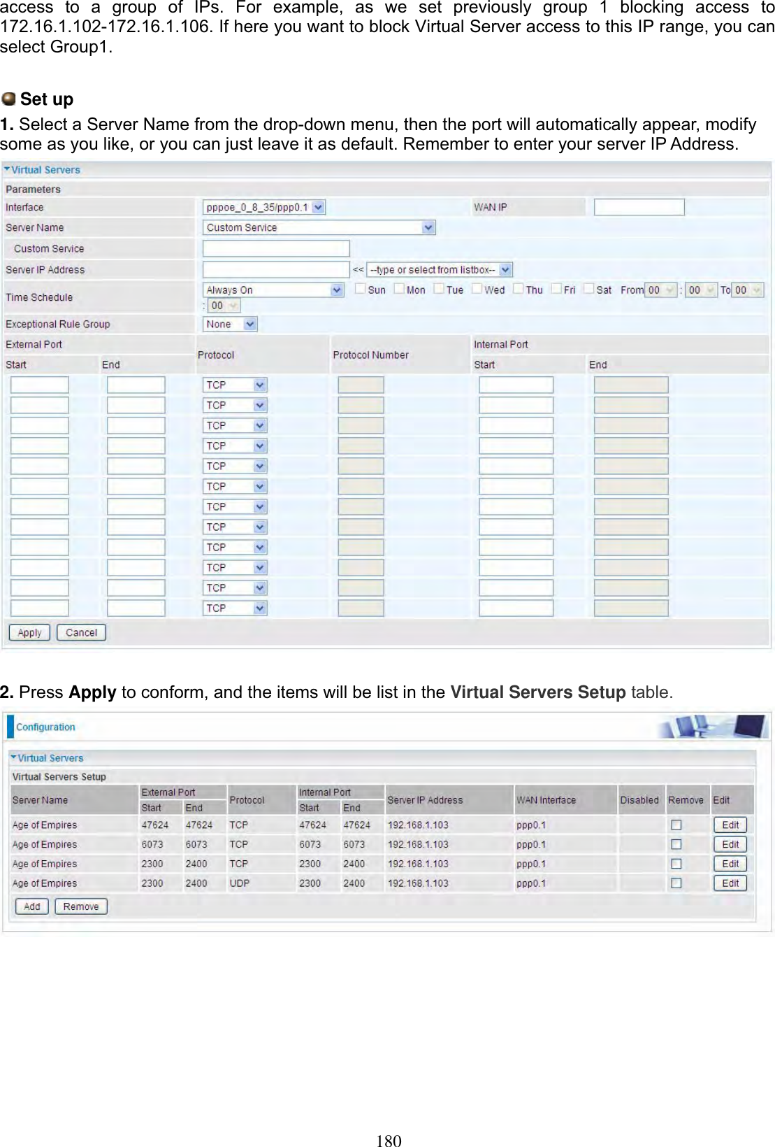
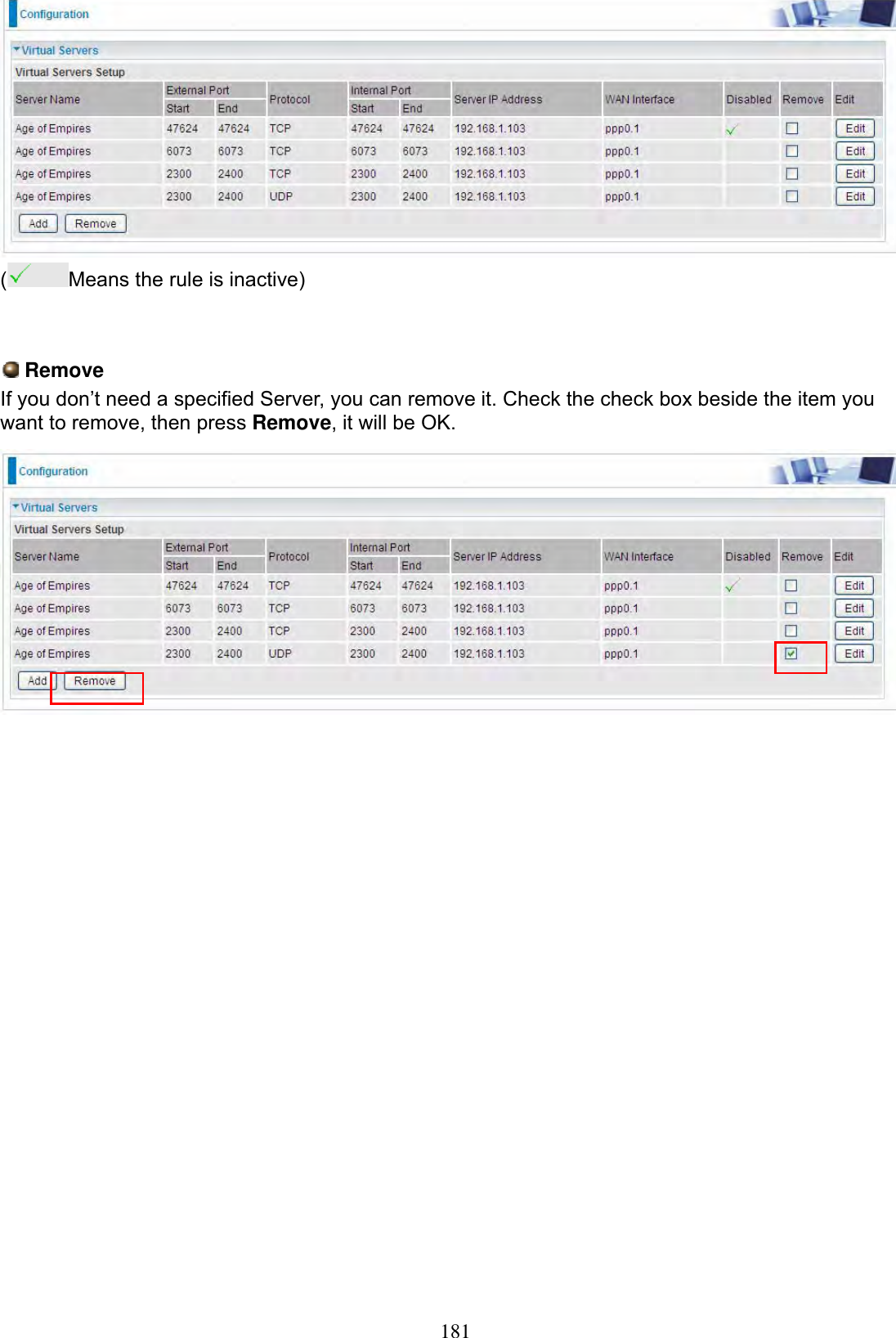
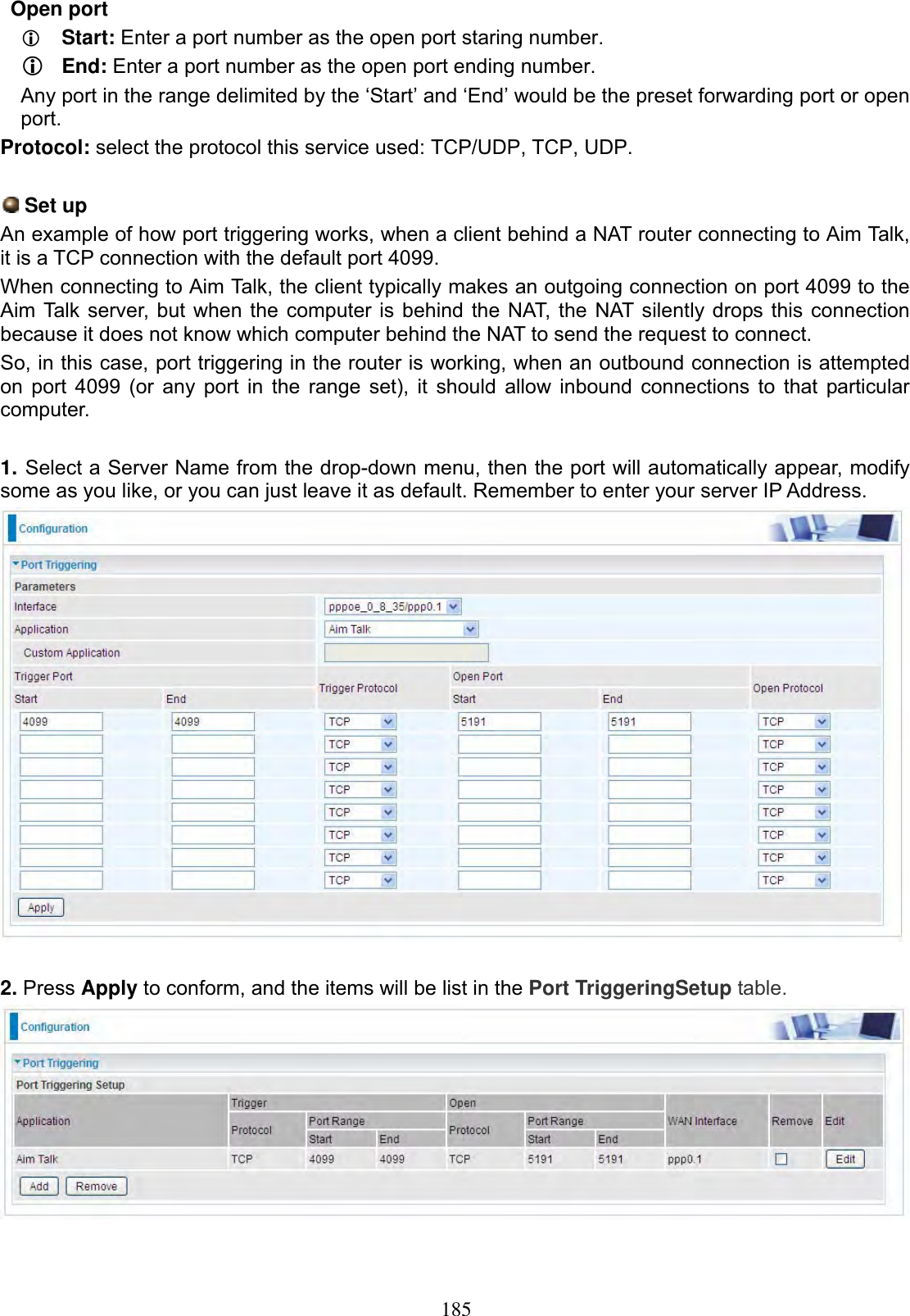
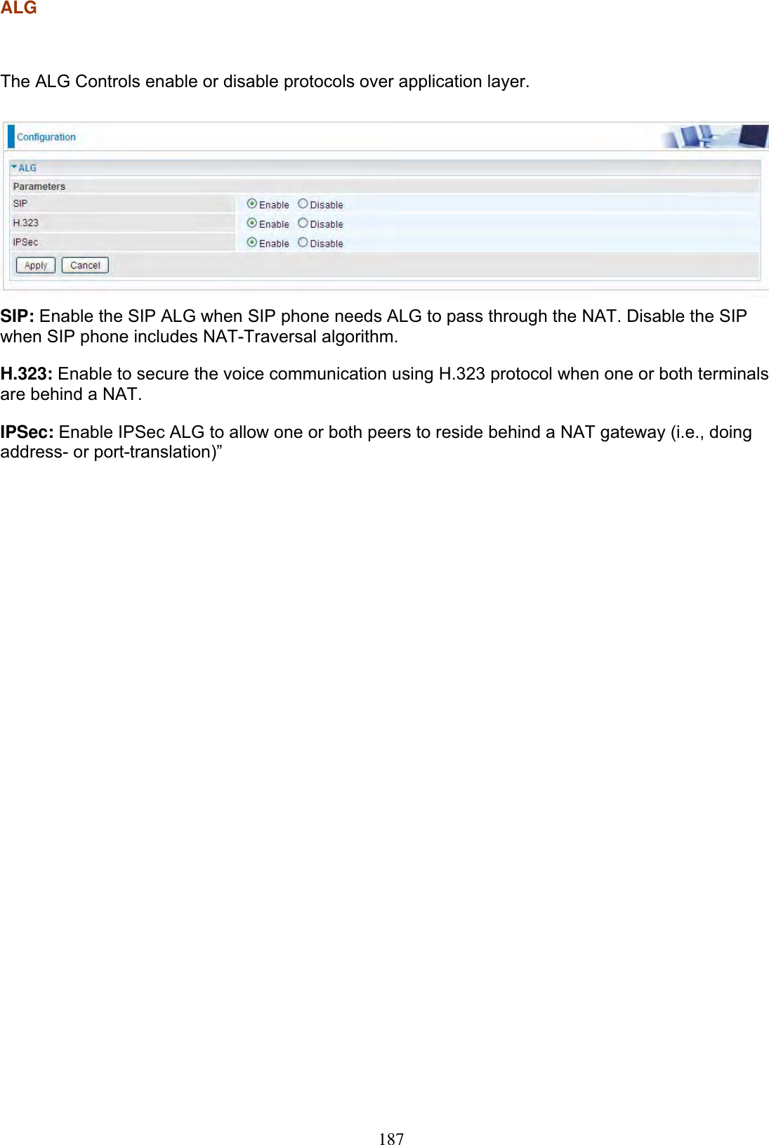
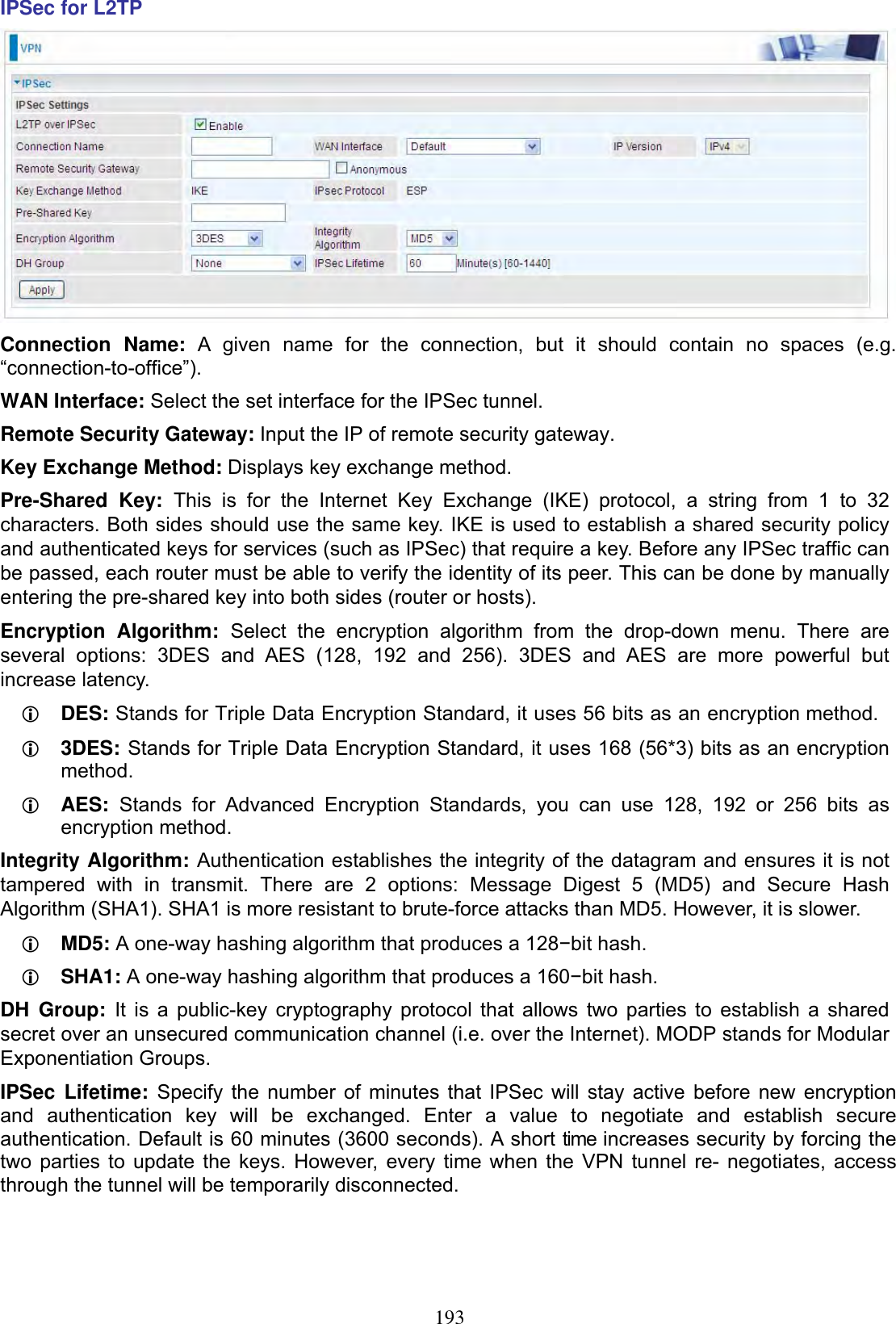
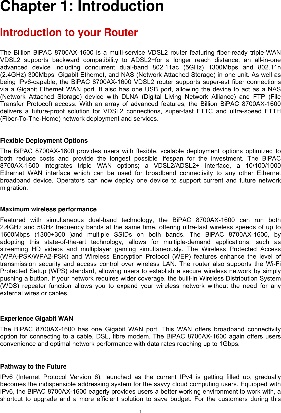
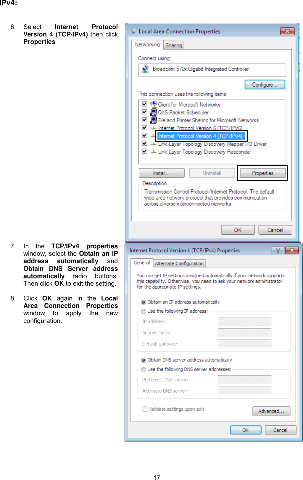
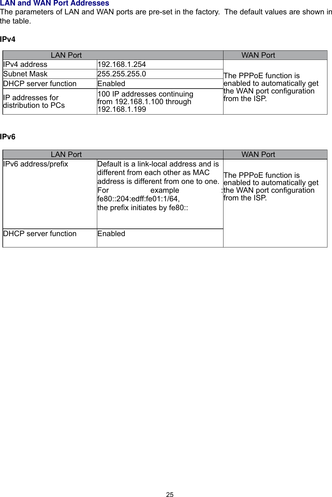
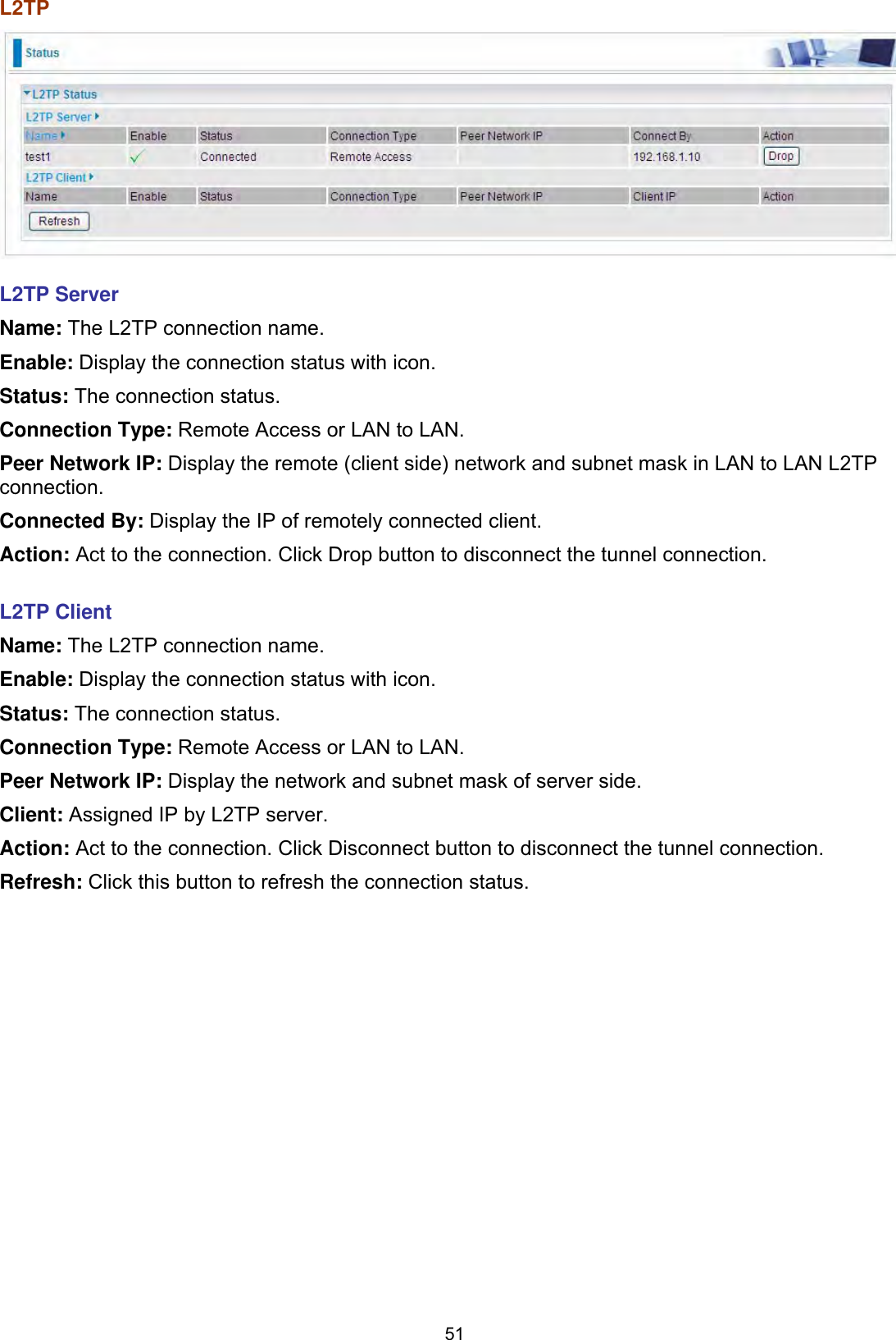
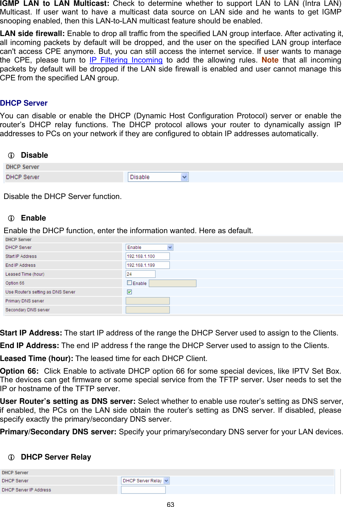
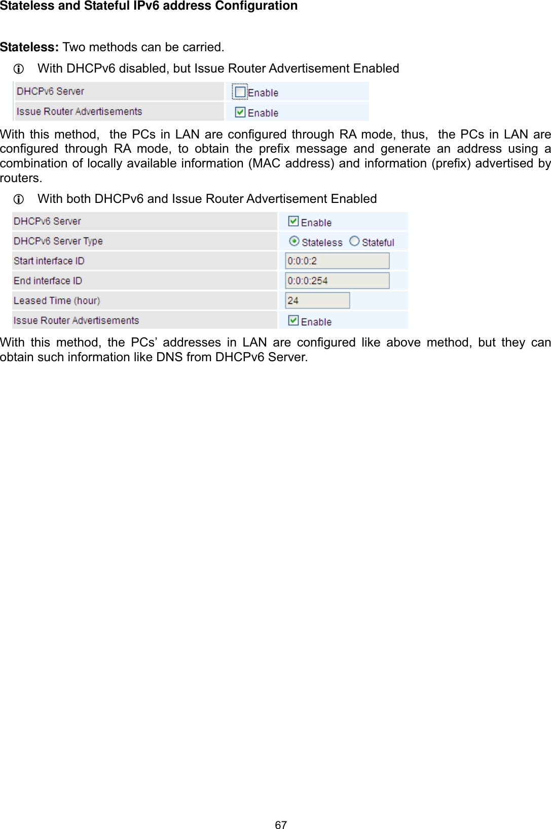
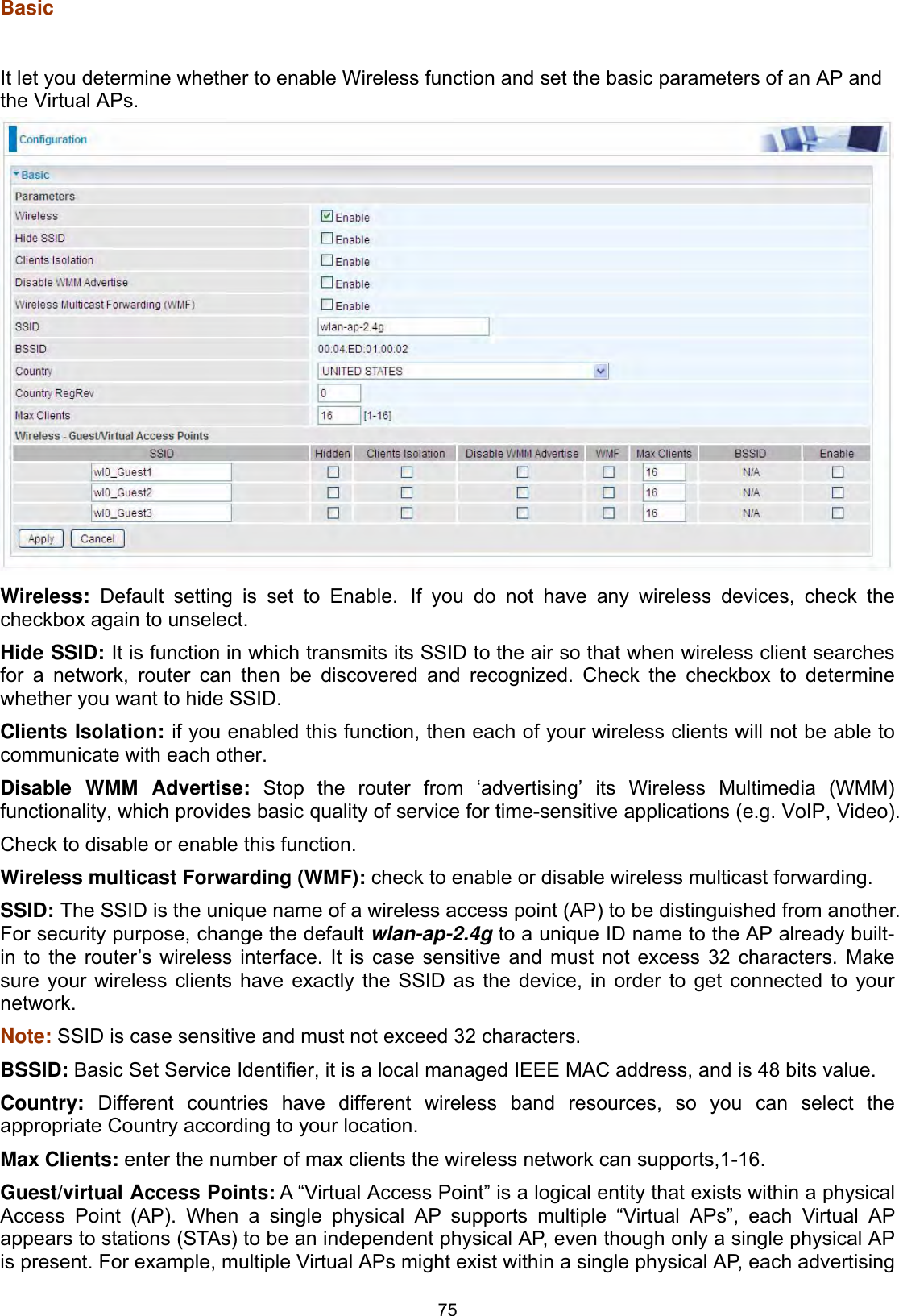
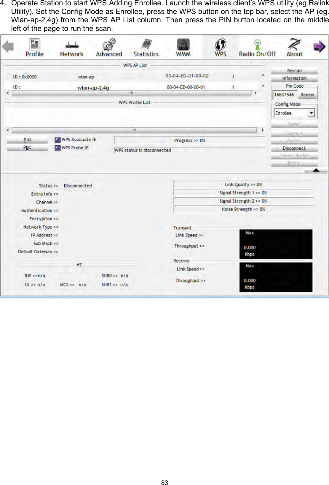
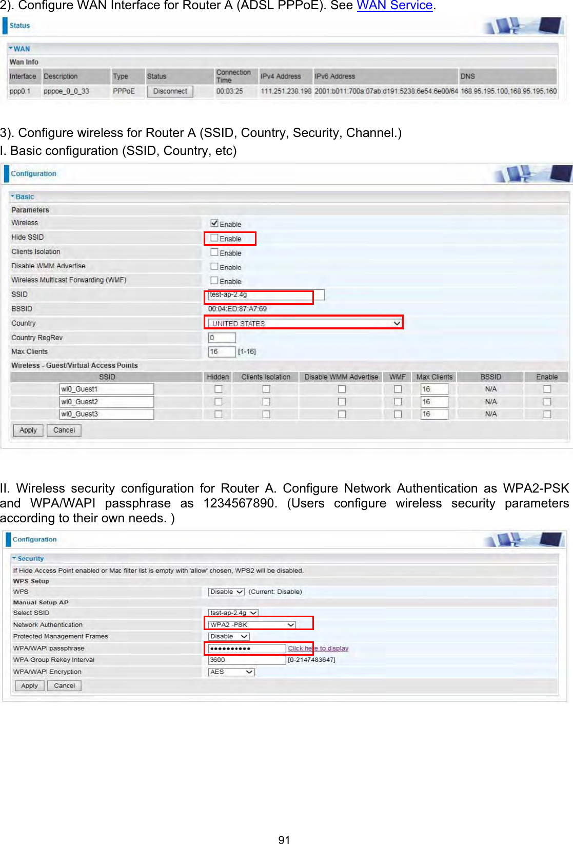
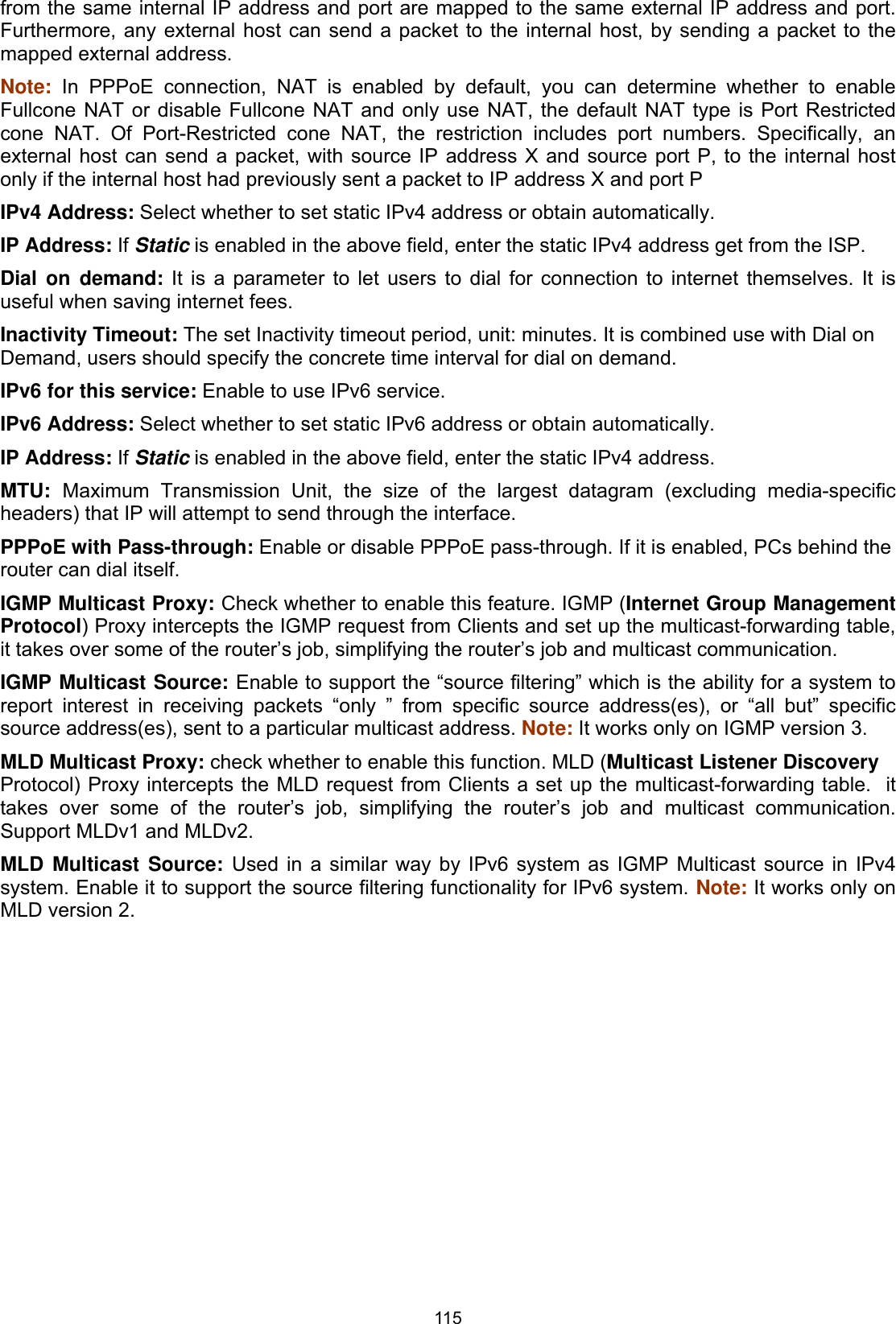
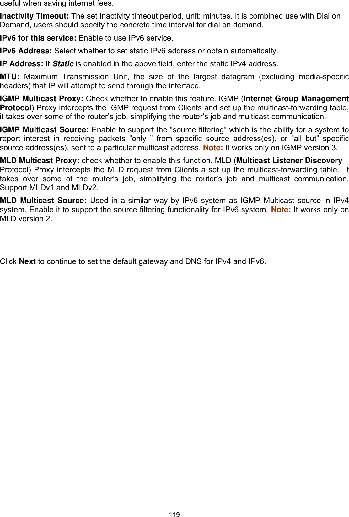
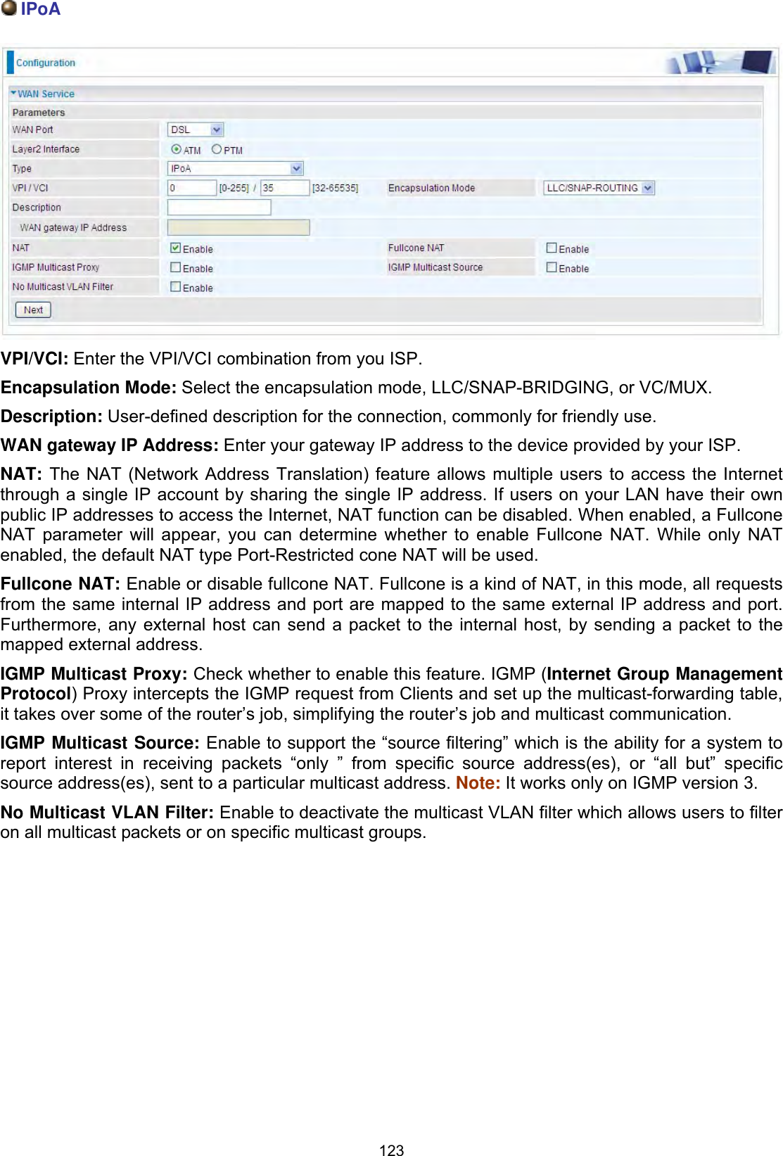
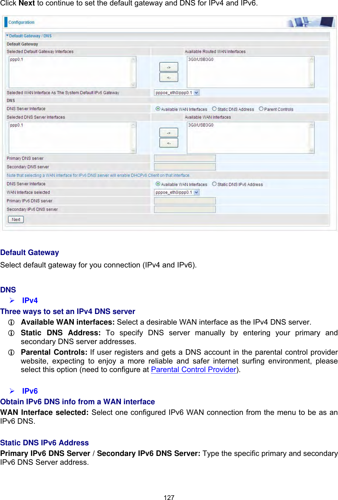
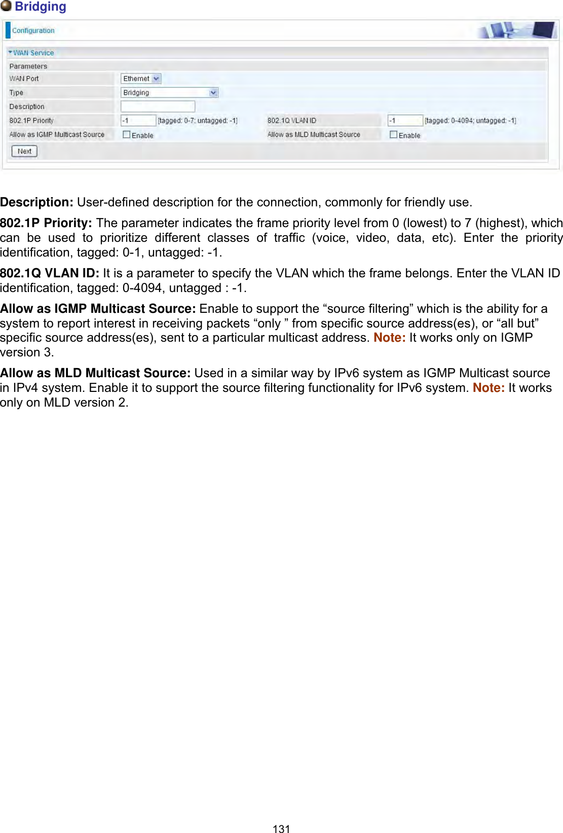
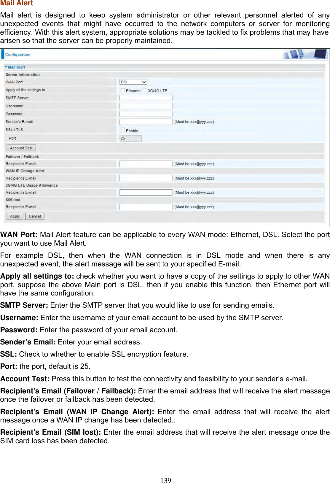
![161IP Filtering Incoming Incoming IP Filtering is set by default to block all incoming traffic, but user can set rules to forward the specific incoming traffic. Note:1. The maximum number of entries: 32. 2. When LAN side firewall or firewall in WAN interface(s) is enabled, user can move here to add allowing rules to pass through the firewall. Click Add button to enter the exact rule setting page. Filter Name: A user-defined rule name. User can select simply from the list box for the application for quick setup.IP Version: Select the IP Version, IPv4 or IPv6. Protocol: Set the traffic type (TCP/UDP, TCP, UDP, ICMP, RAW, Any ) that the rule applies to.Source IP address: This is the Address-Filter used to allow or block traffic to/from particular IP address(es) featured in the IP range.. If you leave empty, it means any IP address. Source Port [port or port:port]: The port or port range defines traffic from the port (specific application) or port in the set port range blocked to go through the router. Default is set port from range 1 – 65535.Destination IP address: Traffic from LAN with the particular traffic destination address specified in the IP range is to be blocked from going through the router, similarly set as the Source IP address above.Destination Port [port or port : port]: Traffic with the particular set destination port or port in the set port range is to be blocked from going through the router. Default is set port from port range: 1 – 65535Interfaces: Check if the filter rule applies to all interfaces. User can base on need select interfaces to make the rule take effect with those interfaces.](https://usermanual.wiki/Billion-Electric/BIL-8700AXL.User-Manual-Part-1/User-Guide-3810626-Page-166.png)