Billion Electric BIL-8700AXL Triple-WAN Wireless 1600 Mbps VPN VDSL2/ADSL2+ Firewall Router User Manual Part 2
Billion Electric Co., Ltd. Triple-WAN Wireless 1600 Mbps VPN VDSL2/ADSL2+ Firewall Router Part 2
Contents
- 1. User Manual Part 1
- 2. User Manual Part 2
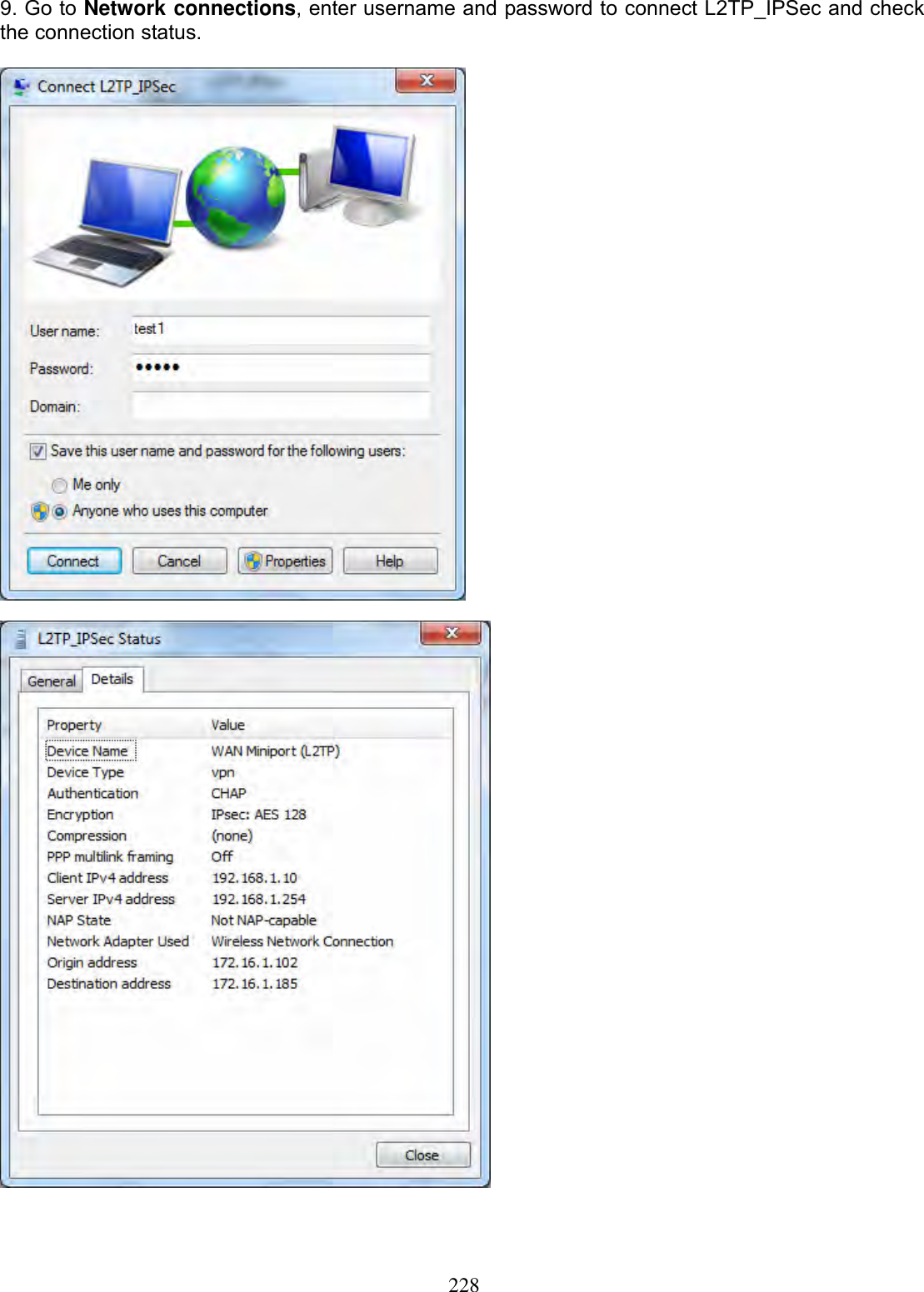
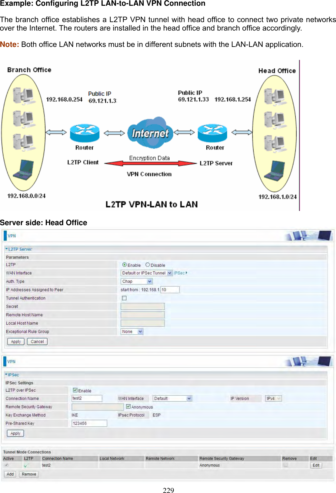
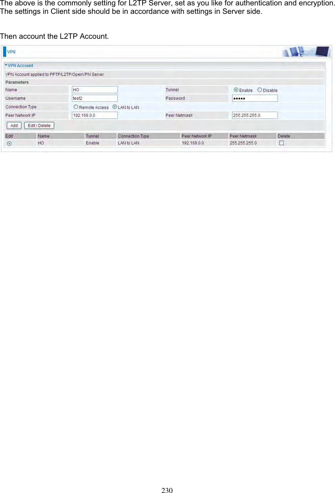
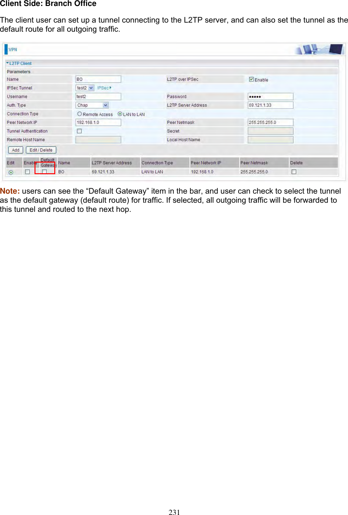
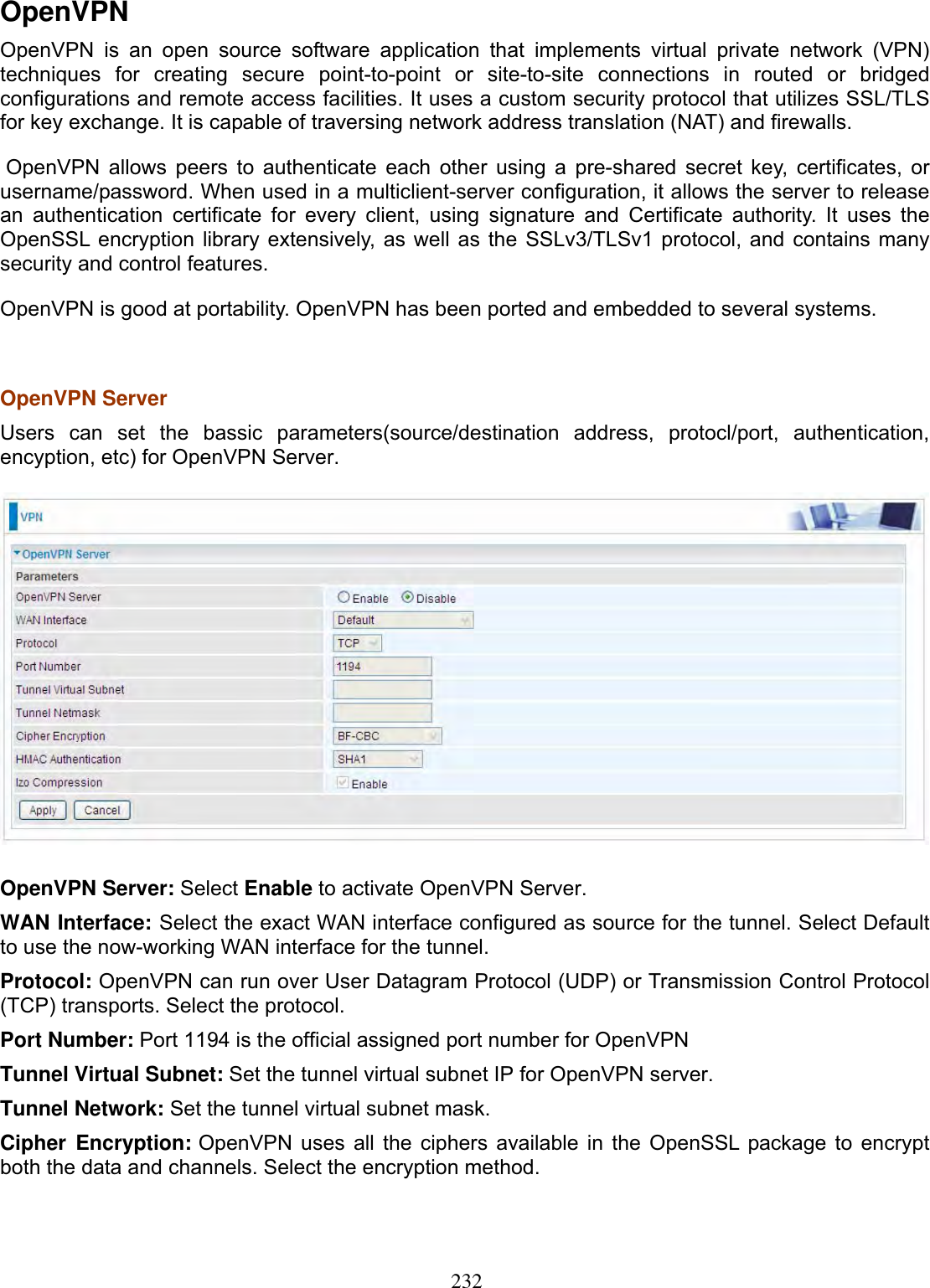
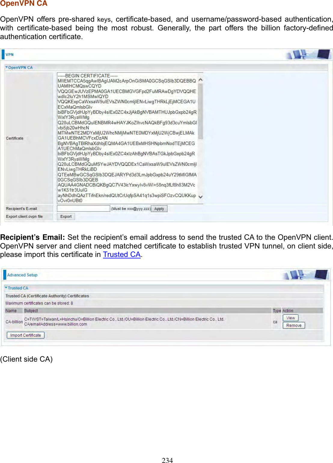
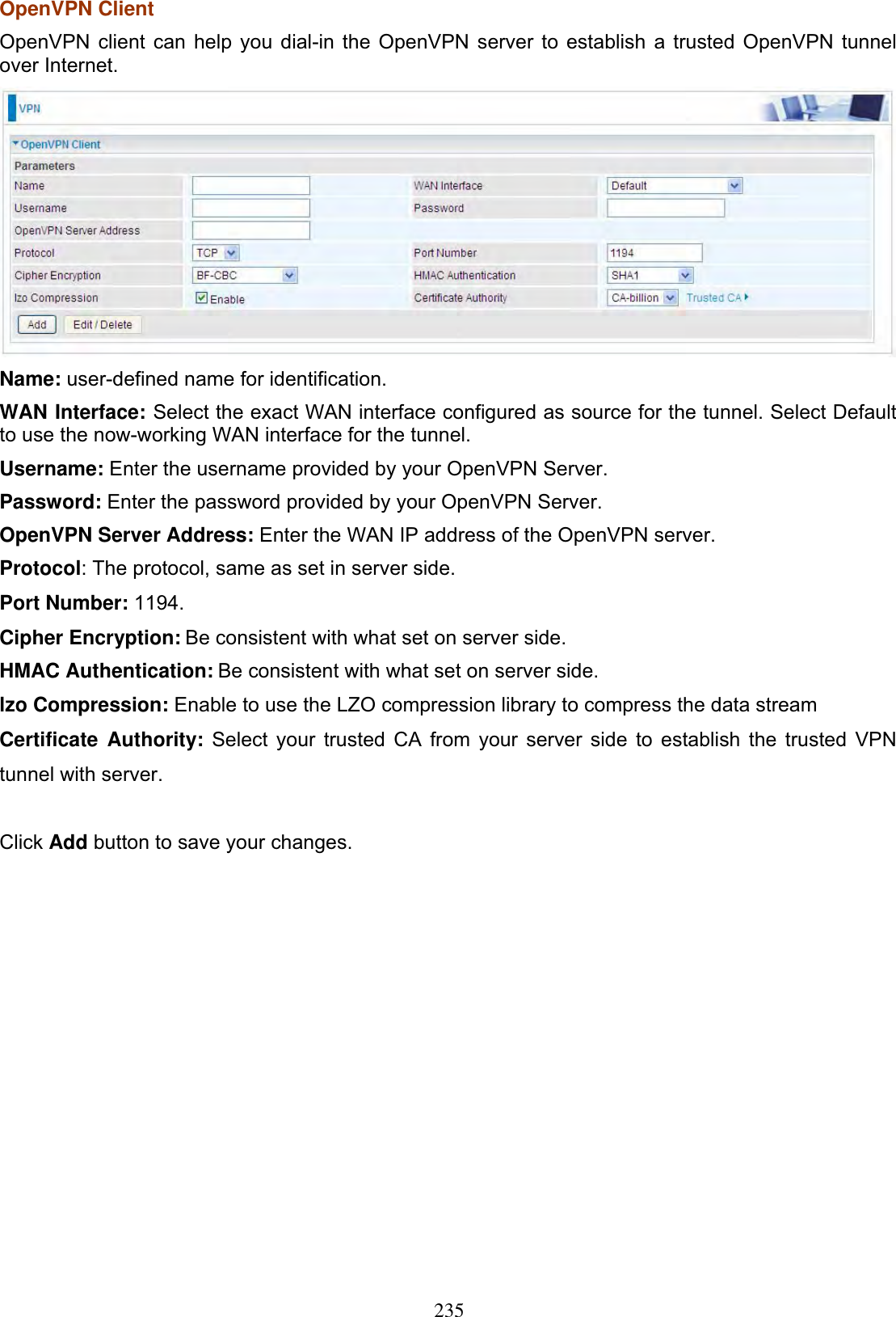
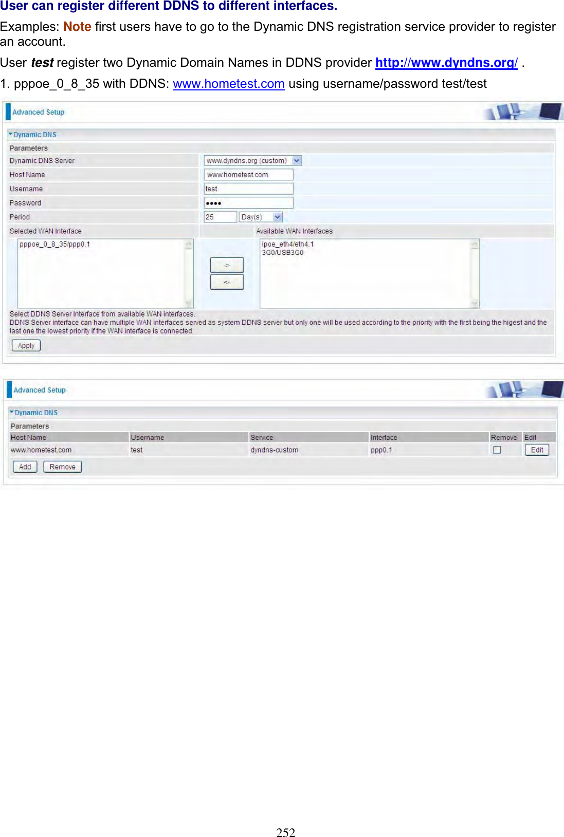
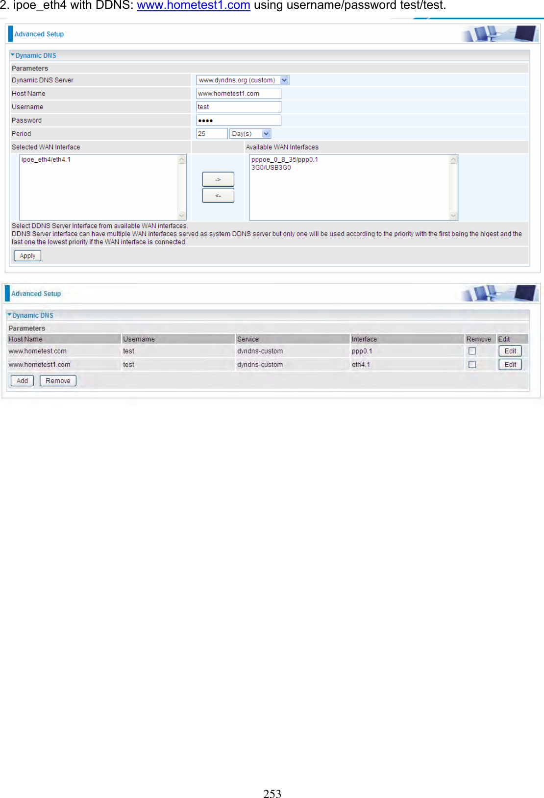
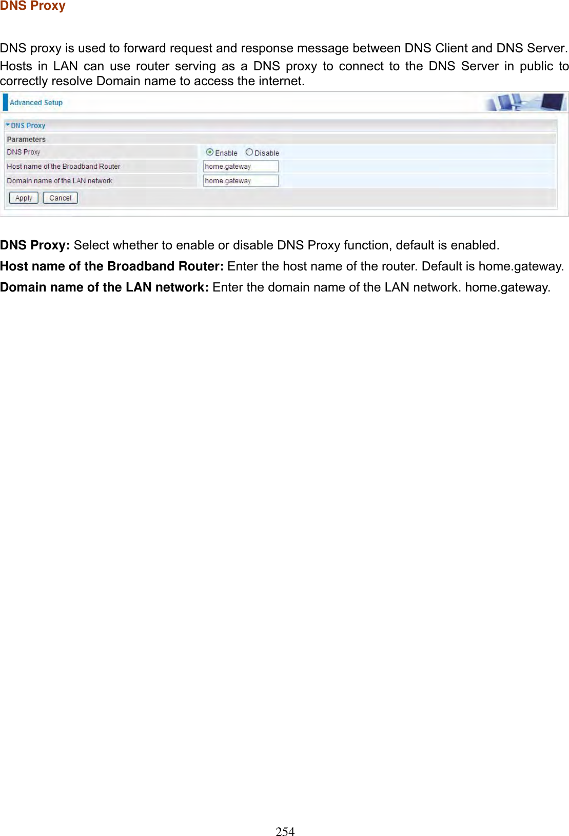
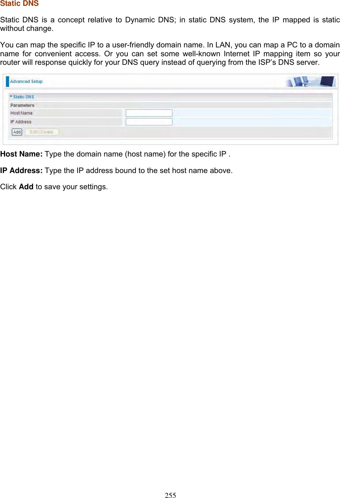
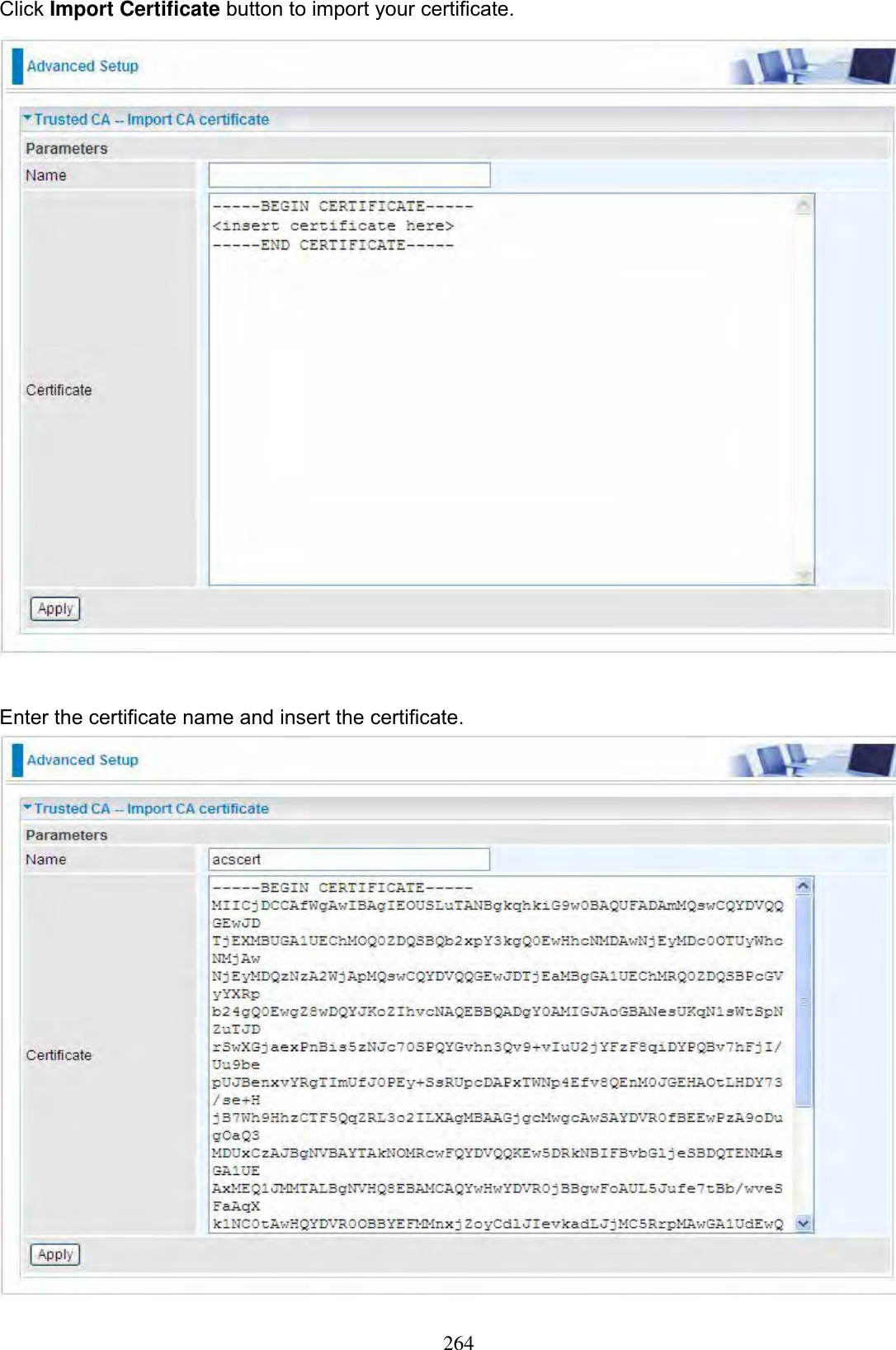
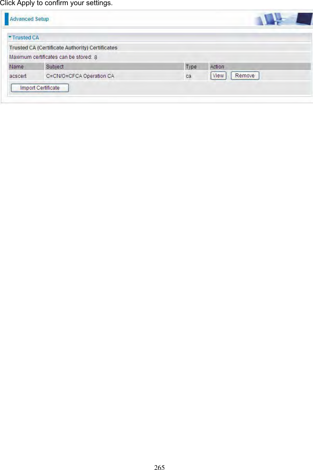
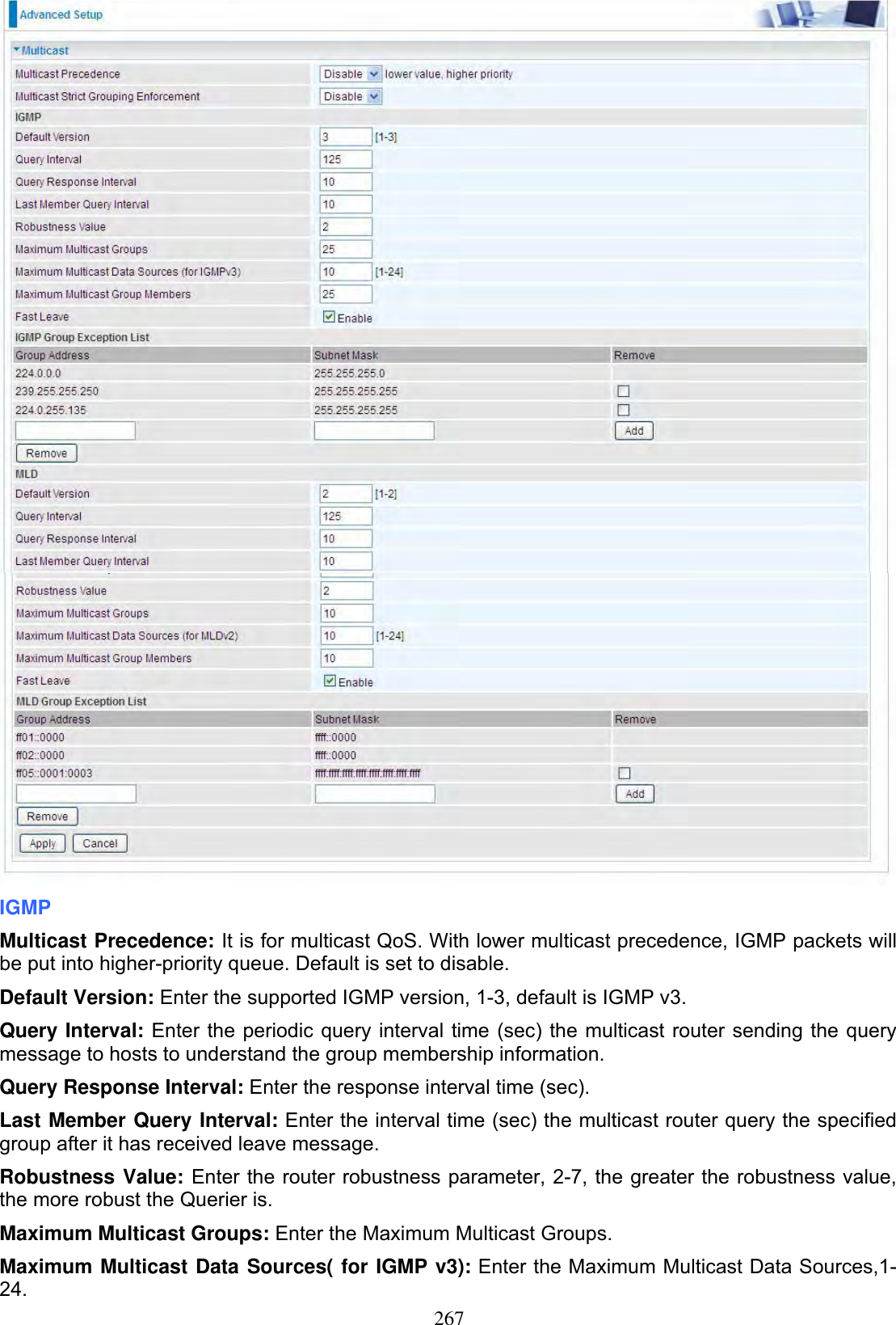
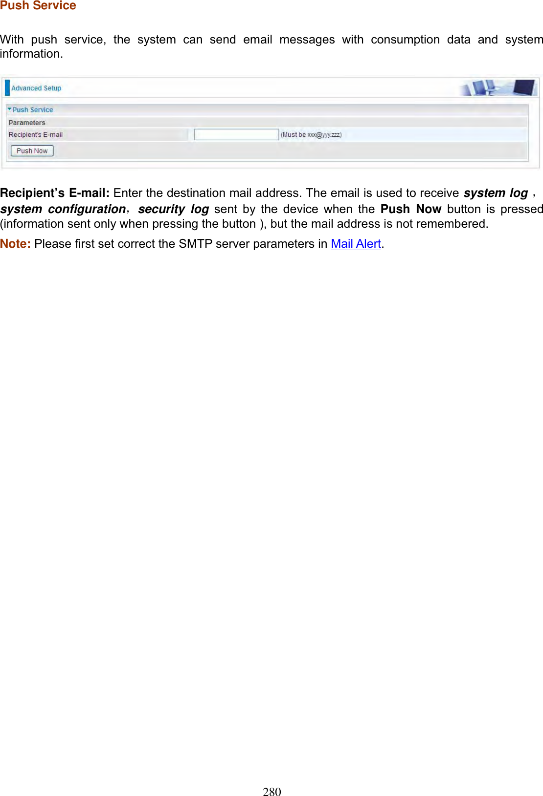
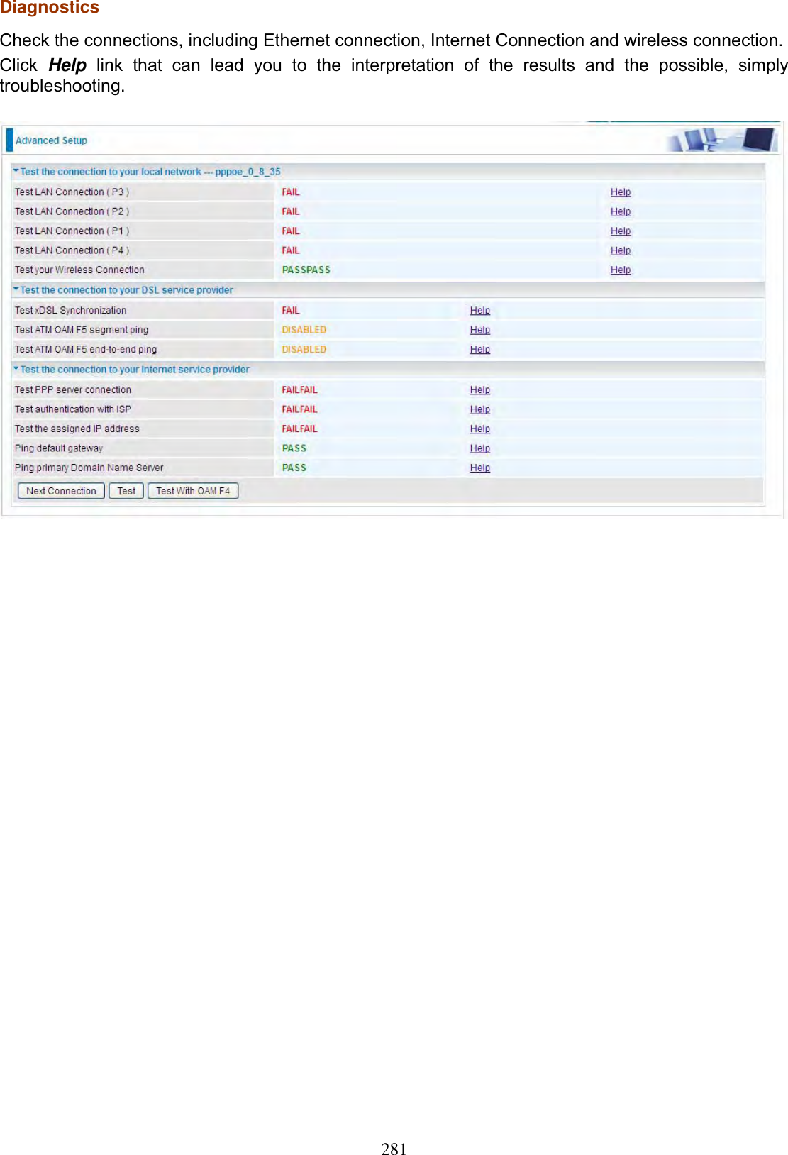
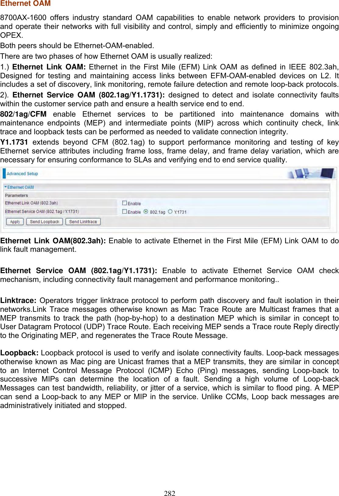
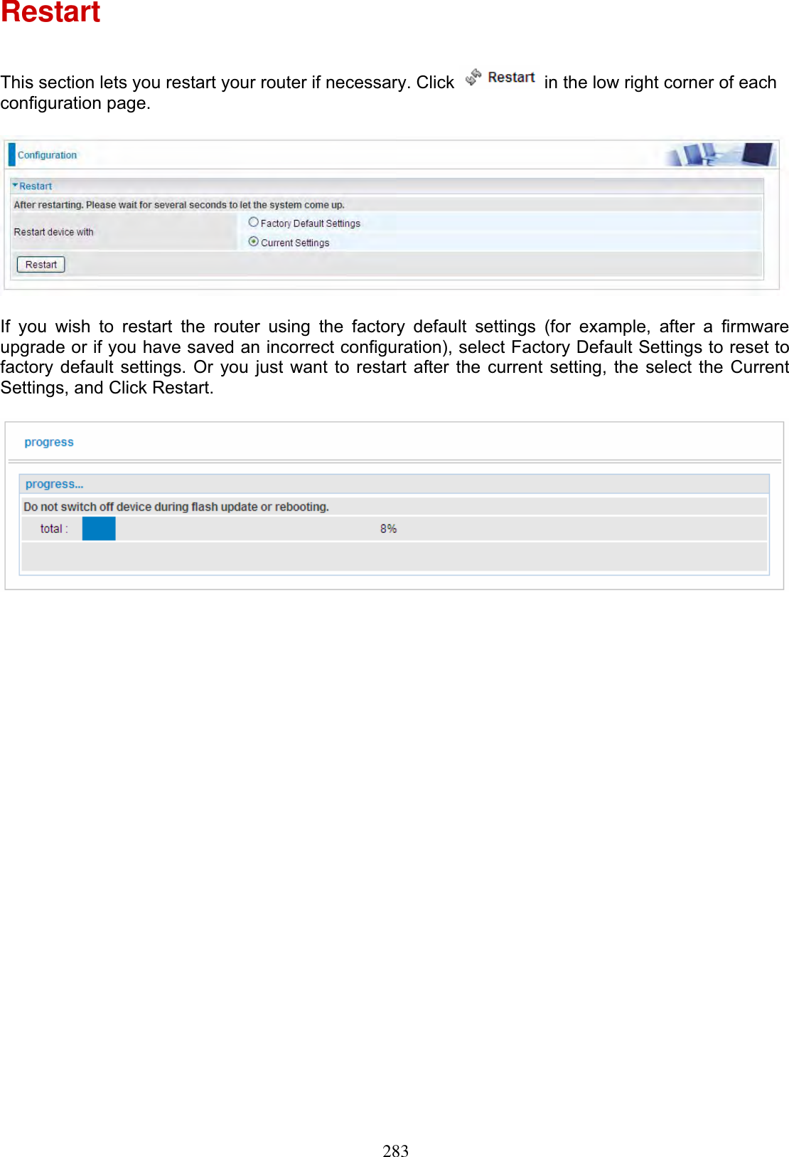
User Manual Part 2