Billion Electric BIL-8700AXL Triple-WAN Wireless 1600 Mbps VPN VDSL2/ADSL2+ Firewall Router User Manual Part 2
Billion Electric Co., Ltd. Triple-WAN Wireless 1600 Mbps VPN VDSL2/ADSL2+ Firewall Router Part 2
Contents
- 1. User Manual Part 1
- 2. User Manual Part 2
User Manual Part 2
196
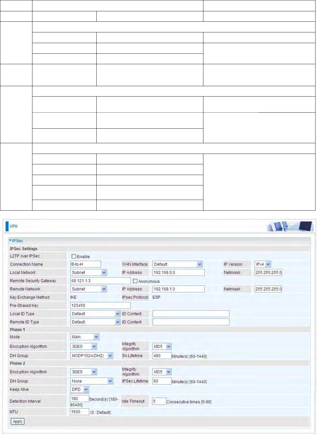
Branch Office Side:
Setup details: the same operation as done in Head Office side
Item Function Description
1Connection Name B-to-H Give a name for IPSec connection
Local Network
Subnet Select Subnet
IP Address 192.168.0.0
2
Netmask 255.255.255.0 Branch Office network
3
Remote Secure
Gateway
Address(Hostanme)
69.121.1.3 IP address of the Head office router
(on WAN side)
Remote Network
Subnet Select Subnet
IP Address 192.168.1.0
4
Netmask 255.255.255.0
Head office network
Proposal
Method ESP
Authentication MD5
Encryption 3DES
Prefer Forward
Security MODP 1024(group2)
5
Pre-shared Key 123456
Security Plan
197
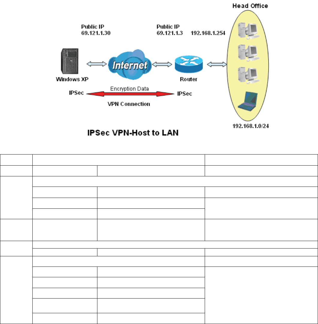
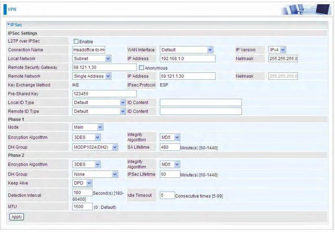
1. Host to LAN
Router servers as VPN server, and host should install the IPSec client to connect to head office
through IPSec VPN.
Item Function
Description
1 Connection Name
Headoffice-to-Host Give a name for IPSec connection
Local Network
Subnet Select Subnet
IP Address 192.168.1.0
2
Netmask 255.255.255.0 Head Office network
3
Remote Secure
Gateway
(Hostanme)
69.121.1.30 IP address of the Branch office router
(on WAN side)
Remote Network
4Single Address 69.121.1.30 Host
Proposal
Method ESP
Authentication MD5
Encryption 3DES
Prefer Forward
Security MODP 1024(group2)
5
Pre-shared Key 123456
Security Plan
198
199
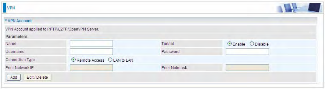
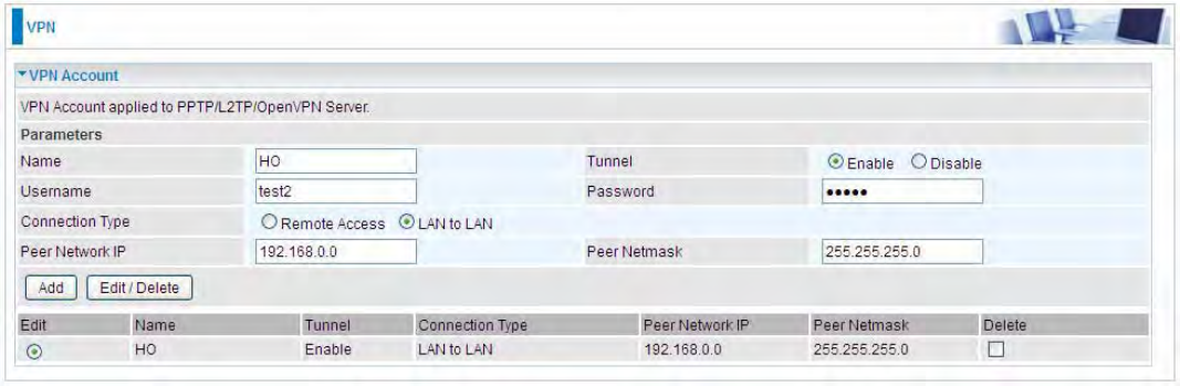
VPN Account
PPTP L2TP and OpenVPN server share the same account database set in VPN Account page.
Name: A user-defined name for the connection.
Tunnel: Select Enable to activate the account. PPTP(L2TP/OpenVPN) server is waiting for the
client to connect to this account.
Username: Please input the username for this account.
Password: Please input the password for this account.
Connection Type: Select Remote Access for single user, Select LAN to LAN for remote gateway.
Peer Network IP: Please input the subnet IP for remote network.
Peer Netmask: Please input the Netmask for remote network.
200
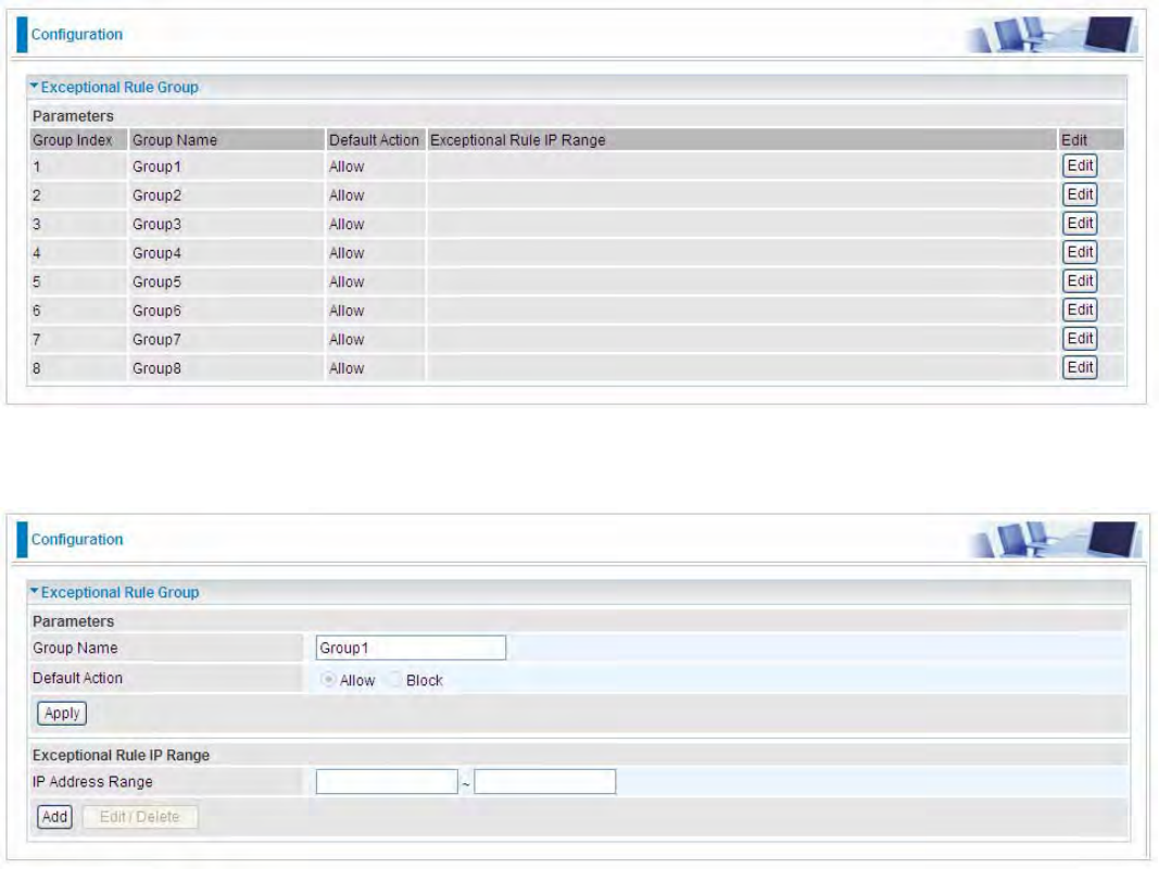
Exceptional Rule Group
Exceptional Rule is dedicated to giving or blocking PPTP/L2TP server access to some specific IP or
IPs(range). Users are allowed to set 8 different exceptional rule groups at most. In each group, user
can add specific IP or IP range.
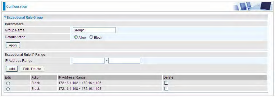
Press Edit to set the exceptional IP (IP Range).
Default Action: Please first set the range to make “Default Action” setting available.Set “Allow” to
ban the listed IP or IPs to access the PPTP and L2TP server.
Check “Block” to grant access to the listed IP or IPs to the PPTP and L2TP server.
Apply: Press Apply button to apply the change.
201
Exceptional Rule Range
IP Address Range: Specify the IP address range; IPv4 address range can be supported.
Click Add to add the IP Range.
For instance, if user wants to block IP range of 172.16.1.102-172.16.1.106 from accessing your
PPTP and L2TP server, you can add this IP range and valid it.
202
PPTP
The Point-to-Point Tunneling Protocol (PPTP) is a Layer2 tunneling protocol for implementing
virtual private networks through IP network. PPTP uses an enhanced GRE (Generic Routing
Encapsulation) mechanism to provide a flow- and congestion-controlled encapsulated datagram
service for carrying PPP packets.
In the Microsoft implementation, the tunneled PPP traffic can be authenticated with PAP, CHAP,
Microsoft CHAP V1/V2 or EAP-TLS. The PPP payload is encrypted using Microsoft Point-to-Point
Encryption (MPPE) when using MSCHAPv1/v2 or EAP-TLS.
Note: 4 sessions for Client and 4 sessions for Server respectively.
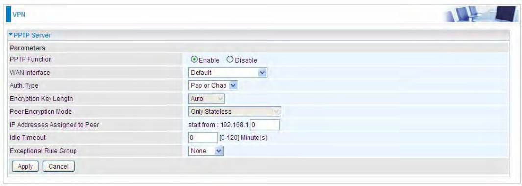
PPTP Server
In PPTP session, users can set the basaic parameters(authentication, encyption, peer address, etc)
for PPTP Server, and accounts in the next page of PPTP Account. They both constitutes the PPTP
Server setting.
PPTP Funtion: Select Enable to activate PPTP Server. Disable to deactivate PPTP Server function.
WAN Interface: Select the exact WAN interface configured for the tunnel. Select Default to use the
now-working WAN interface for the tunnel.
Auth. Type: The authentication type, Pap or Chap, PaP, Chap and MS-CHAPv2. When using PAP,
the password is sent unencrypted, whilst CHAP encrypts the password before sending, and also
allows for challenges at different periods to ensure that an intruder has not replaced the client. When
passed the authentication with MS-CHAPv2, the MPPE encryption is supported.
Encryption Key Length: The data can be encrypted by MPPE algorithm with 40 bits or 128 bits.
Default is Auto, it is negotiated when establishing a connection. 128 bit keys provide stronger
encryption than 40 bit keys.
Peer Encryption Mode: You may select “Only Stateless” or “Allow Stateless and Stateful” mode.
The key will be changed every packet when you select Stateless mode.
IP Addresses Assigned to Peer: 192.168.1.x: please input the IP assigned range from 1~ 254.
Idle Timeout: Specify the time for remote peer to be disconnected without any activities, from 0~120
203
minutes.
Exceptional Rule Group: Select to grant or block access to a group of IPs to the PPTP server. See
Exceptional Rule Group. If there is not any restriction, select none.
Click Apply to submit your PPTP Server basic settings.
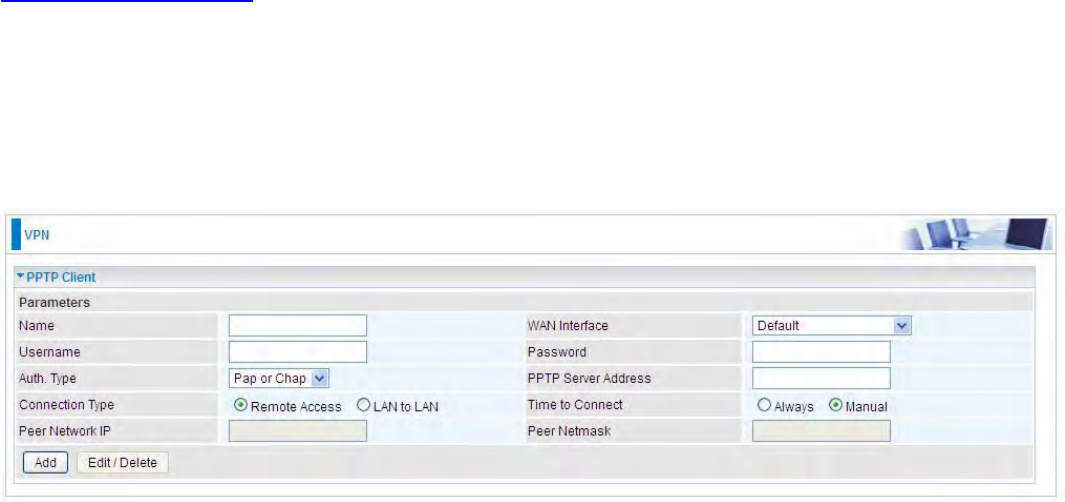
PPTP Client
PPTP client can help you dial-in the PPTP server to establish PPTP tunnel over Internet.
Name: user-defined name for identification.
WAN Interface: Select the exact WAN interface configured for the tunnel. Select Default to use the
now-working WAN interface for the tunnel.
Username: Enter the username provided by your VPN Server.
Password: Enter the password provided by your VPN Server.
Auth. Type: Default is Auto if you want the router to determine the authentication type to use, or
else manually specify CHAP (Challenge Handshake Authentication Protocol) or PAP (Password
Authentication Protocol) if you know which type the server is using (when acting as a client), or else
the authentication type you want clients connecting to you to use (when acting as a server). When
using PAP, the password is sent unencrypted, whilst CHAP encrypts the password before sending,
and also allows for challenges at different periods to ensure that an intruder has not replaced the
client.
PPTP Server Address: Enter the IP address of the PPTP server.
Connection Type: Select Remote Access for single user, Select LAN to LAN for remote gateway.
Time to Connect: Select Always to keep the connection always on, or Manual to connect manually
any time.
Peer Network IP: Please input the subnet IP for Server peer.
Peer Netmask: Please input the Netmask for server peer.
Click Add button to save your changes.
204
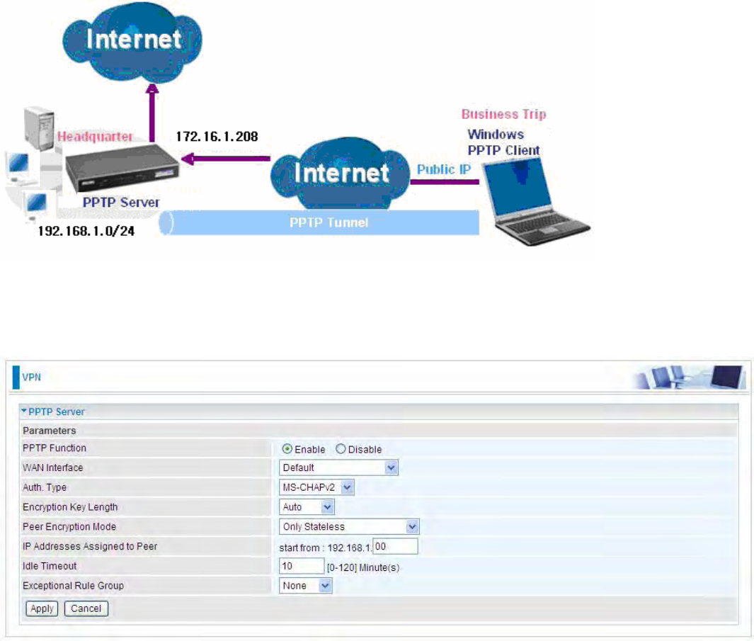
Example: PPTP Remote Access with Windows series
(Note: 1. inside test with 172.16.1.208, just an example for illustration
2. Here is a configuration example on Windows 7; Windows series including Windows 10/ 8/ 7 vista/
also supports the application with similar steps. )
Server Side:
1. Configuration >VPN >PPTP and Enable the PPTP function, Click Apply.

205
2. Create a PPTP Account “test”.
Client Side: Windows series
Note: Here is a configuration example on Windows 7; Windows series including Windows 10/ vista/
8/ 7 also supports the application with similar steps.
1. In Windows7, click Start >Control Panel>Network and Sharing Center, Click Set up a new
connection network.
(Windows7)

206
For Windows 10, Users can click Start > Settings; or right click the mouse when it points at
Windows ICON (Start), then click Control Panel >Network and Sharing Center, then Set up a
new connection network.
(Windows10)

207
2. Click Connect to a workplace, and press Next.
3. Select Use my Internet connection (VPN) and press Next.
4. Input Internet address and Destination name for this connection and press Next.
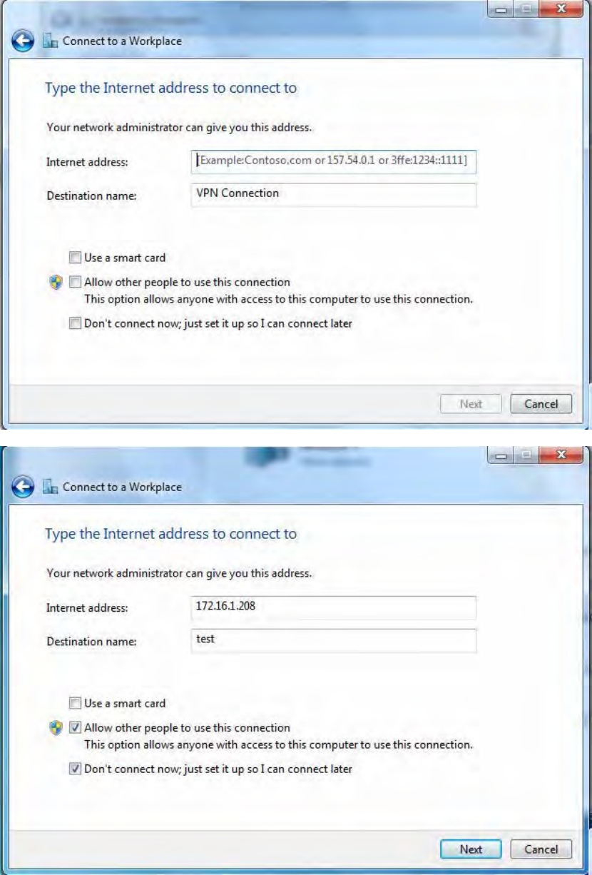
208
209
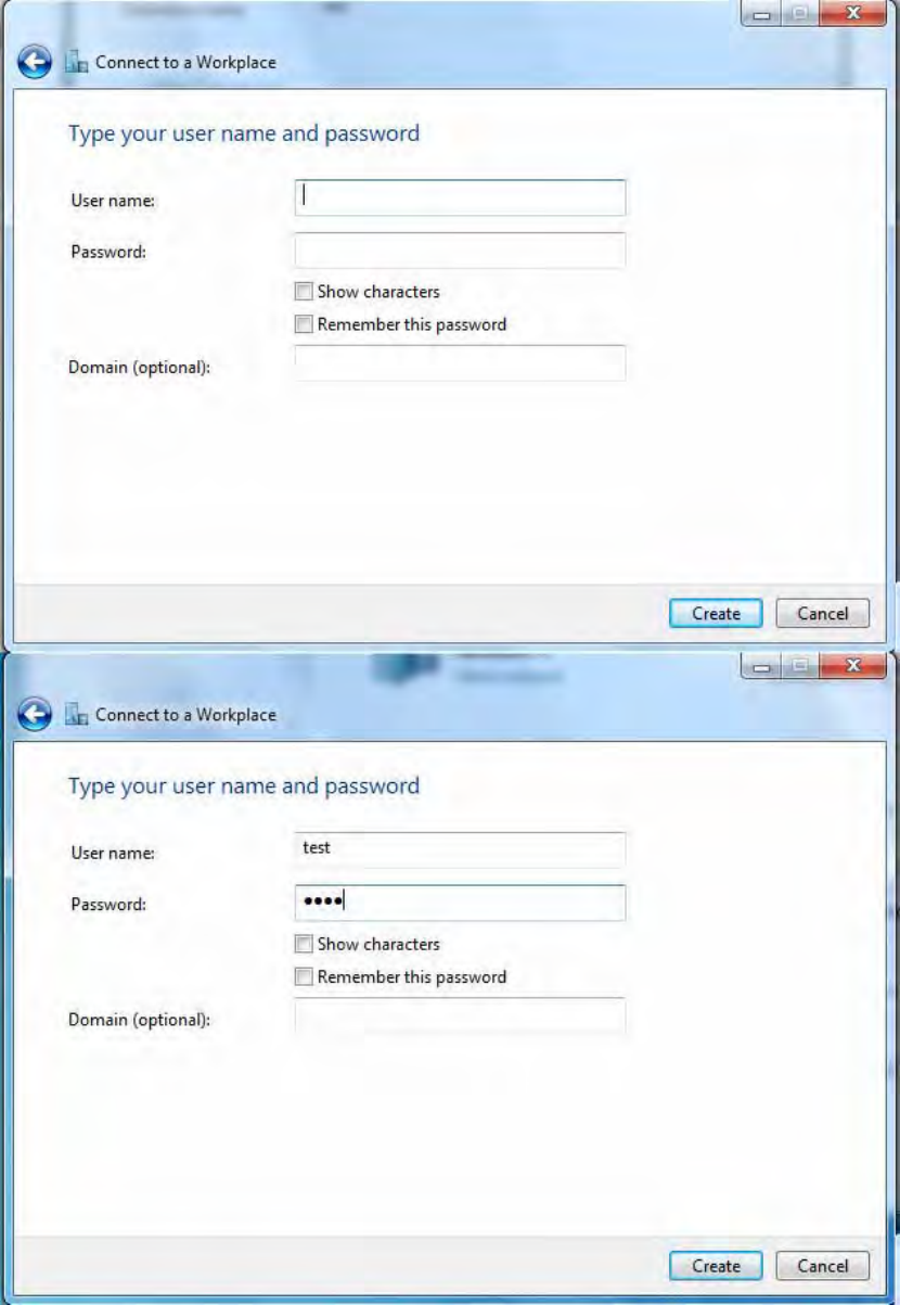
5. Input the account (user name and password) and press Create.
210
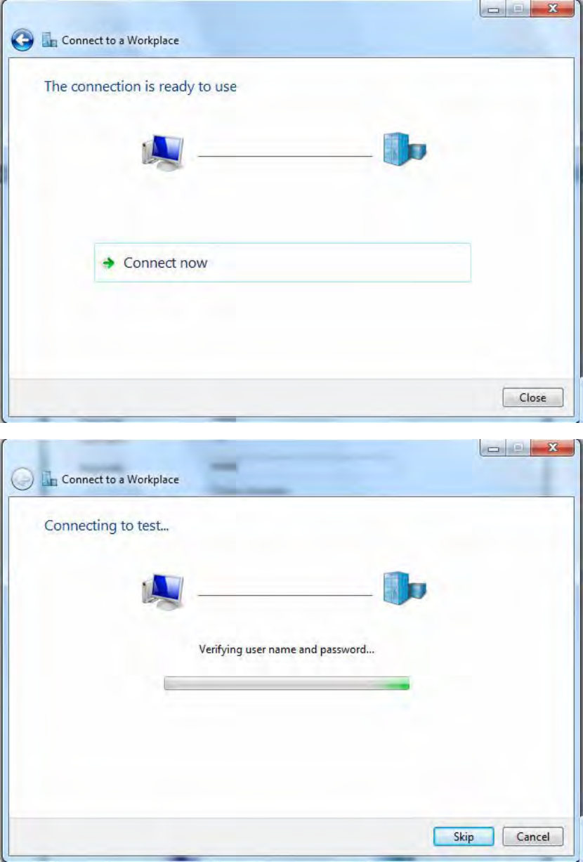
6. Connect to the server.
211
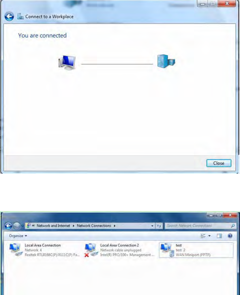
7. Successfully connected.
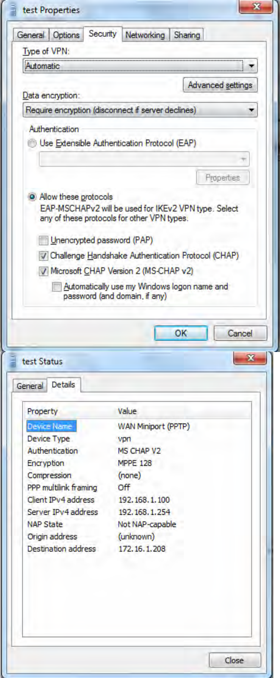
PS: You can also go to Network Connections shown below to check the detail of the connection.
Right click “test” icon, and select “Properties” to change the security parameters (if the connection
fails, users can go here to change the settings)
212
213
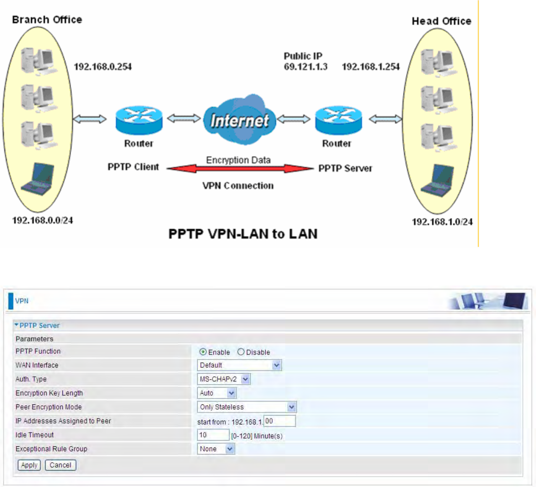
Example: Configuring a LAN-to-LAN PPTP VPN Connection
The branch office establishes a PPTP VPN tunnel with head office to connect two private networks
over the Internet. The routers are installed in the head office and branch offices accordingly.
Server side: Head Office
The above is the common setting for PPTP Server, set as you like for authentication and encryption.
The settings in Client side should be in accordance with settings in Server side.
214
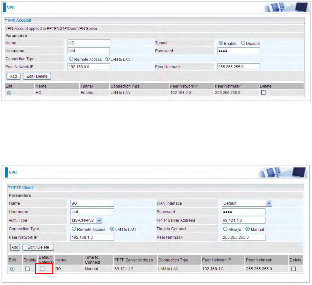
Then the PPTP Account.
Client Side: Branch Office
The client user can set up a tunnel connecting to the PPTP server, and can also set the tunnel as
the default route for all outgoing traffic.
Note: users can see the “Default Gateway” item in the bar, and user can check to select the tunnel
as the default gateway (default route) for traffic. If selected, all outgoing traffic will be forwarded to
this tunnel and routed to the next hop.
215
L2TP
The Layer 2 Tunneling Protocol (L2TP) is a Layer2 tunneling protocol for implementing virtual
private networks.
L2TP does not provide confidentiality or strong authentication by itself. IPsec is often used to secure
L2TP packets by providing confidentiality, authentication and integrity. The combination of these two
protocols is generally known as L2TP/IPsec.
In L2TP section, both pure L2TP and L2TP/IPSec are supported. Users can choose your preferable
option for your own needs.
Note: 4 sessions for Client and only one for Server respectively.
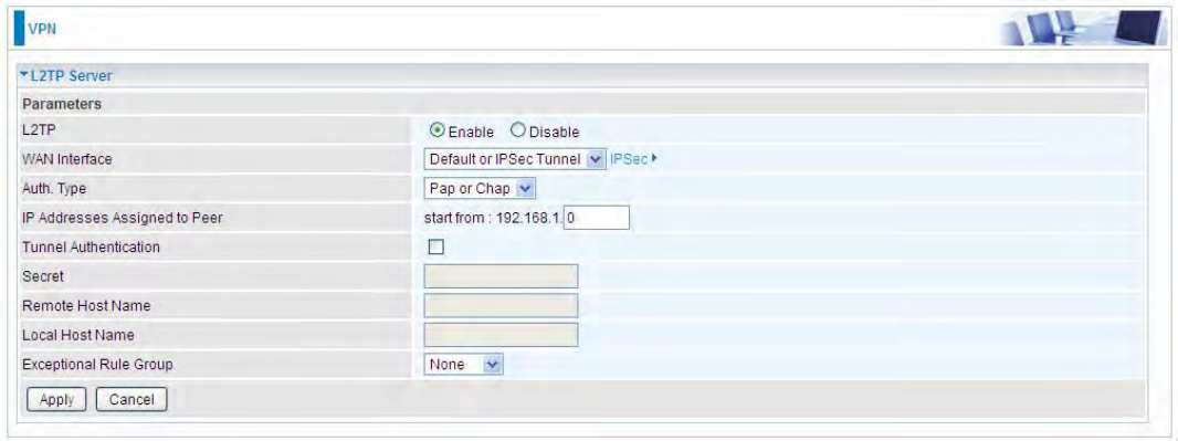
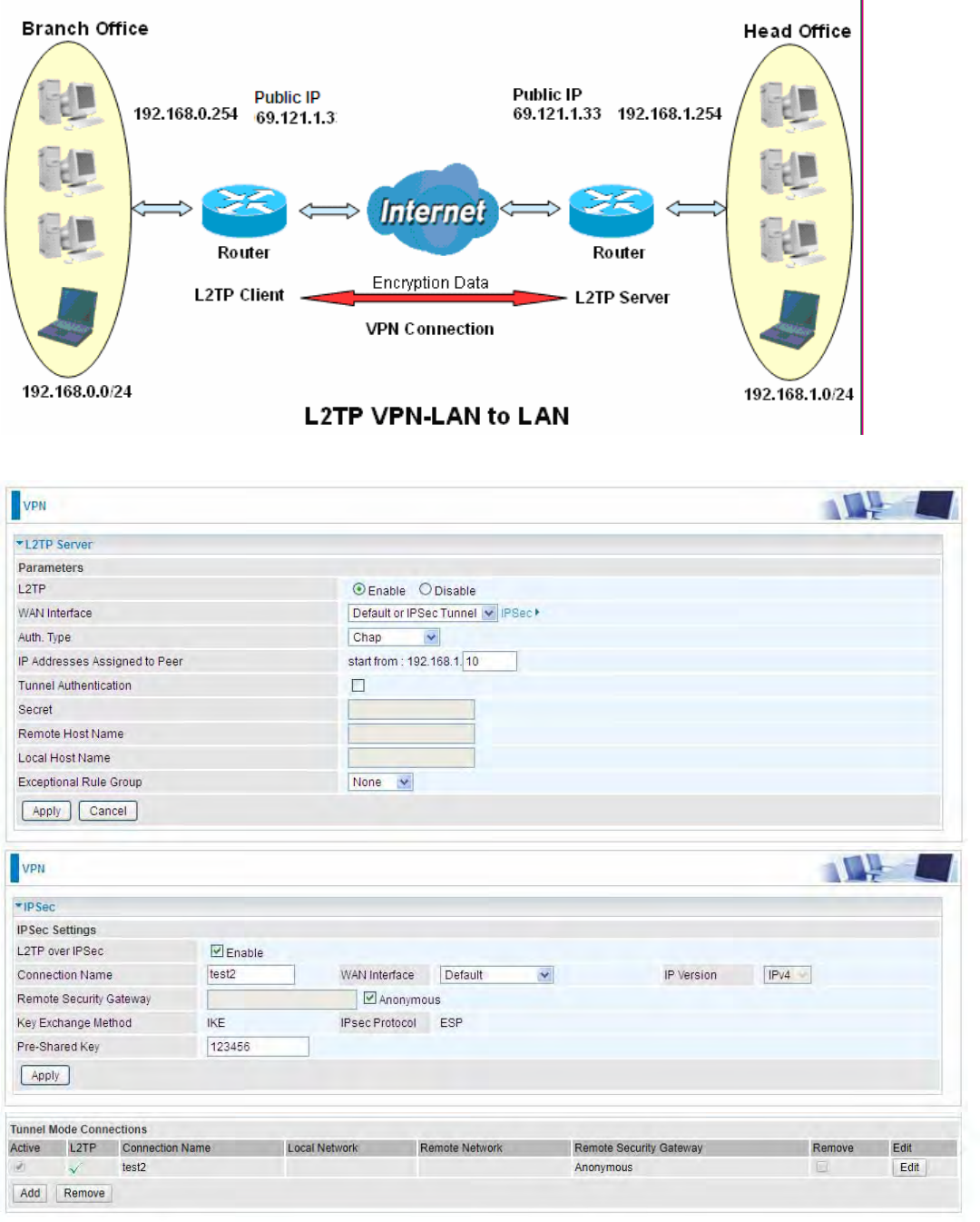
L2TP Server
In L2TP session, users can set the bassic parameters(authentication, encyption, peer address, etc)
for L2TP Server, and accounts in the page of VPN Account. They both constitutes the complete
L2TP Server settings.
L2TP: Select Enable to activate L2TP Server. Disable to deactivate L2TP Server.
WAN Interface: Select the exact WAN interface configured as source for the tunnel. Select different
interfaces, you will decide whether to use L2TP over IPSec or the pure L2TP.
LL2TP over IPSec, Select “Default or IPSec Tunnel” only when there is IPSec for L2TP rule in
place.
LPure L2TP, Select Default (there is no IPSec for L2TP in place) or other interface to activate
the pure L2TP.
Auth. Type: The authentication type, Pap or Chap, PaP, Chap. When using PAP, the password is
sent unencrypted, whilst CHAP encrypts the password before sending, and also allows for
challenges at different periods to ensure that an intruder has not replaced the client.
IP Addresses Assigned to Peer: 192.168.1.x: please input the IP assigned range from 1~ 254.
Tunnel Authentication: Select whether to enable L2TP tunnel authentication. Enable it if needed

216
and set the same in the client side.
Secret: Enter the secretly pre-shared password for tunnel authentication.
Remote Host Name: Enter the remote host name (of peer) featuring the destination of the L2TP
tunnel.
Local Host Name: Enter the local host name featuring the source of the L2TP tunnel.
Exceptional Rule Group: Select to grant or block access to a group of IPs to the L2TP server. See
Exceptional Rule Group. If there is not any restriction, select none.
Click Apply to submit your L2TP Server basic settings.
217
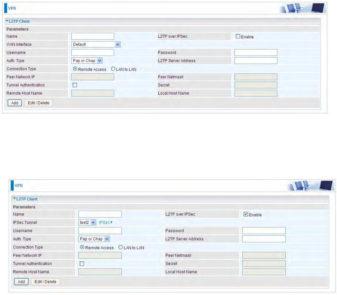
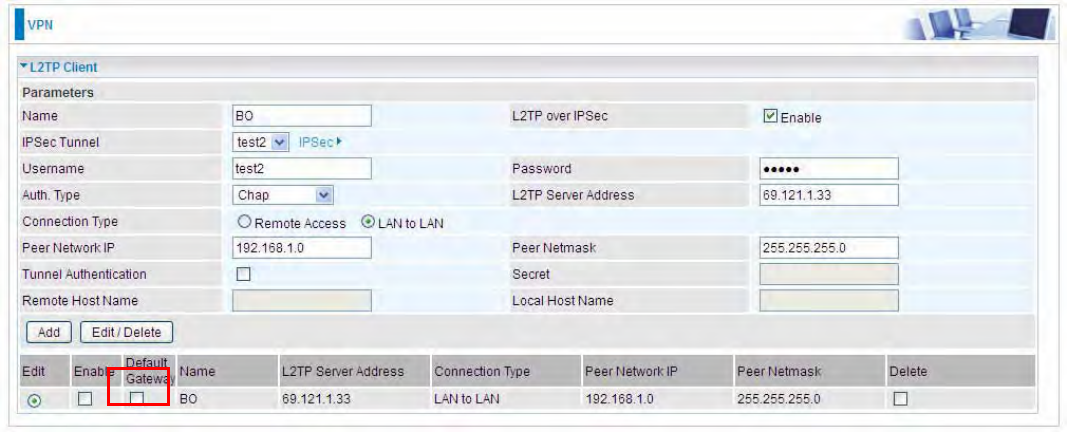
L2TP Client
L2TP client can help you dial-in the L2TP server to establish L2TP tunnel over Internet.
Name: user-defined name for identification.
L2TP over IPSec: If your L2TP server has used L2TP over IPSec feature, please enable this item.
under this circumstance, client and server communicate using L2TP over IPSec.
LEnable
IPSec Tunnel: Select the appropriate IPSec for L2TP rule configured for the L2TP Client.
Username: Enter the username provided by your L2TP Server.
Password: Enter the password provided by your L2TP Server.
Auth. Type: Default is Pap or CHap if you want the router to determine the authentication type to
use, or else manually specify CHAP (Challenge Handshake Authentication Protocol) or PAP
(Password Authentication Protocol) if you know which type the server is using. When using PAP, the
password is sent unencrypted, whilst CHAP encrypts the password before sending, and also allows
for challenges at different periods to ensure that an intruder has not replaced the client.
L2TP Server Address: Enter the IP address of the L2TP server.
218
Connection Type: Select Remote Access for single user, Select LAN to LAN for remote gateway.
Peer Network IP: Please input the subnet IP for Server.
Peer Netmask: Please input the Netmask for Server.
Tunnel Authentication: Select whether to enable L2TP tunnel authentication, if the server side
enables this feature, please follow.
Secret: Enter the set secret password in the server side.
Remote Host Name: Enter the remote host name featuring the destination of the L2TP tunnel.
Local Host Name: Enter the local host name featuring the source of the L2TP tunnel.
Click Add button to save your changes.
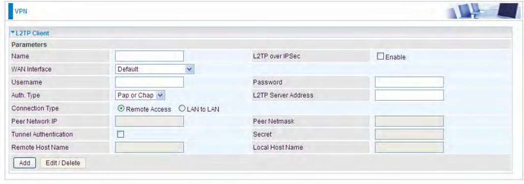
LDisable
WAN Interface: Select the exact WAN interface configured for the tunnel. Select Default to use the
now-working WAN interface for the tunnel. Under this circumstance, client and server communicate
through pure L2TP server.
Username: Enter the username provided by your L2TP Server.
Password: Enter the password provided by your L2TP Server.
Auth. Type: Default is Pap or CHap if you want the router to determine the authentication type to
use, or else manually specify CHAP (Challenge Handshake Authentication Protocol) or PAP
(Password Authentication Protocol) if you know which type the server is using. When using PAP, the
password is sent unencrypted, whilst CHAP encrypts the password before sending, and also allows
for challenges at different periods to ensure that an intruder has not replaced the client.
L2TP Server Address: Enter the IP address of the L2TP server.
Connection Type: Select Remote Access for single user, Select LAN to LAN for remote gateway.
Peer Network IP: Please input the subnet IP for Server.
Peer Netmask: Please input the Netmask for server.
Tunnel Authentication: Select whether to enable L2TP tunnel authentication, if the server side
enables this feature, please follow.
219
Secret: Enter the set secret password in the server side.
Remote Host Name: Enter the remote host name featuring the destination of the L2TP tunnel.
Local Host Name: Enter the local host name featuring the source of the L2TP tunnel.
Click Add button to save your changes.
220
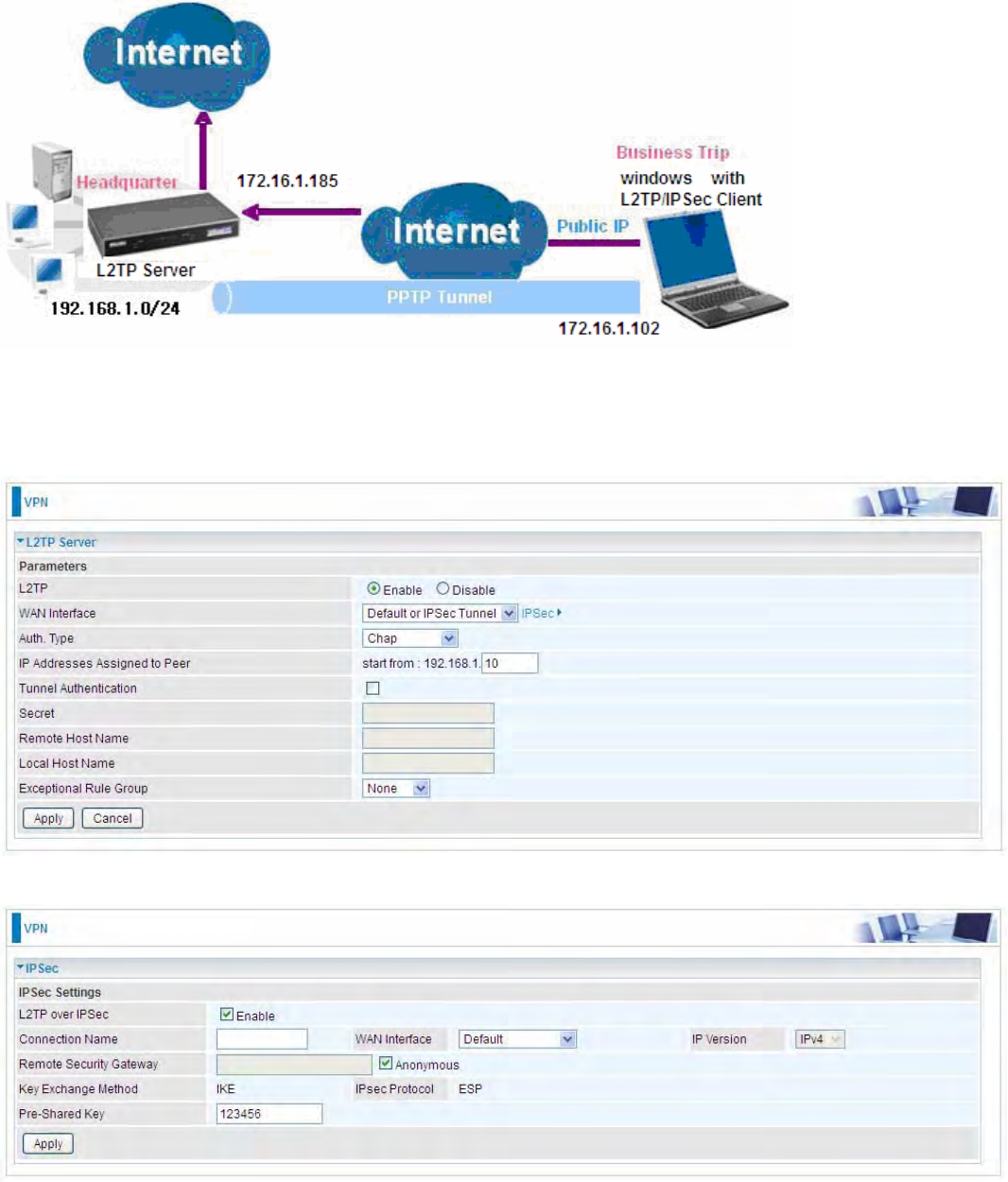
Example: L2TP over IPSec Remote Access with Windows series
(Note: 1. inside test with 172.16.1.185, just an example for illustration
2. Here is a configuration example on Windows 7; Windows series including Windows 10/ 8/ 7 vista/
also supports the application with similar steps. )
Server Side:
1. Configuration >VPN >L2TP and Enable the L2TP function, Click Apply.
The IPSec for L2TP rule
221
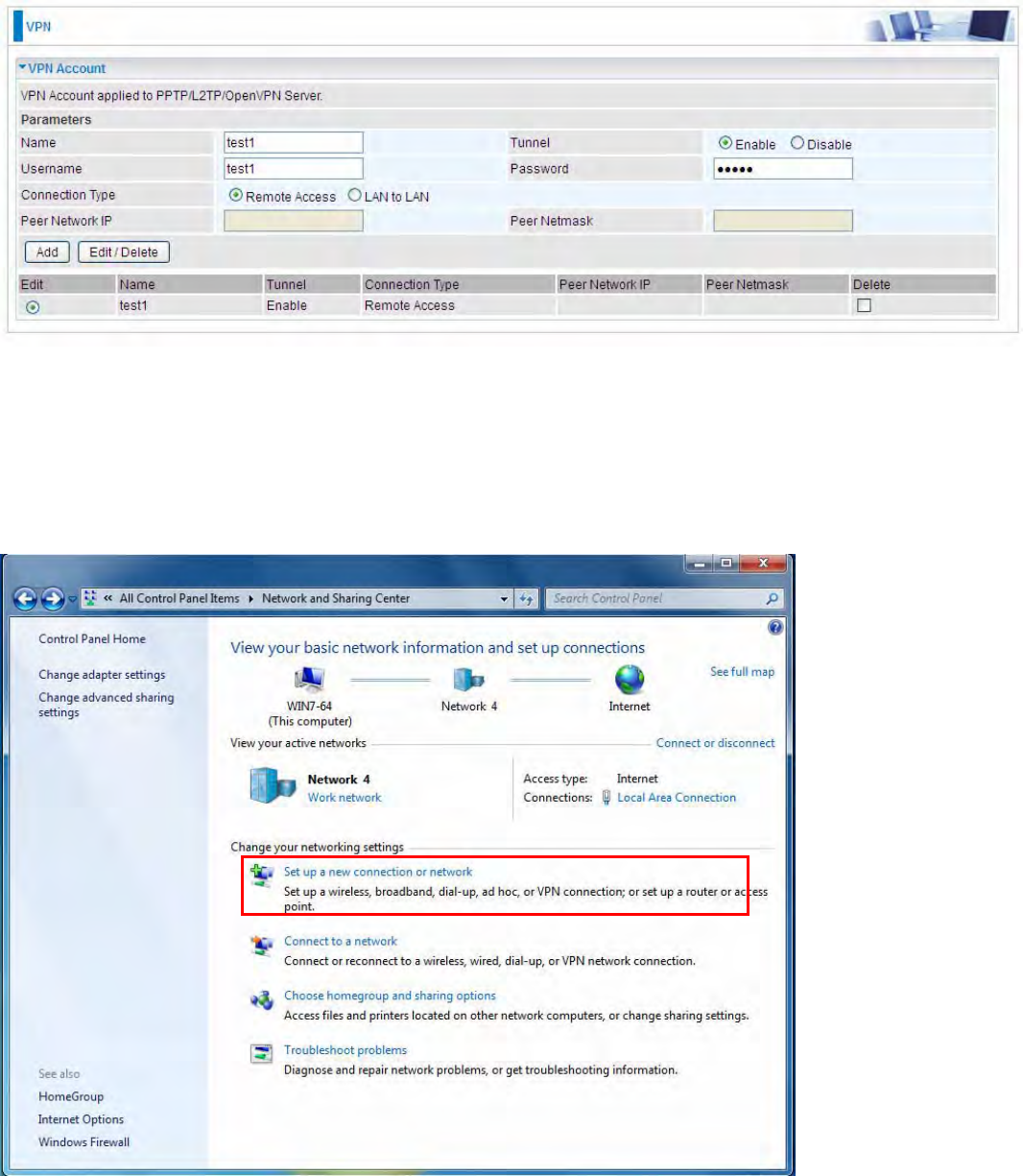
2. Create a L2TP Account “test1”.
Client Side: Windows series
Note: Here is a configuration example on Windows 7; Windows series including Windows 10/ vista/
8/ 7 also supports the application with similar steps.
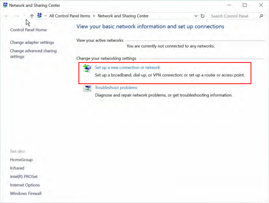
1. In Windows7, click Start >Control Panel>Network and Sharing Center, Click Set up a new
connection network.
(Windows7)
222
For Windows 10, Users can click Start > Settings; or right click the mouse when it points at
Windows ICON (Start), then click Control Panel >Network and Sharing Center, then Set up a
new connection network.
(Windows10)
223
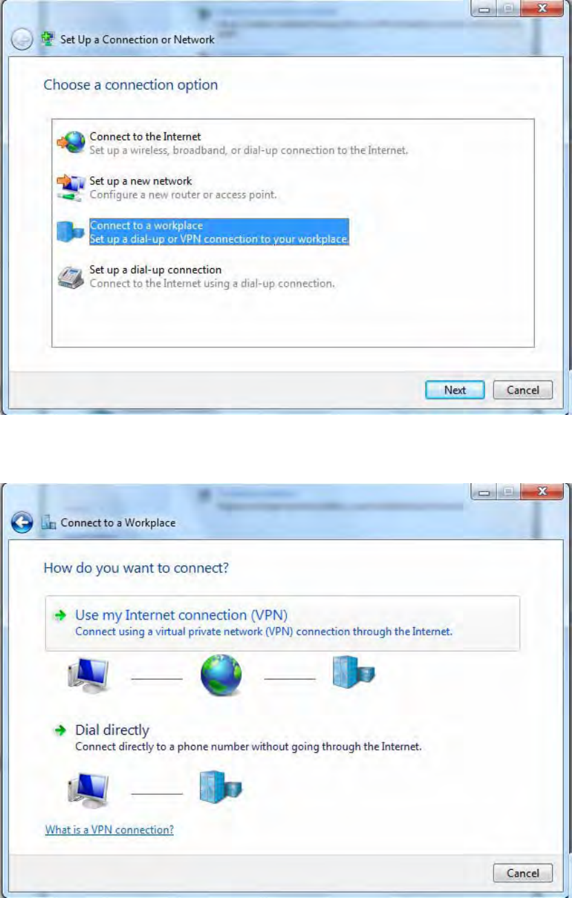
2. Click Connect to a workplace, and press Next.
3. Select Use my Internet connection (VPN) and press Next.
224
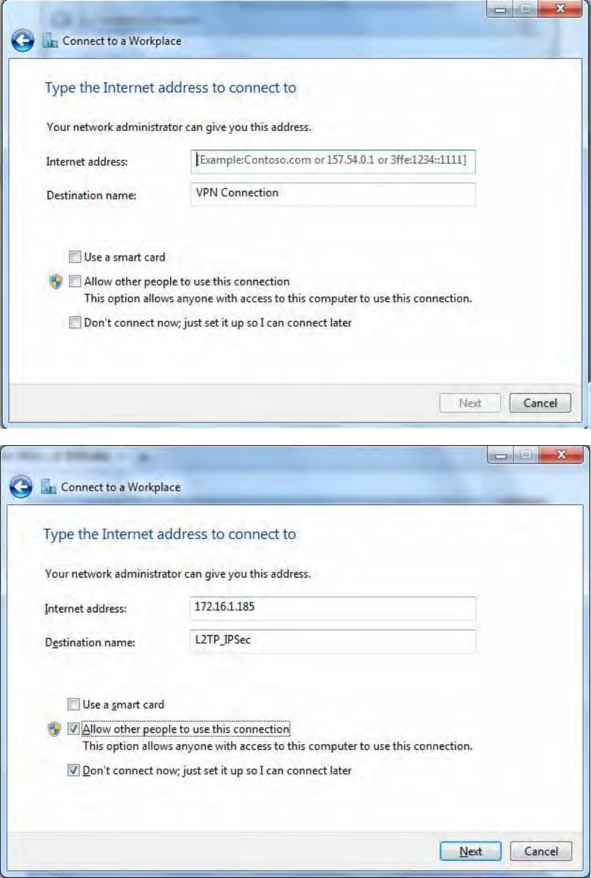
4. Input Internet address and Destination name for this connection and press Next.
225
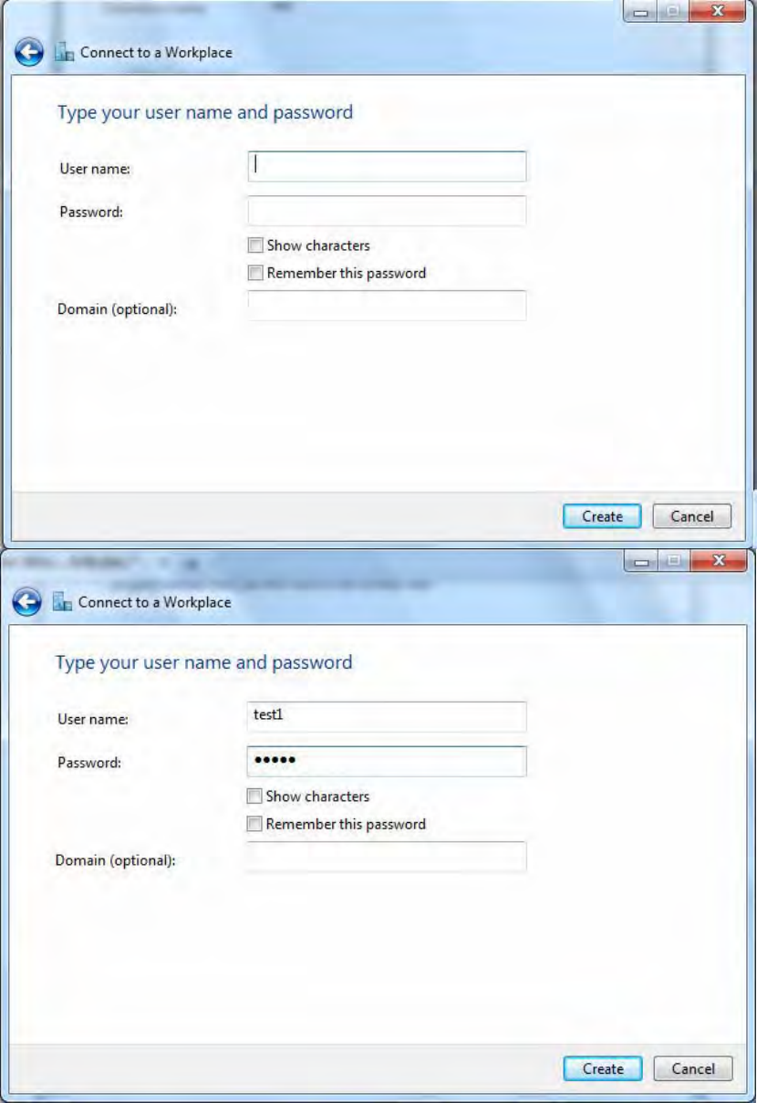
5. Input the account (user name and password) and press Create.
226
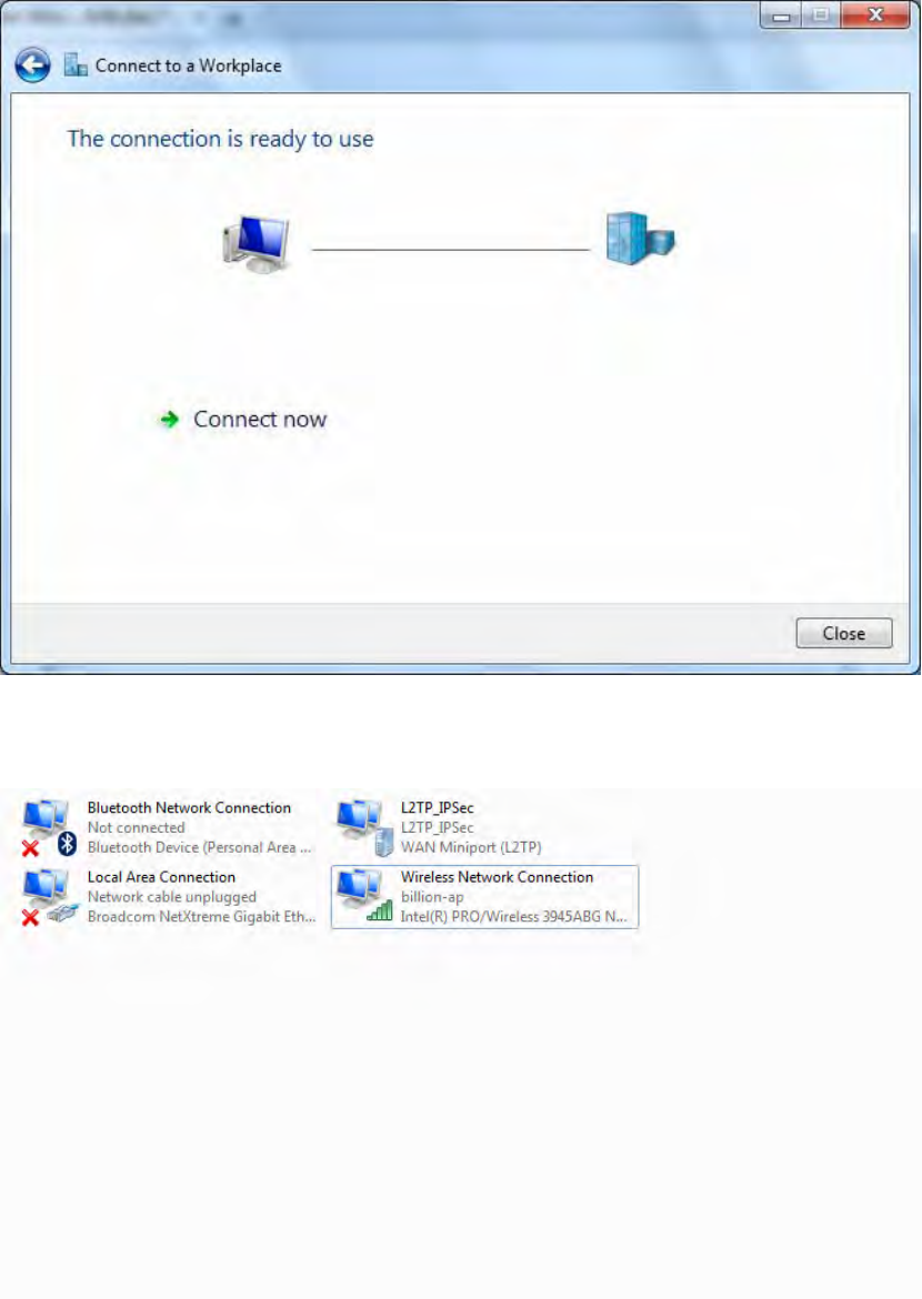
6. Connection created. Press Close.
7. Go to Network Connections shown below to check the detail of the connection. Right click
“L2TP_IPSec” icon, and select “Properties” to change the security parameters.
227
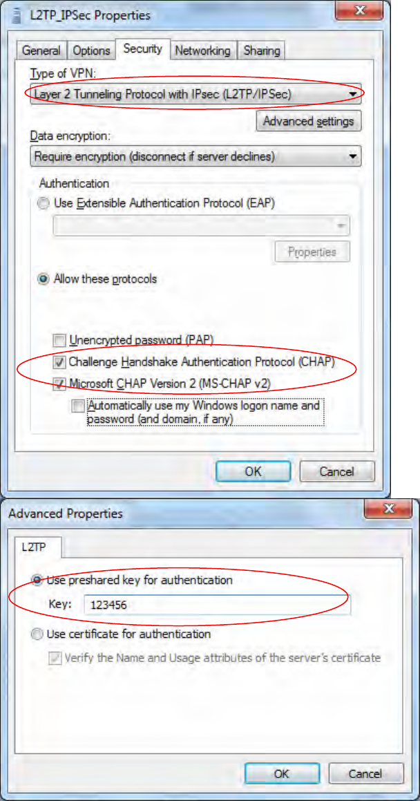
8. Chang the type of VPN to “Layer 2 Tunneling Protocol with IPSec (L2TP/IPSec)” and Click
Advanced Settings to set the pre-shared (set in IPSec) key for authentication.
228
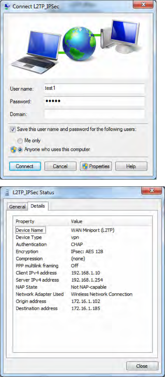
9. Go to Network connections, enter username and password to connect L2TP_IPSec and check
the connection status.
229
Example: Configuring L2TP LAN-to-LAN VPN Connection
The branch office establishes a L2TP VPN tunnel with head office to connect two private networks
over the Internet. The routers are installed in the head office and branch office accordingly.
Note: Both office LAN networks must be in different subnets with the LAN-LAN application.
Server side: Head Office
230
The above is the commonly setting for L2TP Server, set as you like for authentication and encryption.
The settings in Client side should be in accordance with settings in Server side.
Then account the L2TP Account.
231
Client Side: Branch Office
The client user can set up a tunnel connecting to the L2TP server, and can also set the tunnel as the
default route for all outgoing traffic.
Note: users can see the “Default Gateway” item in the bar, and user can check to select the tunnel
as the default gateway (default route) for traffic. If selected, all outgoing traffic will be forwarded to
this tunnel and routed to the next hop.
232
OpenVPN
OpenVPN is an open source software application that implements 2222virtual private network (VPN)
techniques for creating secure point-to-point or site-to-site connections in routed or bridged
configurations and remote access facilities. It uses a custom security protocol that utilizes 2222SSL/TLS
for key exchange. It is capable of traversing network address translation (NAT) and 2222firewalls.
OpenVPN allows 2222peers to 2222authenticate each other using a 2222pre-shared secret key, 2222certificates, or
2222username/2222password. When used in a multiclient-server configuration, it allows the server to release
an 2222authentication certificate for every client, using 2222signature and 2222Certificate authority. It uses the
2222OpenSSL encryption 2222library extensively, as well as the 2222SSLv3/TLSv1 2222protocol, and contains many
security and control features.
OpenVPN is good at portability. OpenVPN has been ported and embedded to several systems.
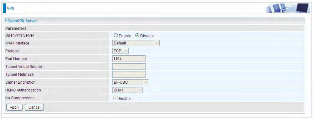
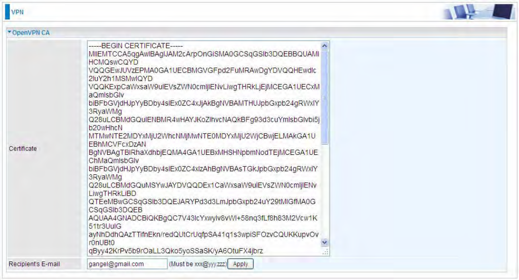
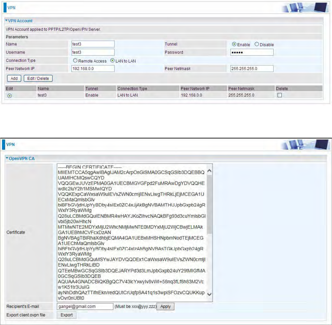
OpenVPN Server
Users can set the bassic parameters(source/destination address, protocl/port, authentication,
encyption, etc) for OpenVPN Server.
OpenVPN Server: Select Enable to activate OpenVPN Server.
WAN Interface: Select the exact WAN interface configured as source for the tunnel. Select Default
to use the now-working WAN interface for the tunnel.
Protocol: OpenVPN can run over 2222User Datagram Protocol (UDP) or 2222Transmission Control Protocol
(TCP) transports. Select the protocol.
Port Number: Port 1194 is the official assigned port number for OpenVPN
Tunnel Virtual Subnet: Set the tunnel virtual subnet IP for OpenVPN server.
Tunnel Network: Set the tunnel virtual subnet mask.
Cipher Encryption: OpenVPN uses all the ciphers available in the OpenSSL package to encrypt
both the data and channels. Select the encryption method.

233
HMAC Authentication: OpenVPN support 2222HMAC authentication, please select authentication item
from the list.
lzo Compression: Enable to use the 2222LZO compression library to compress the data stream.
Click Apply to submit your OpenVPN Server basic settings.
234
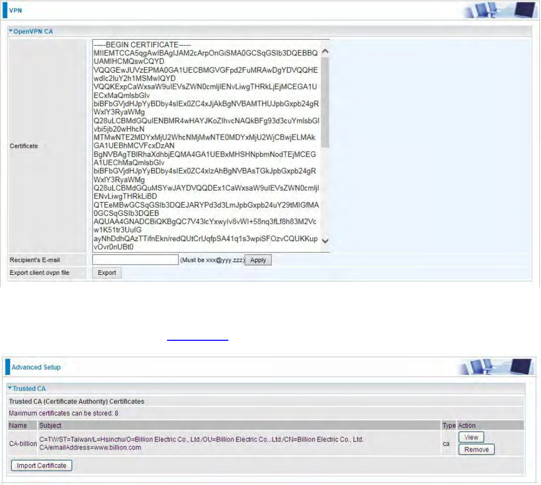
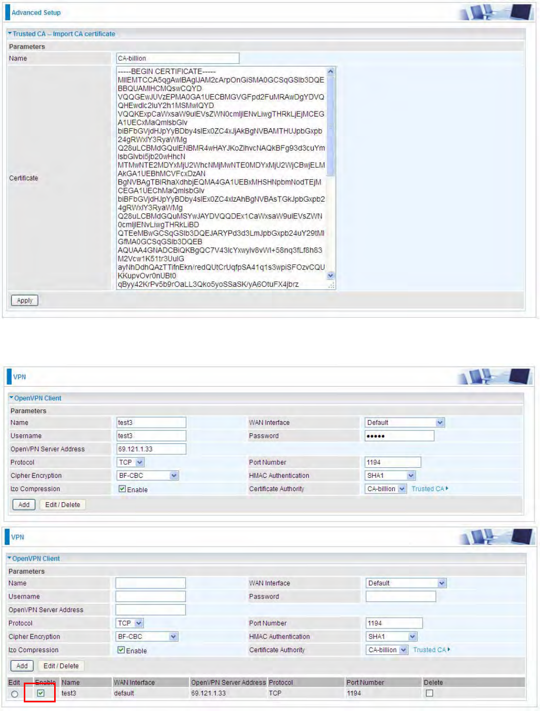
OpenVPN CA
OpenVPN offers 2222pre-shared keys, certificate-based, and username/password-based authentication,
with certificate-based being the most robust. Generally, the part offers the billion factory-defined
authentication certificate.
Recipient’s Email: Set the recipient’s email address to send the trusted CA to the OpenVPN client.
OpenVPN server and client need matched certificate to establish trusted VPN tunnel, on client side,
please import this certificate in 2222Trusted CA.
(Client side CA)
235
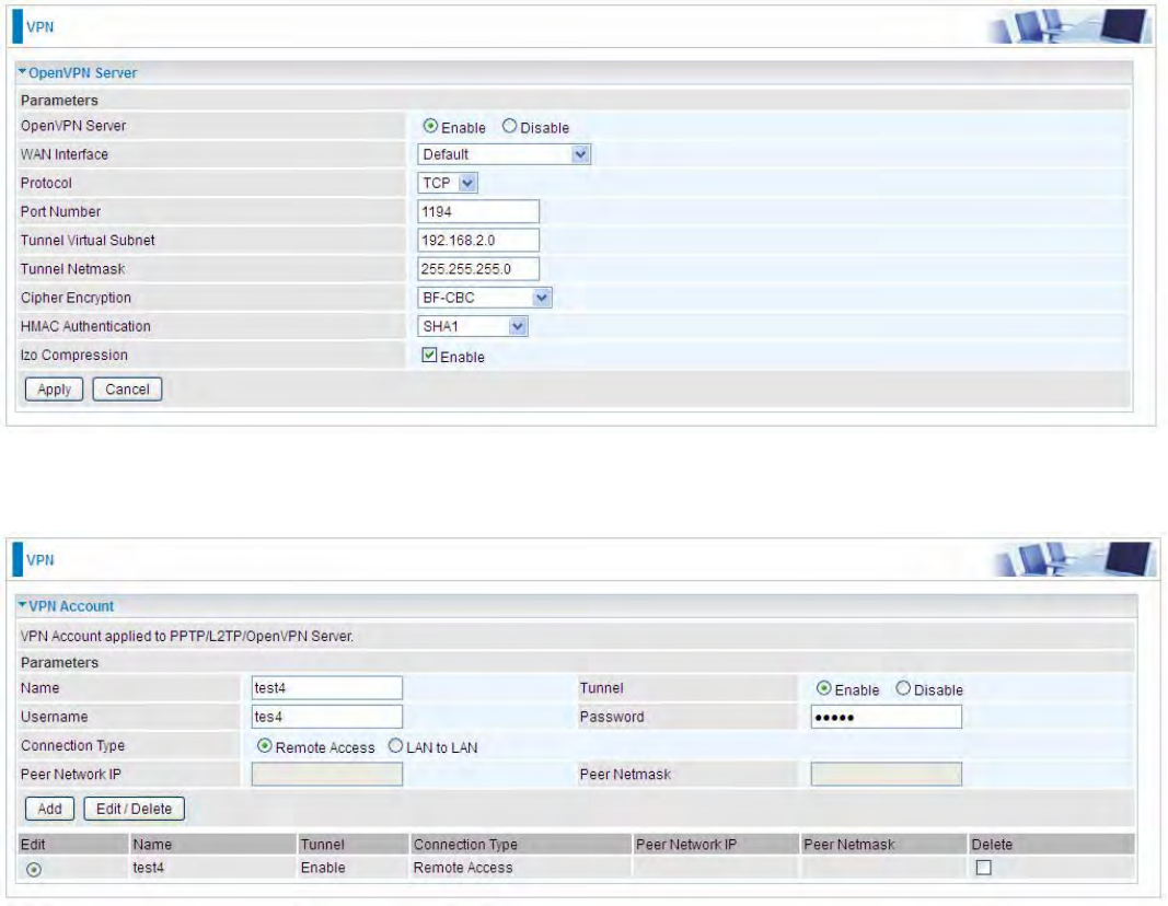
OpenVPN Client
OpenVPN client can help you dial-in the OpenVPN server to establish a trusted OpenVPN tunnel
over Internet.
Name: user-defined name for identification.
WAN Interface: Select the exact WAN interface configured as source for the tunnel. Select Default
to use the now-working WAN interface for the tunnel.
Username: Enter the username provided by your OpenVPN Server.
Password: Enter the password provided by your OpenVPN Server.
OpenVPN Server Address: Enter the WAN IP address of the OpenVPN server.
Protocol: The protocol, same as set in server side.
Port Number: 1194.
Cipher Encryption: Be consistent with what set on server side.
HMAC Authentication: Be consistent with what set on server side.
lzo Compression: Enable to use the 2222LZO compression library to compress the data stream
Certificate Authority: Select your trusted CA from your server side to establish the trusted VPN
tunnel with server.
Click Add button to save your changes.
236
How to establish OpenVPN tunnel
1. Remote Access OpenVPN
(If the client wants to remotely access the OpenVPN Server, on client side, users had better install
an OpenVPN client application/installer and connect to server accordingly. Here only give the
configuration on server side.)
Server side on router
1. Set up parameters (WAN interface, port, tunnel virtual subnet IP/mask, encryption, authentication,
etc) on OpenVPN server side.
2. Create an account for the OpenVPN tunnel for client to connect in.
237
3. Set the OpenVPN client’s E-mail address to receive trusted CA from server to establish a trusted
OpenVPN tunnel.
238
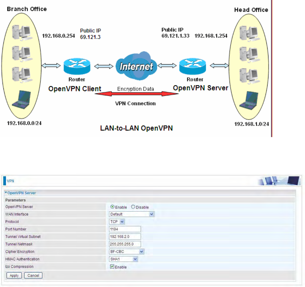
2. LAN-to-LAN OpenVPN
The branch office establishes a OpenVPN tunnel with head office to connect two private networks
over the Internet. The routers are installed in the head office and branch office accordingly.
Configured in this way, head office and branch office can access each other.
Note: Both office LAN networks must be in different subnets with the LAN-to-LAN application.
Server side: Head Office
1. Set up parameters (WAN interface, port, tunnel virtual subnet IP/mask, encryption, authentication,
etc) on OpenVPN server side.
239
2. Create an account for client to connect in
3. Set the OpenVPN client’s E-mail address to receive trusted CA from server to establish a trusted
OpenVPN tunnel.
240
Client Side: Branch Office
1. Import your trusted certificate from server side, which is used to authenticate between client and
server for establishing trusted OpenVPN tunnel.
2. On the OpenVPN client side, fill in the parameters the same as set for OpenVPN server.
241
Note: users can see the “Default Gateway” item in the bar, and user can check to select the tunnel
as the default gateway (default route) for traffic. If selected, all outgoing traffic will be forwarded to
this tunnel and routed to the next hop.
242
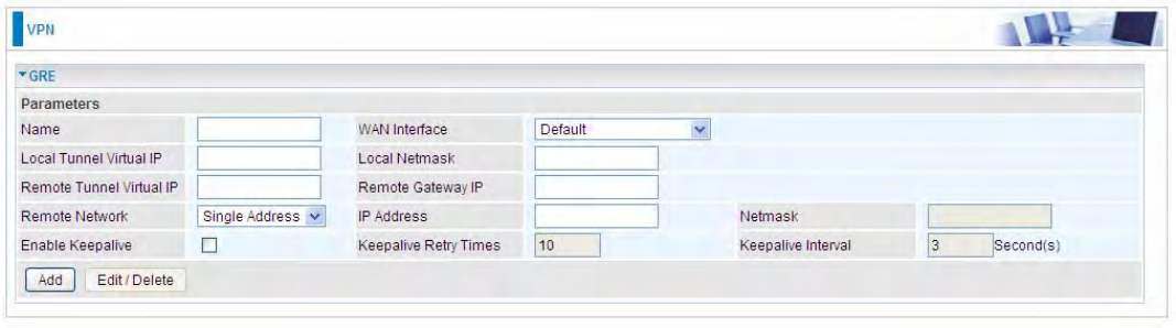
GRE
Generic Routing Encapsulation (GRE) is a tunneling protocol that can encapsulate a wide variety
of network layer protocol packets inside virtual point-to-point links over an Internet Protocol (IP)
network. And the common use can be GRE over IPSec.
Note: up to 8 tunnels can be added, but only 4 can be activated.
Name: User-defined identification.
WAN Interface: Select the exact WAN interface configured for the tunnel as the source tunnel IP.
Select Default to use the now-working WAN interface for the tunnel.
Local Tunnel Virtual IP: Please input the virtual IP for the local tunnel.
Local Netmask: Input the netmask for the local tunnel.
Remote Tunnel Virtual IP: Please input the virtual destination IP for tunnel.
Remote Gateway IP: Set the destination IP for the tunnel.
Remote Network: Select the peer topology, Single address (client) or Subnet.
IP Address: Set the IP address if the peer is a client. If the peer is a subnet, please enter the IP and
netmask.
Enable Keepalive: Normally, the tunnel interface is always up. Enable keepalive to determine when
the tunnel interface is to be closed. The local router sends keepalive packets to the peer router, if
keepalive response is not received from peer router within the allowed time (‘retry time’ multiply
‘interval’, based on default settings, the time interval can be 30 seconds), the local router will shut up
its tunnel interface.
Keepalive Retry Times: Set the keepalive retry times, default is 10.
Keepalive Interval: Set the keepalive Interval, unit in seconds. Default is 3 seconds.
243
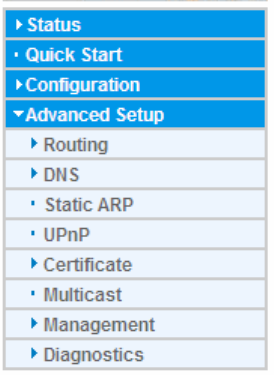
Advanced Setup
There are sub-items within the System section: Routing,DNS,Static ARP, UPnP,Certificate,
Multicast,Management, and Diagnostics.
244
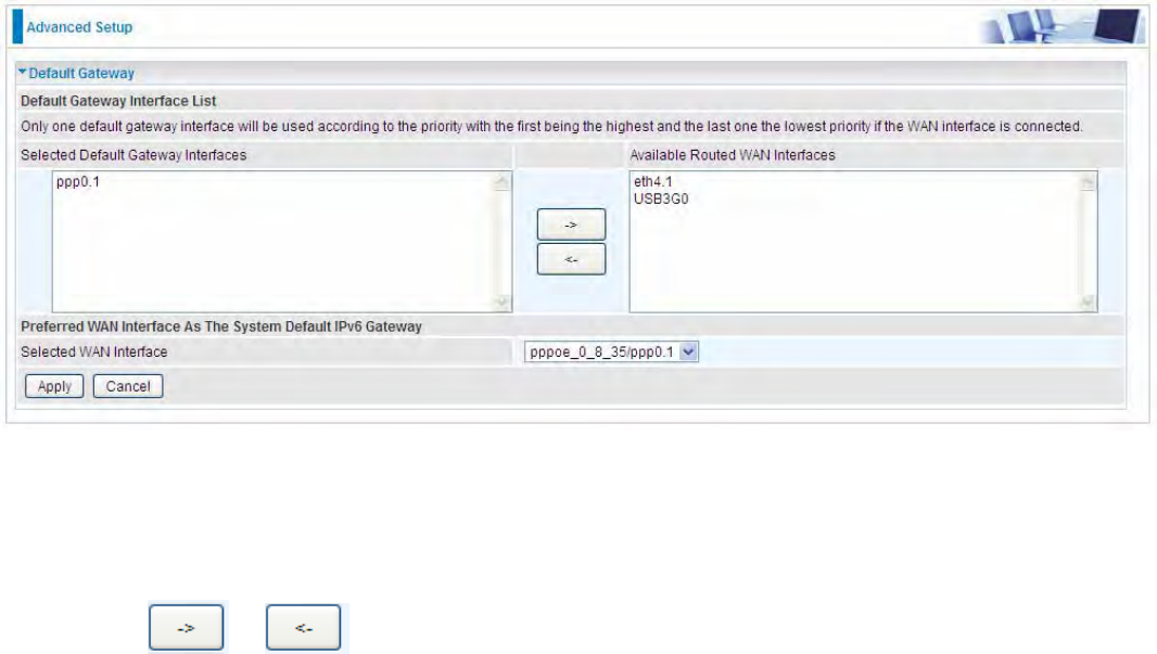
Routing
Default Gateway
WAN port: Select the port this gateway applies to.
To set Default Gateway and Available Routed WAN Interface. This interfaces are the ones you
have set in WAN section, here select the one you want to be the default gateway by moving the
interface via or . And select a Default IPv6 Gateway from the drop-down menu.
Note: Only one default gateway interface will be used according to the priority with the first being the
highest and the last one the lowest priority if the WAN interface is connected.
245
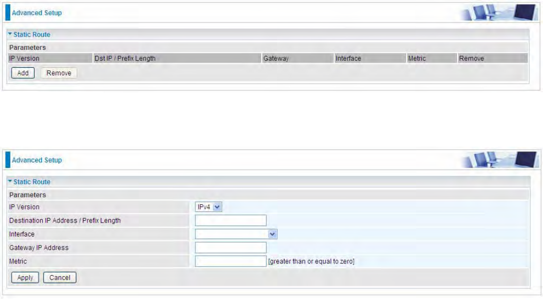
Static Route
With static route feature, you can control the routing of all the traffic across your network. With each
routing rule created, you can specifically assign the destination where the traffic will be routed.
Above is the static route listing table, click Add to create static routing.
IP Version: Select the IP version, IPv4 or IPv6.
Destination IP Address / Prefix Length: Enter the destination IP address and the prefix length. For
IPv4, the prefix length means the number of ‘1’ in the submask, it is another mode of presenting
submask. One IPv4 address,192.168.1.0/24, submask is 255.255.255.0. While in IPv6, IPv6
address composes of two parts, thus, the prefix and the interface ID, the prefix is like the net ID in
IPv4, and the interface ID is like the host ID in IPv4. The prefix length is to identify the net ID in the
address. One IPv6 address, 3FFE:FFFF:0:CD30:0:0:0:0 / 64, the prefix is 3FFE:FFFF:0:CD3.
Interface: The exit interface of local router to the next hop.
Gateway IP Address: Enter the gateway IP address/ the entry address of the next hop, .
Metric: Metric is the hops from local to destination, which signals the quality of the link, to
determine the optimal route. Enter one number greater than or equal to 0.
Click Apply to apply this route and it will be listed in the route listing table.
246
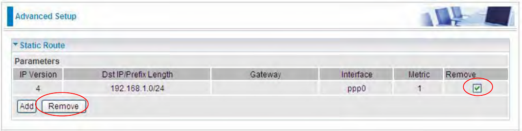
In listing table you can remove the one you don’t want by checking the checking box and press
Remove button.
247
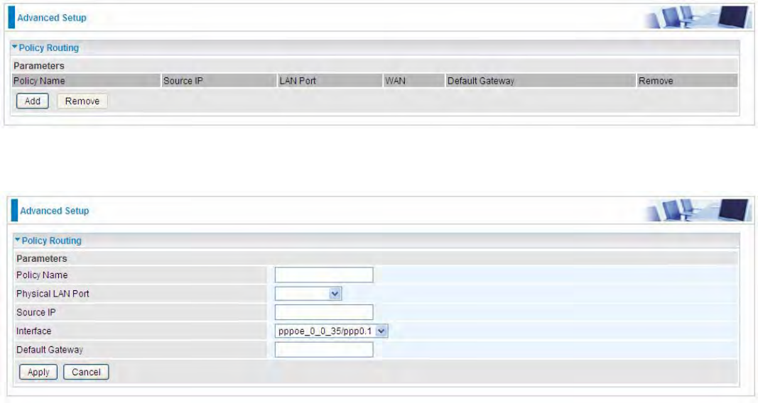
Policy Routing
Here users can set a route for the host (source IP) in a LAN to access outside through a specified a
WAN interface to the next hop.
The following is the policy Routing listing table.
Click Add to create a policy route.
Policy Name: User-defined name.
Physical LAN Port: Select the LAN port.
Source IP: Enter the Host Source IP.
Interface: Select the WAN interface (exit interface) of local router to the next hop.
Default Gateway: Enter the gateway IP address/ the entry address of the next hop,
Click Apply to apply your settings. And the item will be listed in the policy Routing listing table. Here
if you want to remove the route, check the remove checkbox and press Remove to delete it.
248
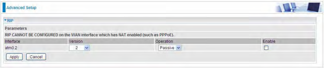
RIP
RIP, Router Information Protocol, is a simple Interior Gateway Protocol (IGP). RIP has two versions,
RIP-1 and RIP-2.
Interface: The interface the rule applies to.
Version: Select the RIP version, RIP-1, RIP-2 and both.
Operation: RIP has two operation mode.
LPassive: only receive the routing information broadcasted by other routers and modifies its
routing table according to the received information.
LActive: working in this mode, the router sends and receives RIP routing information and
modifies routing table according to the received information.
Enable: check the checkbox to enable RIP rule for the interface.
Note: RIP can’t be configured on the WAN interface which has NAT enabled (such as PPPoE).
Click Apply to apply your settings.
249
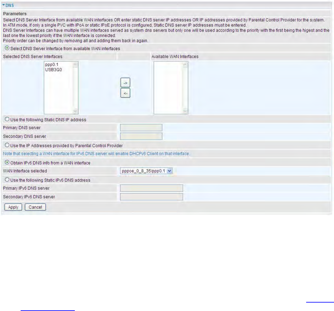
DNS
DNS, Domain Name System, is a distributed database of TCP/IP application. DNS provides
translation of Domain name to IP.
DNS
¾IPv4
Three ways to set an IPv4 DNS server
LSelect DNS server from available WAN interfaces: Select a desirable WAN interface as the
IPv4 DNS server.
LUser the following Static DNS IP address: To specify DNS server manually by entering your
primary and secondary DNS server addresses.
LUse the IP address provided by Parental Control Provider: If user registers and gets an
DNS account in the parental control provider website, expecting to enjoy a more reliable and
safer internet surfing environment, please select this option (need to configure at Parental
Control Provider).
¾IPv6:
IPv6 DNS Server’s operation is similar to IPv4 DNS server. There are two modes to get DNS server
address: Auto and Static mode.
Obtain IPv6 DNS info from a WAN interface
WAN Interface selected: Select one configured IPv6 WAN connection from the drop-down menu to
be as an IPv6 DNS.
Use the following Static IPv6 DNS address
250
Primary IPv6 DNS Server / Secondary IPv6 DNS Server: Type the specific primary and secondary
IPv6 DNS Server address.
251
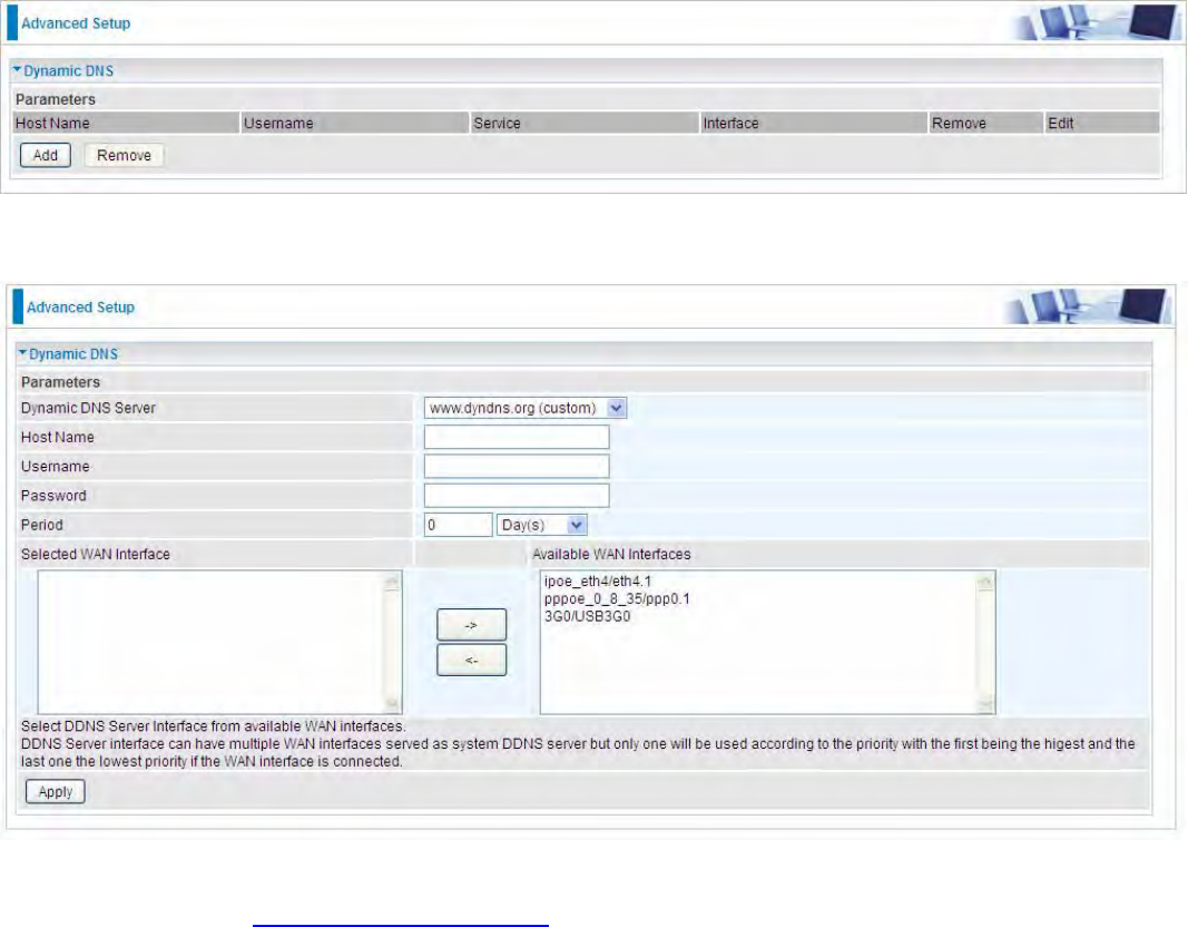
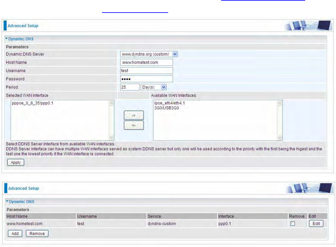
Dynamic DNS
The Dynamic DNS function allows you to alias a dynamic IP address to a static hostname, allowing
users whose ISP does not assign them a static IP address to use a domain name. This is especially
useful for hosting servers via your ADSL connection, so that anyone wishing to connect to you may
use your domain name, rather than having to use your dynamic IP address, which changes from
time to time. This dynamic IP address is the WAN IP address of the router, which is assigned to you
by your ISP.
Here users can register different WAN interfaces with different DNS(es).
Click Add to register a WAN interface with the exact DNS.
You will first need to register and establish an account with the Dynamic DNS provider using their
website, for example http://www.dyndns.org/
Dynamic DNS Server: Select the DDNS service you have established an account with.
Host Name, Username and Password: Enter your registered domain name and your username
and password for this service.
Period: Set the time period between updates, for the Router to exchange information with the DDNS
server. In addition to updating periodically as per your settings, the router will perform an update
when your dynamic IP address changes.
Selected WAN Interface: Select the Interface that is bound to the registered Domain name.
252
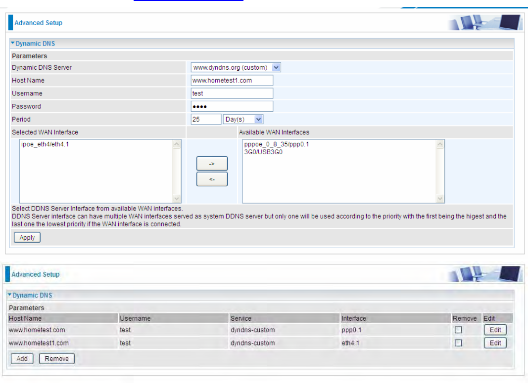
User can register different DDNS to different interfaces.
Examples: Note first users have to go to the Dynamic DNS registration service provider to register
an account.
User test register two Dynamic Domain Names in DDNS provider http://www.dyndns.org/ .
1. pppoe_0_8_35 with DDNS: www.hometest.com using username/password test/test
253
2. ipoe_eth4 with DDNS: www.hometest1.com using username/password test/test.
254
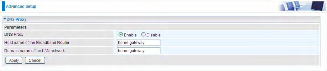
DNS Proxy
DNS proxy is used to forward request and response message between DNS Client and DNS Server.
Hosts in LAN can use router serving as a DNS proxy to connect to the DNS Server in public to
correctly resolve Domain name to access the internet.
DNS Proxy: Select whether to enable or disable DNS Proxy function, default is enabled.
Host name of the Broadband Router: Enter the host name of the router. Default is home.gateway.
Domain name of the LAN network: Enter the domain name of the LAN network. home.gateway.
255
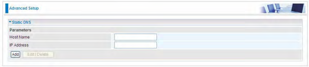
Static DNS
Static DNS is a concept relative to Dynamic DNS; in static DNS system, the IP mapped is static
without change.
You can map the specific IP to a user-friendly domain name. In LAN, you can map a PC to a domain
name for convenient access. Or you can set some well-known Internet IP mapping item so your
router will response quickly for your DNS query instead of querying from the ISP’s DNS server.
Host Name: Type the domain name (host name) for the specific IP .
IP Address: Type the IP address bound to the set host name above.
Click Add to save your settings.
256
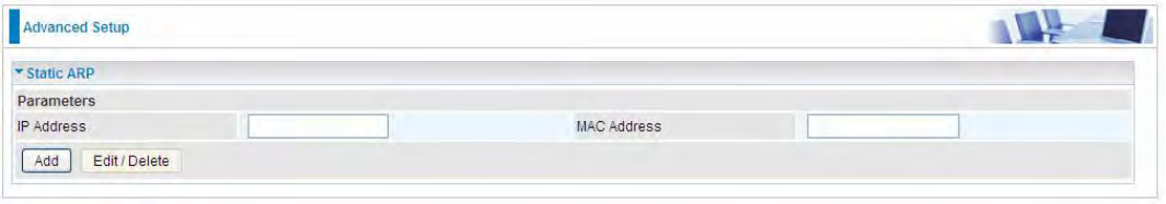
Static ARP
ARP (Address Resolution Protocol) is a TCP/IP protocol that allows the resolution of network layer
addresses into the link layer addresses. And “Static ARP” here allows user to map manually the
layer-3 MAC (Media Access Control) address to the layer-2 IP address of the device.
IP Address: Enter the IP of the device that the corresponding MAC address will be mapped to.
MAC Address: Enter the MAC address that corresponds to the IP address of the device.
Click Add to confirm the settings.
257
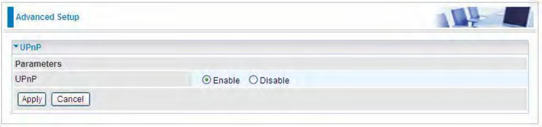
UPnP
UPnP offers peer-to-peer network connectivity for PCs and other network devices, along with control
and data transfer between devices. UPnP offers many advantages for users running NAT routers
through UPnP NAT Traversal, and on supported systems makes tasks such as port forwarding
much easier by letting the application control the required settings, removing the need for the user to
control advanced configuration of their device.
Both the user’s Operating System and the relevant application must support UPnP in addition to the
router. Windows XP and Windows Me natively support UPnP (when the component is installed), and
Windows 98 users may install the Internet Connection Sharing client from Windows XP in order to
support UPnP. Windows 2000 does not support UPnP.
UPnP:
LEnable: Check to enable the router’s UPnP functionality.
LDisable: Check to disable the router’s UPnP functionality.
258
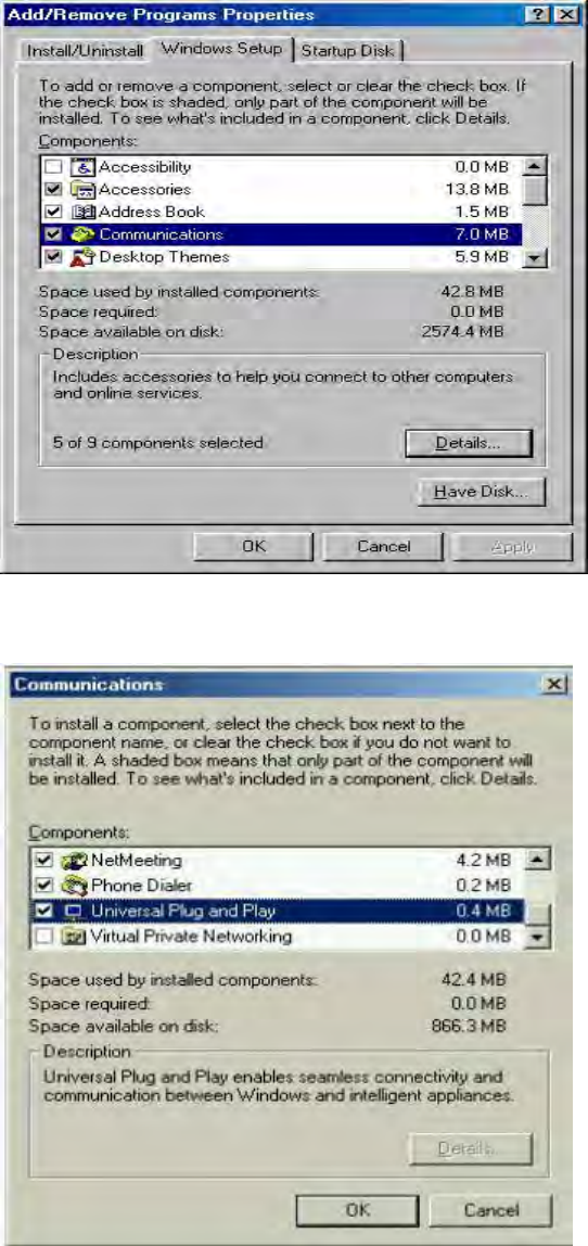
Installing UPnP in Windows Example
Follow the steps below to install the UPnP in Windows Me.
Step 1: Click Start and Control Panel. Double-click Add/Remove Programs.
Step 2: Click on the Windows Setup tab and select Communication in the Components selection
box. Click Details.
Step 3: In the Communications window, select the Universal Plug and Play check box in the
Components selection box.
Step 4: Click OK to go back to the Add/Remove Programs Properties window. Click Next.
259
Step 5: Restart the computer when prompted.
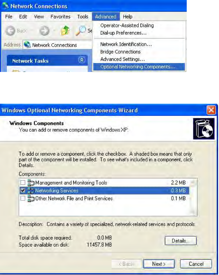
Follow the steps below to install the UPnP in Windows XP.
Step 1: Click Start and Control Panel.
Step 2: Double-click Network Connections.
Step 3: In the Network Connections window, click Advanced in the main menu and select Optional
Networking Components ….
The Windows Optional Networking Components Wizard window displays.
Step 4: Select Networking Service in the Components selection box and click Details.
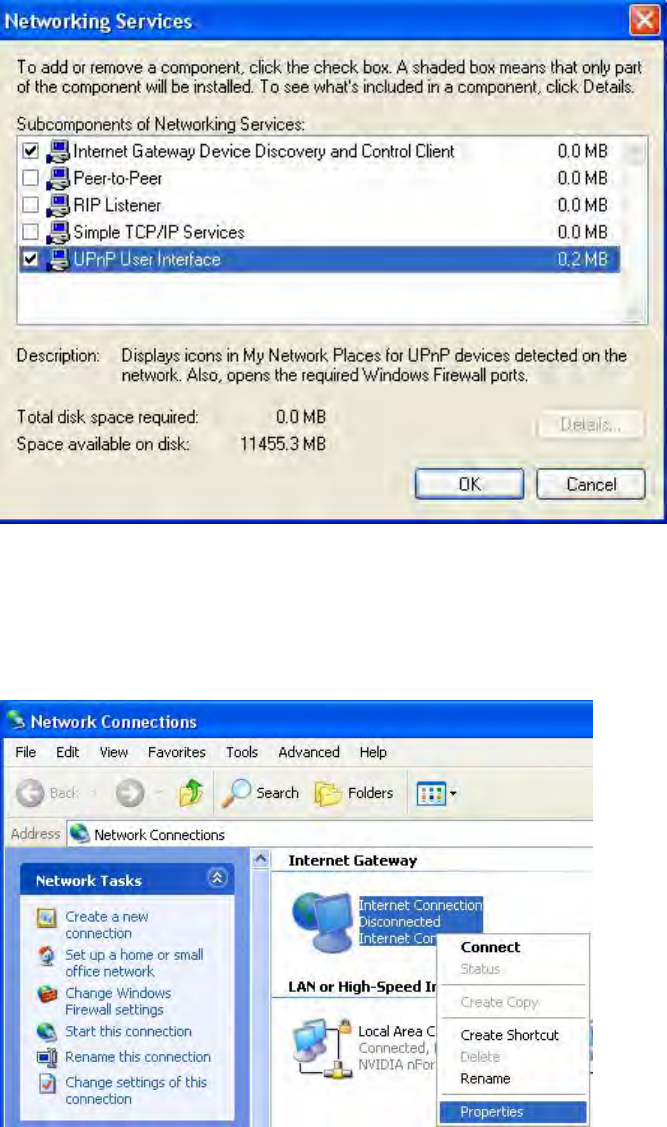
260
Step 5: In the Networking Services window, select the Universal Plug and Play check box.
Step 6: Click OK to go back to the Windows Optional Networking Component Wizard window and
click Next.
Auto-discover Your UPnP-enabled Network Device
Step 1: Click start and Control Panel. Double-click Network Connections. An icon displays under
Internet Gateway.
Step 2: Right-click the icon and select Properties.
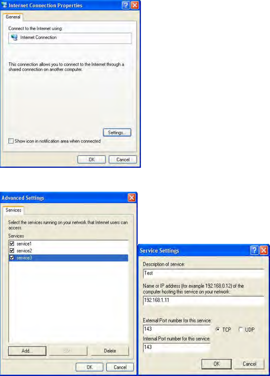
261
Step 3: In the Internet Connection Properties window, click Settings to see the port mappings that
were automatically created.
Step 4: You may edit or delete the port mappings or click Add to manually add port mappings.
Step 5: Select Show icon in notification area when connected option and click OK. An icon displays
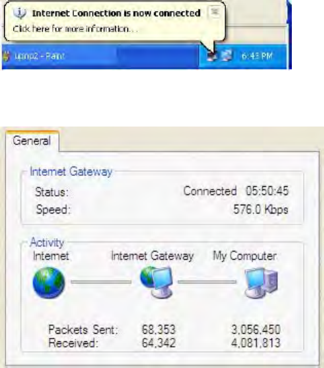
262
in the system tray
Step 6: Double-click on the icon to display your current Internet connection status.
263
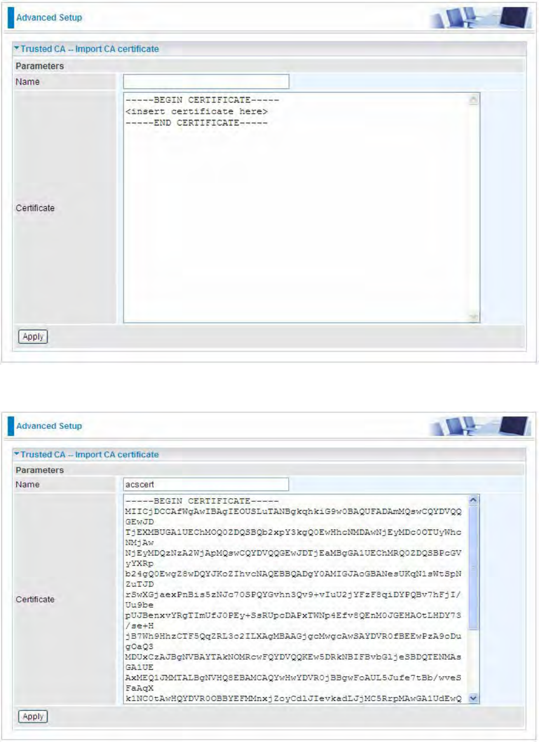
Certificate
This feature is used for TR069 ACS Server authentication of the device using certificate, if
necessary. If the imported certificate does not match the authorized certificate of the ACS Server,
the device will have no access to the server.
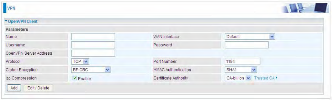
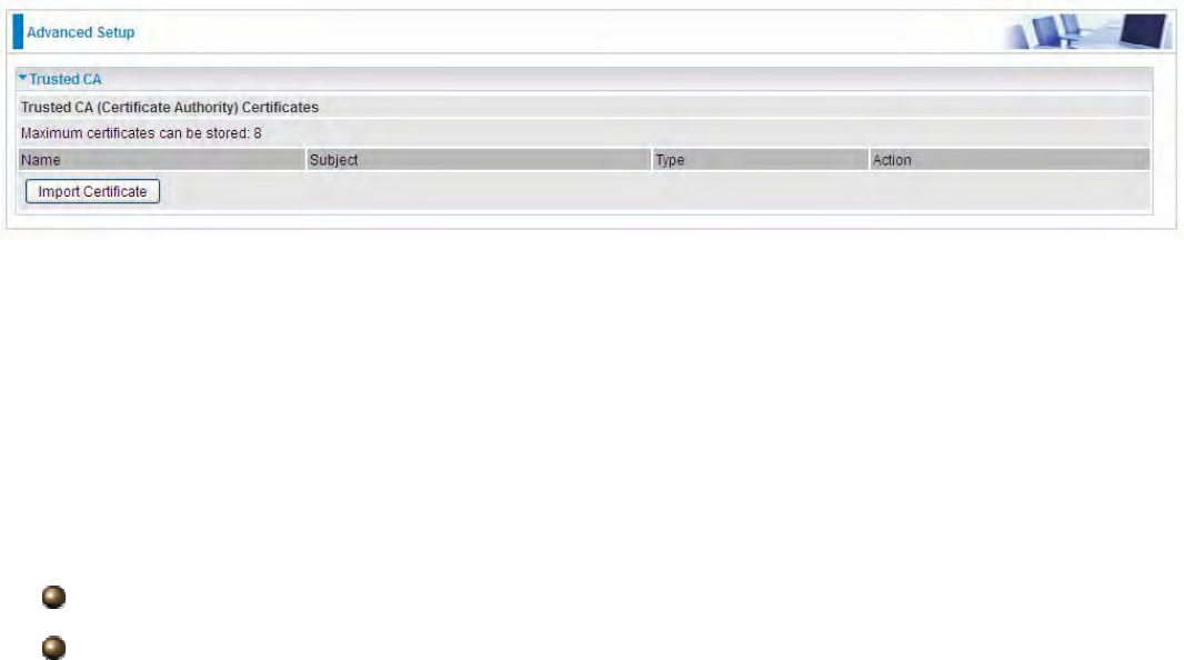
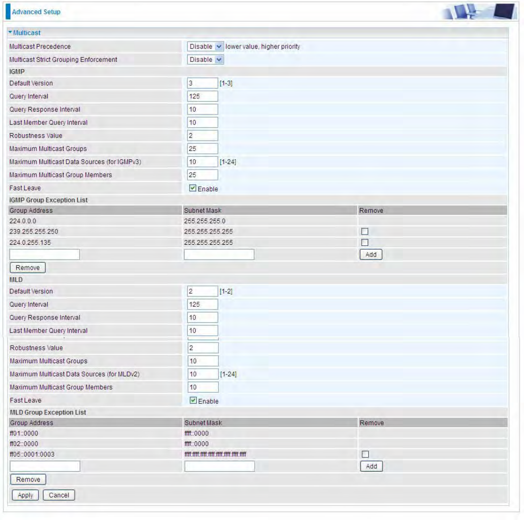
Trusted CA
Certificate Name: The certificate identification name.
Subject: The certificate subject.
Type: The certificate type information. "ca", indicates that the certificate is a CA-signed certificate.
"self", indicates that the certificate is a certificate owner signed one.
"x.509", indicates the certificate is the one created and signed according to the definition of Public-
Key System suggested by x.509.
Action:
View: view the certificate.
Remove: remove the certificate.
264
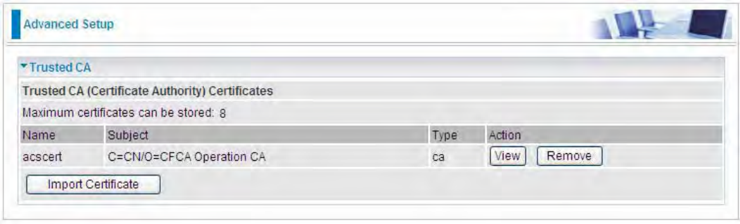
Click Import Certificate button to import your certificate.
Enter the certificate name and insert the certificate.
265
Click Apply to confirm your settings.
266
Multicast
Multicast is one of the three network transmission modes, Unicast, Multicast, Broadcast. It is a
transmission mode that supports point-to-multipoint connections between the sender and the
recipient. IGMP protocol is used to establish and maintain the relationship between IP host and the
host directly connected multicast router.
IGMP stands for Internet Group Management Protocol, it is a communications protocols used to
manage the membership of Internet Protocol multicast groups. IGMP is used by IP hosts and the
adjacent multicast routers to establish multicast group members. There are three versions for IGMP,
that is IGMPv1, IGMPv2 and IGMPv3.
MLD, short for Multicast Listener Discovery protocol, is a component if the Internet Protocol
version 6(IPv6) suite. MLD is used by IPv6 to discover multicast listeners on a directly attached link,
much as IGMP used in IPv4. The protocol is embedded in ICMPv6 instead of using a separate
protocol. MLDv1 is similar to IGMPv2 and MLDv2 is similar to IGMPv3.
267
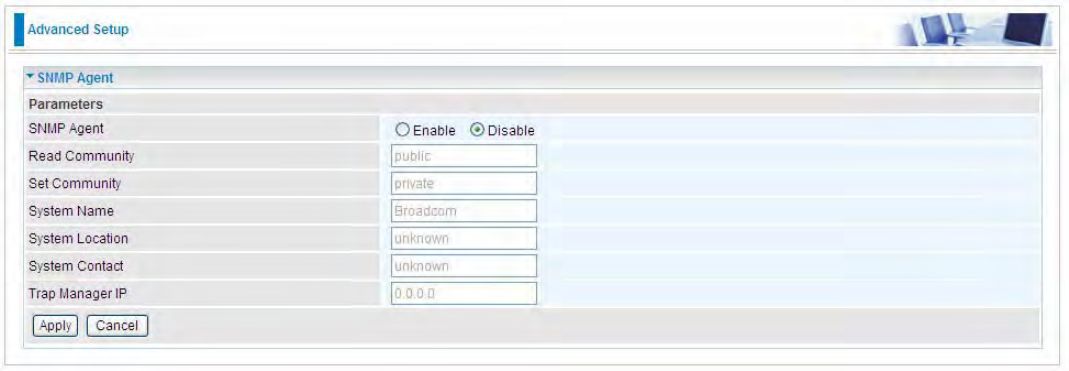
IGMP
Multicast Precedence: It is for multicast QoS. With lower multicast precedence, IGMP packets will
be put into higher-priority queue. Default is set to disable.
Default Version: Enter the supported IGMP version, 1-3, default is IGMP v3.
Query Interval: Enter the periodic query interval time (sec) the multicast router sending the query
message to hosts to understand the group membership information.
Query Response Interval: Enter the response interval time (sec).
Last Member Query Interval: Enter the interval time (sec) the multicast router query the specified
group after it has received leave message.
Robustness Value: Enter the router robustness parameter, 2-7, the greater the robustness value,
the more robust the Querier is.
Maximum Multicast Groups: Enter the Maximum Multicast Groups.
Maximum Multicast Data Sources( for IGMP v3): Enter the Maximum Multicast Data Sources,1-
24.
268
Maximum Multicast Group Members: Enter the Maximum Multicast Group Members.
Fast leave: Check to determine whether to support fast leave. If this value is enabled, IGMP proxy
removes the membership of a group member immediately without sending an IGMP membership
query on downstream. This is very helpful if user wants fast channel (group change) changing in
cases like IPTV environment.
IGMP Exception List
The multicast group(s) listed in the IGMP exception list will not be subject to IGMP snooping.
Here the pair of group address and the subnet mask indicates a multicast group range, and
224.0.1.0/255.255.255.0 is a multicast group range of 224.0.1.0 - 224.0.1.255.
Group Address: Set the exception multicast group address.
Subnet Mask: Set the multicast subnet mask
Remove: Select the group which is to be removed.
MLD
Default Version: Enter the supported MLD version, 1-2, default is MLDv2.
Query Interval: Enter the periodic query interval time (sec) the multicast router sending the query
message to hosts to understand the group membership information.
Query Response Interval: Enter the response interval time (sec).
Last Member Query Interval: Enter the interval time (sec) the multicast router query the specified
group after it has received leave message.
Robustness Value: Enter the router robustness parameter, default is 2, the greater the robustness
value, the more robust the Querier is.
Maximum Multicast Groups: Enter the Maximum Multicast Groups.
Maximum Multicast Data Sources( for MLDv2): Enter the Maximum Multicast Data Sources,1-24.
Maximum Multicast Group Members: Enter the Maximum Multicast Group Members.
Fast leave: Check to determine whether to support fast leave. If this value is enabled, MLD proxy
removes the membership of a group member immediately without sending an MLD membership
query on downstream. This is very helpful if user wants fast channel (group change) changing in
cases like IPTV environment.
MLD Exception List
The multicast group(s) listed in the MLD exception list will not be subject to MLD snooping.
Group Address: Set the exception multicast group address.
Subnet Mask: Set the multicast subnet mask
Remove: Select the group which is to be removed.
.
269
Management
SNMP Agent
SNMP, Simple Network Management Protocol, is the most popular one in network. It consists of
SNMP ManagerˈSNMP Agent and MIB. Every network device supporting SNMP will have a SNMP
Agent which is a management software running in the device.
SNMP Manager, the management software running on the server, it uses SNMP protocol to send
GetRequestǃGetNextRequest, SetRequest message to Agent to view and change the information
of the device.
SNMP Agents, the management software running in the device, accepts the message from the
manager, Reads or Writes the management variable in MIB accordingly and then generates
Response message to send it to the manager. Also, agent will send Trap message to the manager
when agent finds some exceptions.
Trap message, is the message automatically sent by the managed device without request to the
manager about the emergency events.
SNMP Agent: enable or disable SNMP Agent.
Read Community: Type the Get Community, which is the authentication for the incoming Get-and
GetNext requests from the management station.
Set Community: Type the Set Community, which is the authentication for incoming Set requests
from the management station.
System Name: here it refers to your router.
System Location: user-defined location.
System Contact: user-defined contact message.
Trap manager IP: enter the IP address of the server receiving the trap sent by SNMP agent.
270
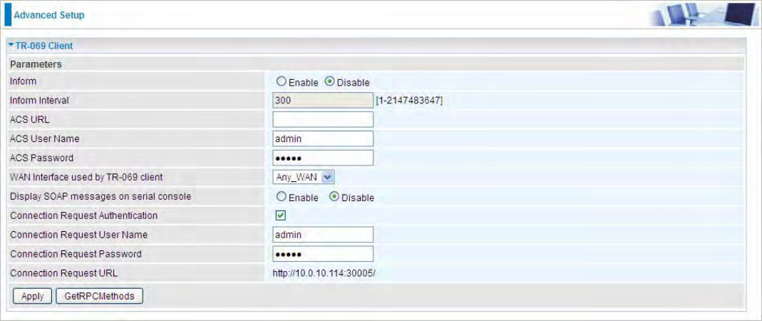
TR- 069 Client
TR-069 (short for Technical Report 069) is a DSL Forum (which was later renamed as Broadband
Forum) technical specification entitled CPE WAN Management Protocol (CWMP). It defines an
application layer protocol for remote management of end-user devices.
As a bidirectional SOAP/HTTP based protocol it can provides the communication between customer
premises equipment (CPE) and Auto Configuration Server (ACS). It includes both a safe
configuration and the control of other CPE management functions within an integrated framework. In
the course of the booming broadband market, the number of different internet access possibilities
grew as well (e.g. modems, routers, gateways, set-top box, VoIP-phones).At the same time the
configuration of this equipment became more complicated –too complicated for end-users. For this
reason, TR-069 was developed. It provides the possibility of auto configuration of the access types.
Using TR-069 the terminals can get in contact with the Auto Configuration Servers (ACS) and
establish the configuration automatically and let ACS configure CPE automatically.
Inform: select enable to let CPE be authorized to send Inform message to automatically connect to
ACS.
Inform Interval: Specify the inform interval time (sec) which CPE used to periodically send inform
message to automatically connect to ACS. When the inform interval time arrives, the CPE will send
inform message to automatically connect to ACS.
ACS URL: Enter the ACS server login name.
ACS User Name: Specify the ACS User Name for ACS authentication to the connection from CPE.
ACS password: Enter the ACS server login password.
WAN interface used by TR-069: select the interface used by TR-069.
Display SOAP message on serial console: select whether to display SOAP message on serial
console.
Connection Request Authentication: Check to enable connection request authentication feature.
Connection Request User Name: Enter the username for ACS server to make connection request.
Connection Request User Password: Enter the password for ACS server to make connection
request.
Connection Request URL: Automatically match the URL for ACS server to make connection
request.
271
GetRPCMethods
˖
Supported by both CPE and ACS, display the supported RFC listing methods.
Click Apply to apply your settings.
272
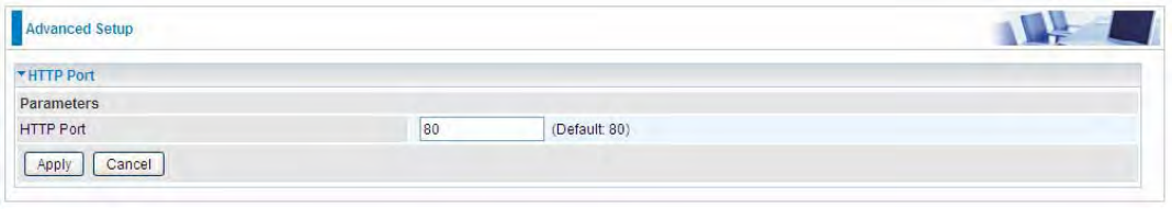
HTTP Port
The device equips user to change the embedded web server accessing port. Default is 80.
273
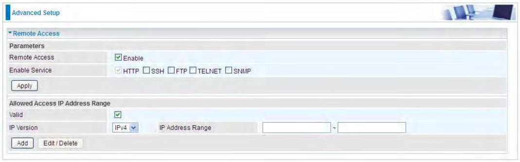
Remote Access
It is to allow remote access to the router to view or configure.
Remote Access: Select “Enable” to allow management access from remote side (mostly from
internet). If disabled, no remote access is allowed for any IPs even if you set allowed access IP
address. So, please note that enabling remote access is an essential step before granting remote
access to IPs.
Enable Service: Select to determine which service(s) is (are) allowed for remote access when
remote access is enabled. By default (on condition that remote access is enabled), the web service
(HTTP) is allowed for remote access.
Click Apply button to submit your settings.
"Allowed Access IP Address Range" was used to restrict which IP address could login to access
system web GUI.
Valid: Enable/Disable Allowed Access IP Address Range
IP Address Range: Specify the IP address Range, IPv4 and IPv6 address range can be supported,
users can set IPv4 and IPv6 address range individually.
Click Add to add an IP Range to allow remote access.
Note: 1. If user wants to grant remote access to IPs, first enable Remote Access.
2. Remote Access enabled:
1) Enable Valid for the specific IP(s) in the IP range to allow the specific IP(s) to remote access the
router.
2) Disable Valid for all specific IP(s) in the IP range to allow any IP(s) to remote access the router.
3) No listing of IP range is to allow any IP(s) to remote access the router.
274
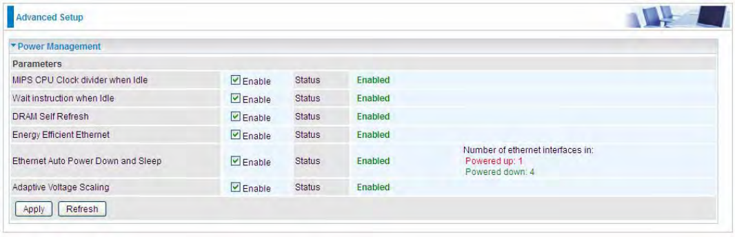
Power Management
Power management is a feature of some electrical appliances, especially computers that turn off the
power or switch to a low-power state when inactive.
Five main parameters are listed for users to check to manage the performance of the router.
275
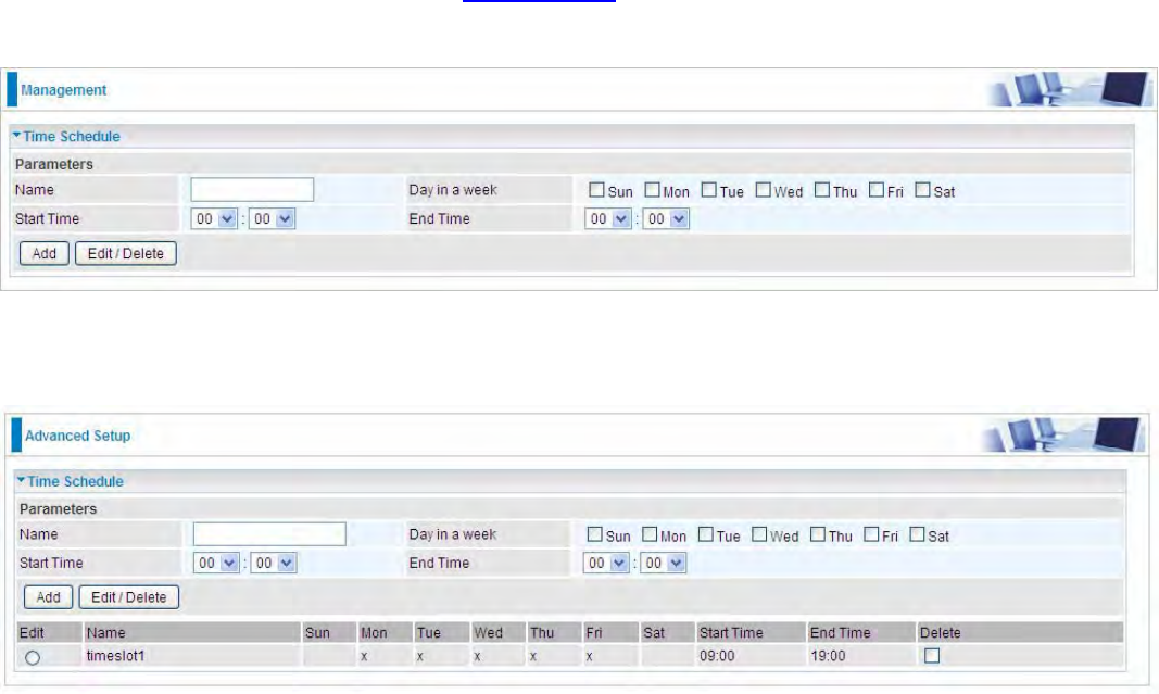
Time Schedule
The Time Schedule supports up to 32 timeslots which helps you to manage your Internet connection.
In each time profile, you may schedule specific day(s) i.e. Monday through Sunday to restrict or
allowing the usage of the Internet by users or applications.
This Time Schedule correlates closely with router’s time, since router does not have a real time
clock on board; it uses the Simple Network Time Protocol (SNTP) to get the current time from an
SNTP server from the Internet. Refer to Internet Time for details. You router time should synchronize
with NTP server.
For example, user can add a timeslot named “timeslot1” features a period of 9:00-19:00 on every
weekday.
276
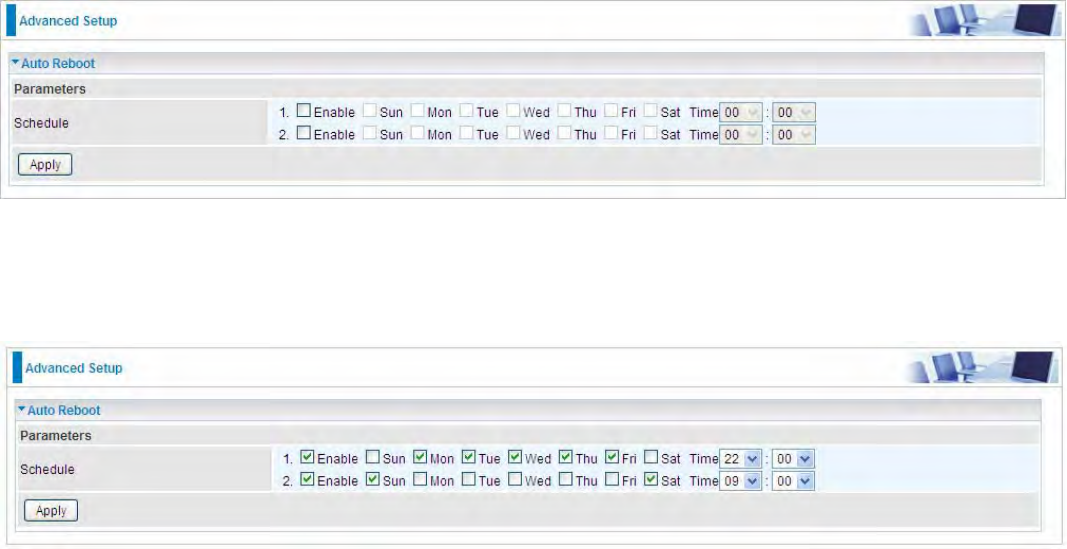
Auto Reboot
Auto reboot offers flexible rebooting service (reboot with the current configuration) of router for users
in line with scheduled timetable settings.
Enable to set the time schedule for rebooting.
For example, the router is scheduled to reboot at 22:00 every single weekday, and to reboot at 9:00
on Saturday and Sunday. You can set as follows:
277
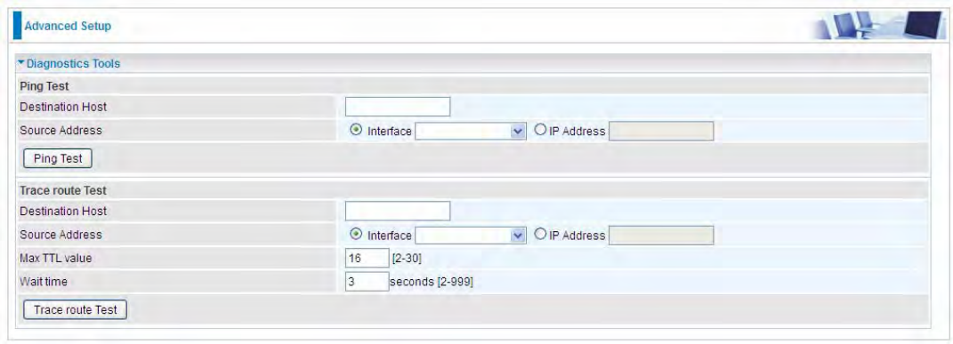
Diagnostics
Diagnostics Tools
BiPAC 8700AX-1600 offers diagnostics tools including “Ping” and “Trace route test” tools to check for
problems associated with network connections.
Ping Test: to verify the connectivity between source and destination.
Destination Host: Enter the destination host (IP, domain name) to be checked for connectivity.
Source Address: Select or set the source address to test the connectivity from the source to the
destination.
Ping Test: Press this button to proceed ping test.
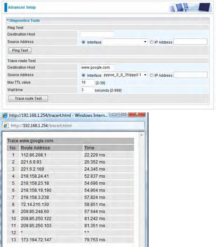
Trace route Test: to trace the route to see how many hops (also see the exact hops) the packet of
data has to take to get to the destination.
Destination Host: Set the destination host (IP, domain name) to be traced.
Source Address: Select or set the source address to trace the route from the source to the
destination.
Max TTL value: Set the max Time to live (TTL) value.
Wait time: Set waiting time for each response in seconds.
278
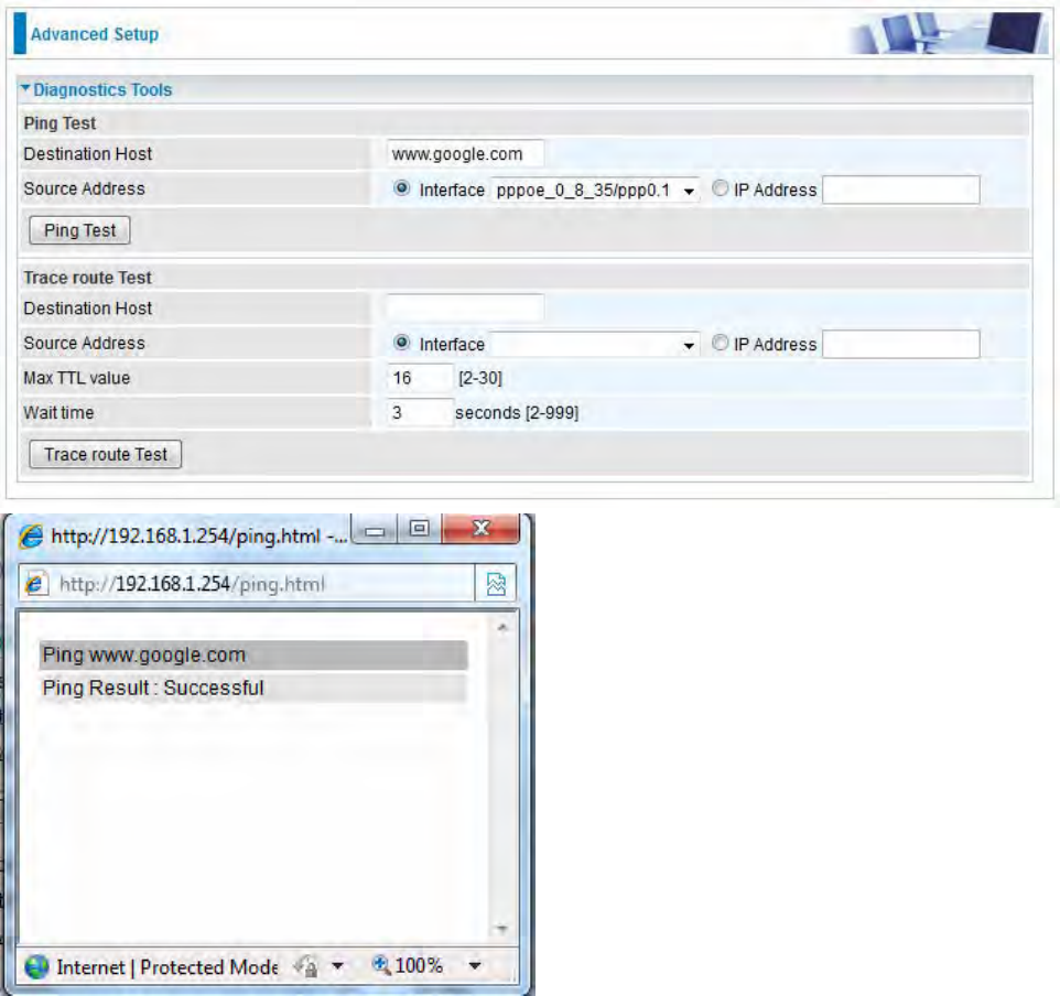
Example: Ping www.google.com
279
Example: “trace” www.google.com
280
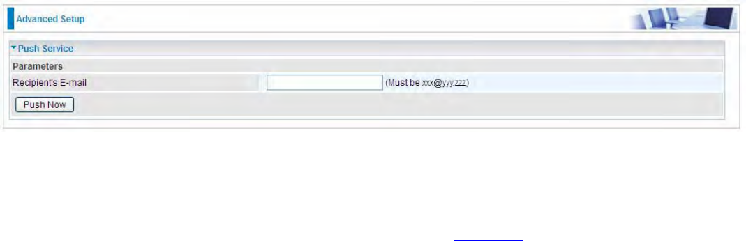
Push Service
With push service, the system can send email messages with consumption data and system
information.
Recipient’s E-mail: Enter the destination mail address. The email is used to receive system log ˈ
system configurationˈsecurity log sent by the device when the Push Now button is pressed
(information sent only when pressing the button ), but the mail address is not remembered.
Note: Please first set correct the SMTP server parameters in Mail Alert.
281
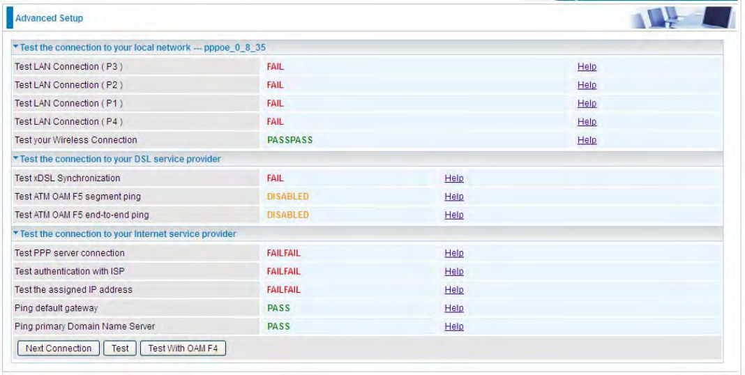
Diagnostics
Check the connections, including Ethernet connection, Internet Connection and wireless connection.
Click Help link that can lead you to the interpretation of the results and the possible, simply
troubleshooting.
282
Ethernet OAM
8700AX-1600 offers industry standard OAM capabilities to enable network providers to provision
and operate their networks with full visibility and control, simply and efficiently to minimize ongoing
OPEX.
Both peers should be Ethernet-OAM-enabled.
There are two phases of how Ethernet OAM is usually realized:
1.) Ethernet Link OAM: Ethernet in the First Mile (EFM) Link OAM as defined in IEEE 802.3ah,
Designed for testing and maintaining access links between EFM-OAM-enabled devices on L2. It
includes a set of discovery, link monitoring, remote failure detection and remote loop-back protocols.
2). Ethernet Service OAM (802.1ag/Y1.1731): designed to detect and isolate connectivity faults
within the customer service path and ensure a health service end to end.
802/1ag/CFM enable Ethernet services to be partitioned into maintenance domains with
maintenance endpoints (MEP) and intermediate points (MIP) across which continuity check, link
trace and loopback tests can be performed as needed to validate connection integrity.
Y1.1731 extends beyond CFM (802.1ag) to support performance monitoring and testing of key
Ethernet service attributes including frame loss, frame delay, and frame delay variation, which are
necessary for ensuring conformance to SLAs and verifying end to end service quality.
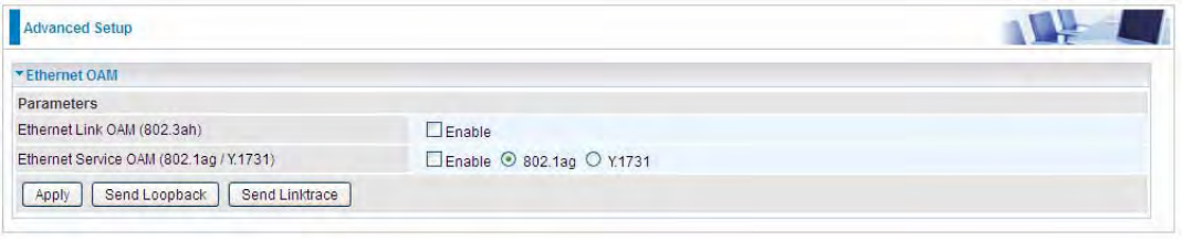
Ethernet Link OAM(802.3ah): Enable to activate Ethernet in the First Mile (EFM) Link OAM to do
link fault management.
Ethernet Service OAM (802.1ag/Y1.1731): Enable to activate Ethernet Service OAM check
mechanism, including connectivity fault management and performance monitoring..
Linktrace: Operators trigger linktrace protocol to perform path discovery and fault isolation in their
networks.Link Trace messages otherwise known as Mac Trace Route are Multicast frames that a
MEP transmits to track the path (hop-by-hop) to a destination MEP which is similar in concept to
User Datagram Protocol (UDP) Trace Route. Each receiving MEP sends a Trace route Reply directly
to the Originating MEP, and regenerates the Trace Route Message.
Loopback: Loopback protocol is used to verify and isolate connectivity faults. Loop-back messages
otherwise known as Mac ping are Unicast frames that a MEP transmits, they are similar in concept
to an Internet Control Message Protocol (ICMP) Echo (Ping) messages, sending Loop-back to
successive MIPs can determine the location of a fault. Sending a high volume of Loop-back
Messages can test bandwidth, reliability, or jitter of a service, which is similar to flood ping. A MEP
can send a Loop-back to any MEP or MIP in the service. Unlike CCMs, Loop back messages are
administratively initiated and stopped.
283
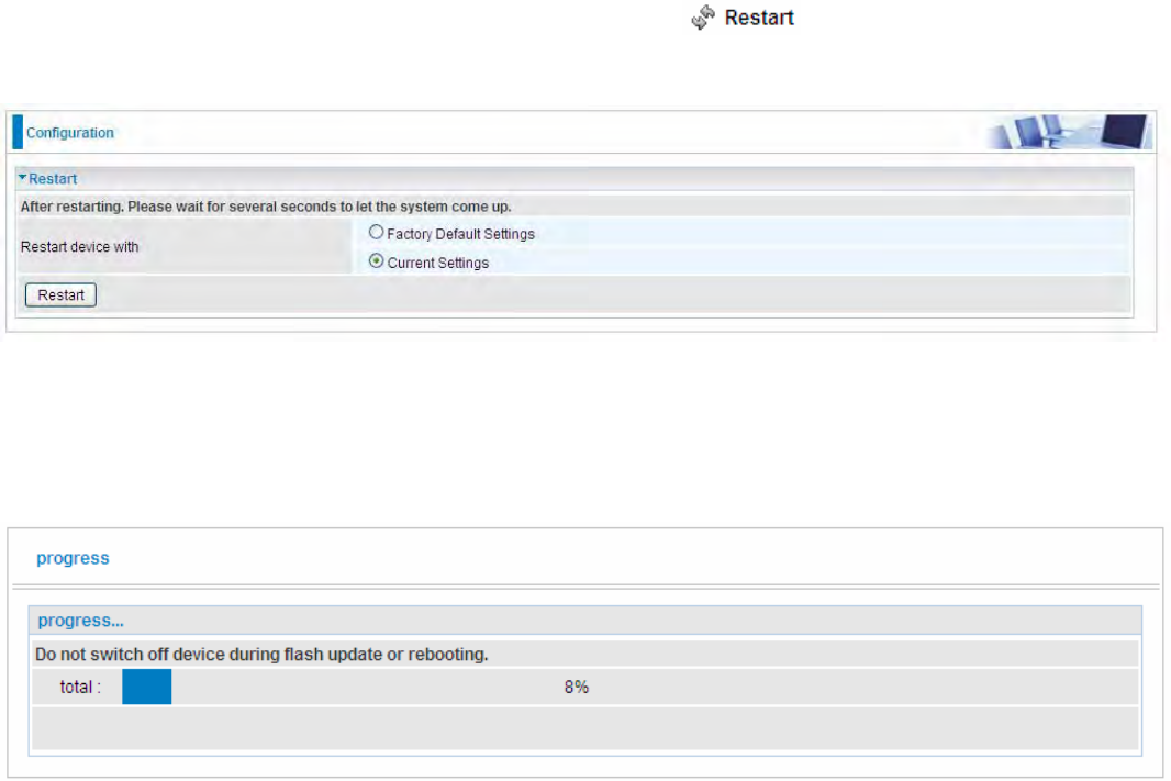
Restart
This section lets you restart your router if necessary. Click in the low right corner of each
configuration page.
If you wish to restart the router using the factory default settings (for example, after a firmware
upgrade or if you have saved an incorrect configuration), select Factory Default Settings to reset to
factory default settings. Or you just want to restart after the current setting, the select the Current
Settings, and Click Restart.

284
Chapter 5: Troubleshooting
If your router is not functioning properly, please refer to the suggested solutions provided in this
chapter. If your problems persist or the suggested solutions do not meet your needs, please kindly
contact your service provider or Billion for support.
Problems with the router
Problem Suggested Action
None of the LEDs is on when you turn
on the router Check the connection between the router and the
adapter. If the problem persists, most likely it is due
to the malfunction of your hardware. Please contact
your service provider or Billion for technical support.
Y
ou have forgotten your login username
or password Try the default username "admin" and password
"admin". If this fails, you can restore your router to
its factory settings by pressing the reset button on
the device rear side.
Problems with WAN interface
Problem Suggested Action
Frequent loss of ADSL line sync
(disconnections) Ensure that all other devices connected to the same
telephone line as your router (e.g. telephones, fax
machines, analogue modems) have a line filter
connected between them and the wall socket (unless
you are using a Central Splitter or Central Filter
installed by a qualified and licensed electrician), and
ensure that all line filters are correctly installed and the
right way around. Missing line filters or line filters
installed the wrong way around can cause problems
with your ADSL connection, including causing frequent
disconnections. If you have a back-to-base alarm
system you should contact your security provider for a
technician to make any necessary changes.

285
Problem with LAN interface
Problem Suggested Action
Cannot PING any PC on LAN Check the Ethernet LEDs on the front panel.
The LED should be on for the port that has a PC
connected. If it does not lit, check to see if the cable
between your router and the PC is properly
connected. Make sure you have first uninstalled your
firewall program before troubleshooting.
Verify that the IP address and the subnet mask are
consistent for both the router and the workstations.

286
Appendix: Product Support & Contact
If you come across any problems please contact the dealer from where you purchased your
product.
Contact Billion
Worldwide:
http://www.billion.com
MAC OS is a registered Trademark of Apple Computer, Inc.
Windows XP, Windows Vista, Windows 7, Windows 8 and Windows 10 are registered Trademarks of
Microsoft Corporation.
287
Federal Communication Commission Interference Statement
This equipment has been tested and found to comply with the limits for a Class B digital device,
pursuant to Part 15 of the FCC Rules. These limits are designed to provide reasonable protection
against harmful interference in a residential installation. This equipment generates, uses, and can
radiate radio frequency energy and, if not installed and used in accordance with the instructions,
may cause harmful interference to radio communications. However, there is no guarantee that
interference will not occur in a particular installation. If this equipment does cause harmful
interference to radio or television reception, which can be determined by turning the equipment off
and on, the user is encouraged to try to correct the interference by one or more of the following
measures:
Reorient or relocate the receiving antenna.
Increase the separation between the equipment and receiver.
Connect the equipment into an outlet on a circuit different from that to which the receiver is
connected.
Consult the dealer or an experienced radio/TV technician for help.
FCC Caution:
This device complies with Part 15 of the FCC Rules. Operation is subject to the following two
conditions:
(1) This device may not cause harmful interference
(2) This device must accept any interference received, including interference that may cause
undesired operation.
Any changes or modifications not expressly approved by the party responsible for compliance could
void the user's authority to operate this equipment. . This device and its antenna(s) must not be co-
located or operating in conjunction with any other antenna or transmitter.
Co-location statement
This device and its antenna(s) must not be co-located or operating in conjunction with any other
antenna or transmitter.
FCC Radiation Exposure Statement
This equipment complies with FCC radiation exposure limits set forth for an uncontrolled
environment. This equipment should be installed and operated with minimum distance 20cm
between the radiator & your body.
7KLVHTXLSPHQWFRPSOLHVZLWK$&7$7,$(,$,6%DQG3DUWRIWKH)&&
UXOHVDQGWKHUHTXLUHPHQWVDGRSWHGE\WKH$&7$2QWKHEDVHRIWKLVHTXLSPHQW
LVDODEHOWKDWFRQWDLQVDPRQJRWKHULQIRUPDWLRQDSURGXFWLGHQWLILHULQWKHIRUPDW
86%'/$%(&$;/,IUHTXHVWHGWKLVQXPEHUPXVWEHSURYLGHGWRWKHWHOHSKRQH
FRPSDQ\
7KLVHTXLSPHQWXVHVWKHIROORZLQJ862&MDFNV5-&
$SOXJDQGMDFNXVHGWRFRQQHFWWKLVHTXLSPHQWWRWKHSUHPLVHVZLULQJDQG
WHOHSKRQHQHWZRUNPXVWFRPSO\ZLWKWKHDSSOLFDEOH)&&3DUWUXOHVDQG
UHTXLUHPHQWVDGRSWHGE\WKH$&7$$FRPSOLDQWWHOHSKRQHFRUGDQGPRGXODU
SOXJLVSURYLGHGZLWKWKLVSURGXFW,WLVGHVLJQHGWREHFRQQHFWHGWRDFRPSDWLEOH
PRGXODUMDFNWKDWLVDOVRFRPSOLDQW6HHLQVWDOODWLRQLQVWUXFWLRQVIRUGHWDLOV
7KH5(1LVXVHGWRGHWHUPLQHWKHQXPEHURIGHYLFHVWKDWPD\EHFRQQHFWHGWRD
WHOHSKRQHOLQH([FHVVLYH5(1VRQDWHOHSKRQHOLQHPD\UHVXOWLQWKHGHYLFHVQRW
ULQJLQJLQUHVSRQVHWRDQLQFRPLQJFDOO,QPRVWEXWQRWDOODUHDVWKHVXPRI5(1V
VKRXOGQRWH[FHHGILYH7REHFHUWDLQRIWKHQXPEHURIGHYLFHVWKDWPD\EH
FRQQHFWHGWRDOLQHDVGHWHUPLQHGE\WKHWRWDO5(1FRQWDFWWKHORFDOWHOHSKRQH
FRPSDQ\7KH5(1IRUWKLVSURGXFWLVVHSDUDWHO\VKRZQRQWKHODEHODQGDOVR
SDUWRIWKHSURGXFWLGHQWLILHUWKDWKDVWKHIRUPDW86%'/$%(&$;/7KHGLJLWV
UHSUHVHQWHGE\DUHWKH5(1ZLWKRXWDGHFLPDOSRLQWHJLVD5(1RI
,IWKLVHTXLSPHQWFDXVHVKDUPWRWKHWHOHSKRQHQHWZRUNWKHWHOHSKRQHFRPSDQ\ZLOO
QRWLI\\RXLQDGYDQFHWKDWWHPSRUDU\GLVFRQWLQXDQFHRIVHUYLFHPD\EHUHTXLUHGXQWLO
WKHSUREOHPLVUHVROYHG%XWLIDGYDQFHQRWLFHLVQRWSUDFWLFDO\RXZLOOEHQRWLILHG
E\WKHWHOHSKRQHFRPSDQ\DVVRRQDVSRVVLEOH<RXZLOOEHDGYLVHGRI\RXUULJKWWR
ILOHDFRPSODLQWZLWKWKH)&&LI\RXEHOLHYHLWLVQHFHVVDU\7KHWHOHSKRQHFRPSDQ\
PD\PDNHFKDQJHVLQLWVIDFLOLWLHVHTXLSPHQWRSHUDWLRQVRUSURFHGXUHVWKDWFRXOG
DIIHFWWKHRSHUDWLRQRIWKHHTXLSPHQW,IWKLVKDSSHQVWKHWHOHSKRQHFRPSDQ\ZLOO
SURYLGHDGYDQFHQRWLFHLQRUGHUIRU\RXWRPDNHQHFHVVDU\PRGLILFDWLRQVWRPDLQWDLQ
XQLQWHUUXSWHGVHUYLFH
7KHWHOHSKRQHFRPSDQ\PD\DVNWKDW\RXGLVFRQQHFWWKLVHTXLSPHQWIURP
WKHQHWZRUNXQWLOWKHSUREOHPKDVEHHQFRUUHFWHGRUXQWLO\RXDUHVXUHWKDWWKH
HTXLSPHQWLVQRWPDOIXQFWLRQLQJ
,I\RXH[SHULHQFHWURXEOHZLWKWKLVHTXLSPHQWRUUHSDLURUZDUUDQW\LQIRUPDWLRQ
SOHDVHFRQWDFWWKHIROORZLQJDGGUHVVDQGSKRQHQXPEHUIRULQIRUPDWLRQ
%LOOLRQ(OHFWULF&R/WG
)1R6HF=KRQJ[LQJ5G;LQGLDQ'LVW1HZ7DLSHL&LW\7DLZDQ
H[