Binsfeld Engineering TX10K TorqueTrak 10K-S Torque Telemetry System User Manual
Binsfeld Engineering Inc TorqueTrak 10K-S Torque Telemetry System Users Manual
UserManual.wiki
>
Binsfeld Engineering
>
TX10K User Manual
Users Manual
Navigation menu
Upload a User Manual
Namespaces
Wiki Guide
HTML
PDF
Info
Views
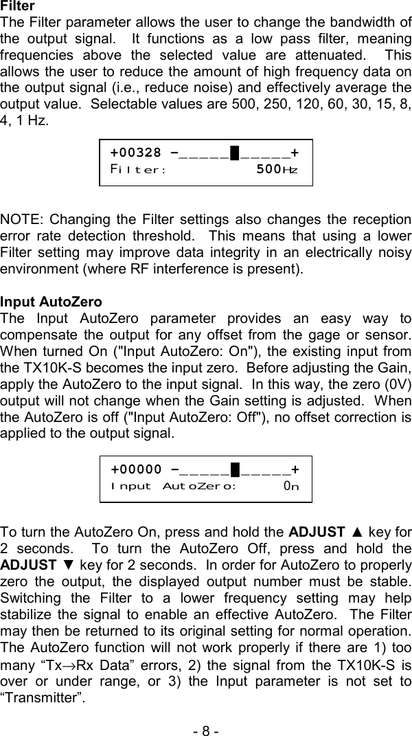
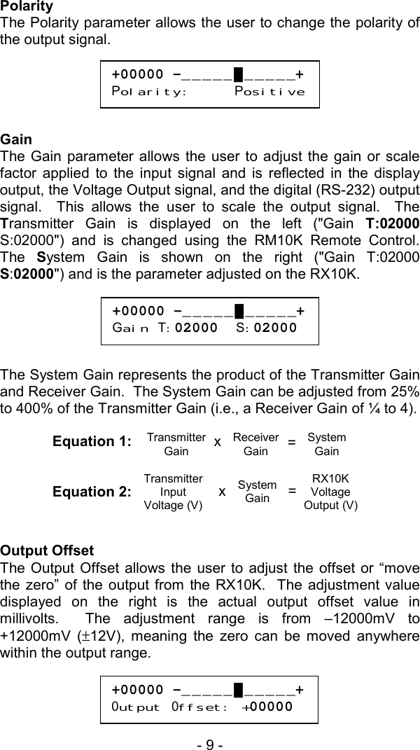
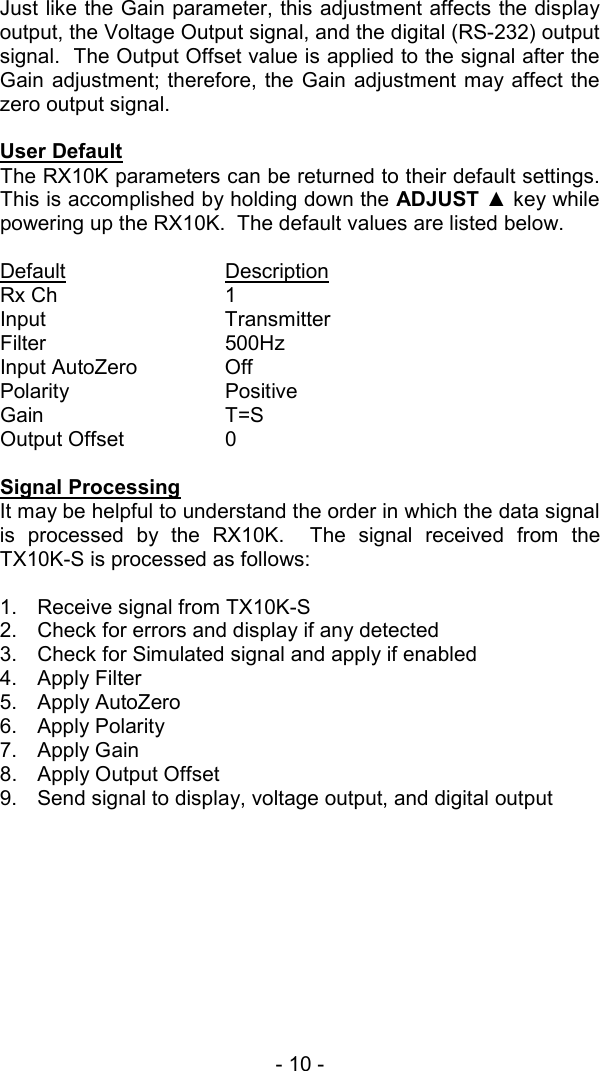
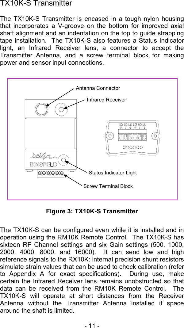
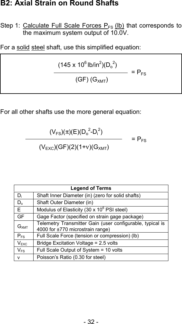
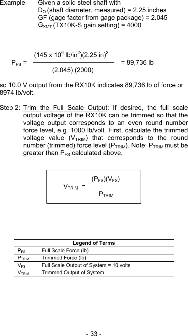
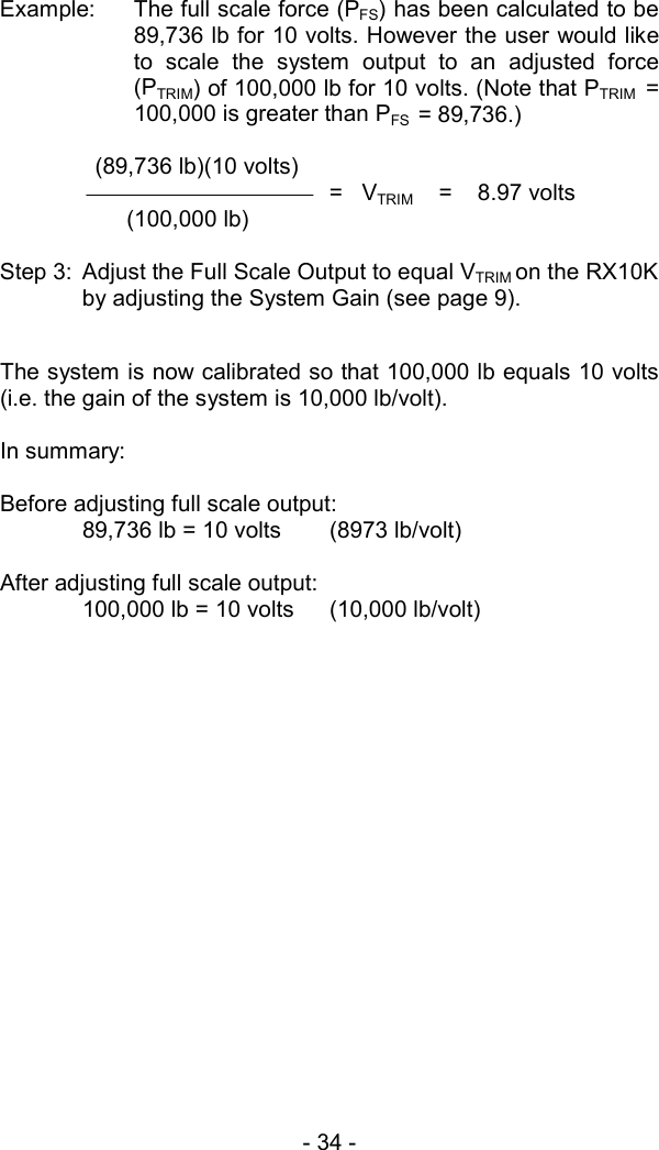
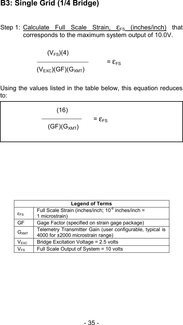
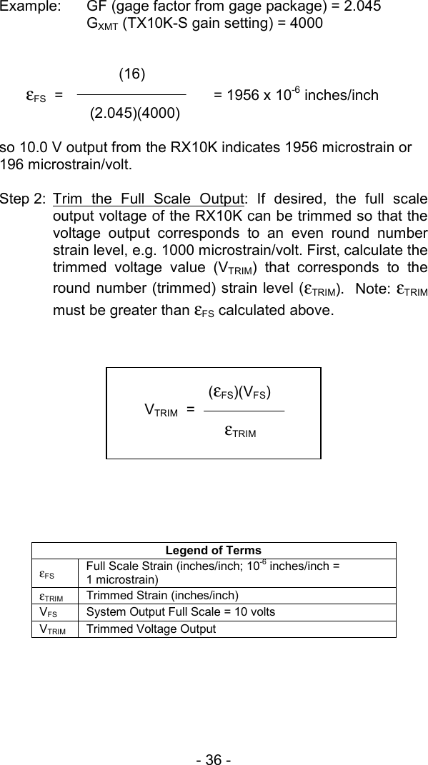
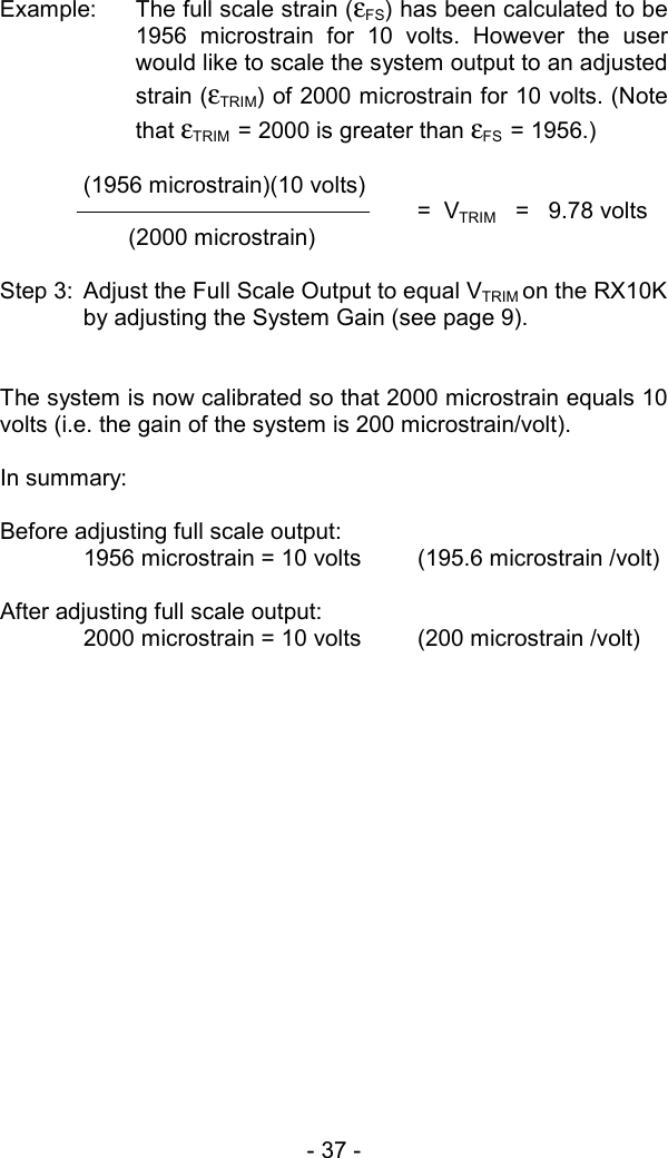
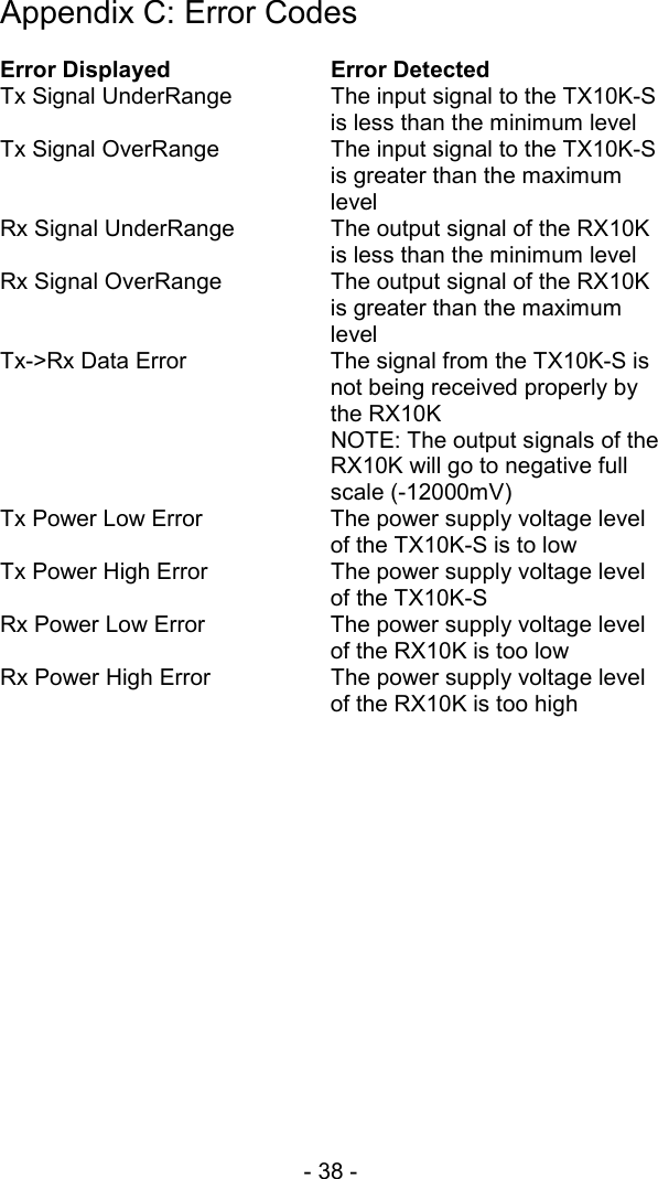
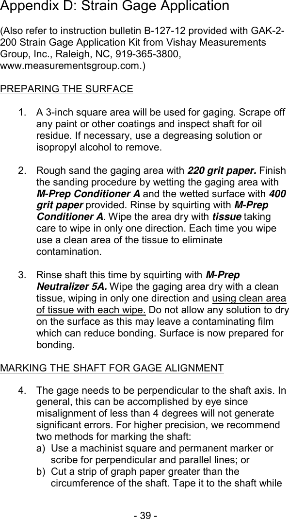
User Manual
Discussion / Help
Navigation